EP4055838B1 - Procédé de fonctionnement d'un système auditif et système auditif - Google Patents
Procédé de fonctionnement d'un système auditif et système auditif Download PDFInfo
- Publication number
- EP4055838B1 EP4055838B1 EP19801504.2A EP19801504A EP4055838B1 EP 4055838 B1 EP4055838 B1 EP 4055838B1 EP 19801504 A EP19801504 A EP 19801504A EP 4055838 B1 EP4055838 B1 EP 4055838B1
- Authority
- EP
- European Patent Office
- Prior art keywords
- dynamic range
- signal
- time
- scheme
- speech
- Prior art date
- Legal status (The legal status is an assumption and is not a legal conclusion. Google has not performed a legal analysis and makes no representation as to the accuracy of the status listed.)
- Active
Links
Images

Classifications
-
- H—ELECTRICITY
- H04—ELECTRIC COMMUNICATION TECHNIQUE
- H04R—LOUDSPEAKERS, MICROPHONES, GRAMOPHONE PICK-UPS OR LIKE ACOUSTIC ELECTROMECHANICAL TRANSDUCERS; ELECTRIC HEARING AIDS; PUBLIC ADDRESS SYSTEMS
- H04R25/00—Electric hearing aids
- H04R25/35—Electric hearing aids using translation techniques
- H04R25/356—Amplitude, e.g. amplitude shift or compression
-
- H—ELECTRICITY
- H03—ELECTRONIC CIRCUITRY
- H03G—CONTROL OF AMPLIFICATION
- H03G3/00—Gain control in amplifiers or frequency changers
- H03G3/20—Automatic control
- H03G3/30—Automatic control in amplifiers having semiconductor devices
- H03G3/32—Automatic control in amplifiers having semiconductor devices the control being dependent upon ambient noise level or sound level
-
- H—ELECTRICITY
- H03—ELECTRONIC CIRCUITRY
- H03G—CONTROL OF AMPLIFICATION
- H03G7/00—Volume compression or expansion in amplifiers
- H03G7/002—Volume compression or expansion in amplifiers in untuned or low-frequency amplifiers, e.g. audio amplifiers
-
- H—ELECTRICITY
- H03—ELECTRONIC CIRCUITRY
- H03G—CONTROL OF AMPLIFICATION
- H03G7/00—Volume compression or expansion in amplifiers
- H03G7/007—Volume compression or expansion in amplifiers of digital or coded signals
-
- H—ELECTRICITY
- H03—ELECTRONIC CIRCUITRY
- H03G—CONTROL OF AMPLIFICATION
- H03G9/00—Combinations of two or more types of control, e.g. gain control and tone control
- H03G9/005—Combinations of two or more types of control, e.g. gain control and tone control of digital or coded signals
-
- H—ELECTRICITY
- H03—ELECTRONIC CIRCUITRY
- H03G—CONTROL OF AMPLIFICATION
- H03G9/00—Combinations of two or more types of control, e.g. gain control and tone control
- H03G9/02—Combinations of two or more types of control, e.g. gain control and tone control in untuned amplifiers
- H03G9/12—Combinations of two or more types of control, e.g. gain control and tone control in untuned amplifiers having semiconductor devices
- H03G9/18—Combinations of two or more types of control, e.g. gain control and tone control in untuned amplifiers having semiconductor devices for tone control and volume expansion or compression
-
- H—ELECTRICITY
- H04—ELECTRIC COMMUNICATION TECHNIQUE
- H04R—LOUDSPEAKERS, MICROPHONES, GRAMOPHONE PICK-UPS OR LIKE ACOUSTIC ELECTROMECHANICAL TRANSDUCERS; ELECTRIC HEARING AIDS; PUBLIC ADDRESS SYSTEMS
- H04R2225/00—Details of deaf aids covered by H04R25/00, not provided for in any of its subgroups
- H04R2225/41—Detection or adaptation of hearing aid parameters or programs to listening situation, e.g. pub, forest
Definitions
- the invention relates to a method for operating a hearing system and a corresponding hearing system.
- a hearing system has a signal processor and a receiver, whereby the receiver is also referred to as a loudspeaker.
- An input signal is fed to the signal processor, which is then modified by the signal processor so that an output signal is generated, which is therefore a modified input signal.
- the input signal is amplified with a certain gain factor.
- the input signal and the output signal are generally also referred to as signals.
- the output signal is finally output via the receiver.
- the input signal and the output signal are electrical signals.
- the receiver then converts the output signal into a sound signal.
- the hearing system also has a microphone, which generates the input signal by recording one or more sound signals from the environment and converting them into the input signal.
- a hearing system with an additional microphone is also called a hearing aid and is used, for example, to provide support to a hearing-impaired person by using the hearing aid to amplify sound signals from the environment and output them to the person as amplified sound signals.
- non-linear amplification In hearing systems, it is possible to use non-linear amplification instead of a simple linear amplification. This is achieved, for example, with a so-called compressor, which provides and applies a compression scheme that, when modifying the input signal, i.e. when Generation of the output signal sets the gain factor appropriately.
- the behavior of the compressor, ie the compression scheme is defined by one or more parameters, more precisely compression parameters.
- the method is used to operate a hearing system and is therefore an operating method.
- the hearing system is worn by a user, in particular on, in or behind the ear, i.e. generally on the head and in the area of one or more both ears.
- the hearing system and the user are in a current acoustic environment. This means that the environment around the user and the hearing system forms a certain acoustic backdrop at the current time.
- the hearing system has a signal processing unit which generates an output signal from the hearing system from an input signal of the hearing system by amplifying the input signal with an amplification factor.
- the signal processing unit therefore acts as an amplifier.
- the signal processing unit is preferably integrated into the hearing system.
- the hearing system is preferably a hearing aid, particularly preferably a hearing aid for the care of a hearing-impaired person.
- the hearing system has at least one microphone which picks up acoustic signals, i.e. sound signals from the environment, and converts them into an input signal.
- the hearing system also has a receiver, via which the output signal, i.e. the amplified input signal, is output.
- the receiver is also referred to as a loudspeaker.
- the amplification factor is set by an automatic gain control, which is a part of the signal processing.
- the automatic gain control is also referred to as AGC (automatic gain control). "Automatic" means in particular that no user input is required to carry out the gain control; this happens automatically during operation.
- AGC automatic gain control
- Automatic means in particular that no user input is required to carry out the gain control; this happens automatically during operation.
- the hearing system in a suitable design also has a manual gain control, which the user can use to further influence the gain factor as desired.
- the automatic gain control has a dynamic processor that can be operated with a dynamic scheme that defines the gain factor as a function of a level of the input signal, i.e. the input level.
- the dynamic scheme therefore specifies which gain factor is used at which input level.
- the dynamic scheme is also referred to as a dynamic algorithm. Examples of dynamic schemes are generally compression or expansion schemes and especially AGCi (automatic gain control input dependent) and ADRO (adaptive dynamic range optimization). Various dynamic schemes are suitable in this case, AGCi is particularly preferred.
- a characteristic of a dynamic processor is that the amplification factor is not constant, but that the dynamic processor leads to a non-linear amplification.
- the dynamic processor regulates the amplification in particular through signal processing depending on a controlled variable.
- the input level is used as a controlled variable, for example, or alternatively the output level. Both variants have specific advantages and disadvantages.
- the respective level is measured, for example, using a level detector, which is conveniently part of the hearing system.
- the input signal and the output signal each have a dynamic range, i.e. a level that lies within a certain range that goes from a minimum to a maximum level.
- the level of the input signal is also called the input level, and the level of the output signal is called the output level.
- the dynamic range of the input signal is called the input dynamic range
- the dynamic range of the output signal is called the output dynamic range.
- the dynamic range of the output signal depends on the dynamic range of the input signal and on the modification by the signal processing. In certain applications it is desirable to limit the dynamic range of the output signal, i.e. to compress it, or to increase it, i.e. to expand it.
- the dynamic range is expediently adapted to the hearing-impaired person's reduced hearing compared to someone with normal hearing.
- the reduced hearing is restricted to a certain level range, which then expediently defines the dynamic range of the output signal.
- the dynamics of the input signal are then mapped to the level range by generating the output signal with a suitable dynamic range, in particular to achieve maximum sound quality.
- the hearing system is operated in a specific program to which a dynamic scheme is assigned.
- the program therefore sets the dynamic processor in a predefined manner, i.e. pre-configures it.
- the program and the dynamic scheme are appropriately matched to the current acoustic environment so that an optimal output, i.e. output quality, is achieved.
- the dynamic processor is therefore operated in one program with the associated dynamic scheme during operation.
- a core idea of the invention is that at least one situation parameter is determined which characterizes the current acoustic environment, i.e. in particular quantifies or qualifies it.
- the assigned dynamic scheme is modified depending on the situation parameter, so that the dynamic processor is operated with a modified dynamic scheme.
- the dynamic scheme specified by the program for the current acoustic environment is thus optimized in relation to the situation.
- the dynamic scheme for the automatic gain control is modified depending on the situation. This is based on the idea that the acoustic environment can change and the selected dynamic scheme is therefore no longer optimal, although the change may not be sufficiently strong or long-lasting to justify a change of program, e.g. from a speech to a music program.
- the dynamics are not adapted solely as a function of the input level or the output level, but rather the situation parameter is preferably additionally fed to the automatic amplification unit and used as an additional control or regulating variable.
- the situation parameter is preferably determined by means of a detector.
- the detector is preferably part of the hearing system.
- the situation parameter is determined externally with respect to the hearing system and transmitted to the hearing system, e.g. via a data connection.
- a compressor and an expander typically work in opposite directions. While a compressor usually limits the gain factor above a threshold value, an expander usually increases the gain factor above a threshold value. In other words: a compressor amplifies signals with a low level more than signals with a high level, and an expander, conversely, amplifies signals with a high level more than signals with a low level. Overall, a compressor reduces the dynamics of a signal and a compressor increases the dynamics of a signal.
- Another advantageous embodiment is one in which a compressor and an expander are combined, either as two separate dynamic processors or together as a single dynamic processor.
- the compressor and the expander are used independently of one another, so that only one of them is active at a time, e.g. depending on the situation parameter or a program set in the hearing system.
- the compressor and the expander are active simultaneously in a so-called hybrid mode, preferably in such a way that the compressor lowers the level overall and the expander increases the dynamics again at one operating point, ie in a limited frequency and/or level range.
- the expander is used to locally counteract what is essentially global compression.
- a reverse embodiment, in which the expander acts globally and the compressor only locally, is also fundamentally possible and suitable.
- the modification within a given program is ultimately a special adaptation of the program itself to individual deviations of the current acoustic environment from an idealized environment or standard environment predicted when the program was created.
- One problem when operating a hearing system is that different situations exist simultaneously in different environments, which require mutually exclusive programs.
- a particularly important case is the presence of speech in the environment.
- a program is expediently set that improves speech intelligibility.
- the realistic reproduction of other sound signals or noises is of secondary importance; the priority is to make speech recognizable for the user.
- a special dynamic scheme designed for maximum speech intelligibility is set and used.
- the aim is expediently to achieve a reproduction of the acoustic environment that is as close to reality as possible.
- the aim is to achieve the best possible sound quality.
- the best possible sound quality is understood in particular to mean that the user's hearing loss is compensated for as optimally as possible, i.e. maximum hearing loss compensation is carried out.
- This is particularly important for music, which may be heavily distorted by a dynamic scheme to improve speech intelligibility.
- the same applies to other sound signals in the environment which are sometimes so heavily distorted that they are no longer recognizable to the user and can no longer be assigned. This leads to particular problems when both speech and other sound signals are present in the environment, i.e.
- the acoustic environment generally includes several different sound signals to which different programs are assigned for optimal output, e.g. a speech program on the one hand and a music program on the other.
- a compromise is possible here by using a program that is not just optimized in one direction, but rather attempts to reproduce all sound signals at least partially appropriately.
- none of the sound sources are output optimally, so that with such a program, speech in particular can never be optimally understood.
- the dynamic scheme is modified depending on the situation by determining at least one situation parameter and, if appropriate, several situation parameters, particularly on a recurring basis, in order to ensure optimal adjustment of the dynamic processor at the appropriate time.
- the dynamic processor is adapted to the situation.
- the situation parameter is determined by the hearing system itself.
- the situation parameter indicates whether speech is present in the environment or not and the dynamic scheme is modified in favor of speech intelligibility if speech is present, and otherwise in favor of sound quality.
- a program is set which is optimized for maximum sound quality, advantageously a music program.
- speech intelligibility is then prioritized and the program, especially the dynamic scheme, is modified in such a way that maximum speech intelligibility is achieved, in particular without changing the actual program.
- the modification is expediently only maintained as long as speech is present.
- the modification is carried out automatically, advantageously no user input is required.
- the user also does not need to select a special speech program or sound or music program. It therefore reacts directly to the current acoustic environment, a detour via a program selection is not necessary.
- the program is therefore not static, but dynamic depending on the situation parameter due to the modification carried out. This ensures that the user generally experiences maximum sound quality, but maximum speech intelligibility in situations with speech.
- the detector is expediently a speech detector, which in particular examines the input signal for the presence of speech.
- the dynamic scheme defines the behavior of the dynamic processor during operation and is defined by one or more parameters, more precisely dynamic parameters, e.g. compression parameters and/or expansion parameters.
- Suitable dynamic parameters are in particular a compression or expansion threshold, also known as the knee point, a compression or expansion ratio, also known as compression or expansion for short, a switch-on time, also known as attack, and a switch-off time, also known as release.
- the switch-on time and the switch-off time of the dynamic processor are also each referred to as a time constant.
- the dynamic scheme is modified by changing the switch-on time and/or the switch-off time.
- the dynamic scheme is modified by changing at least one further parameter of the dynamic scheme, wherein the parameter is selected from a set of parameters comprising: a knee point, a compression ratio in the case of a compressor, an expansion ratio in the case of an expander.
- the switch-on time or the switch-off time or both are changed depending on the situation.
- the other parameters are also suitable for modifying the dynamic scheme.
- the program does not switch between two different dynamic schemes, but basically uses the same dynamic scheme, ie the same dynamic algorithm, whose parameters are, however, adapted depending on the situation, so that the basic concept underlying the dynamic scheme is retained and only modified in its concrete implementation.
- the parameterization of the dynamic scheme is changed dynamically.
- Dynamic schemes for maximizing sound quality and speech intelligibility are generally known. For example, for maximum sound quality, the aim is to achieve amplification that is as linear as possible, so that the dynamic scheme only carries out compression for high input levels, whereas no compression takes place for low and medium input levels and the compression ratio is in particular 1. A knee point that marks the transition to a higher compression ratio is then arranged comparatively high, i.e. in comparison to a knee point of a dynamic scheme for maximum speech intelligibility.
- the level range of the input signal that contains speech is mapped as far as possible to the level range that the user can hear.
- the situation parameter is a signal-to-noise ratio of the current acoustic environment and in particular of the input signal, so that the dynamic scheme is modified depending on the signal-to-noise ratio of the current acoustic environment.
- the dynamic scheme is therefore set depending on the relative strength of noise compared to a useful signal, i.e. a sound signal that the user wants to perceive, in the environment. This is based on the idea that that with a high signal-to-noise ratio, the useful signal is already sufficiently understandable for the user and only a small amount of adjustment, especially compression, is necessary for the benefit of the sound quality and is carried out accordingly.
- a noise detector is expediently used as a detector for the signal-to-noise ratio, to which the input signal in particular is fed, on the basis of which the signal-to-noise ratio of the environment is then determined.
- the signal-to-noise ratio is a ratio of a signal that comes from a speaker and a noise that comes from one or more other sound sources in the environment.
- the other sound sources are, for example, other people, e.g. an audience, or devices, e.g. a vehicle in which the user and the speaker are located.
- the dynamic scheme has two time constants, namely a switch-on time and a switch-off time. In the case of a negative signal-to-noise ratio, at least one of the time constants is reduced and, conversely, in the case of a positive signal-to-noise ratio, at least one of the time constants is increased.
- a time constant is reduced is understood to mean that a fast time constant is set.
- a time constant is increased is understood to mean that a slow time constant is set.
- fast is understood to mean a time of up to 10 ms and “slow” a time of 100 ms to 1 s.
- switch-off time “fast” is generally understood to mean a time of up to 100 ms and “slow” a time of 500 ms to 1 s.
- both time constants are reduced and conversely, in the case of a positive signal-to-noise ratio, both time constants are increased.
- the user benefits in particular from gaps in the input signal, i.e. from short periods of time in which the noise is very low, where short is understood to mean a length of no more than one second.
- gaps are expediently amplified by modifying the dynamic scheme according to the situation with correspondingly fast time constants.
- fast is understood to mean a time constant of no more than 100ms.
- a further situation parameter is an environment class, so that the dynamic scheme is modified depending on the environment class, the environment class being selected in particular from a set of classes, comprising: speech, music, noise.
- the situation parameter is determined in particular by means of a detector which is designed as a classifier.
- the classifier is expediently part of the signal processing and determines the environment class in particular based on the input signal. If the environment class is music, the dynamic scheme is modified more conservatively, ie it is compressed less than, for example, with speech. In the case of speech, the dynamic scheme is then modified for maximum speech intelligibility. This is advantageously used at a concert or similar environments in which there is no speech.
- the dynamic scheme is then modified with a view to reproducing music, rhythms and melodies as realistically as possible, so the aim is in particular to achieve as linear an amplification as possible for the user.
- a further situation parameter is a movement pattern, so that the dynamic scheme is modified depending on a movement of the hearing system, wherein the movement pattern is in particular selected from a set of movement patterns, comprising: a resting position, a walking movement, a running movement, a journey.
- the movement pattern is in particular determined by means of a detector which is designed as a movement sensor, preferably by means of an acceleration sensor.
- a distinction is made in particular between movement and rest.
- the movement is expediently further divided into different types of movement, e.g. according to speed. For example, it is recognized whether the user is standing still, walking or driving in a car. This is based on the idea that in general, speech intelligibility is of varying importance in different environmental situations and therefore the dynamic scheme is expediently modified depending on the user's state of movement or behavior.
- a further situation parameter is a stationarity of the current acoustic environment and in particular of the input signal, so that the dynamic scheme is modified depending on the stationarity of the current acoustic environment.
- a stationarity detector is expediently used, to which in particular the input signal is fed, on the basis of which the stationarity is then determined.
- the stationarity is in particular a measure of the dynamics of one or more sound sources in the environment, i.e. a measure of the temporal change in the level of this sound source or sources. The stationarity therefore indicates the dynamics of the time-dependent level.
- a further situation parameter is a diffuseness of the current acoustic environment, so that the dynamic scheme is modified depending on the diffuseness of the current acoustic environment.
- a diffuseness detector is expediently used, to which in particular the input signal is fed, on the basis of which the diffuseness is then determined.
- the diffuseness is similar to the stationarity described above in that the diffuseness is a measure of a variation of the level in the environment, but not time-dependent, but location-dependent.
- the diffuseness indicates how directional the environment is, i.e. whether sound signals come to the user from a certain direction, i.e. directed, or evenly from all directions, i.e. diffuse.
- the diffuseness indicates the dynamics of the direction-dependent level. A spatially very homogeneous level therefore leads to a high degree of diffuseness.
- a further situation parameter is a distance of the hearing system, in particular of a microphone if present, to a sound source, in particular to a speaker, in the current acoustic environment, so that the dynamic scheme is modified depending on the distance.
- the distance is determined in particular using a rangefinder as a detector. Since the hearing system is worn by the user, the distance between the hearing system and the sound source also corresponds to the distance between the user and the sound source. This is based on the consideration that sound sources further away are usually less understandable and therefore the dynamic scheme is expediently modified in this case for greater speech intelligibility.
- a further situation parameter is a reverberation time of the current acoustic environment, so that the dynamic scheme is modified depending on the reverberation time, wherein the dynamic scheme has two time constants, namely a switch-on time and a switch-off time, wherein the reverberation time is determined repeatedly and in the event of an increase in the reverberation time at least one of the time constants is increased and vice versa in the event of a reduction in the reverberation time is reduced.
- the reverberation time is expediently determined by means of a detector to which the input signal is fed, so that the detector determines the reverberation time based on an analysis of the input signal.
- a combination of the different concepts described above is also particularly advantageous.
- several situation parameters are then determined and used to control the automatic gain control.
- the same situation parameter is determined redundantly using several similar or different detectors.
- one program is a universal program.
- the universal program is characterized in particular by the fact that it is not adapted to a specific, predefined situation or used in a specific, limited area of application, but is used in several different situations.
- the hearing system is operated exclusively using one program, so that a design with different programs, each of which is specifically adapted and optimized for different environments is dispensed with. Instead, adaptation to a changed acoustic environment takes place solely by means of the dynamic scheme that is modified depending on the situation.
- the hearing aid has one or more special programs in addition to the universal program, each of which is adapted for specific, concrete situations.
- a respective special program can be set by the user and is preferably not set automatically.
- the special programs are unchangeable, i.e. they specify fixed and predetermined parameter values for a specific situation, specifically for the dynamic scheme but also generally, the universal program is variable, at least due to the situation-adapted dynamic scheme.
- the universal program is therefore generally referred to as an automatic program, as it automatically adapts to the environment, whereas the individual special programs are static.
- the situation parameter is fed directly to the automatic gain control and used to control the gain factor.
- the option of manual gain adjustment is also dispensed with.
- Manual adjustment by the user is only possible by selecting a special program. All adjustments are carried out automatically and situation-dependently starting from the universal program by modifying the dynamic scheme depending on the situation parameter.
- the dynamic scheme is modified depending on the frequency.
- the input signal has a frequency spectrum which is now divided into at least two frequency ranges.
- a frequency range is in particular a single frequency or a frequency interval.
- the input signal is expediently divided into several consecutive frequency ranges using a filter bank of the signal processing.
- the frequency ranges preferably do not overlap, apart from a possible minor overlap in the edge area for technical reasons.
- the dynamic scheme is now not only modified in the same way for the entire frequency spectrum, but specifically for the individual frequency ranges. The previously described method in which the dynamic scheme is modified is thus carried out in parallel in several frequency ranges, so to speak.
- the dynamic scheme is specifically modified for certain frequency ranges, so that optimal adaptation to the current acoustic environment is guaranteed.
- the frequency-dependent modification of the dynamic scheme is suitable for all situation parameters described. In principle, a design in which compression or expansion is carried out in different frequency ranges as required, or both in combination, is also suitable.
- the dynamic scheme is modified according to the invention by the switch-on time of the dynamic scheme or the switch-off time of the dynamic scheme or both are changed depending on the frequency.
- the switch-on time or the switch-off time or both parameters are changed independently of each other for different frequency ranges, so that different time constants may also result for different frequency ranges. This means that certain frequency ranges are specifically modified in terms of the time constant without making the same modification for all other frequency ranges.
- speech frequency ranges and speech-free frequency ranges, i.e. between frequency ranges that contain speech and frequency ranges that do not contain speech.
- a suitable speech frequency range is a frequency range from 800 Hz to 4 kHz or a subset thereof. Suitable speech-free frequency ranges are accordingly frequency ranges below 800 Hz and above 4 kHz.
- a more detailed division of the frequency spectrum is carried out in which the speech frequency ranges correspond to individual sounds or formants and all other frequencies then form speech-free frequency ranges.
- a parameter of the dynamic scheme is changed depending on the frequency by setting the parameter on a respective frequency range depending on whether this frequency range is a speech frequency range or a speech-free frequency range.
- the frequency-dependent modification therefore corresponds to a speech-dependent modification. Overall, this advantageously discriminates between the speech-free frequency ranges and the dynamic scheme is optimally modified for both types of frequency range. This results in improved speech intelligibility in particular.
- the language-dependent modification of the dynamic scheme is also suitable for all described situation parameters.
- a combination of the speech-dependent modification with the already mentioned embodiment is carried out, in which the situation parameter is a signal-to-noise ratio of the current acoustic environment and in particular of the input signal.
- the situation parameter is a signal-to-noise ratio of the current acoustic environment and in particular of the input signal.
- a speech frequency range at least one of the time constants of the dynamic scheme is reduced as already described and, conversely, in the case of a positive signal-to-noise ratio, the at least one time constant is increased.
- the at least one time constant is increased and, in the case of a positive signal-to-noise ratio, the at least one time constant is reduced.
- the time constant is preferably the switch-off time.
- a time constant is reduced is preferably understood to mean that a fast time constant is set.
- a time constant is increased is accordingly preferably understood to mean that a slow time constant is set.
- a design is also possible in which another parameter of the dynamic scheme is modified in a frequency-dependent manner, e.g. a compression or expansion ratio or a respective knee point in different frequency ranges are changed independently of one another and thus possibly differently.
- the hearing system according to the invention has a signal processing system which is designed to carry out a method as described above.
- the hearing system also has a receiver for outputting an output signal.
- the hearing system is preferably designed as a hearing aid and has one or more microphones for generating the input signal.
- the hearing aid is, for example, a BTE, ITE or RIC device.
- the hearing aid has a housing in which the microphone is housed.
- the signal processing is preferably also arranged in the housing.
- a battery is expediently arranged in the housing to supply energy to the hearing aid.
- the receiver is either housed in the housing or connected to the housing via a supply line, in particular a cable.
- the hearing aid is either monaural designed, with only a single housing, or binaural, with two housings, each with one or more microphones and each with a
- the housings of the binaural hearing aid are then worn on different sides of the user's head.
- a microphone is not mandatory in the hearing system, so that in a suitable design the hearing system does not have a microphone and is designed, for example, as a headphone.
- Fig. 1 shows a hearing system 2, which in the present case is designed as a hearing aid, more precisely as a RIC device, which is worn behind the ear by a user who is particularly hearing impaired.
- the hearing system 2 in the exemplary embodiment has one or more, and here two, microphones 4 for generating an input signal E from sound signals from the environment.
- the presence of a microphone 4 is not mandatory, however, so that in one variant the hearing system 2 does not have a microphone and is, for example, a headphone.
- the hearing system 2 also has a signal processing unit 6 and a receiver 8 as well as a battery 10 for power supply.
- the hearing system 2 also has a housing 12 in which the microphones 4, the signal processing unit 6 and the battery 10 are arranged.
- the receiver 8 is connected to the housing via a supply line 14 and in Fig. 1 integrated into an earpiece which is inserted into the user's ear.
- the microphones 4 convert the sound signals in the environment into an input signal E, which is fed to the signal processing 6 and modified by it.
- the signal processing 6 generates an output signal A, which is therefore a modified input signal E.
- the input signal E is amplified with a certain amplification factor V.
- the output signal A i.e. the amplified input signal E, is finally output to the user via the earpiece 8.
- the input signal E and the output signal A are both electrical signals.
- the earpiece 8 then converts the output signal A into a sound signal.
- the hearing system 2 is either monaural or binaural.
- a binaural hearing system 2 then has, for example, two housings 12 with the associated components as in Fig. 1 shown, whereby the signal processing 6 does not have to be identical in both cases.
- Fig. 2 the hearing system 2 is shown as a block diagram.
- the signal processing 6 has an amplifier 16, which is fed with the input signal E and which then amplifies it and passes it on to the receiver 8 as an output signal A.
- the amplification in the amplifier 16 takes place with a gain factor V, which is set by an automatic gain control.
- this has a dynamic processor 18.
- the hearing system 2 is now operated in a program to which a certain dynamic scheme is assigned, with which the dynamic processor 18 is operated during operation in the one program.
- the respective dynamic scheme defines the gain factor V as a function of a level of the input signal E.
- the function is characterized by various parameters, in this case e.g. by one or more knee points, one or more compression or expansion ratios, a switch-on time (attack), a switch-off time (release) or a combination thereof.
- the dynamic processor 18 is either a compressor or an expander or a combination thereof. In an embodiment not shown, two dynamic processors 18 are present, one of which is a compressor and the other is an expander, in which case the statements for the embodiment shown apply analogously.
- a situation parameter S is determined which characterizes the current acoustic environment and which is then used during operation in one program to modify the associated dynamic scheme.
- the dynamic processor 18 is then operated with a modified dynamic scheme depending on the situation parameter S.
- a detector 20 is arranged, which here is part of the hearing system 2.
- the detector 20 is generally connected to the signal unit 6 and specifically to the automatic gain control, here specifically to the dynamic processor 18.
- the detector 20 is, for example, a speech detector which determines whether speech is present in the environment. Alternatively, the detector 20 determines a signal-to-noise ratio in the environment as a situation parameter S. For this purpose, in a suitable embodiment, the input signal E is fed to the detector 20 so that it determines the signal-to-noise ratio of the input signal E as a situation parameter S.
- the detector 20 is a classifier which, for example, assigns the environment to a certain environment class based on the input signal E.
- the detector 20 is a motion detector, for example an acceleration sensor, which determines a movement pattern as a situation parameter S.
- the motion detector determines, for example, whether the user is moving or not, or how quickly the user is moving or in which direction, or a combination thereof.
- the detector 20 is a stationarity detector which determines the stationarity of the environment, i.e. how the temporal dynamics of the sound signals in the environment are.
- the detector 20 is fed with the input signal E, for example, whose stationarity, i.e. its temporal change, is then determined by the detector 20 and output as situation parameter S.
- the detector 20 is a diffuseness detector, which determines the diffuseness of the environment, ie the spatial distribution of the sound signals in the environment.
- the detector 20 is fed with the input signal E, for example, whose directionality, i.e.
- detector 20 determines and outputs it as situation parameter S.
- detector 20 is a rangefinder which determines the distance of hearing system 2 to a sound source in the environment and then outputs this distance as situation parameter S.
- detector 20 determines the reverberation time in the environment, e.g. based on an analysis of input signal E. In a variant not shown, several identical or different detectors 20 mentioned above are combined.
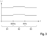
- Fig. 3 an embodiment of a frequency-dependent modification of the dynamic scheme is shown.
- a parameter of the dynamic scheme is changed differently for different frequencies f.
- the input signal E has a frequency spectrum which is divided into three frequency ranges B1 - B3.
- the dynamic scheme is now not only modified in the same way for the entire frequency spectrum, but specifically for the individual frequency ranges B1 - B3.
- the previously described method in which the dynamic scheme is modified is thus carried out in parallel in the frequency ranges B1 - B3, so to speak.
- the switch-off time t_r of the dynamic scheme is changed depending on the frequency.
- speech frequency ranges B2 here from 800 Hz to 4 kHz
- speech-free frequency ranges B1, B3, here below 800 Hz and above 4 kHz are distinctions made between speech frequency ranges B2, here from 800 Hz to 4 kHz
- speech-free frequency ranges B1, B3, here below 800 Hz and above 4 kHz are distinctions made between speech frequency ranges B2, here from 800 Hz to 4 kHz
- speech-free frequency ranges B1, B3, here below 800 Hz and above 4 kHz here below 800 Hz and above 4 kHz.
- a more detailed division of the frequency spectrum is made, in which the speech frequency ranges correspond to individual sounds or formants and all other frequencies then form speech-free frequency ranges.
- the switch-off time t_r and generally a parameter of the dynamic scheme is changed in this case depending on the frequency by setting it to a respective frequency range B1 - B3 depending on whether this frequency range B1 - B3 is a speech frequency range B2 or a speech-free frequency range B1, B3.
- the frequency-dependent modification therefore corresponds to a speech-dependent modification.
- Fig. 3 This is combined with a design in which the situation parameter S is a signal-to-noise ratio of the current acoustic environment.
- the frequency-dependent switch-off time t_r in case of a positive signal-to-noise ratio is Fig. 3 shown by solid lines and in the case of a negative signal-to-noise ratio by dashed lines.
- the switch-off time t_r is reduced on the speech frequency range B2 and conversely, in the case of a positive signal-to-noise ratio, the switch-off time t_r is increased.
- the switch-off time t_r is increased and in the case of a positive signal-to-noise ratio, the switch-off time t_r is reduced.
- “Reduced” means that a fast switch-off time t_r is set and "increased” means that a slow switch-off time t_r is set. The same procedure is also basically suitable for the switch-on time.
- an embodiment is also suitable in which another parameter of the dynamic scheme is modified in a frequency-dependent manner, e.g. a compression or expansion ratio or a respective knee point are changed independently of one another and thus possibly differently in different frequency ranges.
- another parameter of the dynamic scheme is modified in a frequency-dependent manner, e.g. a compression or expansion ratio or a respective knee point are changed independently of one another and thus possibly differently in different frequency ranges.
Landscapes
- Engineering & Computer Science (AREA)
- Multimedia (AREA)
- Health & Medical Sciences (AREA)
- General Health & Medical Sciences (AREA)
- Neurosurgery (AREA)
- Otolaryngology (AREA)
- Physics & Mathematics (AREA)
- Acoustics & Sound (AREA)
- Signal Processing (AREA)
- Circuit For Audible Band Transducer (AREA)
- Tone Control, Compression And Expansion, Limiting Amplitude (AREA)
- Control Of Amplification And Gain Control (AREA)
Claims (14)
- Procédé de fonctionnement d'un système auditif (2) dans un environnement acoustique actuel,- le système auditif (2) comportant un traitement de signal (6),- le traitement de signal (6) générant un signal de sortie (A) à partir d'un signal d'entrée (E) par amplification du signal d'entrée (E) avec un facteur d'amplification (V),- le système auditif (2) comportant un écouteur (8) qui délivre le signal de sortie (A),- le facteur d'amplification (V) étant réglé par une régulation d'amplification automatique qui comporte un processeur de dynamique (18) qui peut fonctionner avec un schéma de dynamique qui définit le facteur d'amplification (V) en fonction d'un niveau du signal d'entrée (E),- le système auditif (2) fonctionnant dans un programme auquel est associé un schéma de dynamique permettant de faire fonctionner le processeur de dynamique (18) pendant le fonctionnement dans l'un des programmes,- au moins un paramètre de situation (S) étant déterminé qui caractérise l'environnement acoustique actuel,- pendant le fonctionnement dans un programme, le schéma de dynamique associé étant modifié en fonction du paramètre de situation (S), de sorte que le processeur de dynamique (18) fonctionne avec un schéma de dynamique modifié,
caractérisé en ce que- le paramètre de situation (S) est un rapport signal sur bruit de l'environnement acoustique actuel, de sorte que le schéma de dynamique est modifié en fonction du rapport signal sur bruit de l'environnement acoustique actuel,- le rapport signal sur bruit est le rapport d'un signal provenant d'un haut-parleur et d'un bruit provenant d'une ou plusieurs autres sources acoustiques,- le schéma de dynamique comportant deux constantes de temps, à savoir un temps d'activation et un temps de désactivation,- dans le cas d'un rapport signal sur bruit négatif, au moins une des constantes de temps est réduite et, à l'inverse, dans le cas d'un rapport signal sur bruit positif, au moins une des constantes de temps est augmentée. - Procédé de fonctionnement d'un système auditif (2) dans un environnement acoustique actuel,- le système auditif (2) comportant un traitement de signal (6),- le traitement de signal (6) générant un signal de sortie (A) à partir d'un signal d'entrée (E) par amplification du signal d'entrée (E) avec un facteur d'amplification (V),- le système auditif (2) comportant un écouteur (8) qui délivre le signal de sortie (A),- le facteur d'amplification (V) étant réglé par une régulation d'amplification automatique qui comporte un processeur de dynamique (18) qui peut fonctionner avec un schéma de dynamique qui définit le facteur d'amplification (V) en fonction d'un niveau du signal d'entrée (E),- le système auditif (2) fonctionnant dans un programme auquel est associé un schéma de dynamique permettant de faire fonctionner le processeur de dynamique (18) pendant le fonctionnement dans l'un des programmes,- au moins un paramètre de situation (S) étant déterminé qui caractérise l'environnement acoustique actuel,- pendant le fonctionnement dans un programme, le schéma de dynamique associé étant modifié en fonction du paramètre de situation (S), de sorte que le processeur de dynamique (18) fonctionne avec un schéma de dynamique modifié,
caractérisé en ce que- une distinction est faite entre les zones de fréquences avec son vocal (B2) et les zones de fréquences sans son vocal (B1, B3),- un paramètre du schéma de dynamique est modifié en fonction de la fréquence par réglage du paramètre sur une zone de fréquences respective (B1, B2, B3) selon que cette zone de fréquences (B1, B2, B3) est ou non une zone de fréquences avec son vocal (B2) ou une zone de fréquences sans son vocal (B1, B3),- le paramètre de situation (S) est un rapport signal sur bruit de l'environnement acoustique actuel,- le schéma de dynamique comporte deux constantes de temps, à savoir un temps d'activation et un temps de désactivation,- dans le cas d'un rapport signal sur bruit négatif dans une zone de fréquences avec son vocal (B2), au moins une des constantes de temps est réduite et dans le cas d'un rapport signal sur bruit positif, l'au moins une constante de temps est augmentée,- dans une zone de fréquences sans son vocal (B1, B3), en cas de rapport signal sur bruit négatif, l'au moins une constante de temps est augmentée et en cas de rapport signal sur bruit positif, l'au moins une constante de temps est réduite. - Procédé selon la revendication 2,
le schéma de dynamique étant modifié par modification d'un temps d'activation du schéma de dynamique ou d'un temps de désactivation (t_r) du schéma de dynamique ou les deux selon la fréquence. - Procédé selon l'une des revendications 1 à 3,
le processeur de dynamique (18) étant un compresseur, de sorte que le schéma de dynamique est un schéma de compression. - Procédé selon l'une des revendications 1 à 4,
le processeur de dynamique (18) étant un expanseur, de sorte que le schéma de dynamique est un schéma d'expansion. - Procédé selon l'une des revendications 1 à 5,- le paramètre de situation (S) indiquant si un son vocal est présent ou non dans l'environnement,- le schéma de dynamique étant modifié en faveur de l'intelligibilité du son vocal si le son vocal est présent et sinon en faveur de la qualité sonore.
- Procédé selon l'une des revendications 1 à 6,- le schéma de dynamique étant modifié par modification d'au moins un paramètre du schéma de dynamique,- le paramètre étant sélectionné parmi un ensemble de paramètres comprenant : un temps d'activation, un temps de désactivation (t_r), un point d'inflexion, un rapport de compression, un rapport d'expansion.
- Procédé selon l'une des revendications 1 à 7,- le paramètre de situation (S) étant une classe d'environnement, de sorte que le schéma de dynamique est modifié en fonction de la classe d'environnement,- la classe d'environnement étant notamment choisie parmi un ensemble de classes comprenant : un son vocal, de la musique, un bruit.
- Procédé selon l'une des revendications 1 à 8,- le paramètre de situation (S) étant un modèle de mouvement, de sorte que le schéma de dynamique est modifié en fonction d'un mouvement du système auditif (2),- le modèle de mouvement étant notamment choisi parmi un ensemble de modèles de mouvement comprenant : une position de repos, un mouvement de marche, un mouvement de course, un parcours en véhicule.
- Procédé selon l'une des revendications 1 à 9,
le paramètre de situation (S) étant une stationnarité de l'environnement acoustique actuel et notamment du signal d'entrée, de sorte que le schéma de dynamique est modifié en fonction de la stationnarité de l'environnement acoustique actuel. - Procédé selon l'une des revendications 1 à 10,le paramètre de situation (S) étant une diffusivité de l'environnement acoustique actuel, de sorte que le schéma de dynamique soit modifié en fonction de la diffusivité de l'environnement acoustique actuel,la diffusivité étant une mesure d'une variation du niveau dans l'environnement.
- Procédé selon l'une des revendications 1 à 11,
le paramètre de situation (S) étant une distance du système auditif (2) à une source acoustique, en particulier à un locuteur, dans l'environnement acoustique actuel, de sorte que le schéma de dynamique soit modifié en fonction de la distance. - Procédé selon l'une des revendications 1 à 12,- le paramètre de situation (S) étant un temps de réverbération de l'environnement acoustique actuel, de sorte que le schéma de dynamique soit modifié en fonction du temps de réverbération,- le schéma de dynamique comportant deux constantes de temps, à savoir un temps d'activation et un temps de désactivation,- le temps de réverbération étant déterminé de manière répétée et l'au moins une des constantes de temps étant augmentée en cas d'augmentation du temps de réverbération et, à l'inverse, étant réduite en cas de réduction du temps de réverbération.
- Système auditif (2), comportant :- un traitement de signal (6) conçu pour mettre en œuvre un procédé selon l'une des revendications 1 à 13,- un écouteur (8) destiné à délivrer un signal de sortie (A).
Applications Claiming Priority (1)
| Application Number | Priority Date | Filing Date | Title |
|---|---|---|---|
| PCT/EP2019/080089 WO2021089108A1 (fr) | 2019-11-04 | 2019-11-04 | Procédé de fonctionnement d'un système auditif et système auditif |
Publications (3)
| Publication Number | Publication Date |
|---|---|
| EP4055838A1 EP4055838A1 (fr) | 2022-09-14 |
| EP4055838B1 true EP4055838B1 (fr) | 2025-01-01 |
| EP4055838C0 EP4055838C0 (fr) | 2025-01-01 |
Family
ID=68531524
Family Applications (1)
| Application Number | Title | Priority Date | Filing Date |
|---|---|---|---|
| EP19801504.2A Active EP4055838B1 (fr) | 2019-11-04 | 2019-11-04 | Procédé de fonctionnement d'un système auditif et système auditif |
Country Status (3)
| Country | Link |
|---|---|
| EP (1) | EP4055838B1 (fr) |
| CN (1) | CN114667742B (fr) |
| WO (1) | WO2021089108A1 (fr) |
Families Citing this family (1)
| Publication number | Priority date | Publication date | Assignee | Title |
|---|---|---|---|---|
| DE102023204769A1 (de) * | 2023-05-23 | 2024-11-28 | Sivantos Pte. Ltd. | Hörgerät und Verfahren zum Betrieb eines Hörgeräts |
Family Cites Families (11)
| Publication number | Priority date | Publication date | Assignee | Title |
|---|---|---|---|---|
| DE19703228B4 (de) * | 1997-01-29 | 2006-08-03 | Siemens Audiologische Technik Gmbh | Verfahren zur Verstärkung von Eingangssignalen eines Hörgerätes sowie Schaltung zur Durchführung des Verfahrens |
| JP4939935B2 (ja) | 2003-06-24 | 2012-05-30 | ジーエヌ リザウンド エー/エス | 整合された音響処理を備える両耳用補聴器システム |
| DE102005061000B4 (de) | 2005-12-20 | 2009-09-03 | Siemens Audiologische Technik Gmbh | Signalverarbeitung für Hörgeräte mit mehreren Kompressionsalgorithmen |
| DE102010041740A1 (de) | 2010-09-30 | 2012-04-05 | Siemens Medical Instruments Pte. Ltd. | Verfahren zur Signalverarbeitung in einem Hörhilfegerät sowie Hörhilfegerät |
| EP2908549A1 (fr) * | 2014-02-13 | 2015-08-19 | Oticon A/s | Dispositif de prothèse auditive comprenant un élément de capteur |
| US10181328B2 (en) * | 2014-10-21 | 2019-01-15 | Oticon A/S | Hearing system |
| DE102015204639B3 (de) * | 2015-03-13 | 2016-07-07 | Sivantos Pte. Ltd. | Verfahren zum Betrieb eines Hörgeräts sowie Hörgerät |
| DE102015211745A1 (de) * | 2015-06-24 | 2016-12-29 | Sivantos Pte. Ltd. | Verfahren zur Kompression der Dynamik in einem Audio-Signal |
| EP3337186A1 (fr) * | 2016-12-16 | 2018-06-20 | GN Hearing A/S | Système de dispositif auditif binauriculaire ayant un classificateur d'environnement impulsionnel binauriculaire |
| US10362412B2 (en) * | 2016-12-22 | 2019-07-23 | Oticon A/S | Hearing device comprising a dynamic compressive amplification system and a method of operating a hearing device |
| DE102018207343A1 (de) * | 2018-05-11 | 2019-11-14 | Sivantos Pte. Ltd. | Verfahren zum Betrieb eines Hörsystems sowie Hörsystem |
-
2019
- 2019-11-04 EP EP19801504.2A patent/EP4055838B1/fr active Active
- 2019-11-04 WO PCT/EP2019/080089 patent/WO2021089108A1/fr not_active Ceased
- 2019-11-04 CN CN201980101799.4A patent/CN114667742B/zh active Active
Also Published As
| Publication number | Publication date |
|---|---|
| EP4055838A1 (fr) | 2022-09-14 |
| WO2021089108A1 (fr) | 2021-05-14 |
| CN114667742A (zh) | 2022-06-24 |
| CN114667742B (zh) | 2025-02-25 |
| EP4055838C0 (fr) | 2025-01-01 |
Similar Documents
| Publication | Publication Date | Title |
|---|---|---|
| DE602004005234T2 (de) | System und verfahren zur signalverarbeitung | |
| EP1307072B1 (fr) | Procédé pour actionner une prothèse auditive et prothèse auditive | |
| DE2526034B2 (de) | Hoerhilfeverfahren und vorrichtung zur durchfuehrung des verfahrens | |
| EP3104627B1 (fr) | Procédé d'amélioration d'un signal d'enregistrement dans un système auditif | |
| EP2114089A1 (fr) | Procédé et dispositif de détermination d'un degré de fermeture dans des appareils auditifs | |
| WO2019215200A1 (fr) | Procédé de fonctionnement d'un système auditif ainsi que système auditif | |
| EP3793209A1 (fr) | Appareil auditif avec annulation active du bruit et procédé de fonctionnement de lequel | |
| EP1489882A2 (fr) | Procédé pour l'opération d'une prothèse auditive aussi qu'une prothèse auditive avec un système de microphone dans lequel des diagrammes de rayonnement différents sont sélectionnables. | |
| EP4055838B1 (fr) | Procédé de fonctionnement d'un système auditif et système auditif | |
| EP1432282A2 (fr) | Procédé d'adaptation d'une prothèse auditive à une situation environnante momentanée et système de prothèse auditive | |
| EP2584795B1 (fr) | Procédé de détermination d'une ligne caractéristique de compression | |
| EP3567874B1 (fr) | Procédé de fonctionnement d'un appareil auditif ainsi qu'appareil auditif | |
| DE102009004185B3 (de) | Verfahren zur Signalverarbeitung einer Hörvorrichtung und entsprechende Hörvorrichtung | |
| EP1416764B1 (fr) | Procédé d'établissement des paramètres d'une prothèse auditive et dispositif pour la mise en oeuvre du procédé | |
| EP1351550B1 (fr) | Procédé d'adaptation d'une amplification de signal dans une prothèse auditive et prothèse auditive | |
| DE102012206759B4 (de) | Verfahren zum Steuern einer Richtcharakteristik und Hörsystem | |
| EP4247007A1 (fr) | Procédé de fonctionnement d'un système auditif binaural | |
| DE102006001730A1 (de) | Beschallungsanlage, Verfahren zur Verbesserung der Sprachqualität und/oder Verständlichkeit von Sprachdurchsagen sowie Computerprogramm | |
| EP4505760B1 (fr) | Prothèse auditive et procédé de fonctionnement d'une prothèse auditive | |
| DE112020002932T5 (de) | Ausgangston-steuervorrichtung, ausgangston-steuerverfahren und programm | |
| DE102022201706B3 (de) | Verfahren zum Betrieb eines binauralen Hörvorrichtungssystems und binaurales Hörvorrichtungssystem | |
| DE102022212035A1 (de) | Verfahren zum Betrieb eines Hörgeräts sowie Hörgerät | |
| DE102017218483A1 (de) | Verfahren zur einstellung von parametern zur individuellen anpassung eines audiosignals | |
| DE102024202131A1 (de) | Verfahren zum Betrieb eines Hörgerätesystems | |
| EP4661433A1 (fr) | Procédé de fonctionnement d'un dispositif auditif |
Legal Events
| Date | Code | Title | Description |
|---|---|---|---|
| STAA | Information on the status of an ep patent application or granted ep patent |
Free format text: STATUS: UNKNOWN |
|
| STAA | Information on the status of an ep patent application or granted ep patent |
Free format text: STATUS: THE INTERNATIONAL PUBLICATION HAS BEEN MADE |
|
| PUAI | Public reference made under article 153(3) epc to a published international application that has entered the european phase |
Free format text: ORIGINAL CODE: 0009012 |
|
| STAA | Information on the status of an ep patent application or granted ep patent |
Free format text: STATUS: REQUEST FOR EXAMINATION WAS MADE |
|
| 17P | Request for examination filed |
Effective date: 20220302 |
|
| AK | Designated contracting states |
Kind code of ref document: A1 Designated state(s): AL AT BE BG CH CY CZ DE DK EE ES FI FR GB GR HR HU IE IS IT LI LT LU LV MC MK MT NL NO PL PT RO RS SE SI SK SM TR |
|
| DAV | Request for validation of the european patent (deleted) | ||
| DAX | Request for extension of the european patent (deleted) | ||
| GRAP | Despatch of communication of intention to grant a patent |
Free format text: ORIGINAL CODE: EPIDOSNIGR1 |
|
| STAA | Information on the status of an ep patent application or granted ep patent |
Free format text: STATUS: GRANT OF PATENT IS INTENDED |
|
| RIC1 | Information provided on ipc code assigned before grant |
Ipc: H03G 9/18 20060101ALI20240704BHEP Ipc: H03G 9/00 20060101ALI20240704BHEP Ipc: H03G 7/00 20060101ALI20240704BHEP Ipc: H03G 3/32 20060101ALI20240704BHEP Ipc: H04R 25/00 20060101AFI20240704BHEP |
|
| INTG | Intention to grant announced |
Effective date: 20240712 |
|
| GRAS | Grant fee paid |
Free format text: ORIGINAL CODE: EPIDOSNIGR3 |
|
| GRAA | (expected) grant |
Free format text: ORIGINAL CODE: 0009210 |
|
| STAA | Information on the status of an ep patent application or granted ep patent |
Free format text: STATUS: THE PATENT HAS BEEN GRANTED |
|
| AK | Designated contracting states |
Kind code of ref document: B1 Designated state(s): AL AT BE BG CH CY CZ DE DK EE ES FI FR GB GR HR HU IE IS IT LI LT LU LV MC MK MT NL NO PL PT RO RS SE SI SK SM TR |
|
| REG | Reference to a national code |
Ref country code: GB Ref legal event code: FG4D Free format text: NOT ENGLISH |
|
| REG | Reference to a national code |
Ref country code: DE Ref legal event code: R096 Ref document number: 502019012752 Country of ref document: DE |
|
| REG | Reference to a national code |
Ref country code: CH Ref legal event code: EP |
|
| REG | Reference to a national code |
Ref country code: IE Ref legal event code: FG4D Free format text: LANGUAGE OF EP DOCUMENT: GERMAN |
|
| U01 | Request for unitary effect filed |
Effective date: 20250101 |
|
| U07 | Unitary effect registered |
Designated state(s): AT BE BG DE DK EE FI FR IT LT LU LV MT NL PT RO SE SI Effective date: 20250110 |
|
| PG25 | Lapsed in a contracting state [announced via postgrant information from national office to epo] |
Ref country code: PL Free format text: LAPSE BECAUSE OF FAILURE TO SUBMIT A TRANSLATION OF THE DESCRIPTION OR TO PAY THE FEE WITHIN THE PRESCRIBED TIME-LIMIT Effective date: 20250101 |
|
| PG25 | Lapsed in a contracting state [announced via postgrant information from national office to epo] |
Ref country code: ES Free format text: LAPSE BECAUSE OF FAILURE TO SUBMIT A TRANSLATION OF THE DESCRIPTION OR TO PAY THE FEE WITHIN THE PRESCRIBED TIME-LIMIT Effective date: 20250101 |
|
| PG25 | Lapsed in a contracting state [announced via postgrant information from national office to epo] |
Ref country code: NO Free format text: LAPSE BECAUSE OF FAILURE TO SUBMIT A TRANSLATION OF THE DESCRIPTION OR TO PAY THE FEE WITHIN THE PRESCRIBED TIME-LIMIT Effective date: 20250401 Ref country code: IS Free format text: LAPSE BECAUSE OF FAILURE TO SUBMIT A TRANSLATION OF THE DESCRIPTION OR TO PAY THE FEE WITHIN THE PRESCRIBED TIME-LIMIT Effective date: 20250501 |
|
| PG25 | Lapsed in a contracting state [announced via postgrant information from national office to epo] |
Ref country code: HR Free format text: LAPSE BECAUSE OF FAILURE TO SUBMIT A TRANSLATION OF THE DESCRIPTION OR TO PAY THE FEE WITHIN THE PRESCRIBED TIME-LIMIT Effective date: 20250101 |
|
| PG25 | Lapsed in a contracting state [announced via postgrant information from national office to epo] |
Ref country code: GR Free format text: LAPSE BECAUSE OF FAILURE TO SUBMIT A TRANSLATION OF THE DESCRIPTION OR TO PAY THE FEE WITHIN THE PRESCRIBED TIME-LIMIT Effective date: 20250402 |
|
| PG25 | Lapsed in a contracting state [announced via postgrant information from national office to epo] |
Ref country code: CZ Free format text: LAPSE BECAUSE OF FAILURE TO SUBMIT A TRANSLATION OF THE DESCRIPTION OR TO PAY THE FEE WITHIN THE PRESCRIBED TIME-LIMIT Effective date: 20250101 |
|
| PG25 | Lapsed in a contracting state [announced via postgrant information from national office to epo] |
Ref country code: SM Free format text: LAPSE BECAUSE OF FAILURE TO SUBMIT A TRANSLATION OF THE DESCRIPTION OR TO PAY THE FEE WITHIN THE PRESCRIBED TIME-LIMIT Effective date: 20250101 |
|
| PG25 | Lapsed in a contracting state [announced via postgrant information from national office to epo] |
Ref country code: SK Free format text: LAPSE BECAUSE OF FAILURE TO SUBMIT A TRANSLATION OF THE DESCRIPTION OR TO PAY THE FEE WITHIN THE PRESCRIBED TIME-LIMIT Effective date: 20250101 |
|
| PLBE | No opposition filed within time limit |
Free format text: ORIGINAL CODE: 0009261 |
|
| STAA | Information on the status of an ep patent application or granted ep patent |
Free format text: STATUS: NO OPPOSITION FILED WITHIN TIME LIMIT |
|
| REG | Reference to a national code |
Ref country code: CH Ref legal event code: L10 Free format text: ST27 STATUS EVENT CODE: U-0-0-L10-L00 (AS PROVIDED BY THE NATIONAL OFFICE) Effective date: 20251112 |
|
| U20 | Renewal fee for the european patent with unitary effect paid |
Year of fee payment: 7 Effective date: 20251022 |
|
| REG | Reference to a national code |
Ref country code: CH Ref legal event code: U11 Free format text: ST27 STATUS EVENT CODE: U-0-0-U10-U11 (AS PROVIDED BY THE NATIONAL OFFICE) Effective date: 20251201 |
|
| 26N | No opposition filed |
Effective date: 20251002 |
|
| PGFP | Annual fee paid to national office [announced via postgrant information from national office to epo] |
Ref country code: GB Payment date: 20251022 Year of fee payment: 7 |
|
| PGFP | Annual fee paid to national office [announced via postgrant information from national office to epo] |
Ref country code: CH Payment date: 20251201 Year of fee payment: 7 |