EP4056768B1 - Installation d'eau potable - Google Patents
Installation d'eau potable Download PDFInfo
- Publication number
- EP4056768B1 EP4056768B1 EP22161519.8A EP22161519A EP4056768B1 EP 4056768 B1 EP4056768 B1 EP 4056768B1 EP 22161519 A EP22161519 A EP 22161519A EP 4056768 B1 EP4056768 B1 EP 4056768B1
- Authority
- EP
- European Patent Office
- Prior art keywords
- line
- flow
- drinking water
- ring line
- ring
- Prior art date
- Legal status (The legal status is an assumption and is not a legal conclusion. Google has not performed a legal analysis and makes no representation as to the accuracy of the status listed.)
- Active
Links
Images


Classifications
-
- E—FIXED CONSTRUCTIONS
- E03—WATER SUPPLY; SEWERAGE
- E03B—INSTALLATIONS OR METHODS FOR OBTAINING, COLLECTING, OR DISTRIBUTING WATER
- E03B7/00—Water main or service pipe systems
- E03B7/07—Arrangement of devices, e.g. filters, flow controls, measuring devices, siphons or valves, in the pipe systems
- E03B7/08—Arrangement of draining devices, e.g. manual shut-off valves
-
- E—FIXED CONSTRUCTIONS
- E03—WATER SUPPLY; SEWERAGE
- E03B—INSTALLATIONS OR METHODS FOR OBTAINING, COLLECTING, OR DISTRIBUTING WATER
- E03B7/00—Water main or service pipe systems
- E03B7/04—Domestic or like local pipe systems
-
- F—MECHANICAL ENGINEERING; LIGHTING; HEATING; WEAPONS; BLASTING
- F24—HEATING; RANGES; VENTILATING
- F24D—DOMESTIC- OR SPACE-HEATING SYSTEMS, e.g. CENTRAL HEATING SYSTEMS; DOMESTIC HOT-WATER SUPPLY SYSTEMS; ELEMENTS OR COMPONENTS THEREFOR
- F24D17/00—Domestic hot-water supply systems
- F24D17/0078—Recirculation systems
Definitions
- the present invention relates to a drinking water installation with a transfer point for drinking water from a drinking water supply system and a line from which a ring line leads to at least one extraction point.
- the ring line is connected to the line via an inlet and is fed back into the line via a return.
- the line is laid parallel to a ring line between this inlet and the return.
- Such a drinking water installation is EP 1 845 207 A1 or EP 2 365 141 A2 known to the applicant.
- a flow resistance element is provided between the inlet and the return line, which is intended to ensure that any flow on a downstream side of the ring main in the branch not only forces the flow through the branch but also the ring main. This is intended to prevent drinking water from stagnating in the ring main for a long period of time.
- the EP 2 233 648 A1 known solution remedy in which the flow resistance element between the inlet and the return flow specifies a variable nozzle opening.
- This nozzle opening is changed depending on the volume flow, i.e. the pressure difference across the nozzle opening.
- Elastic restoring forces ensure that the nozzle opening becomes small at low volume flow and larger as the volume flow increases.
- This is intended to achieve an appropriate pressure difference across the nozzle opening in each case, so that forced flow through the ring line is achieved at low volume flows as well as at high volume flows, without an excessively high pressure difference across the flow resistance element leading to a significant pressure drop in the line at a high volume flow.
- several ring lines are connected in series one behind the other to the line and define at least one extraction point.
- DHW systems may need to be thermally disinfected by increasing the water temperature to a disinfection temperature and circulating this very hot water in the system.
- the associated problem of burns to the user The problem of using DHW during periods of thermal disinfection has not yet been resolved in terms of automatic avoidance and is regularly replaced by manual safety measures.
- flush valves are also known to ensure the desired replacement of stale water with fresh water when water consumption is reduced; cf. EN 10 2019 201 263 A1 ; EN 10 2019 217, 903 A1 ; or EP 1 845 207 A1 of the applicant.
- EN 10 2019 201 263 A1 EN 10 2019 217, 903 A1
- EP 1 845 207 A1 of the applicant.
- such an exchange results in valuable drinking water being diverted into the sewage disposal network and thus wasted. This is even more true for solutions with ring mains, since in this case the water in the line and the ring mains connected to it is exchanged in its entirety.
- the present invention aims to provide a drinking water installation of the type mentioned above which meets the requirements of drinking water hygiene in an improved manner while at the same time conserving the water resource.
- the present invention proposes a drinking water installation with the features of claim 1.
- the drinking water installation according to the present invention is accordingly defined by the totality of all pipes, fittings and devices that are located between the point of transition of drinking water from a water supply system and the point of withdrawal of drinking water.
- the present invention preferably focuses on those parts of the drinking water installation within the meaning of the Drinking Water Ordinance that are responsible for the distribution of drinking water in the building.
- the point of withdrawal of drinking water i.e. the point at which the drinking water is actually withdrawn from the pipework and released into the environment, as well as the fitting with a fitting valve leading to it are usually not part of the claimed drinking water installation. Rather, the invention is usually implemented invisibly behind the wall.
- the features of the drinking water installation according to claim 1 are usually not visible to the user at the point of withdrawal.
- a line in the sense of the present invention is understood to mean in particular a vertically running line section that supplies several wet rooms one above the other or comparable units provided with extraction points.
- a line in this sense can also be a Floor line that extends horizontally and connects several wet rooms provided one after the other on one floor.
- Wet rooms in the sense of the invention are in particular wet rooms in a residential building that have, for example, a toilet and/or a hand wash basin and/or a shower and/or a bathtub.
- the drinking water installation according to the invention is preferably implemented in hotels, hospitals, retirement homes and office buildings in connection with the wet rooms provided there. However, apartments that are connected via the same technology but are characterized by the fact that each apartment is inhabited independently of another are also explicitly not excluded. Overall, the drinking water installation according to the invention can be installed in any type of residential or commercial building in which drinking water is supplied to people.
- the actuator of the drinking water installation according to the invention is usually an actuator that is set automatically using predetermined parameters.
- An actuator can be formed by an actuator, i.e. a drive unit that converts an electrical signal from a control device into mechanical movement. This controlled mechanical movement changes the flow conditions in the drinking water installation. This particularly involves adjusting the flow or volume flow through the ring line. The actuator thus intervenes in a controlled process.
- the temperature of the drinking water in the line or a specific ring line is a particular possible flushing parameter.
- a volume flow can also be considered as a flushing parameter.
- the current flow rate is not usually used as a flushing parameter. Rather, the total volume flowed is usually of interest as a degree of exchange of fresh drinking water from the drinking water installation due to normal use at one or more extraction points.
- the flow pressure at the end of the line i.e. in the direction of flow behind the last ring line, can also be used as a flushing parameter.
- a pressure or pressure drop in the drinking water installation can be used to prevent flushing or to automate it using the actuator or, if necessary, to end it prematurely.
- one or more flushing parameters are used to provide the flow conditions in the drinking water installation that best meet the respective requirements.
- the actuator acts on a flow resistance element which is installed in the line in order to change the pressure difference in the line and To cause flow through an associated ring main.
- the actuator can also be directly associated with the corresponding ring main in order to optionally allow or prevent flow through the ring main, or to essentially prevent it.
- the ring main is flowed through with the aim of completely flushing it between the inlet and the return in order to exchange the volume of drinking water there. Under flow conditions that essentially prevent flow through the ring main, a slight flow through the ring main may actually still occur. What is important under such flow conditions is the almost unhindered flow through the line, including the line section that runs parallel to the ring main, so that water can be taken from a withdrawal point connected to the line without substantial pressure loss.
- a design that does not require a complex control device and intervenes reliably because it is self-regulating is provided by the fact that the actuator is provided, for example, by an expansion element or a component made of a shape memory bearing, which is coupled in a heat-conducting manner to the drinking water provided in the ring line in the area of the return flow.
- This development is based on the consideration that the water in the area of the return flow is the drinking water that has already heated up considerably (TWK) or cooled down considerably (TWW) after a long period of time in which the ring line has not been flushed through.
- the expansion element is provided downstream of the last extraction point of the respective ring line in terms of heat, but so far away from the return flow that a thermal coupling between the water in the ring line and the water in the branch essentially does not occur.
- the expansion element therefore primarily, if not exclusively, records the temperature of the water in the ring line. Heating indicates a lack of exchange of water in the ring line.
- the expansion element positions the actuator in such a way that flow conditions are created under which flow through the ring line is possible.
- the actuator is provided by a controllable actuator which is connected for control purposes to a control device, which processes a signal from a sensor as an operating parameter for the position of the actuator.
- the actuator is accordingly intended as an actuator and then as a drive unit that converts an electrical signal into mechanical movement and thus actively intervenes in a controlled process.
- the temperature of the water or the environment can be used as a flushing parameter.
- a volume flow of water in the line and/or in a ring line can be processed as a flushing parameter.
- Time can also be a flushing parameter.
- the pressure at a certain point in the drinking water installation can also be used as a flushing parameter.
- a measured volume flow is an indication of an exchange and therefore flushing.
- a lack of volume flow indicates an impending deterioration in drinking water hygiene.
- a time lapse can also be used as a parameter for flushing.
- the water pressure at a specific point in the drinking water installation can be evaluated as an indicator of the use of drinking water.
- the individual flushing parameters can also be evaluated in combination in the control device.
- flushing parameters can be evaluated to trigger a flushing cycle. In order to conserve the water resource according to the present invention, this will preferably only take effect in the ring line in which the conditions threaten to become critical. In critical conditions, TWK becomes too warm or TWW too cold.
- a flushing parameter can also be used to break the regime of the control device that actually wants to instruct a flushing cycle, despite impending critical conditions.
- the sensor detects an operating parameter of the drinking water present in the ring line.
- the control device is designed in such a way that, in the event of critical conditions in the ring line, the actuator for setting flow conditions is set where flow through the ring line is at least essentially eliminated.
- the actuator sets the flow conditions based on the specifications of the control device so that flow through the corresponding ring line is possible. This setting is maintained at least until subcritical conditions are detected again.
- a temperature sensor is thermally coupled in the ring line in the area of the return flow with the drinking water provided there.
- the position of the temperature sensor essentially corresponds to the position of the expansion element according to the previously discussed development. If a temperature limit value is exceeded, the control device controls the actuator so that flow through the ring line is possible. If the temperature detected by the temperature sensor remains within the temperature limits, however, flow through the ring line is at least essentially prevented.
- a temperature sensor enables precise control of conditions that require flow and thus flushing of the ring line.
- this can just as well be assigned a sensor that determines the volume flow in the corresponding ring line and/or the flow pressure or the pressure curve in the corresponding ring line.
- the control device is connected for control purposes to a flush valve which is provided at the end of a line and through which drinking water from the drinking water installation is transferred to a wastewater pipe.
- a pressure sensor is provided, the sensor signal of which is processed in the control device in such a way that in the event of a pressure drop attributable to the withdrawal of water at one of the withdrawal points of the drinking water installation, the command to activate a flushing cycle is omitted despite the presence of a sensor signal which is evaluated by the control device as a criterion for triggering a flushing process.
- This pressure sensor detects, for example, the withdrawal of water from the drinking water installation and prevents a flushing cycle which would lead to an undesirable reduction in the volume flow at a withdrawal point due to the pressure drop in the drinking water installation as a result of flushing.
- the short-term safe supply of drinking water - e.g. for an eyewash station - clearly takes priority over the medium to long-term safeguarding of drinking water hygiene.
- the control device works together with a flow sensor that detects the volume flow during flushing.
- the corresponding flow sensor is preferably provided in the line downstream of the last ring line. This requirement follows the idea that all ring lines serve to draw water from the ring line's extraction points, whereas a flushing valve is provided at the end of the line, via which flushing can be triggered.
- This flushing valve can also be installed in a ring line. In this case, the ring line provided with the flushing valve is not the last ring line in the sense of the further development.
- the control device concludes that a predetermined flushing volume has been reached, whereupon the valve is closed. This allows resource-saving flushing to be carried out.
- the control device has a memory for storing the volumes of the individual ring lines.
- the control device can be set up to flush specific ring lines.
- the control device determines the duration of a flushing cycle for the corresponding partial volume of the drinking water installation based on the stored volumes, so that only the water to be replaced is drained away. It goes without saying that the volume of the at least one ring line to be flushed plus a certain safety volume is stored in the memory in order to ensure the complete exchange of water in the at least one ring line.
- the duration of the flushing cycle is controlled depending on the volume to be flushed.
- the setting of the actuator can be controlled in such a way that after replacing the stale volume in the corresponding ring line, by setting the actuator, flow conditions are set under which flow through the ring line to be flushed is not possible, whereas the actuator only sets flow conditions under which flow through the ring line to be flushed is possible for the duration of the flushing of the corresponding ring line.
- the actuators can be set consecutively to the ring lines connected in series to the line, so that within the framework of a single flushing cycle' or due to the supply of drinking water from the drinking water installation, the said ring pipes are flushed individually and one after the other.
- the control device has a memory for storing partial volume flows.
- These partial volume flows are those partial flows that result from a line flow at a location downstream of the respective ring line when part of the line flow flows through the line section and another part of the line flow flows through the ring line.
- the line section is provided parallel to the corresponding ring line. If a flow resistance element is assigned to the respective ring line in the line, which ensures forced flow through the ring line when there is flow in the line, these partial volume flows inevitably result. However, these partial volume flows also depend on the respective flow resistances of the individual ring lines.
- each individual line section is identical for each individual ring line due to the installation of identical ring line flushing fittings, as are known from the previously mentioned prior art. This does not usually apply to the ring line. This is because these ring lines have different lengths and are also laid differently.
- the partial volume flows stored in the memory are taken into account by the control system when calculating in advance the conditions for flushing the corresponding ring line.
- the control device calculates a total volume which corresponds to the volume at which both parallel line sections, ie the ring line and the branch section, are safely flowed through and thus flushed.
- This development can be essential to the invention in itself and a control device for controlling flushing processes of a prior art EP 1 845 207 A1 or EP 2 365 141 A2 known drinking water installation.
- the control device can control a flush valve at the end of the line in the sense of the present invention in a corresponding manner.
- the partial volume flows can also be stored depending on the actual volume flow, in particular for designs of a drinking water installation in which the flow resistance changes depending on the volume flow; compare EP 2 233 648 A1 or EP 3 617 569 A1 .
- a volume-controlled or time-controlled flow can be controlled, in which only the volume to be exchanged plus, if necessary, a certain safety volume is exchanged and released into the sewage system.
- the present invention provides at least two secondary solutions and further developments that enable a drinking water installation to be flushed under resource-saving conditions.
- the present invention enables a high level of water hygiene within the drinking water installation without unnecessarily wasting valuable drinking water during flushing.
- a circulation line can also be provided, possibly with a circulation pump built into it, which connects to the line downstream of the last ring line and flows into the line upstream of the first ring line.
- the ring line can be assigned a control valve which is controlled by a servomotor which communicates with the control device.
- a control valve can also be provided exclusively or additionally, which is provided with an expansion element which acts as an actuator to regulate the flow in the circulation line.
- Such a control valve is preferably used when there are several circulation lines running parallel to one another which must be hydraulically balanced with one another. This hydraulic balancing means coordinating the different circulation lines with one another so that the correct volume flow flows in each individual circulation line so that the temperature is kept at the desired level.
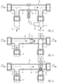
- the Figure 1 shows a schematic drinking water installation with several storey lines 2.1, 2.2, 2.3 and 2.4, which run horizontally and communicate via a vertical line section 4 with a transfer point 6, which - as usual - is immediately upstream of shut-off valves with water meters 8 in the direction of flow.
- the strands 2.1, 2.2, 2.3, 2.4 are provided with several ring lines 10, which are connected to the strand 2 via an inlet at reference number 14 and open into the strand 2 via a return line at reference number 16. Details of this design are given in EP 1 845 207 B1 of the applicant. A ring line flushing valve is also described therein, which is basically suitable for implementing the drinking water installation according to the invention.
- flow resistance elements are also usually provided between the inlet and the return, so that in the case of a branch flow, a ring flow is induced in the respective ring line 10 due to the pressure difference acting between the inlet 14 and the return 16. In this way, in the case of a branch flow, a parallel flow is produced both in the ring line 10 and in a branch section which is identified by reference numeral 12 and laid parallel to the respective ring line 10.
- each line 2 there is a flush valve 18.
- This flush valve 18 connects each line to a discharge section 20, which communicates with a wastewater line 26 via a central flush valve 22 and a free outlet 24.
- This wastewater line 26 discharges water into the municipal wastewater disposal network.
- Each ring main 10 forms at least one withdrawal point 28 in the form of a toilet, a hand wash basin, a shower or a bathtub.
- the embodiment of the drinking water installation according to the invention implements elements known from the prior art.
- the Figure 2 shows a first variant not according to the invention in the form of a uniform ring line flushing valve 30, which forms an inlet 14 and a return 16.
- the ring line flow is identified by reference numeral 32; the branch flow by reference numeral 34.
- a movable flow resistance element 36 is provided between the inlet 14 and the return 16.
- This flow resistance element 36 is only indicated schematically. It can be a nozzle-shaped flow resistance element 36, which causes a Venturi effect in the area of the return 16 due to the increase in speed of the line flow 34, so that the ring line flow 32 also flows into the line 2 due to a relative suction.
- the flow resistance element 36 is mechanically coupled to an expansion element 38, which is thermally conductively coupled to the water within the ring line 10 in the area of the return line 16.
- the variant shown is a ring line flushing valve 30 for a cold water system TWK. If the water temperature in the area of the expansion element 38 increases, the expansion of the expansion element 38 results in a feed of the flow resistance element 36 in the line section 12. This increases the resistance in the line section 12. As a result, more and more water is diverted into the ring line 10. The stale, heated water in the ring line 10 is replaced by fresh water. As a result, the expansion element becomes cooler. It contracts so that the flow resistance element 36 is retracted to its original position.
- the variant allows a self-regulating adjustment of the flow conditions in the line section 12 on the one hand and the ring line 10 on the other hand, so that at any time when there is a flow in the line 2 downstream of the shown embodiment of the ring line flushing valve 30, if there is stagnant water there, this is replaced, but if there is fresh water in the ring line 10, water can pass unhindered through the line section 12 so that the water can flow in the line 2 without significant pressure loss.
- FIG. 2 The embodiment of a ring line flushing valve 30 shown can be used for any of the Figure 1 shown ring lines can be implemented.
- FIG 3 shows a variant of a strand according to Figure 1 Identical components are marked with the same reference symbol.
- Each ring line flushing valve 30 is assigned an adjustable flow resistance element 36 between the inlet 14 and the return 16.
- the flow resistance element 36 is primarily set by an actuator 40 forming an actuator.
- Each actuator 40 is connected in terms of data to a central control device (not shown here), which also receives and processes the signals from the sensors explained below and the flushing valve(s) 18, 22.
- a temperature sensor 42 is mounted in the area of the return line 16.
- the arrangement of this temperature sensor 42 corresponds to the specification of the expansion element 38 according to the embodiment according to Figure 2
- the temperature sensor 42 detects the temperature of the water in the ring line 10 in the area of the return line 16. If the temperature becomes critical, the control device controls the actuator 40, which advances the flow resistance element 36 into the branch section 12, whereby a ring line flow is induced in the ring line 10.
- a pressure sensor 44 is implemented in the subsequent ring line flushing valve 30. This pressure sensor 44 records the pressure conditions in the ring line 10. If the pressure falls below a predetermined value, a ring line flow is concluded. This ring line flow can result from a presetting of the movable resistance element 36. This preset pressure difference is relatively small, but also leads to a ring line flow if there is a significant volume flow within the branch downstream of the corresponding ring line 10. If this does not occur, which is communicated to the control device via the measured pressure value in the ring line 10, the control device closes the flow resistance element 36 more strongly after a predetermined time, for example.
- the branch section 12 can also be completely relocated if necessary, so that if there is a flow in the branch 2 downstream of the corresponding ring line 10, a ring line flow is reliably induced in it.
- a volume flow sensor 46 is installed in the ring line 10 near the return line 16. This volume flow sensor 46 detects an actual ring line flow and reports its presence or absence to the control device, so that the control device sets the actuator 40 to the movable flow resistance element 36 in order to cause a flow through the ring line 10.
- the Figure 3 The last ring line 10 shown is either flowed through when water is taken from the said ring line, or when the flush valve 18 installed at the end of the rod 2 is activated.
- a volume flow sensor 48 and/or a temperature sensor 50 is arranged upstream of the flush valve 18 in the direction of flow, which indicate a flush cycle started by activating the flush valve 18 either after a volume flow has taken place, which is discharged into the waste water line 26, or due to the water temperature falling below a predetermined value, which indicates that the line 2 and the ring lines 10 connected to it need to be replaced with fresh water.
- a pressure sensor 51 can also be installed in the end of the line. The signal from such a sensor can prevent flushing if too low a pressure is detected in the end of the line. Since no extraction point is provided here, a low pressure is interpreted as an indication of too low a flow pressure at a downstream point where water is extracted. If the measured pressure is too low, it is concluded that there is insufficient flow pressure at the water extraction point.
- an optional circulation line 60 is shown, which is provided with a circulation pump 62. This is provided with a heat exchanger 64, which supplies heat to a DHW system or removes heat from a DHW system in order to set a certain target temperature in the system.
- the Figure 4 shows an alternative embodiment of a ring line flushing valve with a three-way ball valve 52, which can be set by motor to a ring flow position, a parallel flow position and a branch flow position.
- the branch section 12 is laid.
- the ring line 10 is, however, continuous as a bypass of the branch section 12.
- both the line section 12 and the ring line 10 are continuous.
- a static flow resistance element 54 within the line section 12 a ring line flow can be induced in a manner known per se parallel to the line flow.
- the line flow position compared to the position according to Figure 4 pivoted 90° anti-clockwise
- only the line section 12 is continuous. Flow through the ring line 10 is not possible, since it is routed through the three-way ball valve in the area of the return line 16.
- the Figure 5 shows a further embodiment of a ring line flushing valve 30, which has an electric motor as an actuator, which interacts with a flushing orifice 56, which can essentially prevent the line flow 34 and thus essentially block the line 2.
- the flushing orifice 56 can also allow a leakage flow as line flow 34 through the line section 12.
- the flushing orifice 56 is sealed in an opening of the return flow 16.
- an expansion element 38 is provided, which changes a regulating gap 58 within the flushing orifice, whereby a temperature-dependent regulation of the ring line flow 32 is possible.
- the flushing orifice 56 is penetrated by a bore that allows the branch flow 34 to flow through the flushing orifice 56 with a certain flow resistance. This flow resistance is adjusted in such a way that a ring line flow is induced when a significant amount of water is drawn downstream of the ring line flushing valve 30.
- This regulating gap 58 is usually designed in such a way that a leakage flow from the ring line 10 back into the branch 2 is possible in any position of the expansion element 38.
- a branch flow 34 is only permitted as a leakage flow.
- the main part of a water flow due to a downstream supply of water or due to the position of the flushing valve 18 or 22 causes a flow through the ring line, which is flushed in this way.
Landscapes
- Health & Medical Sciences (AREA)
- Life Sciences & Earth Sciences (AREA)
- Engineering & Computer Science (AREA)
- Hydrology & Water Resources (AREA)
- Public Health (AREA)
- Water Supply & Treatment (AREA)
- Domestic Plumbing Installations (AREA)
Claims (10)
- Installation d'eau potable comportant un point de raccordement pour de l'eau potable provenant d'un système d'alimentation en eau, et une ligne (2) à partir de laquelle s'étend une boucle (10) menant à au moins un point de prélèvement, dans laquelle la ligne (2) et la boucle (10) entre une entrée (14) dans la boucle (10) et un retour (16) de la boucle (10) dans la ligne (2) sont agencées en parallèle, dans laquelle l'installation d'eau potable comporte un actionneur (40) pour modifier les conditions d'écoulement dans la boucle (10), et un capteur (42, 44, 46, 48, 50, 51) pour détecter un paramètre de rinçage qui est couplé à l'actionneur (40) pour un positionnement en fonction du paramètre de rinçage, dans laquelle l'actionneur (40) modifie la résistance à l'écoulement dans la ligne (2) parallèle à la boucle (10) et est agencé dans ladite ligne (2), dans laquelle l'actionneur est positionné par un entraînement d'actionnement contrôlable (40), qui est relié pour la commande à un dispositif de commande qui traite un signal provenant d'un capteur (42, 44, 46, 48, 50, 51) comme paramètre de rinçage pour le positionnement de l'entraînement d'actionnement (40), caractérisée en ce qu'un capteur de pression (44, 51) est présent, dont le signal de capteur est traité dans le dispositif de commande de telle sorte que lors d'une perte de charge imputable au prélèvement d'eau potable à l'un des points de prélèvement de l'installation d'eau potable, un signal de capteur, qui est reconnu par le dispositif de commande comme un signal de capteur qui déclenche un processus de rinçage, suspend la commande de l'activation d'un cycle de rinçage, et le dispositif de commande est connecté en commande à une vanne de rinçage (18 ; 22), qui est située à l'extrémité d'une ligne (2) et par laquelle de l'eau potable provenant de l'installation d'eau potable est transférée vers un système d'eaux usées.
- Installation d'eau potable selon la revendication 1, caractérisée en ce que l'actionneur et le capteur sont constitués par un élément en matériau expansible (38) qui est couplé de manière thermoconductrice à l'eau potable présente dans la boucle (10) dans la zone du retour (16).
- Installation d'eau potable selon la revendication 1 ou 2, caractérisée en ce que le capteur (42, 44, 46) détecte un paramètre de fonctionnement de l'eau potable présente dans la boucle (10), et lorsque les conditions ne sont pas critiques dans la boucle (10), le dispositif de commande positionne l'actionneur (40) pour le réglage de conditions d'écoulement dans lesquelles un écoulement à travers la boucle (10) est au moins sensiblement suspendu, et lorsque les conditions dans la boucle (10) sont critiques, positionne l'actionneur (40) pour le réglage de conditions d'écoulement dans lesquelles un écoulement traverse la boucle (10) est possible.
- Installation d'eau potable selon la revendication 1 ou 2, caractérisée en ce que le capteur est un capteur de température (42) qui est couplé de manière thermoconductrice à l'eau potable présente dans la boucle (10) dans la zone du retour (16), et en ce que le dispositif de commande pilote l'actionneur quand une valeur seuil de température est dépassée de telle sorte qu'un écoulement à travers la boucle (10) soit possible, alors qu'autrement un écoulement à travers la boucle (10) est au moins sensiblement suspendu.
- Installation d'eau potable selon l'une des revendications 1 à 4, caractérisée par un capteur de débit (48) qui détermine le débit volumique dans la ligne en aval de la dernière boucle (10.3) et interagit avec le dispositif de commande de telle sorte que lorsqu'un volume de rinçage prédéterminé est atteint, la vanne de rinçage (18) est fermée.
- Installation d'eau potable selon l'une des revendications précédentes, caractérisée en ce que l'actionneur (40) règle le débit volumique dans la boucle (10) par rapport au débit volumique dans la ligne parallèle à celle-ci.
- Installation d'eau potable selon l'une des revendications précédentes, caractérisée en ce que l'actionneur (40) règle la résistance à l'écoulement dans la boucle (10) ou dans la ligne parallèle à celle-ci .
- Installation d'eau potable selon l'une des revendications précédentes, de préférence avec plusieurs boucles (10) connectées à la ligne (2), caractérisée en ce que le dispositif de commande comporte une mémoire pour enregistrer le volume de la boucle (10) et en ce que le dispositif de commande règle la durée d'un cycle de rinçage et/ou une position de l'actionneur en fonction du volume de la boucle à rincer (10) pour régler les conditions d'écoulement dans lesquelles un écoulement à travers la boucle à rincer est possible.
- Installation d'eau potable selon l'une des revendications précédentes, de préférence avec plusieurs boucles (10) connectées à la ligne (2), caractérisée en ce que le dispositif de commande comporte une mémoire pour enregistrer les débits partiels passant par la boucle (10) et par la section de ligne (12) d'une vanne de rinçage de boucle (30) associée à la boucle (10), et en ce que le dispositif de commande règle la durée d'un cycle de rinçage en fonction des débits partiels de ladite vanne de rinçage de boucle (30) qui est associée à la boucle à rincer (10).
- Installation d'eau potable selon l'une des revendications précédentes, caractérisée par une conduite de circulation (60) pourvue d'une pompe de circulation (62), qui s'étend depuis la ligne (2) en aval de la dernière boucle (10.3) et débouche dans la boucle (2) en amont de la première boucle (10).
Applications Claiming Priority (1)
| Application Number | Priority Date | Filing Date | Title |
|---|---|---|---|
| DE202021101228.5U DE202021101228U1 (de) | 2021-03-11 | 2021-03-11 | Trinkwasser-Installation |
Publications (2)
| Publication Number | Publication Date |
|---|---|
| EP4056768A1 EP4056768A1 (fr) | 2022-09-14 |
| EP4056768B1 true EP4056768B1 (fr) | 2024-09-25 |
Family
ID=75379099
Family Applications (1)
| Application Number | Title | Priority Date | Filing Date |
|---|---|---|---|
| EP22161519.8A Active EP4056768B1 (fr) | 2021-03-11 | 2022-03-11 | Installation d'eau potable |
Country Status (2)
| Country | Link |
|---|---|
| EP (1) | EP4056768B1 (fr) |
| DE (1) | DE202021101228U1 (fr) |
Families Citing this family (2)
| Publication number | Priority date | Publication date | Assignee | Title |
|---|---|---|---|---|
| DE102021119456A1 (de) | 2021-07-27 | 2023-02-02 | Hans Sasserath Gmbh & Co. Kg | Anschlussanordnung zum Anschließen einer Spülarmatur an eine Zirkulationsleitung |
| DE202024100015U1 (de) * | 2024-01-04 | 2025-04-14 | Grünbeck AG | Steuereinrichtung zur Steuerung einer Trinkwasserbehandlungsanlage |
Citations (1)
| Publication number | Priority date | Publication date | Assignee | Title |
|---|---|---|---|---|
| DE202009003135U1 (de) * | 2009-03-09 | 2010-09-02 | Gebr. Kemper Gmbh + Co. Kg | Trink- oder Brauchwassersystem |
Family Cites Families (6)
| Publication number | Priority date | Publication date | Assignee | Title |
|---|---|---|---|---|
| DE102006017807B4 (de) * | 2006-04-13 | 2013-10-24 | Gebr. Kemper Gmbh & Co. Kg Metallwerke | Trinkwassersystem sowie Verfahren zum Betrieb eines solchen Systems |
| DE202010003376U1 (de) | 2010-03-09 | 2011-08-01 | Gebrüder Kemper GmbH + Co Metallwerke | Trink- und Brauchwassersystem |
| DE102011010840B4 (de) * | 2011-02-10 | 2019-08-14 | Oventrop Gmbh & Co. Kg | Trink- oder Brauchwassersystem |
| EP3617569B1 (fr) | 2018-08-28 | 2021-02-17 | Georg Fischer JRG AG | Armature de raccordement ainsi que système de conduites d'eau |
| DE202018005578U1 (de) | 2018-11-30 | 2020-03-04 | Gebr. Kemper Gmbh + Co. Kg Metallwerke | Trink- und Brauchwassersystem |
| DE102019201263A1 (de) | 2019-01-31 | 2020-08-06 | Gebrüder Kemper Gmbh + Co. Kg Metallwerke | Trink- und Brauchwassersystem und Verfahren zum Spülen desselben |
-
2021
- 2021-03-11 DE DE202021101228.5U patent/DE202021101228U1/de active Active
-
2022
- 2022-03-11 EP EP22161519.8A patent/EP4056768B1/fr active Active
Patent Citations (1)
| Publication number | Priority date | Publication date | Assignee | Title |
|---|---|---|---|---|
| DE202009003135U1 (de) * | 2009-03-09 | 2010-09-02 | Gebr. Kemper Gmbh + Co. Kg | Trink- oder Brauchwassersystem |
Also Published As
| Publication number | Publication date |
|---|---|
| DE202021101228U1 (de) | 2021-03-22 |
| EP4056768A1 (fr) | 2022-09-14 |
Similar Documents
| Publication | Publication Date | Title |
|---|---|---|
| EP1887150B1 (fr) | Système d'eau potable et usée tout comme son procédé de fonctionnement | |
| EP3690151B1 (fr) | Système d'eau potable et d'eau sanitaire et son procédé de rinçage | |
| EP2365141B1 (fr) | Système d'eau sanitaire | |
| EP2895659B1 (fr) | Dispositif pour réaliser un rinçage hygiénique dans une installation hydraulique | |
| EP3580394B1 (fr) | Chasse d'eau pour un équipement sanitaire ainsi que chasse d'eau pour toilettes ou urinoir | |
| EP3321594B1 (fr) | Système d'eau pourvu d'un chauffe-eau instantané et d'une station de rinçage | |
| DE3622139C2 (fr) | ||
| EP4056768A1 (fr) | Installation d'eau potable | |
| EP2993271B1 (fr) | Dispositif de commande et système d'eau potable et/ou sanitaire ayant un tel dispositif de commande | |
| EP4007832B1 (fr) | Procédé de fonctionnement d'un système de circulation et système de circulation | |
| DE20301965U1 (de) | Steuervorrichtung für eine Solaranlage | |
| DE102004033307A1 (de) | Verfahren zum Betrieb einer zentralen Warmwasserversorgungsanlage in Gebäuden | |
| EP4137645B1 (fr) | Installation d'eau potable | |
| DE20120156U1 (de) | Steuereinrichtung für Warmwasserzirkulationspumpen | |
| DE102004033770A1 (de) | Vorrichtung zur Wasserzuteilung für eine Spüleinrichtung und Spülkasten | |
| DE202013104471U1 (de) | Vorrichtung zum schnellen Bereitstellen von erwärmtem Wasser | |
| EP4269882B1 (fr) | Système d'alimentation en eau chaude avec récupération de chaleur | |
| EP3670765B1 (fr) | Alimentation de chauffe-eau | |
| EP1385072A2 (fr) | Soupape de réglage | |
| EP2918738B1 (fr) | Dispositif de ventilation pour une colonne montante comprenant un dispositif de réduction de l'eau stagnante | |
| DE102014008319B4 (de) | Raumtemperatur-Regelung für eine Flächenheizung | |
| WO2025119433A2 (fr) | Procédé de mise à disposition d'eau potable, dispositif d'alimentation en eau potable et unité de commutation d'eau chaude et de rinçage | |
| AT500156B1 (de) | Verfahren zum betrieb einer zentralen warmwasserversorgungsanlage in gebäuden | |
| EP4737808A1 (fr) | Dispositif de transfert de chaleur | |
| WO2020001745A1 (fr) | Procédé pour faire fonctionner un système de circulation d'eau |
Legal Events
| Date | Code | Title | Description |
|---|---|---|---|
| PUAI | Public reference made under article 153(3) epc to a published international application that has entered the european phase |
Free format text: ORIGINAL CODE: 0009012 |
|
| STAA | Information on the status of an ep patent application or granted ep patent |
Free format text: STATUS: THE APPLICATION HAS BEEN PUBLISHED |
|
| AK | Designated contracting states |
Kind code of ref document: A1 Designated state(s): AL AT BE BG CH CY CZ DE DK EE ES FI FR GB GR HR HU IE IS IT LI LT LU LV MC MK MT NL NO PL PT RO RS SE SI SK SM TR |
|
| STAA | Information on the status of an ep patent application or granted ep patent |
Free format text: STATUS: REQUEST FOR EXAMINATION WAS MADE |
|
| 17P | Request for examination filed |
Effective date: 20230109 |
|
| RBV | Designated contracting states (corrected) |
Designated state(s): AL AT BE BG CH CY CZ DE DK EE ES FI FR GB GR HR HU IE IS IT LI LT LU LV MC MK MT NL NO PL PT RO RS SE SI SK SM TR |
|
| STAA | Information on the status of an ep patent application or granted ep patent |
Free format text: STATUS: EXAMINATION IS IN PROGRESS |
|
| 17Q | First examination report despatched |
Effective date: 20231212 |
|
| P01 | Opt-out of the competence of the unified patent court (upc) registered |
Effective date: 20240304 |
|
| GRAP | Despatch of communication of intention to grant a patent |
Free format text: ORIGINAL CODE: EPIDOSNIGR1 |
|
| STAA | Information on the status of an ep patent application or granted ep patent |
Free format text: STATUS: GRANT OF PATENT IS INTENDED |
|
| RIC1 | Information provided on ipc code assigned before grant |
Ipc: E03B 7/08 20060101ALI20240402BHEP Ipc: F24D 17/00 20220101ALI20240402BHEP Ipc: E03B 7/04 20060101AFI20240402BHEP |
|
| INTG | Intention to grant announced |
Effective date: 20240422 |
|
| GRAS | Grant fee paid |
Free format text: ORIGINAL CODE: EPIDOSNIGR3 |
|
| GRAA | (expected) grant |
Free format text: ORIGINAL CODE: 0009210 |
|
| STAA | Information on the status of an ep patent application or granted ep patent |
Free format text: STATUS: THE PATENT HAS BEEN GRANTED |
|
| AK | Designated contracting states |
Kind code of ref document: B1 Designated state(s): AL AT BE BG CH CY CZ DE DK EE ES FI FR GB GR HR HU IE IS IT LI LT LU LV MC MK MT NL NO PL PT RO RS SE SI SK SM TR |
|
| REG | Reference to a national code |
Ref country code: GB Ref legal event code: FG4D Free format text: NOT ENGLISH |
|
| REG | Reference to a national code |
Ref country code: CH Ref legal event code: EP |
|
| REG | Reference to a national code |
Ref country code: DE Ref legal event code: R096 Ref document number: 502022001724 Country of ref document: DE |
|
| REG | Reference to a national code |
Ref country code: IE Ref legal event code: FG4D Free format text: LANGUAGE OF EP DOCUMENT: GERMAN |
|
| REG | Reference to a national code |
Ref country code: LT Ref legal event code: MG9D |
|
| PG25 | Lapsed in a contracting state [announced via postgrant information from national office to epo] |
Ref country code: NO Free format text: LAPSE BECAUSE OF FAILURE TO SUBMIT A TRANSLATION OF THE DESCRIPTION OR TO PAY THE FEE WITHIN THE PRESCRIBED TIME-LIMIT Effective date: 20241225 |
|
| PG25 | Lapsed in a contracting state [announced via postgrant information from national office to epo] |
Ref country code: GR Free format text: LAPSE BECAUSE OF FAILURE TO SUBMIT A TRANSLATION OF THE DESCRIPTION OR TO PAY THE FEE WITHIN THE PRESCRIBED TIME-LIMIT Effective date: 20241226 Ref country code: FI Free format text: LAPSE BECAUSE OF FAILURE TO SUBMIT A TRANSLATION OF THE DESCRIPTION OR TO PAY THE FEE WITHIN THE PRESCRIBED TIME-LIMIT Effective date: 20240925 |
|
| PG25 | Lapsed in a contracting state [announced via postgrant information from national office to epo] |
Ref country code: BG Free format text: LAPSE BECAUSE OF FAILURE TO SUBMIT A TRANSLATION OF THE DESCRIPTION OR TO PAY THE FEE WITHIN THE PRESCRIBED TIME-LIMIT Effective date: 20240925 |
|
| PG25 | Lapsed in a contracting state [announced via postgrant information from national office to epo] |
Ref country code: LV Free format text: LAPSE BECAUSE OF FAILURE TO SUBMIT A TRANSLATION OF THE DESCRIPTION OR TO PAY THE FEE WITHIN THE PRESCRIBED TIME-LIMIT Effective date: 20240925 |
|
| PG25 | Lapsed in a contracting state [announced via postgrant information from national office to epo] |
Ref country code: RS Free format text: LAPSE BECAUSE OF FAILURE TO SUBMIT A TRANSLATION OF THE DESCRIPTION OR TO PAY THE FEE WITHIN THE PRESCRIBED TIME-LIMIT Effective date: 20241225 |
|
| REG | Reference to a national code |
Ref country code: NL Ref legal event code: MP Effective date: 20240925 |
|
| PG25 | Lapsed in a contracting state [announced via postgrant information from national office to epo] |
Ref country code: RS Free format text: LAPSE BECAUSE OF FAILURE TO SUBMIT A TRANSLATION OF THE DESCRIPTION OR TO PAY THE FEE WITHIN THE PRESCRIBED TIME-LIMIT Effective date: 20241225 Ref country code: NO Free format text: LAPSE BECAUSE OF FAILURE TO SUBMIT A TRANSLATION OF THE DESCRIPTION OR TO PAY THE FEE WITHIN THE PRESCRIBED TIME-LIMIT Effective date: 20241225 Ref country code: LV Free format text: LAPSE BECAUSE OF FAILURE TO SUBMIT A TRANSLATION OF THE DESCRIPTION OR TO PAY THE FEE WITHIN THE PRESCRIBED TIME-LIMIT Effective date: 20240925 Ref country code: GR Free format text: LAPSE BECAUSE OF FAILURE TO SUBMIT A TRANSLATION OF THE DESCRIPTION OR TO PAY THE FEE WITHIN THE PRESCRIBED TIME-LIMIT Effective date: 20241226 Ref country code: FI Free format text: LAPSE BECAUSE OF FAILURE TO SUBMIT A TRANSLATION OF THE DESCRIPTION OR TO PAY THE FEE WITHIN THE PRESCRIBED TIME-LIMIT Effective date: 20240925 Ref country code: BG Free format text: LAPSE BECAUSE OF FAILURE TO SUBMIT A TRANSLATION OF THE DESCRIPTION OR TO PAY THE FEE WITHIN THE PRESCRIBED TIME-LIMIT Effective date: 20240925 |
|
| PG25 | Lapsed in a contracting state [announced via postgrant information from national office to epo] |
Ref country code: NL Free format text: LAPSE BECAUSE OF FAILURE TO SUBMIT A TRANSLATION OF THE DESCRIPTION OR TO PAY THE FEE WITHIN THE PRESCRIBED TIME-LIMIT Effective date: 20240925 |
|
| PG25 | Lapsed in a contracting state [announced via postgrant information from national office to epo] |
Ref country code: PT Free format text: LAPSE BECAUSE OF FAILURE TO SUBMIT A TRANSLATION OF THE DESCRIPTION OR TO PAY THE FEE WITHIN THE PRESCRIBED TIME-LIMIT Effective date: 20250127 Ref country code: IS Free format text: LAPSE BECAUSE OF FAILURE TO SUBMIT A TRANSLATION OF THE DESCRIPTION OR TO PAY THE FEE WITHIN THE PRESCRIBED TIME-LIMIT Effective date: 20250125 |
|
| PG25 | Lapsed in a contracting state [announced via postgrant information from national office to epo] |
Ref country code: RO Free format text: LAPSE BECAUSE OF FAILURE TO SUBMIT A TRANSLATION OF THE DESCRIPTION OR TO PAY THE FEE WITHIN THE PRESCRIBED TIME-LIMIT Effective date: 20240925 Ref country code: SM Free format text: LAPSE BECAUSE OF FAILURE TO SUBMIT A TRANSLATION OF THE DESCRIPTION OR TO PAY THE FEE WITHIN THE PRESCRIBED TIME-LIMIT Effective date: 20240925 |
|
| PG25 | Lapsed in a contracting state [announced via postgrant information from national office to epo] |
Ref country code: ES Free format text: LAPSE BECAUSE OF FAILURE TO SUBMIT A TRANSLATION OF THE DESCRIPTION OR TO PAY THE FEE WITHIN THE PRESCRIBED TIME-LIMIT Effective date: 20240925 |
|
| PG25 | Lapsed in a contracting state [announced via postgrant information from national office to epo] |
Ref country code: EE Free format text: LAPSE BECAUSE OF FAILURE TO SUBMIT A TRANSLATION OF THE DESCRIPTION OR TO PAY THE FEE WITHIN THE PRESCRIBED TIME-LIMIT Effective date: 20240925 |
|
| PG25 | Lapsed in a contracting state [announced via postgrant information from national office to epo] |
Ref country code: PL Free format text: LAPSE BECAUSE OF FAILURE TO SUBMIT A TRANSLATION OF THE DESCRIPTION OR TO PAY THE FEE WITHIN THE PRESCRIBED TIME-LIMIT Effective date: 20240925 Ref country code: CZ Free format text: LAPSE BECAUSE OF FAILURE TO SUBMIT A TRANSLATION OF THE DESCRIPTION OR TO PAY THE FEE WITHIN THE PRESCRIBED TIME-LIMIT Effective date: 20240925 |
|
| PG25 | Lapsed in a contracting state [announced via postgrant information from national office to epo] |
Ref country code: SK Free format text: LAPSE BECAUSE OF FAILURE TO SUBMIT A TRANSLATION OF THE DESCRIPTION OR TO PAY THE FEE WITHIN THE PRESCRIBED TIME-LIMIT Effective date: 20240925 Ref country code: IT Free format text: LAPSE BECAUSE OF FAILURE TO SUBMIT A TRANSLATION OF THE DESCRIPTION OR TO PAY THE FEE WITHIN THE PRESCRIBED TIME-LIMIT Effective date: 20240925 |
|
| REG | Reference to a national code |
Ref country code: DE Ref legal event code: R097 Ref document number: 502022001724 Country of ref document: DE |
|
| PG25 | Lapsed in a contracting state [announced via postgrant information from national office to epo] |
Ref country code: DK Free format text: LAPSE BECAUSE OF FAILURE TO SUBMIT A TRANSLATION OF THE DESCRIPTION OR TO PAY THE FEE WITHIN THE PRESCRIBED TIME-LIMIT Effective date: 20240925 |
|
| PLBE | No opposition filed within time limit |
Free format text: ORIGINAL CODE: 0009261 |
|
| STAA | Information on the status of an ep patent application or granted ep patent |
Free format text: STATUS: NO OPPOSITION FILED WITHIN TIME LIMIT |
|
| 26N | No opposition filed |
Effective date: 20250626 |
|
| PG25 | Lapsed in a contracting state [announced via postgrant information from national office to epo] |
Ref country code: SE Free format text: LAPSE BECAUSE OF FAILURE TO SUBMIT A TRANSLATION OF THE DESCRIPTION OR TO PAY THE FEE WITHIN THE PRESCRIBED TIME-LIMIT Effective date: 20240925 |
|
| PG25 | Lapsed in a contracting state [announced via postgrant information from national office to epo] |
Ref country code: MC Free format text: LAPSE BECAUSE OF FAILURE TO SUBMIT A TRANSLATION OF THE DESCRIPTION OR TO PAY THE FEE WITHIN THE PRESCRIBED TIME-LIMIT Effective date: 20240925 |
|
| PG25 | Lapsed in a contracting state [announced via postgrant information from national office to epo] |
Ref country code: LU Free format text: LAPSE BECAUSE OF NON-PAYMENT OF DUE FEES Effective date: 20250311 |
|
| REG | Reference to a national code |
Ref country code: BE Ref legal event code: MM Effective date: 20250331 |
|
| PG25 | Lapsed in a contracting state [announced via postgrant information from national office to epo] |
Ref country code: HR Free format text: LAPSE BECAUSE OF FAILURE TO SUBMIT A TRANSLATION OF THE DESCRIPTION OR TO PAY THE FEE WITHIN THE PRESCRIBED TIME-LIMIT Effective date: 20240925 Ref country code: FR Free format text: LAPSE BECAUSE OF NON-PAYMENT OF DUE FEES Effective date: 20250331 |
|
| PG25 | Lapsed in a contracting state [announced via postgrant information from national office to epo] |
Ref country code: BE Free format text: LAPSE BECAUSE OF NON-PAYMENT OF DUE FEES Effective date: 20250331 |
|
| PG25 | Lapsed in a contracting state [announced via postgrant information from national office to epo] |
Ref country code: IE Free format text: LAPSE BECAUSE OF NON-PAYMENT OF DUE FEES Effective date: 20250311 |
|
| REG | Reference to a national code |
Ref country code: CH Ref legal event code: U11 Free format text: ST27 STATUS EVENT CODE: U-0-0-U10-U11 (AS PROVIDED BY THE NATIONAL OFFICE) Effective date: 20260401 |
|
| PGFP | Annual fee paid to national office [announced via postgrant information from national office to epo] |
Ref country code: DE Payment date: 20260326 Year of fee payment: 5 |
|
| PGFP | Annual fee paid to national office [announced via postgrant information from national office to epo] |
Ref country code: AT Payment date: 20260301 Year of fee payment: 5 |
|
| PG25 | Lapsed in a contracting state [announced via postgrant information from national office to epo] |
Ref country code: CY Free format text: LAPSE BECAUSE OF FAILURE TO SUBMIT A TRANSLATION OF THE DESCRIPTION OR TO PAY THE FEE WITHIN THE PRESCRIBED TIME-LIMIT Effective date: 20240925 |
|
| PG25 | Lapsed in a contracting state [announced via postgrant information from national office to epo] |
Ref country code: LT Free format text: LAPSE BECAUSE OF FAILURE TO SUBMIT A TRANSLATION OF THE DESCRIPTION OR TO PAY THE FEE WITHIN THE PRESCRIBED TIME-LIMIT Effective date: 20240925 |
|
| PG25 | Lapsed in a contracting state [announced via postgrant information from national office to epo] |
Ref country code: TR Free format text: LAPSE BECAUSE OF FAILURE TO SUBMIT A TRANSLATION OF THE DESCRIPTION OR TO PAY THE FEE WITHIN THE PRESCRIBED TIME-LIMIT Effective date: 20240925 |
|
| PGFP | Annual fee paid to national office [announced via postgrant information from national office to epo] |
Ref country code: CH Payment date: 20260401 Year of fee payment: 5 |