EP4057079A1 - Steuervorrichtung für ein uhrwerk mit taktiler rückmeldung und uhrwerk, insbesondere armbanduhr, mit einer solchen vorrichtung - Google Patents
Steuervorrichtung für ein uhrwerk mit taktiler rückmeldung und uhrwerk, insbesondere armbanduhr, mit einer solchen vorrichtung Download PDFInfo
- Publication number
- EP4057079A1 EP4057079A1 EP21161683.4A EP21161683A EP4057079A1 EP 4057079 A1 EP4057079 A1 EP 4057079A1 EP 21161683 A EP21161683 A EP 21161683A EP 4057079 A1 EP4057079 A1 EP 4057079A1
- Authority
- EP
- European Patent Office
- Prior art keywords
- control device
- elastic
- guide tube
- adjustment rod
- slider
- Prior art date
- Legal status (The legal status is an assumption and is not a legal conclusion. Google has not performed a legal analysis and makes no representation as to the accuracy of the status listed.)
- Granted
Links
Images
Classifications
-
- G—PHYSICS
- G04—HOROLOGY
- G04B—MECHANICALLY-DRIVEN CLOCKS OR WATCHES; MECHANICAL PARTS OF CLOCKS OR WATCHES IN GENERAL; TIME PIECES USING THE POSITION OF THE SUN, MOON OR STARS
- G04B3/00—Normal winding of clockworks by hand or mechanically; Winding up several mainsprings or driving weights simultaneously
- G04B3/04—Rigidly-mounted keys, knobs or crowns
- G04B3/046—Operation by rotation and axial movement with extra function of axial shift of operating element, e.g. crown combined with push button
-
- G—PHYSICS
- G04—HOROLOGY
- G04B—MECHANICALLY-DRIVEN CLOCKS OR WATCHES; MECHANICAL PARTS OF CLOCKS OR WATCHES IN GENERAL; TIME PIECES USING THE POSITION OF THE SUN, MOON OR STARS
- G04B3/00—Normal winding of clockworks by hand or mechanically; Winding up several mainsprings or driving weights simultaneously
- G04B3/04—Rigidly-mounted keys, knobs or crowns
- G04B3/048—Operation exclusively by axial movement of a push-button, e.g. for chronographs
-
- G—PHYSICS
- G04—HOROLOGY
- G04B—MECHANICALLY-DRIVEN CLOCKS OR WATCHES; MECHANICAL PARTS OF CLOCKS OR WATCHES IN GENERAL; TIME PIECES USING THE POSITION OF THE SUN, MOON OR STARS
- G04B27/00—Mechanical devices for setting the time indicating means
-
- G—PHYSICS
- G04—HOROLOGY
- G04B—MECHANICALLY-DRIVEN CLOCKS OR WATCHES; MECHANICAL PARTS OF CLOCKS OR WATCHES IN GENERAL; TIME PIECES USING THE POSITION OF THE SUN, MOON OR STARS
- G04B27/00—Mechanical devices for setting the time indicating means
- G04B27/008—Mechanical devices for setting the time indicating means with parts which are put together with the winding parts, but are functionally separate from them
-
- G—PHYSICS
- G04—HOROLOGY
- G04B—MECHANICALLY-DRIVEN CLOCKS OR WATCHES; MECHANICAL PARTS OF CLOCKS OR WATCHES IN GENERAL; TIME PIECES USING THE POSITION OF THE SUN, MOON OR STARS
- G04B27/00—Mechanical devices for setting the time indicating means
- G04B27/02—Mechanical devices for setting the time indicating means by making use of the winding means
- G04B27/06—Mechanical devices for setting the time indicating means by making use of the winding means with rocking bar
-
- G—PHYSICS
- G04—HOROLOGY
- G04B—MECHANICALLY-DRIVEN CLOCKS OR WATCHES; MECHANICAL PARTS OF CLOCKS OR WATCHES IN GENERAL; TIME PIECES USING THE POSITION OF THE SUN, MOON OR STARS
- G04B3/00—Normal winding of clockworks by hand or mechanically; Winding up several mainsprings or driving weights simultaneously
- G04B3/04—Rigidly-mounted keys, knobs or crowns
- G04B3/041—Construction of crowns for rotating movement; connection with the winding stem; winding stems
-
- G—PHYSICS
- G04—HOROLOGY
- G04B—MECHANICALLY-DRIVEN CLOCKS OR WATCHES; MECHANICAL PARTS OF CLOCKS OR WATCHES IN GENERAL; TIME PIECES USING THE POSITION OF THE SUN, MOON OR STARS
- G04B37/00—Cases
- G04B37/08—Hermetic sealing of openings, joints, passages or slits
- G04B37/10—Hermetic sealing of openings, joints, passages or slits of winding stems
- G04B37/106—Hermetic sealing of openings, joints, passages or slits of winding stems of push buttons
Definitions
- the invention relates to the field of watchmaking, and in particular watchmaking movement control devices for timepieces, such as watches.
- the invention relates in particular to a device for controlling a watch movement with tactile feedback and a timepiece, in particular a watch, comprising such a control device.
- control devices such as push-buttons or push-button crowns, allow the control and/or adjustment of mechanical or electronic watch movements arranged inside a case of a timepiece, for example a watch.
- control devices can be intended, for example, for winding, setting the time or adjusting any function of a watch movement.
- Prior art control devices are at least movable in translation relative to the case between an active, adjustment and/or control position, and an inactive, rest position.
- the control devices generally comprise a head extending radially outside the box so as to be able to be manipulated by a user.
- the head is connected to the adjustment rod, which is adapted to act, directly or indirectly, on the watch movement when said head moves.
- mechanical watch movement control devices actuate mobiles of said device when they move between their active and inactive positions, so that the user feels a tactile feedback in the form of a slight resistance.
- this resistance may not be sufficient to cause remarkable tactile feedback for the user, that is to say, he may not feel it.
- the invention meets this need by providing a solution for a watch movement control device providing tactile feedback to a user when the latter modifies the position of said control device, said tactile feedback being of sufficient intensity to be felt. by a user.
- the invention relates to a device for controlling a watch movement comprising, on the one hand, a first part comprising a sliding guide tube intended to be fixed relative to said watch movement, and, on the other hand, a second movable part slidably guided by the guide tube in a direction called the "axial direction", relative to said first part, between an active position in which it is able to be fixed, by means of an adjustment rod, to a component of the watch movement, and an inactive position in which said adjustment rod is intended to release the component from the watch movement.
- the second part comprises a head covering a reversible elastic fitting module fixed to the adjustment rod and arranged so as to occupy a state of rest when the second part occupies the active and inactive positions and being biased by the guide tube when the second part evolves between these positions.
- the second part goes against elastic interlocking forces during its change of position, which causes a feeling of tactile feedback to the user. and more precisely, a feeling of indexing, indicating to the user the change of position of the second part.
- the tactile feedback is of sufficient intensity to be felt by a user.
- the invention may also include one or more of the following characteristics, taken separately or in all technically possible combinations.
- the guide tube when it stresses the elastic fitting module, exerts, by a radial projection, a force going against an elastic return force in the radial direction, this force being at the origin of the elastic interlocking force.
- the radial projection is formed by a lip, for example a ring, arranged at one end of the guide tube.
- the guide tube has the shape of a stepped cylinder, comprising a first cylindrical portion, an outer peripheral surface of which is guided in translation by a peripheral wall of a blind cavity of the head, and comprising a second cylindrical portion, an inner peripheral surface of which is guided in translation around the adjustment rod.
- the guide tube comprises a shoulder between its two cylindrical portions, the first portion receiving an elastic member arranged to bear against said shoulder and the elastic fitting module, said member working in compression so as to generate a force tending to move the elastic fitting module away from the guide tube.
- the first portion of the guide tube comprises a recess receiving the elastic fitting module when the second part occupies the active position, said elastic fitting module being set back from said recess when the second part occupies the active position.
- the elastic fitting module is interposed between the adjustment rod and the head, so that the head is fixed to the adjustment rod by means of the elastic fitting module.
- the elastic interlocking module comprises a cage extending between two end walls connected to each other by a peripheral wall, the end walls being respectively fixed to the head and adjusting rod. Said cage receives an elastic element protruding through the peripheral wall, that is to say through said cage.
- the elastic element comprises at least one slider engaged in a through hole in the peripheral wall so as to extend beyond said cage, said at least one slider being adapted to translate in a direction perpendicular to the sliding direction of the adjustment rod and being subjected to an elastic return force tending to hold the slider in the through hole by an elastic member.
- the elastic element comprises a sole fixed to the peripheral wall, the elastic member being interposed between the sole and said slider and working in compression.
- the elastic element comprises two sliders respectively engaged in a through hole of the peripheral wall so as to extend beyond said cage, said sliders being adapted to translate in a direction perpendicular to the sliding direction of the adjusting rod and being subjected to an elastic return force tending to hold the slider in the through hole by an elastic member
- the elastic member is interposed between the sliders and works in compression.
- the slider has at its distal end a hemispherical shape against which the guide tube is intended to bear when the second part moves relative to the first part between the active positions and inactive.
- the at least one slider is formed by a ball.
- the present invention also relates to a timepiece comprising a control device as described above, a case in which a watch movement is housed, and through which said control device is inserted, the adjustment rod being connected to said watch movement.
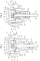
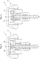
- the figures 1 and 2 show a preferred example of a device 10 for controlling a watch movement according to the present invention.
- the control device 10 can take the form of a push-piece crown, winding crown or any crown or button making it possible to act on the watch movement by pressure from the user.
- the control device 10 is intended to be engaged through a middle part of a case of a timepiece, in particular of a watch, in a manner known to those skilled in the art, in which the watch movement is housed. .
- control device 10 comprises a first part comprising a sliding guide tube 11 intended to be fixedly engaged in an orifice crossing extending radially in the middle.
- guide tube 11 is intended to be fixed relative to the watch movement.
- control device 10 comprises a second part 12 comprising an adjustment rod 120 extending through the guide tube 11, said rod being fixed, by one of its ends, to an elastic fitting module 130 reversible.
- the second part 12 also includes a head 140 covering the elastic fitting module 130, as described in more detail below.
- the adjustment rod 120 is slidably engaged in an axial direction through the guide tube 11, so that the second part 12 slides relative to the first part between an active position, represented on the figure 2 , in which the adjustment rod 120 is adapted to be integral with a component of the watch movement, and an inactive position, represented on the figure 1 , in which the adjustment rod 120 is able to release the component of the watch movement, that is to say that it is not integral with the latter.
- This change in position of the second part is caused by pressure on the head 140 by a user of the watch.
- the term “united” is understood to mean that two parts are kinematically connected together so that one can transmit a movement or a force to the other.
- the adjustment rod 120 is integral with the watch movement, it can act on the latter.
- control device 10 is configured so that the elastic fitting module 130 occupies a state of rest when the second part 12 occupies the inactive and active positions, and is stressed, that is to say constrained, by the guide tube 11 when the second part 12 moves between these positions.
- control device 10 causes the user, when he manipulates the second part 12 as described above, a feeling of tactile feedback, and more precisely, a frank feeling of indexing.
- the head 140 has a blind cavity 141 of substantially cylindrical shape, defined by a bottom wall 142 and by a peripheral wall 143.
- the cavity 141 receives the elastic interlocking module 130, the latter being fixed against the bottom wall 142, either by driving in or by gluing.
- the elastic casing module 130 comprises a cage of substantially cylindrical shape extending between two end walls 131 and 132 connected to each other by a peripheral wall 133.
- the cage is fixed to the head 140 by a first end wall 131, preferably having a cross-section of the shape complementary to that of the cavity 141, in particular that of the bottom wall 142 of said cavity 141.
- the cage is fixed, by a second end wall 132, to the adjustment rod 120.
- the elastic fitting module 130 is interposed between the adjustment rod 120 and the head 140, so that said head 140 is attached to the adjustment rod 120 through said module.
- the cage receives an elastic element extending radially through said cage and protruding, by at least one of its ends, through the peripheral wall 133.
- the elastic element comprises a sole 134 fixed to the peripheral wall 133 and a slider 135 movably engaged in translation in a through hole of the peripheral wall 133, so as to extend to the beyond said peripheral wall 133.
- the slider 135 and the sole 134 are diametrically opposed within the cage and said slider 135 is adapted to translate in a direction perpendicular to the sliding direction of the adjustment rod 120.
- the slider 135 and the sole 134 are connected to each other by an elastic member 136, which working in compression subjects the said slider 135 to an elastic restoring force tending to move it away from the sole 134, said restoring force elastic being at the origin of the elastic interlocking force.
- the slider 135 has a proximal end by which it is fixed to the elastic member 136 which is formed, in the preferred embodiment shown in the figures 1 and 2 , by a coil spring, and a distal end by which it protrudes beyond the cage.
- the slider 135 Between the distal end and the proximal end, the slider 135 comprises a radial flange 137 arranged in abutment against the wall peripheral 133 of the cage, when the elastic fitting module 130 occupies the state of rest. Another function of the collar 137 is to guide the slider 135 in translation, said collar 137 being fitted between the first and second end walls with a mechanical play allowing the slider 135 to move.
- the slider 135 is also guided in translation by a cylindrical portion by which it is engaged through the cage, and more particularly, through an orifice of the cage, the cross section of which has a complementary shape. from that of the cross section of the cylindrical portion.
- the slider 135 has at its distal end a hemispherical shape 138 against which the guide tube 11 is intended to bear when the second part 12 moves relative to the first part between the active and inactive positions, as described further below. detail below.
- the latter comprises, in place of the sole 134, another slider 135.
- the two sliders 135 are then intended to be acted upon simultaneously by the guide tube 11 when the second part 12 moves between the active and inactive positions.
- the sliders 135 is formed by a ball protruding beyond the cage, said ball having a diameter greater than that of the orifice through which they are engaged.
- the orifice may have means for retaining said ball, such as a reduction in section.
- the elastic element comprises, instead of the sole 134, another slider 135 and the sliders are formed by balls.
- the second end wall 132 of the cage comprises means for fixing to the adjustment rod 120.
- these fixing means can be formed by a central threaded hole with which one end, called the "proximal end”, cooperates by screwing. threaded, of the adjustment rod 120, or a central through bore with which cooperates in interference fit said proximal end of the adjustment rod 120.
- the adjustment rod 120 may, in addition, comprise at the level of the proximal end, an annular shoulder 121 intended to come into abutment against the second end wall 132. More particularly, the annular shoulder 121 is intended to abut against a boss extending around the tapped hole or the central bore of the cage.
- the adjustment rod 120 includes a distal stop 122, formed in the preferred embodiment of the invention by an elastic ring housed in an annular groove extending radially in said adjustment rod 120.
- the guide tube 11 bears against the distal stop when the second part 12 occupies the inactive position, as shown in the figure 1 .
- the guide tube 11 preferably has two guide zones in translation with respect to the second part 12.
- the guide tube 11 has the shape of a stepped cylinder comprising a first cylindrical portion and a second cylindrical portion. As illustrated in the figures, the first cylindrical portion has a larger diameter than the second cylindrical portion.
- the first cylindrical portion is engaged in the cavity 141 of the head 140, said first cylindrical portion comprising a peripheral wall 110 whose outer surface cooperates in sliding by sliding fit with the peripheral wall 143 of the head 140.
- the peripheral wall 110 may comprise an annular surface 111 provided to slide against the peripheral wall 143 of the head 140.
- the first cylindrical portion comprises a free end, opposite to the second cylindrical portion, comprising a radial projection 112 provided to exert a force against the slider 135 going against the elastic return force exerted by the elastic member 136, when the guide tube 11 biases the elastic fitting module 130.
- This force contributes to generating the elastic fitting forces.
- the radial projection 112 is formed by a lip extending inward from the first cylindrical portion.
- the “inside” of the first cylindrical portion is defined as the internal volume delimited by an internal surface of the peripheral wall 110.
- the internal surface of the peripheral wall 110 of the first cylindrical portion comprises an annular recess 113 facing the internal volume.
- This hollow 113 is intended to free up a sufficient volume to house the elastic fitting module 130 when the second part 12 occupies the active position, as represented on the figure 2 .
- the first cylindrical portion comprises a bottom wall 114 by which it is connected to the second cylindrical portion.
- Said bottom wall 114 forms a shoulder against which an elastic member 115 housed inside said first cylindrical portion is advantageously arranged to bear.
- the elastic member 115 is also arranged to bear against the elastic fitting module 130 and works in compression so as to generate a force tending to move the head 140 and the elastic fitting module 130 away from the guide tube 11.
- the second part 12 is driven towards the inactive position by the member elastic 115.
- the user accompanying the second part 12 in its movement to the inactive position he feels the elastic fitting forces when the radial projection 112 comes into contact against the slider 135 and punctually constrains the elastic member 136, and therefore it feels the sensation of tactile feedback.
- the second cylindrical portion is fitted around the adjusting rod 120, said second cylindrical portion comprising a peripheral wall 116 whose internal surface cooperates in sliding by sliding fit with said adjusting rod 120.
- the second cylindrical portion comprises a recess 117 receiving seals interposed between the peripheral wall of the second cylindrical portion and the adjustment rod 120.
- the second cylindrical portion comprises a free end opposite the first cylindrical portion, which is designed to bear against the distal stop of the adjustment rod 120 when the second part 12 occupies the inactive position.
Landscapes
- Physics & Mathematics (AREA)
- General Physics & Mathematics (AREA)
- Electric Clocks (AREA)
- Prostheses (AREA)
- Switches With Compound Operations (AREA)
- Electromechanical Clocks (AREA)
Priority Applications (5)
| Application Number | Priority Date | Filing Date | Title |
|---|---|---|---|
| EP21161683.4A EP4057079B1 (de) | 2021-03-10 | 2021-03-10 | Steuervorrichtung für ein uhrwerk mit taktiler rückmeldung und uhrwerk, insbesondere armbanduhr, mit einer solchen vorrichtung |
| US17/645,173 US11774908B2 (en) | 2021-03-10 | 2021-12-20 | Device for controlling a horological movement with tactile feedback and timepiece, in particular a watch, comprising such a device |
| JP2021208962A JP7304930B2 (ja) | 2021-03-10 | 2021-12-23 | 触覚的なフィードバックを有する、時計ムーブメントを制御するためのデバイス、およびそのようなデバイスを備える時計、特に腕時計 |
| KR1020220008665A KR102743516B1 (ko) | 2021-03-10 | 2022-01-20 | 촉각 피드백으로 오롤로지컬 무브먼트를 제어하는 장치 및 이러한 장치를 포함하는 특히 시계인 타임피스 |
| CN202210172147.3A CN115079546B (zh) | 2021-03-10 | 2022-02-24 | 具有触觉反馈的钟表机芯控制装置和包括该装置的钟表 |
Applications Claiming Priority (1)
| Application Number | Priority Date | Filing Date | Title |
|---|---|---|---|
| EP21161683.4A EP4057079B1 (de) | 2021-03-10 | 2021-03-10 | Steuervorrichtung für ein uhrwerk mit taktiler rückmeldung und uhrwerk, insbesondere armbanduhr, mit einer solchen vorrichtung |
Publications (2)
| Publication Number | Publication Date |
|---|---|
| EP4057079A1 true EP4057079A1 (de) | 2022-09-14 |
| EP4057079B1 EP4057079B1 (de) | 2023-10-18 |
Family
ID=74870665
Family Applications (1)
| Application Number | Title | Priority Date | Filing Date |
|---|---|---|---|
| EP21161683.4A Active EP4057079B1 (de) | 2021-03-10 | 2021-03-10 | Steuervorrichtung für ein uhrwerk mit taktiler rückmeldung und uhrwerk, insbesondere armbanduhr, mit einer solchen vorrichtung |
Country Status (5)
| Country | Link |
|---|---|
| US (1) | US11774908B2 (de) |
| EP (1) | EP4057079B1 (de) |
| JP (1) | JP7304930B2 (de) |
| KR (1) | KR102743516B1 (de) |
| CN (1) | CN115079546B (de) |
Cited By (1)
| Publication number | Priority date | Publication date | Assignee | Title |
|---|---|---|---|---|
| CN118169993A (zh) * | 2022-12-09 | 2024-06-11 | 伊塔瑞士钟表制造股份有限公司 | 适于抵抗震动的用于电子装置的控制模块 |
Citations (3)
| Publication number | Priority date | Publication date | Assignee | Title |
|---|---|---|---|---|
| EP1091269A1 (de) * | 1999-10-07 | 2001-04-11 | Perrenoud, Xavier | Uhrengehäuse |
| EP2607972B1 (de) * | 2011-12-22 | 2016-04-27 | The Swatch Group Research and Development Ltd. | Dichter Druckknopf für Armbanduhr |
| EP3245563B1 (de) * | 2015-01-14 | 2020-12-16 | Cartier International AG | Uhrengehäuse |
Family Cites Families (7)
| Publication number | Priority date | Publication date | Assignee | Title |
|---|---|---|---|---|
| JPS58148680U (ja) * | 1982-03-30 | 1983-10-05 | シチズン時計株式会社 | 時計のリユ−ズ構造 |
| JP5315024B2 (ja) | 2008-11-26 | 2013-10-16 | セイコーインスツル株式会社 | 携帯機器及び携帯時計 |
| JP5440886B2 (ja) * | 2011-12-19 | 2014-03-12 | カシオ計算機株式会社 | スイッチ装置及び腕時計 |
| JP2014089109A (ja) | 2012-10-30 | 2014-05-15 | Casio Comput Co Ltd | スイッチ装置 |
| JP5725065B2 (ja) * | 2013-03-21 | 2015-05-27 | カシオ計算機株式会社 | スイッチ装置および時計 |
| JP6350168B2 (ja) | 2014-09-24 | 2018-07-04 | カシオ計算機株式会社 | スイッチ装置及び時計 |
| CN104730903B (zh) * | 2015-03-24 | 2017-05-24 | 惠州Tcl移动通信有限公司 | 表壳组件及手表 |
-
2021
- 2021-03-10 EP EP21161683.4A patent/EP4057079B1/de active Active
- 2021-12-20 US US17/645,173 patent/US11774908B2/en active Active
- 2021-12-23 JP JP2021208962A patent/JP7304930B2/ja active Active
-
2022
- 2022-01-20 KR KR1020220008665A patent/KR102743516B1/ko active Active
- 2022-02-24 CN CN202210172147.3A patent/CN115079546B/zh active Active
Patent Citations (3)
| Publication number | Priority date | Publication date | Assignee | Title |
|---|---|---|---|---|
| EP1091269A1 (de) * | 1999-10-07 | 2001-04-11 | Perrenoud, Xavier | Uhrengehäuse |
| EP2607972B1 (de) * | 2011-12-22 | 2016-04-27 | The Swatch Group Research and Development Ltd. | Dichter Druckknopf für Armbanduhr |
| EP3245563B1 (de) * | 2015-01-14 | 2020-12-16 | Cartier International AG | Uhrengehäuse |
Cited By (1)
| Publication number | Priority date | Publication date | Assignee | Title |
|---|---|---|---|---|
| CN118169993A (zh) * | 2022-12-09 | 2024-06-11 | 伊塔瑞士钟表制造股份有限公司 | 适于抵抗震动的用于电子装置的控制模块 |
Also Published As
| Publication number | Publication date |
|---|---|
| JP7304930B2 (ja) | 2023-07-07 |
| EP4057079B1 (de) | 2023-10-18 |
| US11774908B2 (en) | 2023-10-03 |
| KR20220127134A (ko) | 2022-09-19 |
| US20220291630A1 (en) | 2022-09-15 |
| CN115079546B (zh) | 2024-01-19 |
| JP2022140285A (ja) | 2022-09-26 |
| KR102743516B1 (ko) | 2024-12-16 |
| CN115079546A (zh) | 2022-09-20 |
Similar Documents
| Publication | Publication Date | Title |
|---|---|---|
| EP1676177B1 (de) | Armbanduhr-drückstück-aufzieh-knopf-steuereinrichtung | |
| EP3451071B1 (de) | Vorrichtung mit drucktaste für uhr | |
| EP4198645B1 (de) | Multifunktionskorrekturvorrichtung für uhr, und uhr, die eine solche multifunktionskorrekturvorrichtung umfasst | |
| EP2065767A1 (de) | Steuervorrichtung mit Druckschalter | |
| CH712804B1 (fr) | Pièce d'horlogerie avec poussoir escamotable. | |
| EP3557336A1 (de) | Verriegelungssystem eines steuerelements einer uhr | |
| EP4057079B1 (de) | Steuervorrichtung für ein uhrwerk mit taktiler rückmeldung und uhrwerk, insbesondere armbanduhr, mit einer solchen vorrichtung | |
| EP4092490B1 (de) | Steuervorrichtung für ein uhrwerk mit taktiler rückmeldung und uhrwerk, insbesondere armbanduhr, mit einer solchen vorrichtung | |
| CH718416A2 (fr) | Dispositif de commande d'un mouvement horloger avec retour tactile et pièce d'horlogerie, notamment montre, comprenant un tel dispositif. | |
| CH706232A2 (fr) | Dispositif de commande et de réglage comportant une couronne et un poussoir coaxial. | |
| EP3742235B1 (de) | Druckknopfsystem und dieses umfassende uhr | |
| FR2724239A1 (fr) | Dispositif de poussoir etanche, notamment pour commander une piece d'horlogerie | |
| EP0027671B1 (de) | Vorrichtung zum Aufziehen und Stellen einer Uhr | |
| CH710271A2 (fr) | Organe de commande télescopique. | |
| CH718645A2 (fr) | Dispositif de commande d'un mouvement horloger avec retour tactile et pièce d'horlogerie, notamment montre, comprenant un tel dispositif. | |
| EP1676176B1 (de) | Steuerungseinrichtung mit ausklinkbarer krone für eine armbanduhr | |
| EP2141554A2 (de) | Drücker | |
| EP1091269A1 (de) | Uhrengehäuse | |
| CH716210A2 (fr) | Système de bouton-poussoir, et pièce d'horlogerie le comprenant. | |
| EP1730605A1 (de) | Korrekturmechanismus für eine uhr | |
| EP0957415A1 (de) | Drucktastenvorrichtung für Uhr,insbesondere Chronographuhr | |
| CH708126A2 (fr) | Joint, poussoir et couronne de pièce d'horlogerie. | |
| CH704691A1 (fr) | Bouton-poussoir à guidage amélioré. | |
| EP1554635B1 (de) | Betätigungsvorrichtung für uhren | |
| CH714112A2 (fr) | Dispositif à poussoir pour pièce d'horlogerie. |
Legal Events
| Date | Code | Title | Description |
|---|---|---|---|
| PUAI | Public reference made under article 153(3) epc to a published international application that has entered the european phase |
Free format text: ORIGINAL CODE: 0009012 |
|
| STAA | Information on the status of an ep patent application or granted ep patent |
Free format text: STATUS: THE APPLICATION HAS BEEN PUBLISHED |
|
| AK | Designated contracting states |
Kind code of ref document: A1 Designated state(s): AL AT BE BG CH CY CZ DE DK EE ES FI FR GB GR HR HU IE IS IT LI LT LU LV MC MK MT NL NO PL PT RO RS SE SI SK SM TR |
|
| STAA | Information on the status of an ep patent application or granted ep patent |
Free format text: STATUS: REQUEST FOR EXAMINATION WAS MADE |
|
| 17P | Request for examination filed |
Effective date: 20230314 |
|
| RBV | Designated contracting states (corrected) |
Designated state(s): AL AT BE BG CH CY CZ DE DK EE ES FI FR GB GR HR HU IE IS IT LI LT LU LV MC MK MT NL NO PL PT RO RS SE SI SK SM TR |
|
| P01 | Opt-out of the competence of the unified patent court (upc) registered |
Effective date: 20230611 |
|
| GRAP | Despatch of communication of intention to grant a patent |
Free format text: ORIGINAL CODE: EPIDOSNIGR1 |
|
| STAA | Information on the status of an ep patent application or granted ep patent |
Free format text: STATUS: GRANT OF PATENT IS INTENDED |
|
| INTG | Intention to grant announced |
Effective date: 20230728 |
|
| GRAS | Grant fee paid |
Free format text: ORIGINAL CODE: EPIDOSNIGR3 |
|
| GRAA | (expected) grant |
Free format text: ORIGINAL CODE: 0009210 |
|
| STAA | Information on the status of an ep patent application or granted ep patent |
Free format text: STATUS: THE PATENT HAS BEEN GRANTED |
|
| AK | Designated contracting states |
Kind code of ref document: B1 Designated state(s): AL AT BE BG CH CY CZ DE DK EE ES FI FR GB GR HR HU IE IS IT LI LT LU LV MC MK MT NL NO PL PT RO RS SE SI SK SM TR |
|
| REG | Reference to a national code |
Ref country code: GB Ref legal event code: FG4D Free format text: NOT ENGLISH |
|
| REG | Reference to a national code |
Ref country code: CH Ref legal event code: EP |
|
| REG | Reference to a national code |
Ref country code: IE Ref legal event code: FG4D Free format text: LANGUAGE OF EP DOCUMENT: FRENCH |
|
| REG | Reference to a national code |
Ref country code: DE Ref legal event code: R096 Ref document number: 602021005897 Country of ref document: DE |
|
| REG | Reference to a national code |
Ref country code: LT Ref legal event code: MG9D |
|
| REG | Reference to a national code |
Ref country code: NL Ref legal event code: MP Effective date: 20231018 |
|
| REG | Reference to a national code |
Ref country code: AT Ref legal event code: MK05 Ref document number: 1622981 Country of ref document: AT Kind code of ref document: T Effective date: 20231018 |
|
| PG25 | Lapsed in a contracting state [announced via postgrant information from national office to epo] |
Ref country code: NL Free format text: LAPSE BECAUSE OF FAILURE TO SUBMIT A TRANSLATION OF THE DESCRIPTION OR TO PAY THE FEE WITHIN THE PRESCRIBED TIME-LIMIT Effective date: 20231018 |
|
| PG25 | Lapsed in a contracting state [announced via postgrant information from national office to epo] |
Ref country code: GR Free format text: LAPSE BECAUSE OF FAILURE TO SUBMIT A TRANSLATION OF THE DESCRIPTION OR TO PAY THE FEE WITHIN THE PRESCRIBED TIME-LIMIT Effective date: 20240119 |
|
| PG25 | Lapsed in a contracting state [announced via postgrant information from national office to epo] |
Ref country code: IS Free format text: LAPSE BECAUSE OF FAILURE TO SUBMIT A TRANSLATION OF THE DESCRIPTION OR TO PAY THE FEE WITHIN THE PRESCRIBED TIME-LIMIT Effective date: 20240218 |
|
| PG25 | Lapsed in a contracting state [announced via postgrant information from national office to epo] |
Ref country code: LT Free format text: LAPSE BECAUSE OF FAILURE TO SUBMIT A TRANSLATION OF THE DESCRIPTION OR TO PAY THE FEE WITHIN THE PRESCRIBED TIME-LIMIT Effective date: 20231018 |
|
| PG25 | Lapsed in a contracting state [announced via postgrant information from national office to epo] |
Ref country code: AT Free format text: LAPSE BECAUSE OF FAILURE TO SUBMIT A TRANSLATION OF THE DESCRIPTION OR TO PAY THE FEE WITHIN THE PRESCRIBED TIME-LIMIT Effective date: 20231018 |
|
| PG25 | Lapsed in a contracting state [announced via postgrant information from national office to epo] |
Ref country code: ES Free format text: LAPSE BECAUSE OF FAILURE TO SUBMIT A TRANSLATION OF THE DESCRIPTION OR TO PAY THE FEE WITHIN THE PRESCRIBED TIME-LIMIT Effective date: 20231018 |
|
| PG25 | Lapsed in a contracting state [announced via postgrant information from national office to epo] |
Ref country code: LT Free format text: LAPSE BECAUSE OF FAILURE TO SUBMIT A TRANSLATION OF THE DESCRIPTION OR TO PAY THE FEE WITHIN THE PRESCRIBED TIME-LIMIT Effective date: 20231018 Ref country code: IS Free format text: LAPSE BECAUSE OF FAILURE TO SUBMIT A TRANSLATION OF THE DESCRIPTION OR TO PAY THE FEE WITHIN THE PRESCRIBED TIME-LIMIT Effective date: 20240218 Ref country code: GR Free format text: LAPSE BECAUSE OF FAILURE TO SUBMIT A TRANSLATION OF THE DESCRIPTION OR TO PAY THE FEE WITHIN THE PRESCRIBED TIME-LIMIT Effective date: 20240119 Ref country code: ES Free format text: LAPSE BECAUSE OF FAILURE TO SUBMIT A TRANSLATION OF THE DESCRIPTION OR TO PAY THE FEE WITHIN THE PRESCRIBED TIME-LIMIT Effective date: 20231018 Ref country code: BG Free format text: LAPSE BECAUSE OF FAILURE TO SUBMIT A TRANSLATION OF THE DESCRIPTION OR TO PAY THE FEE WITHIN THE PRESCRIBED TIME-LIMIT Effective date: 20240118 Ref country code: AT Free format text: LAPSE BECAUSE OF FAILURE TO SUBMIT A TRANSLATION OF THE DESCRIPTION OR TO PAY THE FEE WITHIN THE PRESCRIBED TIME-LIMIT Effective date: 20231018 Ref country code: PT Free format text: LAPSE BECAUSE OF FAILURE TO SUBMIT A TRANSLATION OF THE DESCRIPTION OR TO PAY THE FEE WITHIN THE PRESCRIBED TIME-LIMIT Effective date: 20240219 |
|
| PG25 | Lapsed in a contracting state [announced via postgrant information from national office to epo] |
Ref country code: SE Free format text: LAPSE BECAUSE OF FAILURE TO SUBMIT A TRANSLATION OF THE DESCRIPTION OR TO PAY THE FEE WITHIN THE PRESCRIBED TIME-LIMIT Effective date: 20231018 Ref country code: RS Free format text: LAPSE BECAUSE OF FAILURE TO SUBMIT A TRANSLATION OF THE DESCRIPTION OR TO PAY THE FEE WITHIN THE PRESCRIBED TIME-LIMIT Effective date: 20231018 Ref country code: PL Free format text: LAPSE BECAUSE OF FAILURE TO SUBMIT A TRANSLATION OF THE DESCRIPTION OR TO PAY THE FEE WITHIN THE PRESCRIBED TIME-LIMIT Effective date: 20231018 Ref country code: NO Free format text: LAPSE BECAUSE OF FAILURE TO SUBMIT A TRANSLATION OF THE DESCRIPTION OR TO PAY THE FEE WITHIN THE PRESCRIBED TIME-LIMIT Effective date: 20240118 Ref country code: LV Free format text: LAPSE BECAUSE OF FAILURE TO SUBMIT A TRANSLATION OF THE DESCRIPTION OR TO PAY THE FEE WITHIN THE PRESCRIBED TIME-LIMIT Effective date: 20231018 Ref country code: HR Free format text: LAPSE BECAUSE OF FAILURE TO SUBMIT A TRANSLATION OF THE DESCRIPTION OR TO PAY THE FEE WITHIN THE PRESCRIBED TIME-LIMIT Effective date: 20231018 |
|
| PG25 | Lapsed in a contracting state [announced via postgrant information from national office to epo] |
Ref country code: DK Free format text: LAPSE BECAUSE OF FAILURE TO SUBMIT A TRANSLATION OF THE DESCRIPTION OR TO PAY THE FEE WITHIN THE PRESCRIBED TIME-LIMIT Effective date: 20231018 |
|
| REG | Reference to a national code |
Ref country code: DE Ref legal event code: R097 Ref document number: 602021005897 Country of ref document: DE |
|
| PG25 | Lapsed in a contracting state [announced via postgrant information from national office to epo] |
Ref country code: CZ Free format text: LAPSE BECAUSE OF FAILURE TO SUBMIT A TRANSLATION OF THE DESCRIPTION OR TO PAY THE FEE WITHIN THE PRESCRIBED TIME-LIMIT Effective date: 20231018 |
|
| PG25 | Lapsed in a contracting state [announced via postgrant information from national office to epo] |
Ref country code: SK Free format text: LAPSE BECAUSE OF FAILURE TO SUBMIT A TRANSLATION OF THE DESCRIPTION OR TO PAY THE FEE WITHIN THE PRESCRIBED TIME-LIMIT Effective date: 20231018 |
|
| PG25 | Lapsed in a contracting state [announced via postgrant information from national office to epo] |
Ref country code: SM Free format text: LAPSE BECAUSE OF FAILURE TO SUBMIT A TRANSLATION OF THE DESCRIPTION OR TO PAY THE FEE WITHIN THE PRESCRIBED TIME-LIMIT Effective date: 20231018 Ref country code: SK Free format text: LAPSE BECAUSE OF FAILURE TO SUBMIT A TRANSLATION OF THE DESCRIPTION OR TO PAY THE FEE WITHIN THE PRESCRIBED TIME-LIMIT Effective date: 20231018 Ref country code: RO Free format text: LAPSE BECAUSE OF FAILURE TO SUBMIT A TRANSLATION OF THE DESCRIPTION OR TO PAY THE FEE WITHIN THE PRESCRIBED TIME-LIMIT Effective date: 20231018 Ref country code: IT Free format text: LAPSE BECAUSE OF FAILURE TO SUBMIT A TRANSLATION OF THE DESCRIPTION OR TO PAY THE FEE WITHIN THE PRESCRIBED TIME-LIMIT Effective date: 20231018 Ref country code: EE Free format text: LAPSE BECAUSE OF FAILURE TO SUBMIT A TRANSLATION OF THE DESCRIPTION OR TO PAY THE FEE WITHIN THE PRESCRIBED TIME-LIMIT Effective date: 20231018 Ref country code: DK Free format text: LAPSE BECAUSE OF FAILURE TO SUBMIT A TRANSLATION OF THE DESCRIPTION OR TO PAY THE FEE WITHIN THE PRESCRIBED TIME-LIMIT Effective date: 20231018 Ref country code: CZ Free format text: LAPSE BECAUSE OF FAILURE TO SUBMIT A TRANSLATION OF THE DESCRIPTION OR TO PAY THE FEE WITHIN THE PRESCRIBED TIME-LIMIT Effective date: 20231018 |
|
| PLBE | No opposition filed within time limit |
Free format text: ORIGINAL CODE: 0009261 |
|
| STAA | Information on the status of an ep patent application or granted ep patent |
Free format text: STATUS: NO OPPOSITION FILED WITHIN TIME LIMIT |
|
| 26N | No opposition filed |
Effective date: 20240719 |
|
| PG25 | Lapsed in a contracting state [announced via postgrant information from national office to epo] |
Ref country code: SI Free format text: LAPSE BECAUSE OF FAILURE TO SUBMIT A TRANSLATION OF THE DESCRIPTION OR TO PAY THE FEE WITHIN THE PRESCRIBED TIME-LIMIT Effective date: 20231018 |
|
| PG25 | Lapsed in a contracting state [announced via postgrant information from national office to epo] |
Ref country code: SI Free format text: LAPSE BECAUSE OF FAILURE TO SUBMIT A TRANSLATION OF THE DESCRIPTION OR TO PAY THE FEE WITHIN THE PRESCRIBED TIME-LIMIT Effective date: 20231018 |
|
| PG25 | Lapsed in a contracting state [announced via postgrant information from national office to epo] |
Ref country code: LU Free format text: LAPSE BECAUSE OF NON-PAYMENT OF DUE FEES Effective date: 20240310 |
|
| PG25 | Lapsed in a contracting state [announced via postgrant information from national office to epo] |
Ref country code: MC Free format text: LAPSE BECAUSE OF FAILURE TO SUBMIT A TRANSLATION OF THE DESCRIPTION OR TO PAY THE FEE WITHIN THE PRESCRIBED TIME-LIMIT Effective date: 20231018 |
|
| PG25 | Lapsed in a contracting state [announced via postgrant information from national office to epo] |
Ref country code: MC Free format text: LAPSE BECAUSE OF FAILURE TO SUBMIT A TRANSLATION OF THE DESCRIPTION OR TO PAY THE FEE WITHIN THE PRESCRIBED TIME-LIMIT Effective date: 20231018 Ref country code: LU Free format text: LAPSE BECAUSE OF NON-PAYMENT OF DUE FEES Effective date: 20240310 |
|
| REG | Reference to a national code |
Ref country code: BE Ref legal event code: MM Effective date: 20240331 |
|
| PG25 | Lapsed in a contracting state [announced via postgrant information from national office to epo] |
Ref country code: BE Free format text: LAPSE BECAUSE OF NON-PAYMENT OF DUE FEES Effective date: 20240331 |
|
| PG25 | Lapsed in a contracting state [announced via postgrant information from national office to epo] |
Ref country code: IE Free format text: LAPSE BECAUSE OF NON-PAYMENT OF DUE FEES Effective date: 20240310 |
|
| PG25 | Lapsed in a contracting state [announced via postgrant information from national office to epo] |
Ref country code: IE Free format text: LAPSE BECAUSE OF NON-PAYMENT OF DUE FEES Effective date: 20240310 Ref country code: BE Free format text: LAPSE BECAUSE OF NON-PAYMENT OF DUE FEES Effective date: 20240331 |
|
| PG25 | Lapsed in a contracting state [announced via postgrant information from national office to epo] |
Ref country code: CY Free format text: LAPSE BECAUSE OF FAILURE TO SUBMIT A TRANSLATION OF THE DESCRIPTION OR TO PAY THE FEE WITHIN THE PRESCRIBED TIME-LIMIT; INVALID AB INITIO Effective date: 20210310 |
|
| PG25 | Lapsed in a contracting state [announced via postgrant information from national office to epo] |
Ref country code: HU Free format text: LAPSE BECAUSE OF FAILURE TO SUBMIT A TRANSLATION OF THE DESCRIPTION OR TO PAY THE FEE WITHIN THE PRESCRIBED TIME-LIMIT; INVALID AB INITIO Effective date: 20210310 |
|
| PG25 | Lapsed in a contracting state [announced via postgrant information from national office to epo] |
Ref country code: FI Free format text: LAPSE BECAUSE OF FAILURE TO SUBMIT A TRANSLATION OF THE DESCRIPTION OR TO PAY THE FEE WITHIN THE PRESCRIBED TIME-LIMIT Effective date: 20231019 |
|
| PG25 | Lapsed in a contracting state [announced via postgrant information from national office to epo] |
Ref country code: TR Free format text: LAPSE BECAUSE OF FAILURE TO SUBMIT A TRANSLATION OF THE DESCRIPTION OR TO PAY THE FEE WITHIN THE PRESCRIBED TIME-LIMIT Effective date: 20231018 |
|
| REG | Reference to a national code |
Ref country code: CH Ref legal event code: U11 Free format text: ST27 STATUS EVENT CODE: U-0-0-U10-U11 (AS PROVIDED BY THE NATIONAL OFFICE) Effective date: 20260401 |
|
| PGFP | Annual fee paid to national office [announced via postgrant information from national office to epo] |
Ref country code: GB Payment date: 20260220 Year of fee payment: 6 |
|
| PGFP | Annual fee paid to national office [announced via postgrant information from national office to epo] |
Ref country code: DE Payment date: 20260219 Year of fee payment: 6 |
|
| PGFP | Annual fee paid to national office [announced via postgrant information from national office to epo] |
Ref country code: FR Payment date: 20260220 Year of fee payment: 6 |
|
| PGFP | Annual fee paid to national office [announced via postgrant information from national office to epo] |
Ref country code: CH Payment date: 20260401 Year of fee payment: 6 |