EP4057438A1 - Appareil et procédé de pliage de languette d'électrode - Google Patents
Appareil et procédé de pliage de languette d'électrode Download PDFInfo
- Publication number
- EP4057438A1 EP4057438A1 EP21740856.6A EP21740856A EP4057438A1 EP 4057438 A1 EP4057438 A1 EP 4057438A1 EP 21740856 A EP21740856 A EP 21740856A EP 4057438 A1 EP4057438 A1 EP 4057438A1
- Authority
- EP
- European Patent Office
- Prior art keywords
- electrode
- bending
- electrode tab
- electrode lead
- tab
- Prior art date
- Legal status (The legal status is an assumption and is not a legal conclusion. Google has not performed a legal analysis and makes no representation as to the accuracy of the status listed.)
- Pending
Links
Images




Classifications
-
- H—ELECTRICITY
- H01—ELECTRIC ELEMENTS
- H01M—PROCESSES OR MEANS, e.g. BATTERIES, FOR THE DIRECT CONVERSION OF CHEMICAL ENERGY INTO ELECTRICAL ENERGY
- H01M50/00—Constructional details or processes of manufacture of the non-active parts of electrochemical cells other than fuel cells, e.g. hybrid cells
- H01M50/50—Current conducting connections for cells or batteries
- H01M50/531—Electrode connections inside a battery casing
-
- H—ELECTRICITY
- H01—ELECTRIC ELEMENTS
- H01M—PROCESSES OR MEANS, e.g. BATTERIES, FOR THE DIRECT CONVERSION OF CHEMICAL ENERGY INTO ELECTRICAL ENERGY
- H01M50/00—Constructional details or processes of manufacture of the non-active parts of electrochemical cells other than fuel cells, e.g. hybrid cells
- H01M50/50—Current conducting connections for cells or batteries
- H01M50/531—Electrode connections inside a battery casing
- H01M50/533—Electrode connections inside a battery casing characterised by the shape of the leads or tabs
-
- B—PERFORMING OPERATIONS; TRANSPORTING
- B21—MECHANICAL METAL-WORKING WITHOUT ESSENTIALLY REMOVING MATERIAL; PUNCHING METAL
- B21D—WORKING OR PROCESSING OF SHEET METAL OR METAL TUBES, RODS OR PROFILES WITHOUT ESSENTIALLY REMOVING MATERIAL; PUNCHING METAL
- B21D37/00—Tools as parts of machines covered by this subclass
- B21D37/10—Die sets; Pillar guides
- B21D37/12—Particular guiding equipment, e.g. pliers; Special arrangements for interconnection or cooperation of dies
-
- B—PERFORMING OPERATIONS; TRANSPORTING
- B21—MECHANICAL METAL-WORKING WITHOUT ESSENTIALLY REMOVING MATERIAL; PUNCHING METAL
- B21D—WORKING OR PROCESSING OF SHEET METAL OR METAL TUBES, RODS OR PROFILES WITHOUT ESSENTIALLY REMOVING MATERIAL; PUNCHING METAL
- B21D5/00—Bending sheet metal along straight lines, e.g. to form simple curves
- B21D5/02—Bending sheet metal along straight lines, e.g. to form simple curves on press brakes without making use of clamping means
-
- B—PERFORMING OPERATIONS; TRANSPORTING
- B21—MECHANICAL METAL-WORKING WITHOUT ESSENTIALLY REMOVING MATERIAL; PUNCHING METAL
- B21D—WORKING OR PROCESSING OF SHEET METAL OR METAL TUBES, RODS OR PROFILES WITHOUT ESSENTIALLY REMOVING MATERIAL; PUNCHING METAL
- B21D5/00—Bending sheet metal along straight lines, e.g. to form simple curves
- B21D5/02—Bending sheet metal along straight lines, e.g. to form simple curves on press brakes without making use of clamping means
- B21D5/0209—Tools therefor
-
- H—ELECTRICITY
- H01—ELECTRIC ELEMENTS
- H01M—PROCESSES OR MEANS, e.g. BATTERIES, FOR THE DIRECT CONVERSION OF CHEMICAL ENERGY INTO ELECTRICAL ENERGY
- H01M50/00—Constructional details or processes of manufacture of the non-active parts of electrochemical cells other than fuel cells, e.g. hybrid cells
- H01M50/50—Current conducting connections for cells or batteries
- H01M50/531—Electrode connections inside a battery casing
- H01M50/536—Electrode connections inside a battery casing characterised by the method of fixing the leads to the electrodes, e.g. by welding
-
- H—ELECTRICITY
- H01—ELECTRIC ELEMENTS
- H01M—PROCESSES OR MEANS, e.g. BATTERIES, FOR THE DIRECT CONVERSION OF CHEMICAL ENERGY INTO ELECTRICAL ENERGY
- H01M50/00—Constructional details or processes of manufacture of the non-active parts of electrochemical cells other than fuel cells, e.g. hybrid cells
- H01M50/50—Current conducting connections for cells or batteries
- H01M50/531—Electrode connections inside a battery casing
- H01M50/54—Connection of several leads or tabs of plate-like electrode stacks, e.g. electrode pole straps or bridges
-
- B—PERFORMING OPERATIONS; TRANSPORTING
- B21—MECHANICAL METAL-WORKING WITHOUT ESSENTIALLY REMOVING MATERIAL; PUNCHING METAL
- B21D—WORKING OR PROCESSING OF SHEET METAL OR METAL TUBES, RODS OR PROFILES WITHOUT ESSENTIALLY REMOVING MATERIAL; PUNCHING METAL
- B21D11/00—Bending not restricted to forms of material mentioned in only one of groups B21D5/00, B21D7/00, B21D9/00; Bending not provided for in groups B21D5/00 - B21D9/00; Twisting
- B21D11/10—Bending specially adapted to produce specific articles, e.g. leaf springs
-
- B—PERFORMING OPERATIONS; TRANSPORTING
- B21—MECHANICAL METAL-WORKING WITHOUT ESSENTIALLY REMOVING MATERIAL; PUNCHING METAL
- B21D—WORKING OR PROCESSING OF SHEET METAL OR METAL TUBES, RODS OR PROFILES WITHOUT ESSENTIALLY REMOVING MATERIAL; PUNCHING METAL
- B21D5/00—Bending sheet metal along straight lines, e.g. to form simple curves
- B21D5/01—Bending sheet metal along straight lines, e.g. to form simple curves between rams and anvils or abutments
-
- Y—GENERAL TAGGING OF NEW TECHNOLOGICAL DEVELOPMENTS; GENERAL TAGGING OF CROSS-SECTIONAL TECHNOLOGIES SPANNING OVER SEVERAL SECTIONS OF THE IPC; TECHNICAL SUBJECTS COVERED BY FORMER USPC CROSS-REFERENCE ART COLLECTIONS [XRACs] AND DIGESTS
- Y02—TECHNOLOGIES OR APPLICATIONS FOR MITIGATION OR ADAPTATION AGAINST CLIMATE CHANGE
- Y02E—REDUCTION OF GREENHOUSE GAS [GHG] EMISSIONS, RELATED TO ENERGY GENERATION, TRANSMISSION OR DISTRIBUTION
- Y02E60/00—Enabling technologies; Technologies with a potential or indirect contribution to GHG emissions mitigation
- Y02E60/10—Energy storage using batteries
Definitions
- the present invention relates to an apparatus and method for bending an electrode tab, and more particularly, to an apparatus and method for bending an electrode tab, which are capable of V-forming an electrode tab while preventing the electrode tab from being damaged because it is unnecessary to allow a sharp knife to be in direct contact with the electrode tab.
- secondary batteries include nickelcadmium batteries, nickel-hydrogen batteries, lithium ion batteries, and lithium ion polymer batteries.
- Such a secondary battery is being applied to and used in small-sized products such as digital cameras, P-DVDs, MP3Ps, mobile phones, PDAs, portable game devices, power tools, E-bikes, and the like as well as large-sized products requiring high power such as electric vehicles and hybrid vehicles, power storage devices for storing surplus power or renewable energy, and backup power storage devices.
- a cathode hereinafter, referred to as a positive electrode
- a separator an anode
- an anode hereinafter, referred to as a negative electrode
- positive electrode active material slurry is applied to a positive electrode collector
- negative electrode active material slurry is applied to a negative electrode collector to manufacture a positive electrode and a negative electrode.
- separator is interposed and stacked between the manufactured positive electrode and the manufactured negative electrode, unit cells are formed. The unit cells are stacked on each other to form an electrode assembly. Also, when the electrode assembly is accommodated in a specific case, and an electrolyte is injected, the secondary battery is manufactured.
- Such a secondary battery is classified into a pouch type secondary battery and a can type secondary battery according to a material of a battery case accommodating an electrode assembly.
- the electrode assembly is accommodated in a pouch made of a flexible polymer material having a variable shape.
- an electrode assembly is accommodated in a case made of a metal or plastic material having a predetermined shape.
- the pouch type battery case is manufactured by performing drawing molding on a pouch film having flexibility to form a cup part.
- the drawing molding is performed by inserting a pouch film into a press and applying a pressure to the pouch film through a punch to stretch the pouch film.
- an electrode assembly is accommodated in an accommodation space of the cup part, and then, the battery case is folded to seal a sealing part, thereby manufacturing a secondary battery.
- a plurality of electrodes are stacked in one electrode assembly, and an electrode tab is formed on each of the electrodes to easily supply electricity generated from the electrodes to the outside.
- the electrode tabs positive electrode tabs are in contact with each other, and negative electrode tabs are in contact with each other. Then, the positive electrode tabs and the negative electrode tabs are connected to one positive electrode lead and one negative electrode lead, respectively. Also, in order to improve energy efficiency to volume by minimizing a space occupied by the electrode tab when the electrode tab is inserted into the pouch-type battery case, V-forming is performed in the electrode tab.
- the V-forming means bending of the electrode tab so that the electrode tab has a V shape as a whole.
- a sharp knife is in contact with a position to be bent of the electrode tab so as to perform the V-forming.
- damage occurs, such as cracks in the electrode tab, and a plated, delamination of a plated metal film, or even disconnection of the electrode tab.
- An object of the present invention for solving the above problem is to provide an apparatus and method for bending an electrode tab, which are capable of V-forming an electrode tab while preventing the electrode tab from being damaged because it is unnecessary to allow a sharp knife to be in direct contact with the electrode tab.
- a method for bending an electrode tab for achieving the above object includes: a step of stacking an electrode and an separator to manufacture an electrode assembly; a step of connecting an electrode lead to the electrode tab protruding from the electrode assembly; a step of primarily bending the electrode tab while a bending block disposed at one side of the electrode tab moves in a first direction that is directed toward the other side of the electrode tab; and a step of secondarily bending the electrode tab while the bending block moves in a second direction different from the first direction.
- the second direction may be perpendicular to the first direction and be directed toward the electrode assembly.
- the method may further include, after the step of secondarily bending the electrode tab, a step of bending the electrode lead while a roller moves from the electrode assembly in a third direction that is directed toward the electrode lead.
- the bending block may move until a first surface facing the first direction reaches a position corresponding to a position at which the electrode lead is bent in the step of bending the electrode lead.
- the roller may move in close contact with the first surface of the bending block with the electrode lead therebetween.
- the first surface of the bending block may be formed to be flat.
- the method may further include, after the step of connecting the electrode lead and before the step of primarily bending the electrode tab, a step of bending the electrode lead while the roller moves in a fourth direction that is directed toward the electrode lead.
- a second surface of the bending block which faces an opposite side of the electrode assembly, may be disposed at a position corresponding to a position at which the electrode lead is bent.
- the roller may move in close contact with the second surface of the bending block with the electrode lead therebetween.
- the second surface of the bending block may be formed to be flat.
- the bending block may move until a first surface facing the first direction is in contact with one surface of the electrode lead.
- an edge of the bending block which is in contact with the electrode tab or the electrode lead, may be chamfered or filleted.
- An apparatus for bending an electrode tab for achieving the above object includes: a bending block, which is disposed at one side of the electrode tab protruding from an electrode assembly to primarily bend the electrode tab while moving in a first direction that is directed toward the other side of the electrode tab and then to secondarily bend the electrode tab while moving in a second direction that is different from the first direction; and a roller configured to bend the electrode lead 12 while moving toward an electrode lead connected to the electrode tab.
- the roller may move after the bending block secondarily bends the electrode tab.
- a first surface of the bending block which faces the first direction, may be disposed at a position corresponding to a position at which the electrode lead is bent.
- the roller may move first before the bending block moves.
- a second surface of the bending block which faces an opposite side of the electrode assembly, may be disposed at a position corresponding to a position at which the electrode lead is bent.
- an edge of the bending block which is in contact with the electrode tab or the electrode lead, may be chamfered or filleted.
- the electrode tab may be V-formed while preventing the electrode tab from being damaged because it is unnecessary to allow the sharp knife to be in direct contact with the electrode tab.
- FIG. 1 is an assembled view of a secondary battery 1 according to an embodiment of the present invention.
- the pouch type secondary battery 1 includes an electrode assembly 10, in which electrodes such as a positive electrode and a negative electrode and separators are stacked, and a pouch type battery case 13 accommodating the electrode assembly 10 therein.
- the pouch type secondary battery 1 To manufacture the pouch type secondary battery 1, first, slurry in which an electrode active material, a binder, and a plasticizer are mixed with each other is applied to a positive electrode collector and a negative electrode collector to manufacture electrodes such as a positive electrode and a negative electrode. The electrodes are stacked on both sides of a separator to manufacture the electrode assembly 10 having a predetermined shape. Then, the electrode assembly 10 is inserted into the battery case 13, and the battery case 13 is sealed after injecting an electrolyte therein.
- the electrode assembly 10 may be a stacked structure including two types of electrodes such as a positive electrode and a negative electrode and a separator disposed between the electrodes to insulate the electrodes from each other or disposed at a left or right side of one electrode.
- the stacked structure may have various shapes without being limited in shape.
- the cathode and the anode each of which has a predetermined standard, may be stacked with the separator therebetween, or the stacked structure may be wound in the form of a jelly roll.
- Each of the two types of electrodes, i.e., the positive electrode and the negative electrode has a structure in which active material slurry is applied to the electrode collector having a metal foil or metal mesh shape.
- the slurry may be usually formed by agitating a granular active material, an auxiliary conductor, a binder, and a plasticizer with a solvent added. The solvent may be removed in the subsequent process.
- the electrode assembly 10 includes the electrode tabs 11.
- the electrode tabs 11 are respectively connected to a positive electrode and a negative electrode of the electrode assembly 10 to protrude to the outside of the electrode assembly 10, thereby providing a path, through which electrons are moved, between the inside and outside of the electrode assembly 10.
- An electrode collector of the electrode assembly 10 is constituted by a portion coated with an electrode active material and a distal end, on which the electrode active material is not applied, i.e., a non-coating portion.
- each of the electrode tabs 11 may be formed by cutting the non-coating portion or by connecting a separate conductive member to the non-coating portion through ultrasonic welding.
- the electrode tabs 11 may protrude from one side of the electrode assembly 10 in the same direction, but the present invention is not limited thereto.
- the electrode tabs 11 may protrude in directions different from each other.
- the electrode lead 12 that supplies electricity to the outside of the secondary battery 1 is connected to the electrode tab 11 through spot welding. Also, a portion of the electrode lead 12 is surrounded by an insulating part 14.
- the insulation part 14 may be disposed to be limited within a sealing part 134, at which an upper case 131 and a lower case 132 of the battery case 13 are thermally fused, so that the electrode lead 12 is bonded to the battery case 13. Also, electricity generated from the electrode assembly 10 may be prevented from flowing to the battery case 13 through the electrode lead 12, and the sealing of the battery case 13 may be maintained.
- the insulation part 14 may be made of a nonconductor having non-conductivity, which is not electrically conductive.
- the present invention is not limited thereto.
- various members may be used as the insulation part 14 as long as the members are capable of insulating the electrode lead 12.
- the electrode lead 12 includes a positive electrode lead 121 having one end connected to a positive electrode tab 111 to extend in a direction in which the positive electrode tab 111 protrudes and a negative electrode lead 122 having one end connected to a negative electrode tab 112 to extend in a direction in which the negative electrode tab 112 protrudes.
- a positive electrode lead 121 having one end connected to a positive electrode tab 111 to extend in a direction in which the positive electrode tab 111 protrudes
- a negative electrode lead 122 having one end connected to a negative electrode tab 112 to extend in a direction in which the negative electrode tab 112 protrudes.
- all of the other ends of the positive electrode lead 121 and the negative electrode lead 122 protrude to the outside of the battery case 13.
- electricity generated in the electrode assembly 10 may be supplied to the outside.
- each of the positive electrode tab 111 and the negative electrode tab 112 is formed to protrude in various directions, each of the positive electrode lead 121 and the negative electrode lead 122 may extend in various directions.
- the positive electrode lead 121 and the negative electrode lead 122 may be made of materials different from each other. That is, the cathode lead 121 may be made of the same material as the cathode collector, i.e., an aluminum (Al) material, and the anode lead 122 may be made of the same material as the anode collector, i.e., a copper (Cu) material or a copper material coated with nickel (Ni). Also, a portion of the electrode lead 12, which protrudes to the outside of the battery case 13, may be provided as a terminal part and electrically connected to an external terminal.
- Al aluminum
- the anode lead 122 may be made of the same material as the anode collector, i.e., a copper (Cu) material or a copper material coated with nickel (Ni).
- a portion of the electrode lead 12, which protrudes to the outside of the battery case 13 may be provided as a terminal part and electrically connected to an external terminal.
- the battery case 13 is a pouch made of a material having flexibility, which accommodates the electrode assembly 10 therein.
- a pouch film 135 having flexibility is drawn by using a punch or the like, a portion of the pouch film 135 is stretched to form a cup part 133 including a pocket-shaped accommodation space 1331, thereby manufacturing the battery case 13.
- the battery case 13 accommodates the electrode assembly 10 so that a portion of the electrode lead 12, i.e., the terminal part is exposed and then is sealed.
- the battery case 13 includes the upper case 131 and the lower case 132.
- An accommodation space 1331 in which a cup part 133 is formed to accommodate the electrode assembly 10 may be provided in the lower case 132, and upper case 131 may cover an upper side of the accommodation space 1331 so that the electrode assembly 10 is not separated to the outside of the battery case 13. Also, the sealing part 134 is sealed to seal the accommodation space 1331.
- the cup part 133 having the accommodation part 1331 may be formed in the upper case 131 to accommodate the electrode assembly 10 in the upper portion.
- one side of the upper case 131 and one side of the lower case 132 may be connected to each other.
- the present invention is not limited thereto.
- the upper case 131 and the lower case 132 may be separately manufactured to be separated from each other.
- the electrode assembly 10 When an electrode lead 12 is connected to the electrode tab 11 of the electrode assembly 10, and the insulation part 14 is provided on a portion of the electrode lead 12, the electrode assembly 10 may be accommodated in the accommodation space 1331 provided in the cup part 133 of the lower case 132, and the upper case 131 may cover the accommodation space from the upper side. Also, the electrolyte is injected, and the sealing part 134 extending outward from edges of the upper case 131 and the lower case 132 is sealed. The electrolyte may move lithium ions generated by electrochemical reaction of the electrode during charging and discharging of the secondary battery 1.
- the electrolyte may include a non-aqueous organic electrolyte that is a mixture of a lithium salt and a high-purity organic solvent or a polymer using a polymer electrolyte.
- the pouch type secondary battery 1 may be manufactured through the above-described method.
- FIG. 2 is a flowchart illustrating a method for bending the electrode tab 11 according to an embodiment of the present invention.
- the electrode tab since a bending block 21 linearly moves in two directions to bend the electrode tab 11, the electrode tab may be V-formed while preventing the electrode tab from being damaged because it is unnecessary to allow the sharp knife to be in direct contact with the electrode tab.
- a method for bending the electrode tab 11 includes: a step of stacking an electrode and an separator to manufacture an electrode assembly 10; a step of connecting an electrode lead 12 to the electrode tab 11 protruding from the electrode assembly 10; a step of primarily bending the electrode tab 11 while a bending block 21 disposed at one side of the electrode tab 11 moves in a first direction that is directed toward the other side of the electrode tab 11; and a step of secondarily bending the electrode tab 11 while the bending block 21 moves in a second direction different from the first direction.
- the method may further include, after the step of secondarily bending the electrode tab 11, a step of bending the electrode lead 12 while a roller 22 moves from the electrode assembly 10 in a third direction that is directed toward the electrode lead 12.
- the bending block 21, which is disposed at one side of the electrode tab 11 protruding from the electrode assembly 10 to primarily bend the electrode tab 11 while moving in the first direction that is directed toward the other side of the electrode tab 11 and then to secondarily bend the electrode tab 11 while moving in the second direction that is different from the first direction; and the roller 22 which bends the electrode lead 12 while moving toward the electrode lead 12 connected to the electrode tab 11. Also, the roller 22 may move after the bending block 21 secondly bends the electrode tab 11.
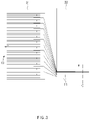
- FIG. 3 is a schematic view illustrating a state in which the plurality of electrode tabs 11 are in contact with each other according to an embodiment of the present invention.
- electrodes including a plurality of positive electrodes and negative electrodes and separators are alternately stacked to manufacture an electrode assembly 10 (S201). Also, in order to easily supply electricity generated from the electrodes to the outside, an electrode tab 11 is formed for each of the electrodes.
- the electrode tab 11 is formed to protrude outward from one side of the electrode assembly 10 and includes a positive electrode tab 111 protruding from the positive electrode and a negative electrode tab 112 protruding from the negative electrode.
- a plurality of electrode tabs 11 may also be formed.
- the electrode tabs 11 allow the positive electrode tabs 111 to contact each other so that the positive electrode tabs 111 are connected to each other and allow the negative electrode tabs 112 to contact each other so that the negative electrode tabs 112 are connected to each other.
- an electrode tab press 32 may press remaining electrode tabs 11 downward toward the electrode tab 11 disposed at the lowermost end to bend the electrode tabs 11 so that the electrode tabs 11 are in contact with each other.
- the present invention is not limited thereto.
- the electrode tab press 32 may press remaining electrode tabs 11 upward toward the electrode tab 11 disposed at the uppermost end to bend the electrode tabs 11 so that the electrode tabs 11 are in contact with each other.
- an electrode assembly fixing part 31 may press and fix the electrode assembly 10. Furthermore, even if the step of bending the electrode tab 11 and the electrode lead 12 is performed later, the electrode assembly fixing part 31 may press and fix the electrode assembly 10. After the plurality of electrode tabs 11 are in contact with each other and are arranged side by side, the electrode tabs 11 are cut along a cutting line C.
- FIG. 4 is a schematic view illustrating a state in which the plurality of electrode tabs are connected to each other according to an embodiment of the present invention.
- the plurality of electrode tabs 11 to be welded are mounted on a welding surface of an anvil 34, and then, as illustrated in FIG. 4 , a pressure is applied to the electrode tabs 11 using a welding surface of a horn 33.
- a plurality of protrusions are continuously arranged at a fixed order on the welding surface of the horn 33.
- the plurality of protrusions are embedded in the plurality of electrode tabs 11 to form patterns that are recessed in a shape corresponding to each of the protrusions in the outermost surface of the electrode tabs 11.
- vibration energy of the horn 33 and the anvil 34 is converted into thermal energy by friction to perform the welding.
- FIG. 5 is a schematic view illustrating a state in which the electrode lead 12 is connected to the electrode tabs 11 according to an embodiment of the present invention.
- one end of the electrode lead 12 is connected to the electrode tabs 11 (S202).
- laser welding may be performed on the electrode tabs 11 and the electrode lead 12 using a laser generator 35 as illustrated in FIG. 5 . That is, when the positive electrode tabs 111 are connected to each other, one end of the positive electrode lead 121 is connected to one surface of the positive electrode tab 111 through the laser welding, and when the negative electrode tabs 112 are connected to each other, one end of the negative electrode lead 122 is connected to one surface of the negative electrode tab 112 through the laser welding.
- FIG. 6 is a schematic view illustrating a state in which the bending block primarily bends the electrode tabs according to an embodiment of the present invention.
- the bending block 21 disposed at one side of the electrode tabs 11 moves in the first direction that is directed toward the other side of the electrode tabs 11 to primarily bend the electrode tabs 11 (S203).
- the electrode assembly 10 is disposed horizontally on the ground, the bending block 21 is disposed below the electrode tabs 11, and the first direction is upward.
- the bending block 21 may be disposed above the electrode tabs 11, and the first direction may be downward, and furthermore, if the electrode assembly 10 is disposed perpendicular to the ground, the first direction may be left to right, or right to left.
- a first surface 211 that faces the first direction i.e., the upward direction pushes the electrode tab 11 upward.
- the electrode tab 11 is bent to be inclined, and if the bending block 21 continuously moves upward, the inclination of the electrode tab 11 further increases.
- the bending block 21 continuously move upward until the first surface 211 reaches a position corresponding to a position at which the electrode lead 12 is to be bent later. Also, when the first surface 211 reaches the position corresponding to the position at which the electrode lead 12 is bent, the movement of the bending block 21 may be completed and stopped without moving any more.
- an edge of the bending block 21 may be in contact with the electrode tab 11 or the electrode lead 12. However, if the edge is sharp, there may still be a problem of damage such as an occurrence of cracking of the electrode tab 11 or the electrode lead 12 or delamination of a plated metal film.
- the edge of the bent block 21, which is in contact with the electrode tab 11 or the electrode lead 12 may be chamfered or filleted.
- FIG. 7 is a schematic view illustrating a state in which the bending block secondarily bends the electrode tabs according to an embodiment of the present invention.
- the moving direction may be changed, and the bending block 21 may move in the second direction different from the first direction.
- the bending block 21 secondarily bends the electrode tabs 11 (S204).
- the second direction will be described as being perpendicular to the first direction and as a direction that is directed toward the electrode assembly 10. This is for convenience of description and is not intended to limit the scope of rights. That is, the present invention is not limited thereto.
- the second direction includes various directions as long as the electrode tab 11 is capable of being secondarily bent, such as a diagonal direction between the first direction and the direction directed toward the electrode assembly 10.
- the electrode tab 11 may be V-formed while preventing the electrode tab 11 from being damaged because it is unnecessary to allow the sharp knife to be in direct contact with the electrode tab 11.
- FIG. 8 is a schematic view illustrating a state in which the roller bends the electrode lead according to an embodiment of the present invention.
- the roller 22 moves from the electrode assembly 10 to the electrode lead 12 in the third direction to bend the electrode lead 12 (S205). That is, according to an embodiment of the present invention, the roller 22 moves after the bending block 21 secondarily bends the electrode tab 11.
- the third direction may be a direction that is opposite to the second direction, is perpendicular to the first direction, and faces the opposite side of the electrode assembly 10.
- the first surface 211 of the bending block 21 is disposed at the position corresponding to the position at which the electrode lead 12 is bent. Therefore, when the roller 22 moves, it is preferable to move in close contact with the first surface 211 of the bending block 21 with the electrode lead 12 therebetween.
- the first surface 211 of the bending block 21 may be formed to be flat, and thus, the roller 22 may easily come into close contact with the first surface 211 with the electrode lead 12 therebetween.
- the electrode lead 12 is made of a metal as described above, the electrode lead 12 may have elasticity to some extent. Accordingly, after the roller 22 moves in the third direction, and the bending of the electrode lead 12 is completed, the electrode lead 12 may not be maintained to be in close contact with the first surface 211, but be inclined at a predetermined inclination. Thus, the roller 22 may be quite large and heavy. Furthermore, the roller 22 includes a heating coil to apply heat and a pressure to the electrode lead 12 together.
- FIG. 9 is a flowchart illustrating a method for bending an electrode tab according to another embodiment of the present invention.
- a method for bending the electrode tab 11 includes: a step of stacking an electrode and an separator to manufacture an electrode assembly 10; a step of connecting an electrode lead 12 to the electrode tab 11 protruding from the electrode assembly 10; a step of primarily bending the electrode tab 11 while a bending block 21 disposed at one side of the electrode tab 11 moves to the other side of the electrode tab 11; and a step of secondarily bending the electrode tab 11 while the bending block 21 moves toward the electrode tab 11.
- the method may further include, after the step of connecting the electrode lead 12 and before the step of primarily bending the electrode tab 11, a step of bending the electrode lead 12 while the roller 22a moves toward the electrode lead 12.
- an apparatus for bending an electrode tab which performs the method for bending the electrode tab 11, includes: the bending block 21, which is disposed at one side of the electrode tab 11 protruding from the electrode assembly 10 to primarily bend the electrode tab 11 while moving toward the other side of the electrode tab 11 and then to secondarily bend the electrode tab 11 while moving toward the electrode tab 11; and the roller 22a which bends the electrode lead 12 while moving toward the electrode lead 12 connected to the electrode tab 11.d 12 connected to the electrode tab 11 and bending the electrode lead 12.
- the roller 22a may move first before the bending block 21 moves.
- FIG. 10 is a schematic view illustrating a state in which the roller 22a bends the electrode lead 12 according to another embodiment of the present invention.
- the roller 22a moves in a fourth direction toward the electrode lead 12 to bend the electrode lead 12 (S903). That is, according to another embodiment of the present invention, the roller 22a moves first before the bending block 21 moves.
- the fourth direction may be a direction opposite to the first direction in which the bending block 21 moves to primarily bend the electrode tab 11 later.
- a second surface 212 facing an opposite side of the electrode assembly 10 is disposed at a position corresponding to a position at which the electrode lead 12 is bent. Therefore, when the roller 22a moves, it is preferable to move in close contact with the second surface 212 of the bending block 21 with the electrode lead 12 therebetween.
- the second surface 212 of the bending block 21 may be formed to be flat, and thus, the roller 22a may easily come into close contact with the second surface 212 with the electrode lead 12 therebetween.
- FIG. 11 is a schematic view illustrating a state in which the bending block 21 primarily bends the electrode tabs 11 according to another embodiment of the present invention.
- the bending block 21 disposed at one side of the electrode tabs 11 moves in a first direction that is directed toward the other side of the electrode tabs 11 to primarily bend the electrode tabs 11 (S904).
- the first direction will be described as being upward.
- a first surface 211 that faces the first direction i.e., the upward direction pushes the electrode tab 11 upward.
- the electrode tab 11 is bent to be inclined, and if the bending block 21 continuously moves upward, the inclination of the electrode tab 11 further increases.
- the bending block 21 continuously moves upward until the first surface 211 is in contact with one surface of the electrode lead 12. Also, when the first surface 211 is in contact with one surface of the electrode lead 12, the movement of the bending block 21 may be completed and stopped without moving any more.
- FIG. 12 is a schematic view illustrating a state in which the bending block secondarily bends the electrode tabs according to another embodiment of the present invention.
- the moving direction may be changed, and the bending block 21 may move in the second direction different from the first direction. Also, as illustrated in FIG. 12 , the bending block 21 secondarily bends the electrode tabs 11 (S905).
- the second direction will be described as being perpendicular to the first direction and as a direction that is directed toward the electrode assembly 10.
- the electrode tab 11 may be V-formed while preventing the electrode tab 11 from being damaged because it is unnecessary to allow the sharp knife to be in direct contact with the electrode tab 11.
- Electrode assembly 11 Battery case 12: Electrode lead 13: Battery case 14: Insulating part 21: Bending block 22: Roller 31: Electrode assembly fixing part 32: Electrode tab press 33: Horn 34: Anvil 35: Laser generator 111: Positive electrode tab 112: Negative electrode tab electrode lead 121: Positive 122: Negative electrode lead 131: Upper case 132: Lower case 133: Cup part 134: Sealing part 211: First surface 212: Second surface 1331: Accommodation space
Landscapes
- Chemical & Material Sciences (AREA)
- Chemical Kinetics & Catalysis (AREA)
- Electrochemistry (AREA)
- General Chemical & Material Sciences (AREA)
- Engineering & Computer Science (AREA)
- Mechanical Engineering (AREA)
- Connection Of Batteries Or Terminals (AREA)
Applications Claiming Priority (2)
| Application Number | Priority Date | Filing Date | Title |
|---|---|---|---|
| KR1020200005638A KR102751962B1 (ko) | 2020-01-15 | 2020-01-15 | 전극 탭 절곡 장치 및 방법 |
| PCT/KR2021/000348 WO2021145624A1 (fr) | 2020-01-15 | 2021-01-11 | Appareil et procédé de pliage de languette d'électrode |
Publications (2)
| Publication Number | Publication Date |
|---|---|
| EP4057438A1 true EP4057438A1 (fr) | 2022-09-14 |
| EP4057438A4 EP4057438A4 (fr) | 2023-09-06 |
Family
ID=76863218
Family Applications (1)
| Application Number | Title | Priority Date | Filing Date |
|---|---|---|---|
| EP21740856.6A Pending EP4057438A4 (fr) | 2020-01-15 | 2021-01-11 | Appareil et procédé de pliage de languette d'électrode |
Country Status (6)
| Country | Link |
|---|---|
| US (1) | US20220416374A1 (fr) |
| EP (1) | EP4057438A4 (fr) |
| JP (1) | JP7436116B2 (fr) |
| KR (1) | KR102751962B1 (fr) |
| CN (1) | CN114788084A (fr) |
| WO (1) | WO2021145624A1 (fr) |
Cited By (2)
| Publication number | Priority date | Publication date | Assignee | Title |
|---|---|---|---|---|
| WO2024251949A1 (fr) * | 2023-06-09 | 2024-12-12 | Northvolt Ab | Appareil et procédé de mise en forme par enlèvement de matière de languettes d'électrode |
| EP4571909A1 (fr) * | 2023-12-14 | 2025-06-18 | Customcells Holding GmbH | Procédé de fabrication d'un dispositif de stockage d'énergie |
Families Citing this family (13)
| Publication number | Priority date | Publication date | Assignee | Title |
|---|---|---|---|---|
| US11804639B2 (en) * | 2020-07-23 | 2023-10-31 | GM Global Technology Operations LLC | Multistage plunger systems and methods for forming battery cell tabs |
| EP4362211A4 (fr) * | 2021-10-05 | 2025-05-21 | LG Energy Solution, Ltd. | Ensemble électrode, son procédé de fabrication et cellule de batterie le comprenant |
| WO2023096469A1 (fr) | 2021-11-29 | 2023-06-01 | 주식회사 엘지에너지솔루션 | Appareil de soudage de languette d'électrode, procédé de soudage de languette d'électrode et batterie secondaire |
| KR102803517B1 (ko) * | 2022-05-24 | 2025-05-08 | 삼성에스디아이 주식회사 | 이차전지 |
| KR20230173971A (ko) * | 2022-06-20 | 2023-12-27 | 주식회사 엘지에너지솔루션 | 이차 전지의 제조 장치 및 이차 전지의 제조 방법 |
| KR20240010880A (ko) * | 2022-07-18 | 2024-01-25 | 주식회사 엘지에너지솔루션 | 이차 전지의 제조 장치 및 이차 전지의 제조 방법 |
| KR20240097207A (ko) * | 2022-12-20 | 2024-06-27 | 주식회사 엘지에너지솔루션 | 이차 전지 및 그 제조 방법 |
| CN115832210A (zh) * | 2022-12-20 | 2023-03-21 | 东莞新能源科技有限公司 | 一种电芯、电池及用电设备 |
| CN116242718B (zh) * | 2023-03-24 | 2025-07-04 | 上海先导慧能技术有限公司 | 极片柔韧性测试方法及测试设备 |
| CN116900123B (zh) * | 2023-09-12 | 2023-12-08 | 河南鑫泉能源科技有限公司 | 一种折弯装置 |
| KR20250135565A (ko) * | 2024-03-06 | 2025-09-15 | 삼성에스디아이 주식회사 | 이차 전지 제조 장치 및 이차 전지 제조 방법 |
| WO2026010266A1 (fr) * | 2024-07-03 | 2026-01-08 | 삼성전자 주식회사 | Batterie et dispositif électronique comprenant celle-ci |
| KR20260034416A (ko) * | 2024-09-04 | 2026-03-11 | 삼성에스디아이 주식회사 | 이차 전지, 이의 제조 장치 및 이의 제조 방법 |
Family Cites Families (16)
| Publication number | Priority date | Publication date | Assignee | Title |
|---|---|---|---|---|
| AU473224B2 (en) * | 1973-05-15 | 1976-06-17 | John Lysaght (Australia) Limited | Stamp forming articles from plate material |
| JPH09239444A (ja) * | 1996-03-13 | 1997-09-16 | Araco Corp | プレス成形方法及びプレス成形機 |
| JP2000243371A (ja) | 1999-02-24 | 2000-09-08 | Matsushita Electric Ind Co Ltd | 電池パック用接続端子 |
| JP2003142067A (ja) | 2001-10-31 | 2003-05-16 | Mitsubishi Cable Ind Ltd | シート状電池 |
| JP5157500B2 (ja) * | 2008-02-06 | 2013-03-06 | ソニー株式会社 | 非水電解質電池およびその製造方法 |
| JP5357799B2 (ja) * | 2010-02-09 | 2013-12-04 | 三菱重工業株式会社 | 二次電池、二次電池の製造装置および製造方法 |
| JP2011210662A (ja) * | 2010-03-30 | 2011-10-20 | Sanyo Electric Co Ltd | 積層式電池 |
| JP5844052B2 (ja) * | 2011-02-04 | 2016-01-13 | 三洋電機株式会社 | 積層式電池およびその製造方法 |
| KR101884410B1 (ko) * | 2012-08-07 | 2018-08-02 | 에스케이이노베이션 주식회사 | 전지팩 |
| KR101374849B1 (ko) * | 2012-09-11 | 2014-03-19 | 주식회사 루트제이드 | 벤딩부를 구비하는 이차전지용 케이스 |
| JP6274034B2 (ja) | 2014-06-30 | 2018-02-07 | 株式会社豊田自動織機 | 蓄電装置 |
| KR101731146B1 (ko) | 2014-07-11 | 2017-04-27 | 주식회사 엘지화학 | 전극 조립체의 복수개의 전극 탭과 전극 리드의 연결부의 포밍 방법 및 이를 이용하여 제조된 이차 전지 |
| KR101675763B1 (ko) * | 2016-07-15 | 2016-11-14 | 주식회사 정운 | 헤드레스트 스테이로드의 2단 성형방법 |
| KR102119535B1 (ko) * | 2017-01-18 | 2020-06-05 | 주식회사 엘지화학 | 전극조립체의 외면에 대면하여 위치하는 전극리드를 포함하는 전지셀 |
| CN207547344U (zh) * | 2017-12-01 | 2018-06-29 | 北京华特时代电动汽车技术有限公司 | 用于电芯的极耳折弯装置 |
| KR20190084765A (ko) * | 2018-01-09 | 2019-07-17 | 주식회사 엘지화학 | 전극 탭-리드 결합부에 적용된 플라스틱 부재를 포함하는 전극조립체 및 이를 포함하는 이차전지 |
-
2020
- 2020-01-15 KR KR1020200005638A patent/KR102751962B1/ko active Active
-
2021
- 2021-01-11 WO PCT/KR2021/000348 patent/WO2021145624A1/fr not_active Ceased
- 2021-01-11 CN CN202180007133.XA patent/CN114788084A/zh active Pending
- 2021-01-11 JP JP2022533602A patent/JP7436116B2/ja active Active
- 2021-01-11 US US17/780,298 patent/US20220416374A1/en active Pending
- 2021-01-11 EP EP21740856.6A patent/EP4057438A4/fr active Pending
Cited By (2)
| Publication number | Priority date | Publication date | Assignee | Title |
|---|---|---|---|---|
| WO2024251949A1 (fr) * | 2023-06-09 | 2024-12-12 | Northvolt Ab | Appareil et procédé de mise en forme par enlèvement de matière de languettes d'électrode |
| EP4571909A1 (fr) * | 2023-12-14 | 2025-06-18 | Customcells Holding GmbH | Procédé de fabrication d'un dispositif de stockage d'énergie |
Also Published As
| Publication number | Publication date |
|---|---|
| EP4057438A4 (fr) | 2023-09-06 |
| JP7436116B2 (ja) | 2024-02-21 |
| KR102751962B1 (ko) | 2025-01-10 |
| KR20210092094A (ko) | 2021-07-23 |
| JP2023504558A (ja) | 2023-02-03 |
| US20220416374A1 (en) | 2022-12-29 |
| CN114788084A (zh) | 2022-07-22 |
| WO2021145624A1 (fr) | 2021-07-22 |
Similar Documents
| Publication | Publication Date | Title |
|---|---|---|
| EP4057438A1 (fr) | Appareil et procédé de pliage de languette d'électrode | |
| US12476308B2 (en) | Battery case for secondary battery and pouch type secondary battery | |
| US8815426B2 (en) | Prismatic sealed secondary cell and method of manufacturing the same | |
| US12308392B2 (en) | Apparatus and method for manufacturing secondary battery | |
| KR102797474B1 (ko) | 이차 전지용 전지 케이스 및 파우치 형 이차 전지 | |
| US11817559B2 (en) | Apparatus and method for manufacturing secondary battery | |
| US20260045577A1 (en) | Pouch Type Battery Case and Pouch Type Secondary Battery | |
| CN104412409A (zh) | 二次电池 | |
| KR20210061113A (ko) | 전극 조립체 및 그의 제조 방법 | |
| KR102704540B1 (ko) | 이차 전지용 전지 케이스 및 파우치 형 이차 전지 | |
| CN113875043A (zh) | 二次电池 | |
| KR20220011030A (ko) | 이차 전지의 제조 방법 및 가압 패드 | |
| US12394816B2 (en) | Method for manufacturing electrode lead | |
| KR20200099392A (ko) | 이차 전지 및 전지 모듈 | |
| EP3958343B1 (fr) | Compartiment de batterie pour batterie secondaire et batterie secondaire de type poche | |
| KR20210037460A (ko) | 이차 전지용 전지 케이스 및 그의 제조 방법 | |
| KR20210098756A (ko) | 이차 전지용 전지 케이스 및 이차 전지 | |
| KR20060010658A (ko) | 권취형 전극 조립체 및 이를 구비하는 원통형 리튬 이차전지 | |
| US20250210826A1 (en) | Battery | |
| KR102833816B1 (ko) | 전극 리드, 그의 제조 방법 및 파우치 형 이차 전지 | |
| KR102689324B1 (ko) | 이차 전지용 전지 케이스 및 파우치 형 이차 전지 | |
| KR20210029611A (ko) | 이차 전지용 전지 케이스 및 파우치 형 이차 전지 |
Legal Events
| Date | Code | Title | Description |
|---|---|---|---|
| STAA | Information on the status of an ep patent application or granted ep patent |
Free format text: STATUS: THE INTERNATIONAL PUBLICATION HAS BEEN MADE |
|
| PUAI | Public reference made under article 153(3) epc to a published international application that has entered the european phase |
Free format text: ORIGINAL CODE: 0009012 |
|
| STAA | Information on the status of an ep patent application or granted ep patent |
Free format text: STATUS: REQUEST FOR EXAMINATION WAS MADE |
|
| 17P | Request for examination filed |
Effective date: 20220610 |
|
| AK | Designated contracting states |
Kind code of ref document: A1 Designated state(s): AL AT BE BG CH CY CZ DE DK EE ES FI FR GB GR HR HU IE IS IT LI LT LU LV MC MK MT NL NO PL PT RO RS SE SI SK SM TR |
|
| DAV | Request for validation of the european patent (deleted) | ||
| DAX | Request for extension of the european patent (deleted) | ||
| REG | Reference to a national code |
Ref country code: DE Ref legal event code: R079 Free format text: PREVIOUS MAIN CLASS: H01M0050531000 Ipc: H01M0050533000 |
|
| A4 | Supplementary search report drawn up and despatched |
Effective date: 20230804 |
|
| RIC1 | Information provided on ipc code assigned before grant |
Ipc: B21D 11/10 20060101ALN20230731BHEP Ipc: B21D 5/01 20060101ALN20230731BHEP Ipc: B21D 37/12 20060101ALI20230731BHEP Ipc: B21D 5/02 20060101ALI20230731BHEP Ipc: H01M 50/54 20210101ALI20230731BHEP Ipc: H01M 50/536 20210101ALI20230731BHEP Ipc: H01M 50/533 20210101AFI20230731BHEP |