EP4058657B1 - Couronne d'aubes fixes avec éléments d'usure - Google Patents
Couronne d'aubes fixes avec éléments d'usure Download PDFInfo
- Publication number
- EP4058657B1 EP4058657B1 EP20828833.2A EP20828833A EP4058657B1 EP 4058657 B1 EP4058657 B1 EP 4058657B1 EP 20828833 A EP20828833 A EP 20828833A EP 4058657 B1 EP4058657 B1 EP 4058657B1
- Authority
- EP
- European Patent Office
- Prior art keywords
- inner ring
- guide vane
- ring
- wear
- wear elements
- Prior art date
- Legal status (The legal status is an assumption and is not a legal conclusion. Google has not performed a legal analysis and makes no representation as to the accuracy of the status listed.)
- Active
Links
Images


Classifications
-
- F—MECHANICAL ENGINEERING; LIGHTING; HEATING; WEAPONS; BLASTING
- F01—MACHINES OR ENGINES IN GENERAL; ENGINE PLANTS IN GENERAL; STEAM ENGINES
- F01D—NON-POSITIVE DISPLACEMENT MACHINES OR ENGINES, e.g. STEAM TURBINES
- F01D9/00—Stators
- F01D9/02—Nozzles; Nozzle boxes; Stator blades; Guide conduits, e.g. individual nozzles
- F01D9/04—Nozzles; Nozzle boxes; Stator blades; Guide conduits, e.g. individual nozzles forming ring or sector
- F01D9/042—Nozzles; Nozzle boxes; Stator blades; Guide conduits, e.g. individual nozzles forming ring or sector fixing blades to stators
-
- F—MECHANICAL ENGINEERING; LIGHTING; HEATING; WEAPONS; BLASTING
- F01—MACHINES OR ENGINES IN GENERAL; ENGINE PLANTS IN GENERAL; STEAM ENGINES
- F01D—NON-POSITIVE DISPLACEMENT MACHINES OR ENGINES, e.g. STEAM TURBINES
- F01D25/00—Component parts, details, or accessories, not provided for in, or of interest apart from, other groups
- F01D25/24—Casings; Casing parts, e.g. diaphragms, casing fastenings
- F01D25/246—Fastening of diaphragms or stator-rings
-
- F—MECHANICAL ENGINEERING; LIGHTING; HEATING; WEAPONS; BLASTING
- F01—MACHINES OR ENGINES IN GENERAL; ENGINE PLANTS IN GENERAL; STEAM ENGINES
- F01D—NON-POSITIVE DISPLACEMENT MACHINES OR ENGINES, e.g. STEAM TURBINES
- F01D9/00—Stators
- F01D9/02—Nozzles; Nozzle boxes; Stator blades; Guide conduits, e.g. individual nozzles
- F01D9/04—Nozzles; Nozzle boxes; Stator blades; Guide conduits, e.g. individual nozzles forming ring or sector
- F01D9/041—Nozzles; Nozzle boxes; Stator blades; Guide conduits, e.g. individual nozzles forming ring or sector using blades
-
- F—MECHANICAL ENGINEERING; LIGHTING; HEATING; WEAPONS; BLASTING
- F05—INDEXING SCHEMES RELATING TO ENGINES OR PUMPS IN VARIOUS SUBCLASSES OF CLASSES F01-F04
- F05D—INDEXING SCHEME FOR ASPECTS RELATING TO NON-POSITIVE-DISPLACEMENT MACHINES OR ENGINES, GAS-TURBINES OR JET-PROPULSION PLANTS
- F05D2240/00—Components
- F05D2240/80—Platforms for stationary or moving blades
-
- F—MECHANICAL ENGINEERING; LIGHTING; HEATING; WEAPONS; BLASTING
- F05—INDEXING SCHEMES RELATING TO ENGINES OR PUMPS IN VARIOUS SUBCLASSES OF CLASSES F01-F04
- F05D—INDEXING SCHEME FOR ASPECTS RELATING TO NON-POSITIVE-DISPLACEMENT MACHINES OR ENGINES, GAS-TURBINES OR JET-PROPULSION PLANTS
- F05D2260/00—Function
- F05D2260/30—Retaining components in desired mutual position
- F05D2260/31—Retaining bolts or nuts
-
- F—MECHANICAL ENGINEERING; LIGHTING; HEATING; WEAPONS; BLASTING
- F05—INDEXING SCHEMES RELATING TO ENGINES OR PUMPS IN VARIOUS SUBCLASSES OF CLASSES F01-F04
- F05D—INDEXING SCHEME FOR ASPECTS RELATING TO NON-POSITIVE-DISPLACEMENT MACHINES OR ENGINES, GAS-TURBINES OR JET-PROPULSION PLANTS
- F05D2260/00—Function
- F05D2260/96—Preventing, counteracting or reducing vibration or noise
Definitions
- the invention relates to a guide vane ring which is divided into an upper and a lower guide vane ring half, with an at least two-part inner ring which has a substantially U-shaped cross section and forms a circumferentially extending, radially outwardly open flow channel which is delimited by an inner ring bottom wall and two inner ring side walls, and a plurality of guide vane platforms which are arranged along the outer circumference of the inner ring and which accommodate guide vanes and each have radially inwardly projecting retaining webs which are spaced apart from one another in the axial direction and which engage around the inner ring side walls from the outside.
- Guide vanes are used in axial-flow turbines.
- the task of the guide vanes is to direct the medium flowing through the turbine as effectively as possible onto the associated rotor blades.
- a guide vane ring normally has an inner ring, an outer ring, and a plurality of guide vanes extending between the inner ring and the outer ring.
- the guide vane ring is divided into a lower and an upper guide vane ring half, which is why the inner ring and the outer ring are also designed in at least two parts.
- the guide vanes comprise outer and inner blade platforms, between which the blades extend.
- the outer blade platforms are attached to the outer ring via radially outwardly projecting blade roots.
- the inner blade platforms of at least the upper guide vane ring half have radially inwardly projecting retaining webs that are spaced apart in the axial direction and engage around the inner ring from the outside. These retaining webs are inserted from above when the upper and lower guide vane ring halves are joined together. pushed onto the inner ring with little clearance, which is normally around 2-3mm, in such a way that they hold the inner ring between them.
- the inner ring has an essentially U-shaped cross-section and forms a circumferentially extending, radially outwardly open flow channel that is defined by an inner ring bottom wall and two inner ring side walls.
- a cooling medium flowing out of the airfoils of the guide vanes is introduced into this flow channel in order to then direct this cooling medium towards the rotor blades to cool the rotor blades.
- the inner ring which serves as a cooling medium distributor, is often referred to in practice as a preswirler.
- turbine components wear out and must be reconditioned or replaced during maintenance. This also applies to the inner ring.
- the outer surface areas of the inner ring sidewalls facing the guide vane retaining webs regularly show signs of wear due to deformations and/or stresses occurring during operation. Repairing these components is very costly and results in significantly increased maintenance times.
- the present invention provides a guide vane ring of the type mentioned above, in which wear elements are inserted into the gaps between the retaining webs and the immediately adjacent inner ring sidewalls.
- wear elements compensate for the play between the retaining webs and the immediately adjacent inner ring sidewalls and prevent direct contact between the retaining webs and the inner ring sidewalls. which can occur without such wear elements due to vibrations of the individual components excited during turbine operation.
- wear is reduced by the use of wear elements according to the invention.
- the wear elements that wear out primarily are those that can be replaced quickly, easily, and inexpensively during maintenance work. Repair of the inner ring in the area of the retaining webs is thus completely eliminated or very minimal.
- the wear elements are plate-shaped in order to distribute the mechanical loads over as large an area as possible, thereby further reducing wear and damage to the inner ring.
- the wear elements are made of the same material as the inner ring or of a softer material in order to concentrate the wear primarily on the wear elements.
- each wear element is detachably connected to a retaining web or to an inner ring sidewall. Accordingly, the wear elements can be quickly and easily replaced during maintenance work.
- each wear element is attached to a retaining web or to an inner ring sidewall using a screw connection.
- each wear element has at least one welded threaded bolt, which can be guided, for example, through an opening in a retaining web or the inner ring sidewall and secured with a nut on the other side.
- wear elements are inserted into gaps present between retaining web guide projections and immediately adjacent inner ring sidewalls, with the retaining web guide projections each projecting radially inward.
- Such guide projections significantly facilitate the assembly of the guide vane ring.
- Figure 1 schematically shows an upper half of a guide vane ring 1 divided into an upper half and a lower half according to an embodiment of the present invention, which is such a guide vane ring for a turbine.
- the guide vane ring 1 in the present case has a two-part inner ring 2, a two-part outer ring 3 and a plurality of guide vanes 4 extending between the inner ring 2 and the outer ring 3.
- the guide vanes comprise outer and inner vane platforms 5, between which the blades 6 extend.
- an inner vane platform 5 and an outer vane platform 5 each accommodate two blades 6 between them, whereby the number of blades 6 extending between two vane platforms 5 can vary.
- the outer vane platforms 5 are attached to the outer ring 3 via radially outwardly projecting blade roots 7.
- the inner blade platforms 5 of at least the upper guide vane ring half have radially inwardly projecting retaining webs 8 which are spaced apart from one another in the axial direction and which surround the inner ring 2 from the outside.
- retaining webs 8 are pushed from above onto the inner ring 2 with a small clearance, which is normally about 2-3 mm, in such a way that they hold the inner ring 2 between them.
- the inner ring 2 which in practice is also called a preswirler, has, as shown in Figure 2 shown, has a substantially U-shaped cross-section and forms a radially outwardly open flow channel 9 extending in the circumferential direction U, which is delimited by an inner ring bottom wall 10 and two inner ring side walls 11.
- a cooling medium flowing radially inward from the blades 6 of the guide vanes 4 is introduced into this flow channel 9 in order to then conduct this cooling medium in the direction of the rotor blades for cooling the rotor blades.
- Wear elements 12 are inserted into the gaps present between the retaining webs 8 and the immediately adjacent inner ring side walls 11, which, as previously mentioned, normally each have a gap width of approximately 2-3 mm. More precisely, the wear elements 12 are each inserted in the gaps extending between radially inwardly projecting retaining web guide projections 13 of the retaining webs 8 and the immediately adjacent inner ring side walls 11.
- the retaining webs 8 of the inner blade platform 5 each comprise two retaining web guide projections spaced apart from one another in the circumferential direction U, although the number can fundamentally vary.
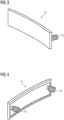
- the wear elements 12, one of which is in the Figures 3 and 4 shown, are each plate-shaped and have a ring-segment-like outer contour that follows the shape of the inner ring 2. They are made of the same material from which the inner ring 2 is also made.
- the wear elements 12 may also have a softer material than the inner ring 2.
- Each wear element 12 is detachably connected to an inner ring side wall 11.
- each wear element 12 is provided on the rear side with two welded threaded bolts 14, which extend through through holes 15 of the inner ring 2 and are secured on the rear side with a nut (not shown in detail).
- FIGS. 5 to 8 show a guide vane ring 1 according to a further embodiment of the present invention, which differs from the previously described embodiment primarily in the type of wear elements 12 used.
- each wear element 12 is used per retaining web 8, each positioned between one of the retaining web guide projections 13 and the immediately adjacent inner ring side wall 11.
- the contour of the front surface of each wear element 12 follows the contour of the facing surface of the associated retaining web guide projection 13.
- each wear element 8 is provided with a welded or otherwise fastened threaded bolt 14.
- the inner ring side walls 11 are each provided with recesses 16 that positively receive the wear elements 12 and in each of which a through hole 15 is positioned to receive a threaded bolt 14.
- the wear elements 12 compensate for the play existing between the retaining webs 8 and the immediately adjacent inner ring side walls 11 and prevent direct contact between the retaining webs 8 and the inner ring side walls 11, which can occur without such wear elements 12 due to vibrations of the individual components excited during turbine operation.
- wear is reduced by the use of wear elements 12 according to the invention.
- the wear elements 12 which can be replaced quickly, easily, and inexpensively during maintenance work, primarily wear out. Repair of the inner ring 2 in the area of the retaining webs 8 is thus completely eliminated or very minimal.
- the wear elements 12 can be provided during the new production of a guide vane ring 1. They can also be added to an existing guide vane ring 1 during maintenance or repair work.
Landscapes
- Engineering & Computer Science (AREA)
- Mechanical Engineering (AREA)
- General Engineering & Computer Science (AREA)
- Turbine Rotor Nozzle Sealing (AREA)
Claims (7)
- Couronne (1) d'aubes fixes,qui est subdivisée en une moitié supérieure et en une moitié inférieure de couronne d'aubes fixes,comprenant un anneau (2) intérieur en au moins deux parties,qui a une section transversale sensiblement en forme de U
etforme un conduit (9) d'écoulement s'étendant dans la direction du pourtour et ouvert vers l'extérieur radialement,qui est délimité par une paroi (10) de fond d'anneau intérieur et par deux parois (11) latérales d'anneau intérieur,et une pluralité de plateformes (5) d'aube, qui reçoivent des aubes (4) fixes, qui sont disposées le long du pourtour extérieur de l'anneau (2) intérieur et qui ont respectivement des entretoises (8) de maintien en saillie vers l'intérieur radialement et à distance les unes des autres dans la direction axiale,qui enveloppent de l'extérieur les parois (11) latérales de l'anneau intérieur,dans laquelledes éléments (12) d'usure sont insérés dans des intervalles présents entre des entretoises (8) de maintien et des parois (11) latérales de l'anneau intérieur immédiatement voisines,caractérisée en ce queles éléments (12) d'usure sont constitués en forme de plaque. - Couronne (1) d'aubes fixes suivant la revendication 1,
caractérisée en ce que
les éléments (12) d'usure sont dans le même matériau que celui en lequel est fabriqué l'anneau intérieur ou en un matériau plus tendre. - Couronne (1) d'aubes fixes suivant l'une des revendications précédentes,
caractérisée en ce que
chaque élément (12) d'usure est assemblé de manière amovible à une entretoise (8) de maintien ou à une paroi (11) latérale de l'anneau intérieur. - Couronne (1) d'aubes fixes suivant la revendication 3,
caractérisée en ce que
chaque élément (12) d'usure est fixé à une entretoise (8) de maintien ou à une paroi (11) latérale de l'anneau intérieur en utilisant un vissage. - Couronne (1) d'aubes fixes suivant la revendication 4,
caractérisée en ce que
chaque élément (12) d'usure a au moins un boulon (14) fileté soudé. - Couronne (1) d'aubes fixes suivant l'une des revendications 3 à 5,
caractérisée en ce que
les cavités (16) recevant les éléments (12) d'usure sont prévues sur des faces intérieures d'entretoises (8) de maintien et/ou sur la surface extérieure d'au moins une paroi (11) latérale de l'anneau intérieur. - Couronne (1) d'aubes fixes suivant l'une des revendications précédentes,
caractérisée en ce que
des éléments (12) d'usure sont insérés dans des fentes présentes entre des saillies (13) de guidage d'entretoise de maintien et des parois (11) latérales de l'anneau intérieur immédiatement voisines, les saillies (13) de guidage d'entretoise de maintien faisant chacune saillie vers l'intérieur radialement.
Applications Claiming Priority (2)
| Application Number | Priority Date | Filing Date | Title |
|---|---|---|---|
| DE102020200073.5A DE102020200073A1 (de) | 2020-01-07 | 2020-01-07 | Leitschaufelkranz |
| PCT/EP2020/084894 WO2021139939A1 (fr) | 2020-01-07 | 2020-12-07 | Anneau d'aube directrice doté d'éléments d'usure |
Publications (2)
| Publication Number | Publication Date |
|---|---|
| EP4058657A1 EP4058657A1 (fr) | 2022-09-21 |
| EP4058657B1 true EP4058657B1 (fr) | 2025-05-07 |
Family
ID=73943292
Family Applications (1)
| Application Number | Title | Priority Date | Filing Date |
|---|---|---|---|
| EP20828833.2A Active EP4058657B1 (fr) | 2020-01-07 | 2020-12-07 | Couronne d'aubes fixes avec éléments d'usure |
Country Status (7)
| Country | Link |
|---|---|
| US (1) | US11965432B2 (fr) |
| EP (1) | EP4058657B1 (fr) |
| KR (1) | KR102777086B1 (fr) |
| CN (1) | CN114945733B (fr) |
| DE (1) | DE102020200073A1 (fr) |
| PL (1) | PL4058657T3 (fr) |
| WO (1) | WO2021139939A1 (fr) |
Families Citing this family (1)
| Publication number | Priority date | Publication date | Assignee | Title |
|---|---|---|---|---|
| CN116592031B (zh) * | 2023-02-27 | 2025-09-26 | 中国航发四川燃气涡轮研究院 | 兼有防粘结、防转止退功能的高温区螺纹连接方法及组件 |
Citations (1)
| Publication number | Priority date | Publication date | Assignee | Title |
|---|---|---|---|---|
| US4384822A (en) * | 1980-01-31 | 1983-05-24 | Motoren- Und Turbinen-Union Munchen Gmbh | Turbine nozzle vane suspension for gas turbine engines |
Family Cites Families (39)
| Publication number | Priority date | Publication date | Assignee | Title |
|---|---|---|---|---|
| US3070353A (en) | 1958-12-03 | 1962-12-25 | Gen Motors Corp | Shroud assembly |
| US4126405A (en) * | 1976-12-16 | 1978-11-21 | General Electric Company | Turbine nozzle |
| US5118120A (en) * | 1989-07-10 | 1992-06-02 | General Electric Company | Leaf seals |
| GB8922339D0 (en) * | 1989-10-04 | 1989-11-22 | Rolls Royce Plc | Improvements in or relating to labyrinth seal structures |
| US5429478A (en) * | 1994-03-31 | 1995-07-04 | United Technologies Corporation | Airfoil having a seal and an integral heat shield |
| DE19507673C2 (de) | 1995-03-06 | 1997-07-03 | Mtu Muenchen Gmbh | Leitrad für Turbomaschinen |
| US5630590A (en) * | 1996-03-26 | 1997-05-20 | United Technologies Corporation | Method and apparatus for improving the airsealing effectiveness in a turbine engine |
| EP0943785A1 (fr) | 1998-03-18 | 1999-09-22 | Asea Brown Boveri AG | Fixation d'une aube à un stator |
| US6220815B1 (en) | 1999-12-17 | 2001-04-24 | General Electric Company | Inter-stage seal retainer and assembly |
| DE60307302T2 (de) | 2003-12-18 | 2007-07-19 | Techspace Aero S.A. | Befestigungsvorrichtung für Statorschaufel, sowie Leitschaufelstufe eines Verdichters mit einer solchen Vorrichtung |
| US7121785B2 (en) * | 2004-07-02 | 2006-10-17 | Siemens Power Generation, Inc. | Retraction retainer system for biased turbine engine components |
| FR2875270B1 (fr) * | 2004-09-10 | 2006-12-01 | Snecma Moteurs Sa | Retenue des clavettes de centrage des anneaux sous aubes de stator a calage variable d'un moteur a turbine a gaz |
| US7527469B2 (en) * | 2004-12-10 | 2009-05-05 | Siemens Energy, Inc. | Transition-to-turbine seal apparatus and kit for transition/turbine junction of a gas turbine engine |
| US7837435B2 (en) | 2007-05-04 | 2010-11-23 | Power System Mfg., Llc | Stator damper shim |
| US7824152B2 (en) * | 2007-05-09 | 2010-11-02 | Siemens Energy, Inc. | Multivane segment mounting arrangement for a gas turbine |
| FR2938872B1 (fr) * | 2008-11-26 | 2015-11-27 | Snecma | Dispositif anti-usure pour aubes d'un distributeur de turbine d'une turbomachine aeronautique |
| EP2194230A1 (fr) | 2008-12-05 | 2010-06-09 | Siemens Aktiengesellschaft | Agencement d'aube directrice pour une turbomachine axiale |
| CH704140A1 (de) | 2010-11-29 | 2012-05-31 | Alstom Technology Ltd | Schaufelanordnung für eine rotierende Strömungsmaschine. |
| US8894378B2 (en) * | 2011-07-26 | 2014-11-25 | General Electric Company | Systems, methods, and apparatus for sealing a bucket dovetail in a turbine |
| GB201113893D0 (en) * | 2011-08-12 | 2011-09-28 | Rolls Royce Plc | Oil mist separation in gas turbine engines |
| EP2562356A1 (fr) | 2011-08-24 | 2013-02-27 | Siemens Aktiengesellschaft | Agencement de pales |
| EP2657454B1 (fr) | 2012-04-26 | 2014-05-14 | Alstom Technology Ltd | Structure de diaphragme de turbine |
| EP2823152A1 (fr) * | 2012-05-08 | 2015-01-14 | Siemens Aktiengesellschaft | Aube mobile de turbine et section axiale de rotor pour une turbine à gaz |
| FR3001252B1 (fr) | 2013-01-23 | 2015-02-13 | Snecma | Aubage fixe de distribution de flux comprenant une plate-forme interne a renforts integres |
| EP2801702B1 (fr) | 2013-05-10 | 2020-05-06 | Safran Aero Boosters SA | Virole interne de redresseur de turbomachine avec joint abradable |
| EP2884052B1 (fr) | 2013-12-13 | 2018-02-21 | Siemens Aktiengesellschaft | Rotor pour une turbomachine avec bague d'écoulement fermée profilée et son procédé de fabrication |
| EP2966269A1 (fr) | 2014-07-08 | 2016-01-13 | MTU Aero Engines GmbH | Système de protection contre l'usure pour une turbomachine, procedé et compresseur |
| US10215192B2 (en) * | 2014-07-24 | 2019-02-26 | Siemens Aktiengesellschaft | Stator vane system usable within a gas turbine engine |
| EP3015655A1 (fr) * | 2014-10-30 | 2016-05-04 | Siemens Aktiengesellschaft | Agencement de disque de roue doté de tôles d'étanchéité |
| US9587517B2 (en) * | 2014-12-29 | 2017-03-07 | Rolls-Royce North American Technologies, Inc. | Blade track assembly with turbine tip clearance control |
| EP3075961A1 (fr) | 2015-04-02 | 2016-10-05 | Siemens Aktiengesellschaft | Ensemble d'aube directrice |
| EP3085900B1 (fr) | 2015-04-21 | 2020-08-05 | Ansaldo Energia Switzerland AG | Lèvre abradable pour une turbine à gaz |
| DE102016202519A1 (de) * | 2016-02-18 | 2017-08-24 | MTU Aero Engines AG | Leitschaufelsegment für eine Strömungsmaschine |
| US11066951B2 (en) | 2016-04-21 | 2021-07-20 | Raytheon Technologies Corporation | Wear liner for fixed stator vanes |
| GB201614711D0 (en) | 2016-08-31 | 2016-10-12 | Rolls Royce Plc | Axial flow machine |
| FR3070718B1 (fr) * | 2017-09-06 | 2019-08-23 | Safran Aircraft Engines | Ensemble de turbine a secteurs d'anneau |
| CN110030037B (zh) | 2018-01-11 | 2021-08-13 | 中国航发商用航空发动机有限责任公司 | 涡轮导向叶片、涡轮导向叶片组件以及核心机 |
| KR102142141B1 (ko) * | 2018-08-17 | 2020-08-06 | 두산중공업 주식회사 | 터빈, 가스 터빈, 및 터빈 블레이드 분리 방법 |
| US11174742B2 (en) * | 2019-07-19 | 2021-11-16 | Rolls-Royce Plc | Turbine section of a gas turbine engine with ceramic matrix composite vanes |
-
2020
- 2020-01-07 DE DE102020200073.5A patent/DE102020200073A1/de not_active Withdrawn
- 2020-12-07 US US17/788,932 patent/US11965432B2/en active Active
- 2020-12-07 WO PCT/EP2020/084894 patent/WO2021139939A1/fr not_active Ceased
- 2020-12-07 PL PL20828833.2T patent/PL4058657T3/pl unknown
- 2020-12-07 KR KR1020227026844A patent/KR102777086B1/ko active Active
- 2020-12-07 CN CN202080092166.4A patent/CN114945733B/zh active Active
- 2020-12-07 EP EP20828833.2A patent/EP4058657B1/fr active Active
Patent Citations (1)
| Publication number | Priority date | Publication date | Assignee | Title |
|---|---|---|---|---|
| US4384822A (en) * | 1980-01-31 | 1983-05-24 | Motoren- Und Turbinen-Union Munchen Gmbh | Turbine nozzle vane suspension for gas turbine engines |
Also Published As
| Publication number | Publication date |
|---|---|
| KR20220116333A (ko) | 2022-08-22 |
| US11965432B2 (en) | 2024-04-23 |
| KR102777086B1 (ko) | 2025-03-10 |
| DE102020200073A1 (de) | 2021-07-08 |
| US20230340886A1 (en) | 2023-10-26 |
| CN114945733B (zh) | 2023-10-20 |
| PL4058657T3 (pl) | 2025-09-15 |
| CN114945733A (zh) | 2022-08-26 |
| WO2021139939A1 (fr) | 2021-07-15 |
| EP4058657A1 (fr) | 2022-09-21 |
Similar Documents
| Publication | Publication Date | Title |
|---|---|---|
| EP2132414B1 (fr) | Agencement en feuillure | |
| EP1944472A1 (fr) | Partie axiale d'un rotor de turbine, élément d'étanchéité pour un rotor équipé d'aubes de rotor d'une turbine et rotor de turbine | |
| EP1199440B1 (fr) | Segments d'anneau statorique à connection par bride | |
| CH700001A1 (de) | Laufschaufelanordnung, insbesondere für eine gasturbine. | |
| EP1898054B1 (fr) | Turbine a gaz | |
| DE2952023A1 (de) | Schaufelhaltevorrichtung | |
| EP2129871A1 (fr) | Agencement pour fixation axiale à des ailettes de rotor et turbine à gaz dotée d'un tel agencement | |
| EP2823152A1 (fr) | Aube mobile de turbine et section axiale de rotor pour une turbine à gaz | |
| EP3574188B1 (fr) | Procédé permettant de fermer de manière étanche un interstice annulaire dans une turbine ainsi que turbine | |
| EP1766192B1 (fr) | Roue a aubes d'une turbine presentant une aube et au moins un canal refrigerant | |
| EP2716874B1 (fr) | Stator, procédé de montage et turbomachine | |
| EP1413715A1 (fr) | Dispositif de refroidissement pour une plate-forme d'une aube d'une turbine à gaz | |
| EP4058657B1 (fr) | Couronne d'aubes fixes avec éléments d'usure | |
| WO1996013668A1 (fr) | Compresseur radial ou turbine radiale avec un diffuseur ou une couronne directrice de turbine a aubes directrices | |
| EP2394028B1 (fr) | Dispositif d'étanchéité sur l'arbre à aubes d'un étage de rotor d'une turbomachine axiale et son utilisation | |
| EP2994615B1 (fr) | Rotor pour une turbomachine thermique | |
| EP2811118A1 (fr) | Segment d'aube directrice d'une turbomachine et turbine | |
| DE2158578A1 (de) | Stator-Schaufelkonstruktion | |
| WO2015007494A1 (fr) | Rotor pour une turbomachine thermique | |
| EP3628030B1 (fr) | Méthode de maintenance d'une turbomachine | |
| EP4134488B1 (fr) | Roue de fraise | |
| DE102015122874B4 (de) | Austenitisches Dampfturbinenringsegment für eine Dampfturbinenleiteinrichtung und Dampfturbinenleiteinrichtung | |
| EP2860352A1 (fr) | Rotor, procédé de manufacture et aube associés | |
| EP3885535B1 (fr) | Bague d'étanchéité pour un rotor et rotor doté d'une telle bague d'étanchéité | |
| CH705377A1 (de) | Verfahren zur Rekonditionierung eines Rotors einer Strömungsmaschine. |
Legal Events
| Date | Code | Title | Description |
|---|---|---|---|
| STAA | Information on the status of an ep patent application or granted ep patent |
Free format text: STATUS: UNKNOWN |
|
| STAA | Information on the status of an ep patent application or granted ep patent |
Free format text: STATUS: THE INTERNATIONAL PUBLICATION HAS BEEN MADE |
|
| PUAI | Public reference made under article 153(3) epc to a published international application that has entered the european phase |
Free format text: ORIGINAL CODE: 0009012 |
|
| STAA | Information on the status of an ep patent application or granted ep patent |
Free format text: STATUS: REQUEST FOR EXAMINATION WAS MADE |
|
| 17P | Request for examination filed |
Effective date: 20220616 |
|
| AK | Designated contracting states |
Kind code of ref document: A1 Designated state(s): AL AT BE BG CH CY CZ DE DK EE ES FI FR GB GR HR HU IE IS IT LI LT LU LV MC MK MT NL NO PL PT RO RS SE SI SK SM TR |
|
| DAV | Request for validation of the european patent (deleted) | ||
| DAX | Request for extension of the european patent (deleted) | ||
| GRAP | Despatch of communication of intention to grant a patent |
Free format text: ORIGINAL CODE: EPIDOSNIGR1 |
|
| STAA | Information on the status of an ep patent application or granted ep patent |
Free format text: STATUS: GRANT OF PATENT IS INTENDED |
|
| INTG | Intention to grant announced |
Effective date: 20250102 |
|
| GRAS | Grant fee paid |
Free format text: ORIGINAL CODE: EPIDOSNIGR3 |
|
| GRAA | (expected) grant |
Free format text: ORIGINAL CODE: 0009210 |
|
| STAA | Information on the status of an ep patent application or granted ep patent |
Free format text: STATUS: THE PATENT HAS BEEN GRANTED |
|
| AK | Designated contracting states |
Kind code of ref document: B1 Designated state(s): AL AT BE BG CH CY CZ DE DK EE ES FI FR GB GR HR HU IE IS IT LI LT LU LV MC MK MT NL NO PL PT RO RS SE SI SK SM TR |
|
| REG | Reference to a national code |
Ref country code: GB Ref legal event code: FG4D Free format text: NOT ENGLISH |
|
| REG | Reference to a national code |
Ref country code: CH Ref legal event code: EP |
|
| REG | Reference to a national code |
Ref country code: DE Ref legal event code: R096 Ref document number: 502020011037 Country of ref document: DE |
|
| REG | Reference to a national code |
Ref country code: IE Ref legal event code: FG4D Free format text: LANGUAGE OF EP DOCUMENT: GERMAN |
|
| REG | Reference to a national code |
Ref country code: NL Ref legal event code: FP |
|
| PG25 | Lapsed in a contracting state [announced via postgrant information from national office to epo] |
Ref country code: ES Free format text: LAPSE BECAUSE OF FAILURE TO SUBMIT A TRANSLATION OF THE DESCRIPTION OR TO PAY THE FEE WITHIN THE PRESCRIBED TIME-LIMIT Effective date: 20250507 Ref country code: PT Free format text: LAPSE BECAUSE OF FAILURE TO SUBMIT A TRANSLATION OF THE DESCRIPTION OR TO PAY THE FEE WITHIN THE PRESCRIBED TIME-LIMIT Effective date: 20250908 Ref country code: FI Free format text: LAPSE BECAUSE OF FAILURE TO SUBMIT A TRANSLATION OF THE DESCRIPTION OR TO PAY THE FEE WITHIN THE PRESCRIBED TIME-LIMIT Effective date: 20250507 |
|
| REG | Reference to a national code |
Ref country code: LT Ref legal event code: MG9D |
|
| PG25 | Lapsed in a contracting state [announced via postgrant information from national office to epo] |
Ref country code: NO Free format text: LAPSE BECAUSE OF FAILURE TO SUBMIT A TRANSLATION OF THE DESCRIPTION OR TO PAY THE FEE WITHIN THE PRESCRIBED TIME-LIMIT Effective date: 20250807 Ref country code: GR Free format text: LAPSE BECAUSE OF FAILURE TO SUBMIT A TRANSLATION OF THE DESCRIPTION OR TO PAY THE FEE WITHIN THE PRESCRIBED TIME-LIMIT Effective date: 20250808 |
|
| PG25 | Lapsed in a contracting state [announced via postgrant information from national office to epo] |
Ref country code: BG Free format text: LAPSE BECAUSE OF FAILURE TO SUBMIT A TRANSLATION OF THE DESCRIPTION OR TO PAY THE FEE WITHIN THE PRESCRIBED TIME-LIMIT Effective date: 20250507 |
|
| PG25 | Lapsed in a contracting state [announced via postgrant information from national office to epo] |
Ref country code: HR Free format text: LAPSE BECAUSE OF FAILURE TO SUBMIT A TRANSLATION OF THE DESCRIPTION OR TO PAY THE FEE WITHIN THE PRESCRIBED TIME-LIMIT Effective date: 20250507 |
|
| PG25 | Lapsed in a contracting state [announced via postgrant information from national office to epo] |
Ref country code: RS Free format text: LAPSE BECAUSE OF FAILURE TO SUBMIT A TRANSLATION OF THE DESCRIPTION OR TO PAY THE FEE WITHIN THE PRESCRIBED TIME-LIMIT Effective date: 20250807 |
|
| PG25 | Lapsed in a contracting state [announced via postgrant information from national office to epo] |
Ref country code: IS Free format text: LAPSE BECAUSE OF FAILURE TO SUBMIT A TRANSLATION OF THE DESCRIPTION OR TO PAY THE FEE WITHIN THE PRESCRIBED TIME-LIMIT Effective date: 20250907 |
|
| PG25 | Lapsed in a contracting state [announced via postgrant information from national office to epo] |
Ref country code: LV Free format text: LAPSE BECAUSE OF FAILURE TO SUBMIT A TRANSLATION OF THE DESCRIPTION OR TO PAY THE FEE WITHIN THE PRESCRIBED TIME-LIMIT Effective date: 20250507 |
|
| PGFP | Annual fee paid to national office [announced via postgrant information from national office to epo] |
Ref country code: GB Payment date: 20251223 Year of fee payment: 6 |
|
| PG25 | Lapsed in a contracting state [announced via postgrant information from national office to epo] |
Ref country code: DK Free format text: LAPSE BECAUSE OF FAILURE TO SUBMIT A TRANSLATION OF THE DESCRIPTION OR TO PAY THE FEE WITHIN THE PRESCRIBED TIME-LIMIT Effective date: 20250507 Ref country code: SM Free format text: LAPSE BECAUSE OF FAILURE TO SUBMIT A TRANSLATION OF THE DESCRIPTION OR TO PAY THE FEE WITHIN THE PRESCRIBED TIME-LIMIT Effective date: 20250507 |
|
| PGFP | Annual fee paid to national office [announced via postgrant information from national office to epo] |
Ref country code: IT Payment date: 20251218 Year of fee payment: 6 |
|
| PGFP | Annual fee paid to national office [announced via postgrant information from national office to epo] |
Ref country code: FR Payment date: 20251223 Year of fee payment: 6 Ref country code: NL Payment date: 20251222 Year of fee payment: 6 |
|
| PGFP | Annual fee paid to national office [announced via postgrant information from national office to epo] |
Ref country code: TR Payment date: 20251118 Year of fee payment: 6 |
|
| PG25 | Lapsed in a contracting state [announced via postgrant information from national office to epo] |
Ref country code: CZ Free format text: LAPSE BECAUSE OF FAILURE TO SUBMIT A TRANSLATION OF THE DESCRIPTION OR TO PAY THE FEE WITHIN THE PRESCRIBED TIME-LIMIT Effective date: 20250507 |
|
| PGFP | Annual fee paid to national office [announced via postgrant information from national office to epo] |
Ref country code: PL Payment date: 20251114 Year of fee payment: 6 |
|
| PG25 | Lapsed in a contracting state [announced via postgrant information from national office to epo] |
Ref country code: EE Free format text: LAPSE BECAUSE OF FAILURE TO SUBMIT A TRANSLATION OF THE DESCRIPTION OR TO PAY THE FEE WITHIN THE PRESCRIBED TIME-LIMIT Effective date: 20250507 |
|
| PG25 | Lapsed in a contracting state [announced via postgrant information from national office to epo] |
Ref country code: SK Free format text: LAPSE BECAUSE OF FAILURE TO SUBMIT A TRANSLATION OF THE DESCRIPTION OR TO PAY THE FEE WITHIN THE PRESCRIBED TIME-LIMIT Effective date: 20250507 |
|
| PG25 | Lapsed in a contracting state [announced via postgrant information from national office to epo] |
Ref country code: RO Free format text: LAPSE BECAUSE OF FAILURE TO SUBMIT A TRANSLATION OF THE DESCRIPTION OR TO PAY THE FEE WITHIN THE PRESCRIBED TIME-LIMIT Effective date: 20250507 |
|
| REG | Reference to a national code |
Ref country code: DE Ref legal event code: R097 Ref document number: 502020011037 Country of ref document: DE |
|
| PLBE | No opposition filed within time limit |
Free format text: ORIGINAL CODE: 0009261 |
|
| STAA | Information on the status of an ep patent application or granted ep patent |
Free format text: STATUS: NO OPPOSITION FILED WITHIN TIME LIMIT |
|
| REG | Reference to a national code |
Ref country code: CH Ref legal event code: L10 Free format text: ST27 STATUS EVENT CODE: U-0-0-L10-L00 (AS PROVIDED BY THE NATIONAL OFFICE) Effective date: 20260318 |
|
| PGFP | Annual fee paid to national office [announced via postgrant information from national office to epo] |
Ref country code: DE Payment date: 20251229 Year of fee payment: 6 |
|
| 26N | No opposition filed |
Effective date: 20260210 |