EP4059592A1 - Éprouvette, ainsi que dispositif et procédé de dispersion et d'homogénéisation - Google Patents
Éprouvette, ainsi que dispositif et procédé de dispersion et d'homogénéisation Download PDFInfo
- Publication number
- EP4059592A1 EP4059592A1 EP21162916.7A EP21162916A EP4059592A1 EP 4059592 A1 EP4059592 A1 EP 4059592A1 EP 21162916 A EP21162916 A EP 21162916A EP 4059592 A1 EP4059592 A1 EP 4059592A1
- Authority
- EP
- European Patent Office
- Prior art keywords
- sample
- sample tube
- weight element
- closure
- receiving space
- Prior art date
- Legal status (The legal status is an assumption and is not a legal conclusion. Google has not performed a legal analysis and makes no representation as to the accuracy of the status listed.)
- Granted
Links
Images

Classifications
-
- G—PHYSICS
- G01—MEASURING; TESTING
- G01N—INVESTIGATING OR ANALYSING MATERIALS BY DETERMINING THEIR CHEMICAL OR PHYSICAL PROPERTIES
- G01N1/00—Sampling; Preparing specimens for investigation
- G01N1/28—Preparing specimens for investigation including physical details of (bio-)chemical methods covered elsewhere, e.g. G01N33/50, C12Q
- G01N1/286—Preparing specimens for investigation including physical details of (bio-)chemical methods covered elsewhere, e.g. G01N33/50, C12Q involving mechanical work, e.g. chopping, disintegrating, compacting, homogenising
-
- B—PERFORMING OPERATIONS; TRANSPORTING
- B01—PHYSICAL OR CHEMICAL PROCESSES OR APPARATUS IN GENERAL
- B01F—MIXING, e.g. DISSOLVING, EMULSIFYING OR DISPERSING
- B01F23/00—Mixing according to the phases to be mixed, e.g. dispersing or emulsifying
- B01F23/50—Mixing liquids with solids
- B01F23/51—Methods thereof
-
- B—PERFORMING OPERATIONS; TRANSPORTING
- B01—PHYSICAL OR CHEMICAL PROCESSES OR APPARATUS IN GENERAL
- B01F—MIXING, e.g. DISSOLVING, EMULSIFYING OR DISPERSING
- B01F23/00—Mixing according to the phases to be mixed, e.g. dispersing or emulsifying
- B01F23/50—Mixing liquids with solids
- B01F23/53—Mixing liquids with solids using driven stirrers
-
- B—PERFORMING OPERATIONS; TRANSPORTING
- B01—PHYSICAL OR CHEMICAL PROCESSES OR APPARATUS IN GENERAL
- B01F—MIXING, e.g. DISSOLVING, EMULSIFYING OR DISPERSING
- B01F29/00—Mixers with rotating receptacles
- B01F29/30—Mixing the contents of individual packages or containers, e.g. by rotating tins or bottles
-
- B—PERFORMING OPERATIONS; TRANSPORTING
- B01—PHYSICAL OR CHEMICAL PROCESSES OR APPARATUS IN GENERAL
- B01F—MIXING, e.g. DISSOLVING, EMULSIFYING OR DISPERSING
- B01F29/00—Mixers with rotating receptacles
- B01F29/80—Mixers with rotating receptacles rotating about a substantially vertical axis
- B01F29/87—Mixers with rotating receptacles rotating about a substantially vertical axis with rotary cylinders
-
- B—PERFORMING OPERATIONS; TRANSPORTING
- B01—PHYSICAL OR CHEMICAL PROCESSES OR APPARATUS IN GENERAL
- B01F—MIXING, e.g. DISSOLVING, EMULSIFYING OR DISPERSING
- B01F31/00—Mixers with shaking, oscillating, or vibrating mechanisms
- B01F31/10—Mixers with shaking, oscillating, or vibrating mechanisms with a mixing receptacle rotating alternately in opposite directions
-
- B—PERFORMING OPERATIONS; TRANSPORTING
- B01—PHYSICAL OR CHEMICAL PROCESSES OR APPARATUS IN GENERAL
- B01F—MIXING, e.g. DISSOLVING, EMULSIFYING OR DISPERSING
- B01F31/00—Mixers with shaking, oscillating, or vibrating mechanisms
- B01F31/20—Mixing the contents of independent containers, e.g. test tubes
-
- B—PERFORMING OPERATIONS; TRANSPORTING
- B01—PHYSICAL OR CHEMICAL PROCESSES OR APPARATUS IN GENERAL
- B01F—MIXING, e.g. DISSOLVING, EMULSIFYING OR DISPERSING
- B01F33/00—Other mixers; Mixing plants; Combinations of mixers
- B01F33/25—Mixers with loose mixing elements, e.g. loose balls in a receptacle
- B01F33/253—Mixers with loose mixing elements, e.g. loose balls in a receptacle using sliders or cylindrical elements as loose mixing element
-
- B—PERFORMING OPERATIONS; TRANSPORTING
- B01—PHYSICAL OR CHEMICAL PROCESSES OR APPARATUS IN GENERAL
- B01F—MIXING, e.g. DISSOLVING, EMULSIFYING OR DISPERSING
- B01F33/00—Other mixers; Mixing plants; Combinations of mixers
- B01F33/35—Mixing after turning the mixing vessel upside down
-
- B—PERFORMING OPERATIONS; TRANSPORTING
- B01—PHYSICAL OR CHEMICAL PROCESSES OR APPARATUS IN GENERAL
- B01L—CHEMICAL OR PHYSICAL LABORATORY APPARATUS FOR GENERAL USE
- B01L3/00—Containers or dishes for laboratory use, e.g. laboratory glassware; Droppers
- B01L3/50—Containers for the purpose of retaining a material to be analysed, e.g. test tubes
- B01L3/502—Containers for the purpose of retaining a material to be analysed, e.g. test tubes with fluid transport, e.g. in multi-compartment structures
-
- B—PERFORMING OPERATIONS; TRANSPORTING
- B01—PHYSICAL OR CHEMICAL PROCESSES OR APPARATUS IN GENERAL
- B01L—CHEMICAL OR PHYSICAL LABORATORY APPARATUS FOR GENERAL USE
- B01L3/00—Containers or dishes for laboratory use, e.g. laboratory glassware; Droppers
- B01L3/50—Containers for the purpose of retaining a material to be analysed, e.g. test tubes
- B01L3/508—Rigid containers without fluid transport within
- B01L3/5082—Test tubes per se
- B01L3/50825—Closing or opening means, corks, bungs
-
- B—PERFORMING OPERATIONS; TRANSPORTING
- B02—CRUSHING, PULVERISING, OR DISINTEGRATING; PREPARATORY TREATMENT OF GRAIN FOR MILLING
- B02C—CRUSHING, PULVERISING, OR DISINTEGRATING IN GENERAL; MILLING GRAIN
- B02C19/00—Other disintegrating devices or methods
- B02C19/20—Disintegrating by grating
-
- G—PHYSICS
- G01—MEASURING; TESTING
- G01N—INVESTIGATING OR ANALYSING MATERIALS BY DETERMINING THEIR CHEMICAL OR PHYSICAL PROPERTIES
- G01N1/00—Sampling; Preparing specimens for investigation
- G01N1/28—Preparing specimens for investigation including physical details of (bio-)chemical methods covered elsewhere, e.g. G01N33/50, C12Q
- G01N1/38—Diluting, dispersing or mixing samples
-
- B—PERFORMING OPERATIONS; TRANSPORTING
- B01—PHYSICAL OR CHEMICAL PROCESSES OR APPARATUS IN GENERAL
- B01F—MIXING, e.g. DISSOLVING, EMULSIFYING OR DISPERSING
- B01F2101/00—Mixing characterised by the nature of the mixed materials or by the application field
- B01F2101/23—Mixing of laboratory samples e.g. in preparation of analysing or testing properties of materials
-
- B—PERFORMING OPERATIONS; TRANSPORTING
- B01—PHYSICAL OR CHEMICAL PROCESSES OR APPARATUS IN GENERAL
- B01L—CHEMICAL OR PHYSICAL LABORATORY APPARATUS FOR GENERAL USE
- B01L2300/00—Additional constructional details
- B01L2300/04—Closures and closing means
- B01L2300/041—Connecting closures to device or container
- B01L2300/042—Caps; Plugs
-
- B—PERFORMING OPERATIONS; TRANSPORTING
- B01—PHYSICAL OR CHEMICAL PROCESSES OR APPARATUS IN GENERAL
- B01L—CHEMICAL OR PHYSICAL LABORATORY APPARATUS FOR GENERAL USE
- B01L2300/00—Additional constructional details
- B01L2300/04—Closures and closing means
- B01L2300/046—Function or devices integrated in the closure
-
- G—PHYSICS
- G01—MEASURING; TESTING
- G01N—INVESTIGATING OR ANALYSING MATERIALS BY DETERMINING THEIR CHEMICAL OR PHYSICAL PROPERTIES
- G01N1/00—Sampling; Preparing specimens for investigation
- G01N1/28—Preparing specimens for investigation including physical details of (bio-)chemical methods covered elsewhere, e.g. G01N33/50, C12Q
- G01N1/286—Preparing specimens for investigation including physical details of (bio-)chemical methods covered elsewhere, e.g. G01N33/50, C12Q involving mechanical work, e.g. chopping, disintegrating, compacting, homogenising
- G01N2001/2866—Grinding or homogeneising
Definitions
- the invention relates to a sample tube and a device and a method for dispersing and homogenizing a sample, in particular a sample located in the sample tube.
- sample tubes and devices and methods for dispersing and homogenizing samples are known in the prior art.
- homogenizers are used to disrupt cells.
- the samples to be digested are usually transferred to test tubes or sample tubes.
- the cells can be disrupted by applying mechanical energy, with the cell walls usually being destroyed by shear forces.
- a piston is moved back and forth at a short distance from the wall of the sample vessel.
- cells can also be disrupted by adding grinding media, for example glass beads, and shaking the sample on a shaker.
- mechanical energy can also be introduced into sample liquids by ultrasound in order to disrupt cells. Another way of cell disruption is to force a sample liquid through a narrow valve under high pressure (French press).
- the CH 710 352 discloses, for example, a disposable container for mixing, homogenizing, extracting, fractionating or suspending sample material with a cylindrical tube and a cover which has a lid, a spiral cylinder and a plunger. Both the bottom of the tube and the plunger have radially arranged friction ribs. By means of a drive, the plunger can be moved in the vertical direction within the tube and rotated in order to homogenize the sample material.
- the U.S. 8,162,247 (Biomedical Polymers Inc.) describes a modular mortar system for comminuting samples.
- the mortar system includes a tube having a bottom surface that has a first grinding surface and a peripheral wall that forms a sample receiving space.
- a modular mortar attachment has an actuating shaft on which, at a distal end, there is a socket for different mortar heads, each of which has a second grinding surface, and at its proximal end, a holding device.
- the actuating shaft is guided through a screw cap with which the tube can be closed.
- the U.S. 4,715,545 (Sage Products Inc.) relates to a system for mincing tissue samples or the like while protecting both the samples and an operator of the system from contamination.
- a sample can be introduced into the system and transported in it as well as crushed.
- the system comprises a tube with a closed bottom surface designed as a grinding surface and a mortar device that can be inserted into the tube.
- the tube can be closed with a screw cap. Before crushing, the screw cap is removed and the mortar device is inserted into the tube. To reduce the risk of contamination, the mortar device has a protective cover that can be placed over the tube.
- a disadvantage of most methods, however, is that insufficient cleaning of the devices used for this can lead to carryover and contamination. It is therefore an advantage if disposable means can be used for cell disruption or for homogenization and dispersing.
- the object of the invention is to create a sample tube belonging to the technical field mentioned at the outset, which enables a self-contained system for dispersing and homogenizing samples without the risk of contamination or carryover. Furthermore, the object of the invention is to create a corresponding method for dispersing or homogenizing a sample.
- the sample tube has a cylindrical wall and a first end and a second end.
- the first end of the sample tube is closed by a bottom surface, so that a receiving space with a longitudinal axis for a sample is formed between the bottom surface and the cylindrical wall.
- the second end has a latch releasably connected thereto.
- a weight element is accommodated within the accommodation space, which is shaped and dimensioned in such a way that the weight element can rotate freely in the accommodation space only about the longitudinal axis of the latter.
- the sample is introduced into the receiving space so that it is located between the weight element and the second or first end.
- the closure is then connected to the second end and the sample tube is rotated in such a way that the sample is below the weight element in the direction of gravity.
- the sample tube is rotated around the longitudinal axis of the receiving space.
- the weight element Due to its moment of inertia, the weight element is set in rotation relative to the receiving space and to a sample located in the receiving space with a time delay. Due to the resulting difference in speed, shearing forces act on the sample, which is arranged between the bottom surface or the closure and the weight element, which disperse or homogenize the sample.
- the sample tube has all the elements to disperse or homogenize a sample liquid, so that by using the inventive Sample tubes carryover or contamination of the sample liquid is prevented.
- the time required to carry out the dispersion or homogenization can also be significantly reduced, since only the sample has to be filled into the sample tube and the preparation or cleaning of additional equipment is no longer necessary.
- a sample located in the receiving space is also set in rotary motion due to the friction with the closure or the cylindrical wall when the sample tube rotates, but with a time delay relative to this due to inertia. Due to the friction between the sample and the weight element, the weight element is finally set in rotation, but also with a time delay compared to the sample. This time delay causes the sample tube, the sample and the weight element to rotate at different speeds. As a result, a force is applied to the sample, particularly in the form of shear forces.
- the cylindrical wall of the sample tube is preferably made of a polymer material, in particular polypropylene, polystyrene or polyethylene terephthalate.
- the wall of the sample tube can also be made of glass.
- the bottom surface of the sample tube is preferably flat. Alternatively, however, the bottom surface can also be convexly arched or designed in the shape of a cone.
- the bottom surface is preferably designed in one piece with the cylindrical wall and more preferably consists of the same material.
- the cylindrical wall is preferably transparent.
- the cylindrical wall can also be opaque, for example for dispersing or homogenizing samples which contain light-sensitive substances.
- the cylindrical wall can only be opaque to light of a specific spectrum, for example UV light.
- the cylindrical wall preferably has a graduation or scaling, which enables the filling level of the sample tube to be read off.
- the cylindrical wall can have a writing surface on its outside, with which the sample tube can be written.
- the receiving space defines a volume for receiving a sample, in particular a sample liquid.
- the volume of the receiving space is preferably from 100 ⁇ l to 500 ml, in particular from 1 ml to 100 ml.
- specific embodiments of the sample tube can also have receiving spaces with a smaller or larger volume.
- the diameter of the cylindrical wall is preferably from 5 mm to 50 mm.
- the length of the sample tube ie its maximum extent along the longitudinal axis, is preferably from 10 mm to 250 mm without a closure.
- the sample tube can be in the form of a microreaction vessel or a centrifuge tube.
- the closure is preferably a screw or snap cap.
- the closure can also be designed in the form of a stopper, in particular made of polyethylene.
- the closure is preferably made of the same material as the cylindrical wall.
- the closure can also consist of a different material, in particular of a different polymer.
- the receiving space can preferably be closed in a liquid-tight manner at the second end with the closure.
- the closure is releasably connected to the second end of the cylindrical wall, which means that the closure can be removed from or with the second end without the use of tools or damage.
- the closure is connected to the cylindrical wall via a strap or similar, so that it cannot be lost in the released state.
- the weight element preferably has a mass that is large enough to generate sufficiently large shearing forces when it moves relative to the cylindrical wall to enable dispersion or homogenization, in particular cell disruption, of a sample located in the receiving space.
- the mass of the weight element is preferably from 5 g to 500 g.
- the weight element preferably has a round cross-section, which has a slightly smaller diameter than the diameter of the receiving space, so that it moves around the receiving space with as little friction as possible longitudinal axis can rotate.
- the difference in diameter is preferably less than 1 mm, in particular less than 0.5 mm, so that only as little liquid as possible can penetrate between the weight element and the cylindrical wall when a liquid is received in the receiving space.
- the weight element is shaped in such a way that it can only rotate about the longitudinal axis of the receiving space. This ensures that a particularly efficient dispersion and homogenization of a sample located in the receiving space is made possible.
- the weight element can consist of the same material as the cylindrical wall. However, the weight element preferably consists of a different material, in particular glass, ceramic, metal or an alloy.
- sample tubes are preferably manufactured in such a way or treated after their manufacture in such a way that they are sterile and in particular free of pyrogens, human DNA, RNase and/or DNase.
- the materials constituting the cylindrical wall, base, closure and weight member are preferably non-cytotoxic.
- the weight element is preferably located initially on the floor surface, so that when a sample is taken up into the receiving space, it is located between the weight element and the closure. In this case, before dispersing or homogenizing, the sample tube is turned over so that the cap is pointing downwards. As a result, the weight element presses on the sample with its mass.
- the sample tube preferably contains a liquid, in particular water or a buffer solution, which is arranged in particular between the weight element and the second end.
- the liquid is particularly preferably sterile.
- the sample is preferably in solid form. Alternatively, however, the sample can also be in the form of a sample liquid. If the sample is a sample liquid, cells are preferably suspended in the sample liquid. It can be are preferably human, animal, insect, plant or fungal cells, as well as bacteria, archaea, protozoa, yeasts or chimeras. If the sample is a solid sample, the sample is preferably a piece of tissue, in particular human or animal tissue, eg from a biopsy. Alternatively, however, a solid sample can also be a mineral, soil, a part of a plant or a foodstuff, for example a meat sample. A solid sample is preferably introduced into the receiving space together with water or a buffer solution.
- the device preferably has a cover surrounding the at least one receptacle. This cover prevents contamination of the ambient air by aerosols.
- the cover preferably has a flap or door via which the at least one receptacle is accessible to a user of the device.
- the device preferably has a safety device which stops a rotary movement of the at least one receptacle when the flap or door is opened.
- the fuse can be designed electronically or mechanically.
- the rotation of the sample tube is preferably an oscillating rotary motion. This means that the direction of rotation of the sample tube changes periodically.
- the oscillating rotary movement repeatedly accelerates and decelerates the sample tube, with the weight element following these movements with a time delay due to its moment of inertia.
- the direction of rotation of the weight element and sample tube can temporarily be in opposite directions, which means that mechanical energy in the form of shearing forces is particularly high on the sample.
- the sample tube can also be rotated intermittently. This means that the sample tube always rotates in the same direction, but with periodic acceleration and deceleration phases. Due to the moment of inertia, the weight element will always rotate at a different speed than the sample tube, which means that the input of mechanical energy or shear forces on the sample can be increased.
- the closure preferably has a first friction surface on a surface facing the receiving space when the closure is connected to the second end.
- the input of mechanical energy onto the sample can be additionally increased by the first friction surface.
- the friction surface preferably has a surface structure which increases its static friction.
- the friction surface preferably has an increased roughness.
- the weight member is preferably in the form of a cylinder having a smaller cross section than the cross section of the accommodating space.
- the design of the weight element as a cylinder enables the simplest possible design of the same.
- the cylinder preferably has a thickness that is significantly smaller than the extent of the receiving space along the longitudinal axis. The thickness of the cylinder is preferably from 2mm to 40mm.
- the weight member has a second friction surface on at least one surface facing the first or second end.
- the application of mechanical energy to the sample can be additionally increased by the at least one second friction surface.
- the weight element is a cylinder
- the second friction surface is arranged on at least one of the base surfaces of the cylinder, but particularly preferably on both base surfaces.
- the first friction surface and possibly the second friction surface on the at least one surface of the weight element preferably has structural elements, in particular teeth, pyramids or grooves. Structural elements of this type allow the energy input to the sample and in particular the generation of shear forces to be increased.
- the structural elements are preferably arranged in a regular pattern on the first friction surface and possibly on the second friction surface.
- the size, arrangement and geometry of the structural elements are preferably adapted to the sample to be dispersed or homogenized. This means that, depending on the type of sample, a different sample tube is provided which has appropriate structural elements that enable optimum dispersion or homogenization of the sample.
- the weight element is preferably made of glass, stainless steel, ceramics or a plastic. Weight elements made of these materials can be produced in large numbers with relatively little effort and at low cost.
- glass, stainless steel and ceramics in particular have a high intrinsic weight, as a result of which the mass of the weight element is particularly high, which leads to a particularly good energy input to the sample.
- the present application also relates to a device for dispersing or homogenizing a sample.
- the device comprises at least one holder for a sample tube according to the above description, which can be set in rotary motion by means of a drive of the device.
- the rotary motion is preferably an oscillating or intermittent rotary motion.
- the at least one receptacle preferably has fastening means in order to be able to detachably fasten a sample tube thereon.
- the fastening means are preferably in the form of form-fitting means which are shaped to complement the bottom surface or the closure of the sample tube, so that a sample tube can be connected to the at least one receptacle in a simple and reliable manner.
- the form-fitting means can be designed, for example, as a snap closure or screw closure.
- the at least one receptacle can also have other fastening means with which a sample tube can be releasably connected to the receptacle by means of a force fit, for example by means of magnets.
- the device has at least one receptacle, but preferably more than one receptacle, for example two, three, four, five, six or more receptacles for a sample tube.
- the drive for the at least one receptacle is preferably an electric motor, in particular a servo motor or a stepping motor. This gives the drive a high level of dynamics, so that rapid changes in speed or direction of rotation and high acceleration are possible even with intermittent and oscillating rotary movements.
- the axis of rotation of the at least one recording is preferably formed by the axis of the motor, so that the receptacle is driven directly by the electric motor.
- the electric motor can act on the axis of rotation of the at least one receptacle via a gear, in particular via a worm gear or spur gear.
- each of the receptacles can preferably be set in rotary motion about its own axis of rotation by the drive.
- the device preferably has its own drive for each of the receptacles.
- all receptacles of the device can also be set in rotary motion via a gear with a single drive. It is also conceivable that the entire number of receptacles of the device are divided into groups, with all receptacles in each group being set in rotary motion by a common drive and a corresponding gear.
- the device preferably has a controller with which the drive of the at least one receptacle can be controlled.
- the device preferably has input means, for example a button, with which a user of the device in particular can start the rotary movement.
- the input means and possibly the control can be designed in such a way that a user can set the type of rotary movement and parameters of the same, such as its duration, acceleration, etc.
- the device preferably has display means, such as a liquid crystal display, for example, in order to be able to display data to a user of the device, for example parameters of the rotary movement, the duration of the rotary movement that has already elapsed or the status of the device.
- the device also has a connection with which the device can be connected to a power supply.
- the rotary movement is preferably centric. This means that the center of the recording is on its axis of rotation. Alternatively, however, the rotational movement can be eccentric. This means that the at least one receptacle is mounted in such a way that it rotates eccentrically. Due to the eccentric rotary movement, additional shearing forces can be exerted on the sample, which can further increase the efficiency of the dispersion or homogenization.
- the present application also relates to a combination of a device according to the above description with at least one sample tube according to the invention.
- the 1 1 shows an embodiment of a sample tube 1 according to the invention.
- the sample tube 1 has a cylindrical wall 2 .
- a first end of the sample tube 1 is closed with a bottom surface 3 .
- the cylindrical wall 2 and the bottom surface 3 define a receiving space 4 into which a sample can be received.
- the sample tube has a closure 5, which is a screw-on cap in the exemplary embodiment shown.
- a weight element 7 is accommodated within the accommodation space 4 .
- the weight element 7 has a shape and size that allows it to rotate about the longitudinal axis A of the receiving space 4, but essentially no further rotations about other axes. In the embodiment shown, the weight member 7 has a cylindrical shape.
- the sample tube has a sterile liquid 18 which is located between the weight element 7 and the second end of the sample tube.
- the 1 shows the sample tube in a state in which it is standing with its bottom surface 3 perpendicular to a surface, that is to say that the longitudinal axis A is parallel to the effective direction of gravity.
- the weight element therefore rests on the floor surface 3 accordingly.
- the weight element 7 has a second friction surface 8 on one of its bases.
- the 2 shows the closure 5 in the form of the screwable cover 1 from underneath.
- the closure 5 has a first friction surface 6 on its side pointing towards the receiving space 4 in the closed state.
- Both the first friction surface 6 of the closure and the second friction surface 8 of the weight element 7 have structural elements which increase the roughness of the first and second friction surface 6, 8, respectively.
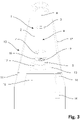
- the 3 shows a schematic representation of a device 10 according to the invention for dispersing or homogenizing a sample in combination with the sample tube 1 according to FIG 1 and 2 .
- the device 10 has a housing 11 on which a receptacle 12 for the sample tube 1 is arranged.
- the receptacle 12 is designed in such a way that the closure 5 of the sample tube is partially inserted into it and connected to it via a positive fit.
- the receptacle 12 is rotated by a drive 13 of the device 10, which is located in the housing 11 and is therefore only indicated by dashed lines.
- the rotary movement of the receptacle 12 also causes the sample tube 1 connected to it to rotate in the same manner about the longitudinal axis A of the receptacle space.
- a sample 9 is accommodated in the accommodation space 4 .
- the sample 9 is a solid sample which is in the liquid 18 of the sample tube 1 . After inserting the sample 9 into the receiving space, this will Rotated sample tube 1 so that it can be attached to the receptacle 12. As a result, the sample 9 slips or flows due to gravity onto the side of the closure 5 facing the receiving space 4. The weight element 7 will also slide due to the gravity along the longitudinal axis A in the receiving space in the direction of the closure. As a result, the sample 9 is enclosed between the closure 5 and the weight element 7 .
- the sample 9 Due to the friction with the closure 5 and the cylindrical wall 2, the sample 9 is also set in rotary motion, but due to inertia with a time delay relative to the rotary motion of the sample tube 1. Due to the friction between the sample 9 and the weight element 7, the weight element 7 is finally also rotated set in rotation, but with a time delay compared to the sample 9. Due to this time delay, the rotary movement of the sample tube 1, the sample 9 and the weight element 7 takes place at different speeds. As a result, a force is applied to the sample, particularly in the form of shear forces. After some time, the rotational speeds equalize.
- the device 10 has a control 14 (indicated by dashed lines), which is arranged inside the housing 11 and which controls the drive 13 of the receptacle 12 in such a way that the rotary movement is intermittent or oscillating. This means that there is a periodic change in speed or direction of rotation. In this way, a speed difference between the rotational movements of the sample tube 1, the sample 9 and the weight element 7 can be maintained essentially permanently.
- the device 1 also has a display 15 on which, for example, parameters of the rotary movement of the recording can be displayed, and a button as input means 16 with which a user can start the rotary movement.
- the device 1 further includes a cover 17 which encloses the at least one receptacle 12 .
Landscapes
- Chemical & Material Sciences (AREA)
- Chemical Kinetics & Catalysis (AREA)
- Health & Medical Sciences (AREA)
- Analytical Chemistry (AREA)
- General Health & Medical Sciences (AREA)
- Life Sciences & Earth Sciences (AREA)
- Biochemistry (AREA)
- General Physics & Mathematics (AREA)
- Immunology (AREA)
- Pathology (AREA)
- Physics & Mathematics (AREA)
- Hematology (AREA)
- Clinical Laboratory Science (AREA)
- Dispersion Chemistry (AREA)
- Engineering & Computer Science (AREA)
- Food Science & Technology (AREA)
- Sampling And Sample Adjustment (AREA)
Priority Applications (5)
| Application Number | Priority Date | Filing Date | Title |
|---|---|---|---|
| HRP20251349TT HRP20251349T1 (hr) | 2021-03-16 | 2021-03-16 | Epruveta za uzorak i postupak za raspršivanje i homogenizaciju |
| EP21162916.7A EP4059592B1 (fr) | 2021-03-16 | 2021-03-16 | Éprouvette et procédé de dispersion et d'homogénéisation |
| PL21162916.7T PL4059592T3 (pl) | 2021-03-16 | 2021-03-16 | Probówka oraz urządzenie i sposób do rozpraszania oraz homogenizacji |
| ES21162916T ES3052725T3 (en) | 2021-03-16 | 2021-03-16 | Sample tube and method for dispersing and homogenizing |
| US17/692,707 US20220299409A1 (en) | 2021-03-16 | 2022-03-11 | Sample Tube And Device And Method For Dispersion And Homogenization |
Applications Claiming Priority (1)
| Application Number | Priority Date | Filing Date | Title |
|---|---|---|---|
| EP21162916.7A EP4059592B1 (fr) | 2021-03-16 | 2021-03-16 | Éprouvette et procédé de dispersion et d'homogénéisation |
Publications (3)
| Publication Number | Publication Date |
|---|---|
| EP4059592A1 true EP4059592A1 (fr) | 2022-09-21 |
| EP4059592B1 EP4059592B1 (fr) | 2025-09-10 |
| EP4059592C0 EP4059592C0 (fr) | 2025-09-10 |
Family
ID=74946993
Family Applications (1)
| Application Number | Title | Priority Date | Filing Date |
|---|---|---|---|
| EP21162916.7A Active EP4059592B1 (fr) | 2021-03-16 | 2021-03-16 | Éprouvette et procédé de dispersion et d'homogénéisation |
Country Status (5)
| Country | Link |
|---|---|
| US (1) | US20220299409A1 (fr) |
| EP (1) | EP4059592B1 (fr) |
| ES (1) | ES3052725T3 (fr) |
| HR (1) | HRP20251349T1 (fr) |
| PL (1) | PL4059592T3 (fr) |
Cited By (1)
| Publication number | Priority date | Publication date | Assignee | Title |
|---|---|---|---|---|
| US20220299409A1 (en) * | 2021-03-16 | 2022-09-22 | Swissmeca Sa | Sample Tube And Device And Method For Dispersion And Homogenization |
Families Citing this family (4)
| Publication number | Priority date | Publication date | Assignee | Title |
|---|---|---|---|---|
| DE202023002794U1 (de) * | 2022-12-27 | 2024-07-15 | AVITA Medical Americas, LLC | Kassette zur Herstellung einer regenerativen epidermalen Suspension |
| US12570949B2 (en) | 2022-12-27 | 2026-03-10 | AVITA Medical Americas, LLC | Systems and devices for wound therapy and related methods of use |
| CN116440766B (zh) * | 2023-06-20 | 2023-09-12 | 华厦半导体(深圳)有限公司 | 一种氧化镓粉末混合装置及其混合方法 |
| USD1112812S1 (en) | 2023-12-22 | 2026-02-10 | AVITA Medical Americas, LLC | Tissue processing cartridge |
Citations (10)
| Publication number | Priority date | Publication date | Assignee | Title |
|---|---|---|---|---|
| US4715545A (en) | 1986-02-13 | 1987-12-29 | Sage Products, Inc. | Tissue grinding and transport system and method |
| JPH11148890A (ja) * | 1997-11-17 | 1999-06-02 | Takahisa Matsue | 凍結試料破砕用容器 |
| JP2006051505A (ja) * | 1999-10-13 | 2006-02-23 | Yasui Kikai Kk | 試料破砕用具 |
| EP1975593A1 (fr) * | 2006-01-20 | 2008-10-01 | Mizuho Medy Co., Ltd. | Recipient de trituration d'echantillons, outil et procede en faisant usage |
| US8162247B2 (en) | 2010-08-17 | 2012-04-24 | Biomedical Polymers, Inc. | Grinding system |
| US20140016431A1 (en) * | 2012-07-02 | 2014-01-16 | Panasonic Corporation | Stirring method and stirring apparatus |
| CN105510613A (zh) * | 2015-12-21 | 2016-04-20 | 利多(香港)有限公司 | 试剂混匀传送装置和混匀方法 |
| CH710352A2 (de) | 2014-11-11 | 2016-05-13 | Franz G Bucher | Einwegbehälter zum Mischen, Homogenisieren, Extrahieren, Fraktionieren oder Aufschlämmen von Probenmaterial. |
| CN108554271A (zh) * | 2018-06-26 | 2018-09-21 | 安徽汇利涂料科技有限公司 | 一种转桶装置 |
| DE102018103013A1 (de) * | 2018-02-09 | 2019-08-14 | Fritsch Gmbh | Vibrationsmühle, Mahlgarnitur und Mahlkörper für solche |
Family Cites Families (30)
| Publication number | Priority date | Publication date | Assignee | Title |
|---|---|---|---|---|
| US3211431A (en) * | 1961-09-27 | 1965-10-12 | David M Meysembourg | Method and apparatus for compounding desired concentrations |
| CH475793A (de) * | 1969-01-22 | 1969-07-31 | Greiner Electronic Ag | Proberöhrchen |
| US4184777A (en) * | 1976-12-30 | 1980-01-22 | Brouhard Wayne R Jr | Agitator |
| US4134512A (en) * | 1977-06-08 | 1979-01-16 | Becton, Dickinson And Company | One-way evacuated tube stopper |
| JPS5917386B2 (ja) * | 1979-03-23 | 1984-04-20 | テルモ株式会社 | 血液分離方法および装置 |
| US4505433A (en) * | 1982-09-28 | 1985-03-19 | Selenke William M | Tissue grinding and transporting device |
| FR2612161B1 (fr) * | 1987-03-13 | 1989-06-23 | Air Sec Sa | Tube de conditionnement de comprimes, cachets ou articles similaires, avec boite de reserve |
| DE3832757C2 (de) * | 1988-09-27 | 1997-08-07 | Ernst Muehlbauer | Anordnung zum Behandeln einer Mehrkomponentenmischkapsel, insbesondere für Dentalzwecke, mittels eines Vibrationsmischgeräts |
| US5240322A (en) * | 1992-09-23 | 1993-08-31 | Habley Medical Technology Corporation | Pharmaceutical mixing container with rotatable vaned internal magnetic mixing element |
| US5352036A (en) * | 1992-09-23 | 1994-10-04 | Habley Medical Technology Corporation | Method for mixing and dispensing a liquid pharmaceutical with a miscible component |
| US5464393A (en) * | 1993-12-15 | 1995-11-07 | Lake Medical Products, Inc. | Apparatus for, and method of, crushing a pill, suspending the pill ingredients in a liquid, and administering the suspension |
| US5376072A (en) * | 1993-12-15 | 1994-12-27 | Lake Medical Products, Inc. | Apparatus for and method of, crushing a pill and administering the pill ingredients |
| US5549574A (en) * | 1994-08-30 | 1996-08-27 | Eli Lilly And Company | Cartridge assembly for use in a pen-type medicament injector |
| GB9511169D0 (en) * | 1995-06-02 | 1995-07-26 | Lilly Co Eli | Containers for liquid medicaments |
| US8026096B1 (en) * | 1998-10-08 | 2011-09-27 | Protein Sciences Corporation | In vivo active erythropoietin produced in insect cells |
| US6398051B1 (en) * | 2000-07-19 | 2002-06-04 | Owens-Illinois Closure Inc. | Tablet package including a tablet hold-down device |
| US8303914B2 (en) * | 2003-01-06 | 2012-11-06 | Becton, Dickinson And Company | Tube closure with removable septum for direct instrument access |
| CA2532754A1 (fr) * | 2003-07-17 | 2005-02-03 | Global Cell Solutions, Llc | Systeme et procede de culture cellulaire automatique |
| US20060273136A1 (en) * | 2004-09-15 | 2006-12-07 | Bachman Helmuth G | Agitator for mixing hair coloring dye |
| DE102006038100A1 (de) * | 2006-08-14 | 2008-02-21 | Mann + Hummel Gmbh | Filterelement, insbesondere zur Filtrierung von Flüssigkeiten oder Gasen |
| EP2236200A1 (fr) * | 2008-01-14 | 2010-10-06 | Biokit, S.A. | Dispositif de distribution de particules dans un fluide et procédé correspondant |
| FR2950541B1 (fr) * | 2009-09-25 | 2011-10-21 | Biomerieux Sa | Procede et dispositif de melange d'une solution heterogene en solution homogene |
| US20130216453A1 (en) * | 2011-08-23 | 2013-08-22 | Wayne B. ELDRIDGE | System for Collecting and Containing a Fecal Sample |
| US20130343148A1 (en) * | 2012-06-22 | 2013-12-26 | Medport Llc | Agitator for food and beverage mixer |
| EP2914511A1 (fr) * | 2012-11-05 | 2015-09-09 | Glaxo Group Limited | Système de récipient pour mélanger et distribuer une boisson |
| US9724657B2 (en) * | 2013-10-22 | 2017-08-08 | Tyme, Inc. | High-speed centrifugal mixing devices and methods of use |
| WO2019191640A2 (fr) * | 2018-03-30 | 2019-10-03 | Runway Blue, Llc | Agitateurs |
| HRP20251349T1 (hr) * | 2021-03-16 | 2025-12-19 | Swissmeca Sa | Epruveta za uzorak i postupak za raspršivanje i homogenizaciju |
| US20230294052A1 (en) * | 2022-03-21 | 2023-09-21 | Trrs Magnate, Llc | Mixing device |
| US12434207B2 (en) * | 2022-03-21 | 2025-10-07 | Trrs Magnate, Llc | Mixing device |
-
2021
- 2021-03-16 HR HRP20251349TT patent/HRP20251349T1/hr unknown
- 2021-03-16 PL PL21162916.7T patent/PL4059592T3/pl unknown
- 2021-03-16 ES ES21162916T patent/ES3052725T3/es active Active
- 2021-03-16 EP EP21162916.7A patent/EP4059592B1/fr active Active
-
2022
- 2022-03-11 US US17/692,707 patent/US20220299409A1/en active Pending
Patent Citations (10)
| Publication number | Priority date | Publication date | Assignee | Title |
|---|---|---|---|---|
| US4715545A (en) | 1986-02-13 | 1987-12-29 | Sage Products, Inc. | Tissue grinding and transport system and method |
| JPH11148890A (ja) * | 1997-11-17 | 1999-06-02 | Takahisa Matsue | 凍結試料破砕用容器 |
| JP2006051505A (ja) * | 1999-10-13 | 2006-02-23 | Yasui Kikai Kk | 試料破砕用具 |
| EP1975593A1 (fr) * | 2006-01-20 | 2008-10-01 | Mizuho Medy Co., Ltd. | Recipient de trituration d'echantillons, outil et procede en faisant usage |
| US8162247B2 (en) | 2010-08-17 | 2012-04-24 | Biomedical Polymers, Inc. | Grinding system |
| US20140016431A1 (en) * | 2012-07-02 | 2014-01-16 | Panasonic Corporation | Stirring method and stirring apparatus |
| CH710352A2 (de) | 2014-11-11 | 2016-05-13 | Franz G Bucher | Einwegbehälter zum Mischen, Homogenisieren, Extrahieren, Fraktionieren oder Aufschlämmen von Probenmaterial. |
| CN105510613A (zh) * | 2015-12-21 | 2016-04-20 | 利多(香港)有限公司 | 试剂混匀传送装置和混匀方法 |
| DE102018103013A1 (de) * | 2018-02-09 | 2019-08-14 | Fritsch Gmbh | Vibrationsmühle, Mahlgarnitur und Mahlkörper für solche |
| CN108554271A (zh) * | 2018-06-26 | 2018-09-21 | 安徽汇利涂料科技有限公司 | 一种转桶装置 |
Cited By (1)
| Publication number | Priority date | Publication date | Assignee | Title |
|---|---|---|---|---|
| US20220299409A1 (en) * | 2021-03-16 | 2022-09-22 | Swissmeca Sa | Sample Tube And Device And Method For Dispersion And Homogenization |
Also Published As
| Publication number | Publication date |
|---|---|
| EP4059592B1 (fr) | 2025-09-10 |
| ES3052725T3 (en) | 2026-01-13 |
| HRP20251349T1 (hr) | 2025-12-19 |
| PL4059592T3 (pl) | 2026-01-19 |
| US20220299409A1 (en) | 2022-09-22 |
| EP4059592C0 (fr) | 2025-09-10 |
Similar Documents
| Publication | Publication Date | Title |
|---|---|---|
| EP4059592B1 (fr) | Éprouvette et procédé de dispersion et d'homogénéisation | |
| DE970926C (de) | Vorrichtung zum Mischen, Ruehren usw. von Fluessigkeiten | |
| EP1551541B1 (fr) | Melangeur a usage unique et homogeneisateur | |
| EP1874447B1 (fr) | Dispositif de dispersion | |
| EP1075324B1 (fr) | Procede et dispositif pour melanger et laver des liquides et/ou des solides, ainsi que pour laver des recipients | |
| DE3941098A1 (de) | Handhabung von fluessigkeiten unter schwerelosigkeit | |
| EP0409039B1 (fr) | Bioreacteur | |
| DE102015103752A1 (de) | Zentrifuge | |
| DE202011110641U1 (de) | Misch- oder Schneidemaschine, insbesondere für die Lebensmittelverarbeitung, die mit einer Planetenwelle arbeitet | |
| DE3850368T2 (de) | Behältergestell. | |
| DE69630820T2 (de) | Mischer für viskose fluide | |
| DE102008049265A1 (de) | Mischer | |
| DE1557115B2 (de) | Vorrichtung zum mischen von fluessigkeiten | |
| DE10354888B4 (de) | Kolloidalmischer und Verfahren zur kolloidalen Aufbereitung einer Mischung | |
| DE3218079A1 (de) | Einrichtung fuer die auftrennung von anhaeufungen biologischer zellen | |
| DE112015006127T5 (de) | Rührersatz und Rührvorrichtung | |
| DE102009050048B4 (de) | Gewebeprozessor zum Behandeln von Gewebeproben | |
| EP1839027A1 (fr) | Melangeur, homogeneisateur, extracteur, appareil de fractionnement ou appareil de mise en suspension a usage unique | |
| DE102012013641A1 (de) | Adapter für ein Zentrifugengefäß | |
| DE19900347A1 (de) | Vorrichtung zum Pipettieren und Mischen | |
| EP2810704B1 (fr) | Mélangeur destiné à mélanger des échantillons liquides dans des récipients de réactifs de l'ordre du micro et du millilitre | |
| EP4111161B1 (fr) | Préparation des échantillons d'amiante | |
| DE2031297C3 (de) | Kombinierte Misch- und Filter-Vorrichtung | |
| DE1117546B (de) | Misch- und Dispergiervorrichtung | |
| EP3023488A1 (fr) | Fermenteur a secousses et son utilisation |
Legal Events
| Date | Code | Title | Description |
|---|---|---|---|
| PUAI | Public reference made under article 153(3) epc to a published international application that has entered the european phase |
Free format text: ORIGINAL CODE: 0009012 |
|
| STAA | Information on the status of an ep patent application or granted ep patent |
Free format text: STATUS: THE APPLICATION HAS BEEN PUBLISHED |
|
| AK | Designated contracting states |
Kind code of ref document: A1 Designated state(s): AL AT BE BG CH CY CZ DE DK EE ES FI FR GB GR HR HU IE IS IT LI LT LU LV MC MK MT NL NO PL PT RO RS SE SI SK SM TR |
|
| STAA | Information on the status of an ep patent application or granted ep patent |
Free format text: STATUS: REQUEST FOR EXAMINATION WAS MADE |
|
| RBV | Designated contracting states (corrected) |
Designated state(s): AL AT BE BG CH CY CZ DE DK EE ES FI FR GB GR HR HU IE IS IT LI LT LU LV MC MK MT NL NO PL PT RO RS SE SI SK SM TR |
|
| 17P | Request for examination filed |
Effective date: 20221216 |
|
| STAA | Information on the status of an ep patent application or granted ep patent |
Free format text: STATUS: EXAMINATION IS IN PROGRESS |
|
| 17Q | First examination report despatched |
Effective date: 20231031 |
|
| REG | Reference to a national code |
Ref country code: DE Ref legal event code: R079 Free format text: PREVIOUS MAIN CLASS: B01F0009000000 Ipc: B01F0029300000 Ref country code: DE Ref legal event code: R079 Ref document number: 502021008622 Country of ref document: DE Free format text: PREVIOUS MAIN CLASS: B01F0009000000 Ipc: B01F0029300000 |
|
| GRAP | Despatch of communication of intention to grant a patent |
Free format text: ORIGINAL CODE: EPIDOSNIGR1 |
|
| STAA | Information on the status of an ep patent application or granted ep patent |
Free format text: STATUS: GRANT OF PATENT IS INTENDED |
|
| RIC1 | Information provided on ipc code assigned before grant |
Ipc: G01N 1/28 20060101ALI20250514BHEP Ipc: B02C 19/20 20060101ALI20250514BHEP Ipc: B01L 3/00 20060101ALI20250514BHEP Ipc: B01F 33/25 20220101ALI20250514BHEP Ipc: B01F 31/20 20220101ALI20250514BHEP Ipc: B01F 31/10 20220101ALI20250514BHEP Ipc: B01F 29/87 20220101ALI20250514BHEP Ipc: B01F 29/30 20220101AFI20250514BHEP |
|
| INTG | Intention to grant announced |
Effective date: 20250522 |
|
| GRAS | Grant fee paid |
Free format text: ORIGINAL CODE: EPIDOSNIGR3 |
|
| GRAA | (expected) grant |
Free format text: ORIGINAL CODE: 0009210 |
|
| STAA | Information on the status of an ep patent application or granted ep patent |
Free format text: STATUS: THE PATENT HAS BEEN GRANTED |
|
| AK | Designated contracting states |
Kind code of ref document: B1 Designated state(s): AL AT BE BG CH CY CZ DE DK EE ES FI FR GB GR HR HU IE IS IT LI LT LU LV MC MK MT NL NO PL PT RO RS SE SI SK SM TR |
|
| REG | Reference to a national code |
Ref country code: GB Ref legal event code: FG4D Free format text: NOT ENGLISH |
|
| REG | Reference to a national code |
Ref country code: CH Ref legal event code: EP |
|
| REG | Reference to a national code |
Ref country code: DE Ref legal event code: R096 Ref document number: 502021008622 Country of ref document: DE |
|
| REG | Reference to a national code |
Ref country code: IE Ref legal event code: FG4D Free format text: LANGUAGE OF EP DOCUMENT: GERMAN |
|
| REG | Reference to a national code |
Ref country code: CH Ref legal event code: R17 Free format text: ST27 STATUS EVENT CODE: U-0-0-R10-R17 (AS PROVIDED BY THE NATIONAL OFFICE) Effective date: 20251015 |
|
| U01 | Request for unitary effect filed |
Effective date: 20250922 |
|
| U07 | Unitary effect registered |
Designated state(s): AT BE BG DE DK EE FI FR IT LT LU LV MT NL PT RO SE SI Effective date: 20250930 |
|
| REG | Reference to a national code |
Ref country code: HR Ref legal event code: T1PR Ref document number: P20251349 Country of ref document: HR |
|
| REG | Reference to a national code |
Ref country code: SK Ref legal event code: T3 Ref document number: E 47438 Country of ref document: SK |
|
| PG25 | Lapsed in a contracting state [announced via postgrant information from national office to epo] |
Ref country code: NO Free format text: LAPSE BECAUSE OF FAILURE TO SUBMIT A TRANSLATION OF THE DESCRIPTION OR TO PAY THE FEE WITHIN THE PRESCRIBED TIME-LIMIT Effective date: 20251210 |
|
| REG | Reference to a national code |
Ref country code: ES Ref legal event code: FG2A Ref document number: 3052725 Country of ref document: ES Kind code of ref document: T3 Effective date: 20260113 |
|
| PG25 | Lapsed in a contracting state [announced via postgrant information from national office to epo] |
Ref country code: GR Free format text: LAPSE BECAUSE OF FAILURE TO SUBMIT A TRANSLATION OF THE DESCRIPTION OR TO PAY THE FEE WITHIN THE PRESCRIBED TIME-LIMIT Effective date: 20251211 |
|
| PG25 | Lapsed in a contracting state [announced via postgrant information from national office to epo] |
Ref country code: RS Free format text: LAPSE BECAUSE OF FAILURE TO SUBMIT A TRANSLATION OF THE DESCRIPTION OR TO PAY THE FEE WITHIN THE PRESCRIBED TIME-LIMIT Effective date: 20251210 |
|
| REG | Reference to a national code |
Ref country code: HR Ref legal event code: ODRP Ref document number: P20251349 Country of ref document: HR Payment date: 20260305 Year of fee payment: 6 |
|
| REG | Reference to a national code |
Ref country code: CH Ref legal event code: U11 Free format text: ST27 STATUS EVENT CODE: U-0-0-U10-U11 (AS PROVIDED BY THE NATIONAL OFFICE) Effective date: 20260401 |
|
| PG25 | Lapsed in a contracting state [announced via postgrant information from national office to epo] |
Ref country code: SM Free format text: LAPSE BECAUSE OF FAILURE TO SUBMIT A TRANSLATION OF THE DESCRIPTION OR TO PAY THE FEE WITHIN THE PRESCRIBED TIME-LIMIT Effective date: 20250910 |
|
| PGFP | Annual fee paid to national office [announced via postgrant information from national office to epo] |
Ref country code: GB Payment date: 20260324 Year of fee payment: 6 |
|
| PGFP | Annual fee paid to national office [announced via postgrant information from national office to epo] |
Ref country code: HR Payment date: 20260305 Year of fee payment: 6 |
|
| PG25 | Lapsed in a contracting state [announced via postgrant information from national office to epo] |
Ref country code: IS Free format text: LAPSE BECAUSE OF FAILURE TO SUBMIT A TRANSLATION OF THE DESCRIPTION OR TO PAY THE FEE WITHIN THE PRESCRIBED TIME-LIMIT Effective date: 20260110 |
|
| PGFP | Annual fee paid to national office [announced via postgrant information from national office to epo] |
Ref country code: TR Payment date: 20260311 Year of fee payment: 6 |
|
| PG25 | Lapsed in a contracting state [announced via postgrant information from national office to epo] |
Ref country code: CZ Free format text: LAPSE BECAUSE OF FAILURE TO SUBMIT A TRANSLATION OF THE DESCRIPTION OR TO PAY THE FEE WITHIN THE PRESCRIBED TIME-LIMIT Effective date: 20250910 |
|
| PGFP | Annual fee paid to national office [announced via postgrant information from national office to epo] |
Ref country code: PL Payment date: 20260218 Year of fee payment: 6 |
|
| PGFP | Annual fee paid to national office [announced via postgrant information from national office to epo] |
Ref country code: SK Payment date: 20260310 Year of fee payment: 6 |
|
| U20 | Renewal fee for the european patent with unitary effect paid |
Year of fee payment: 6 Effective date: 20260326 |