EP4060149B1 - Hebe-schiebetür oder fenster und einstellverfahren - Google Patents
Hebe-schiebetür oder fenster und einstellverfahren Download PDFInfo
- Publication number
- EP4060149B1 EP4060149B1 EP22162793.8A EP22162793A EP4060149B1 EP 4060149 B1 EP4060149 B1 EP 4060149B1 EP 22162793 A EP22162793 A EP 22162793A EP 4060149 B1 EP4060149 B1 EP 4060149B1
- Authority
- EP
- European Patent Office
- Prior art keywords
- leaf
- adjustable pin
- support seat
- door
- window
- Prior art date
- Legal status (The legal status is an assumption and is not a legal conclusion. Google has not performed a legal analysis and makes no representation as to the accuracy of the status listed.)
- Active
Links
Images

Classifications
-
- E—FIXED CONSTRUCTIONS
- E05—LOCKS; KEYS; WINDOW OR DOOR FITTINGS; SAFES
- E05B—LOCKS; ACCESSORIES THEREFOR; HANDCUFFS
- E05B15/00—Other details of locks; Parts for engagement by bolts of fastening devices
- E05B15/02—Striking-plates; Keepers; Bolt staples; Escutcheons
- E05B15/0205—Striking-plates, keepers, staples
- E05B15/024—Striking-plates, keepers, staples adjustable
- E05B15/025—Striking-plates, keepers, staples adjustable the striker being movable by a screw/nut
-
- E—FIXED CONSTRUCTIONS
- E05—LOCKS; KEYS; WINDOW OR DOOR FITTINGS; SAFES
- E05B—LOCKS; ACCESSORIES THEREFOR; HANDCUFFS
- E05B15/00—Other details of locks; Parts for engagement by bolts of fastening devices
- E05B15/0053—Other details of locks; Parts for engagement by bolts of fastening devices means providing a stable, i.e. indexed, position of lock parts
- E05B15/008—Other details of locks; Parts for engagement by bolts of fastening devices means providing a stable, i.e. indexed, position of lock parts friction type
-
- E—FIXED CONSTRUCTIONS
- E05—LOCKS; KEYS; WINDOW OR DOOR FITTINGS; SAFES
- E05B—LOCKS; ACCESSORIES THEREFOR; HANDCUFFS
- E05B15/00—Other details of locks; Parts for engagement by bolts of fastening devices
- E05B15/02—Striking-plates; Keepers; Bolt staples; Escutcheons
- E05B15/0205—Striking-plates, keepers, staples
- E05B2015/023—Keeper shape
- E05B2015/0235—Stud-like
-
- E—FIXED CONSTRUCTIONS
- E05—LOCKS; KEYS; WINDOW OR DOOR FITTINGS; SAFES
- E05C—BOLTS OR FASTENING DEVICES FOR WINGS, SPECIALLY FOR DOORS OR WINDOWS
- E05C9/00—Arrangements of simultaneously actuated bolts or other securing devices at well-separated positions on the same wing
- E05C9/18—Details of fastening means or of fixed retaining means for the ends of bars
- E05C9/1825—Fastening means
- E05C9/1833—Fastening means performing sliding movements
-
- E—FIXED CONSTRUCTIONS
- E05—LOCKS; KEYS; WINDOW OR DOOR FITTINGS; SAFES
- E05D—HINGES OR SUSPENSION DEVICES FOR DOORS, WINDOWS OR WINGS
- E05D15/00—Suspension arrangements for wings
- E05D15/56—Suspension arrangements for wings with successive different movements
- E05D15/565—Suspension arrangements for wings with successive different movements for raising wings before sliding
-
- E—FIXED CONSTRUCTIONS
- E05—LOCKS; KEYS; WINDOW OR DOOR FITTINGS; SAFES
- E05Y—INDEXING SCHEME ASSOCIATED WITH SUBCLASSES E05D AND E05F, RELATING TO CONSTRUCTION ELEMENTS, ELECTRIC CONTROL, POWER SUPPLY, POWER SIGNAL OR TRANSMISSION, USER INTERFACES, MOUNTING OR COUPLING, DETAILS, ACCESSORIES, AUXILIARY OPERATIONS NOT OTHERWISE PROVIDED FOR, APPLICATION THEREOF
- E05Y2201/00—Constructional elements; Accessories therefor
- E05Y2201/20—Brakes; Disengaging means; Holders; Stops; Valves; Accessories therefor
- E05Y2201/218—Holders
- E05Y2201/22—Locks
-
- E—FIXED CONSTRUCTIONS
- E05—LOCKS; KEYS; WINDOW OR DOOR FITTINGS; SAFES
- E05Y—INDEXING SCHEME ASSOCIATED WITH SUBCLASSES E05D AND E05F, RELATING TO CONSTRUCTION ELEMENTS, ELECTRIC CONTROL, POWER SUPPLY, POWER SIGNAL OR TRANSMISSION, USER INTERFACES, MOUNTING OR COUPLING, DETAILS, ACCESSORIES, AUXILIARY OPERATIONS NOT OTHERWISE PROVIDED FOR, APPLICATION THEREOF
- E05Y2900/00—Application of doors, windows, wings or fittings thereof
- E05Y2900/10—Application of doors, windows, wings or fittings thereof for buildings or parts thereof
- E05Y2900/13—Type of wing
- E05Y2900/132—Doors
-
- E—FIXED CONSTRUCTIONS
- E05—LOCKS; KEYS; WINDOW OR DOOR FITTINGS; SAFES
- E05Y—INDEXING SCHEME ASSOCIATED WITH SUBCLASSES E05D AND E05F, RELATING TO CONSTRUCTION ELEMENTS, ELECTRIC CONTROL, POWER SUPPLY, POWER SIGNAL OR TRANSMISSION, USER INTERFACES, MOUNTING OR COUPLING, DETAILS, ACCESSORIES, AUXILIARY OPERATIONS NOT OTHERWISE PROVIDED FOR, APPLICATION THEREOF
- E05Y2900/00—Application of doors, windows, wings or fittings thereof
- E05Y2900/10—Application of doors, windows, wings or fittings thereof for buildings or parts thereof
- E05Y2900/13—Type of wing
- E05Y2900/148—Windows
Definitions
- the object of this invention is a lift-and-slide door or window and an adjusting device that is used in the field of doors or windows, in particular lift-and-slide doors or windows.
- the present invention relates to a method for adjusting the so-called "airgap" between a fixed frame and a leaf of a lift-and-slide door or window.
- airgap means the space present between the leaf of the door or window in the closed position and the frame.
- lift-and-slide means a door or window in which the leaf in the closed position is in a lowered position and rests on the lower base of the fixture of the door or window whereas, in order to slide from the closed position to the open position, the leaf is raised relative to the lower base of the fixture, which is generally called the "threshold".
- the adjustment of the airgap of a lift-and-slide door or window is normally necessary to compensate for a possible "out of plumb" position of the leaf and/or of the frame, for example because of imperfections of the floor and/or of the masonry work in which the door or window is installed.
- Sliding doors or windows in particular for French windows, comprise a leaf made of a glass panel surrounded by a cornice.
- This cornice comprises at least one upright configured to come into abutment with the frame, when the leaf is in the closed position.
- the upright of the cornice of the leaf has both a structural and housing-connection function for the necessary devices (so-called “hardware”) for sliding the leaf and locking the leaf in the closed position.
- the pins are mounted on a control rod positioned in the upright of the cornice of the leaf and movable by a handle.
- the control rod is moved along a vertical direction together with the pins.
- the handle is activated in such a manner that the control rod is lifted to raise the pins, freeing the pins from the recesses of the guides and thus permitting opening of the leaf.
- the frame or the leaf may be misaligned relative to one another. This misalignment is due to an out-of-plumb position like for example a wall on which the frame is mounted or a floor on which the leaf slides.
- out-of-plumb means an off-axis position of a general surface on which the leaf and/or the frame rest relative to what is envisaged in the design step. Owing to this irregular position, the frame and the leaf assume anomalous inclinations that do not permit a complete mechanical abutment between the upright of the frame and that of the leaf, when the latter is in the closed position.
- the vertical upright of the cornice of the leaf does not adhere precisely to the respective upright of the frame.
- the upright of the cornice and/or the upright of the frame are thus inclined with respect to the vertical direction and this prevents the reciprocal mechanical abutment and thus the correct closure of the door or window.
- the pins are unable to be inserted correctly into the respective guides and accordingly, when the control rod is moved, the pins are unable to engage the recesses to lock the leaf.
- the door or window loses efficiency because as it does not allow the leaf to be locked in the closed position, it lets draughts pass through at the points in which the uprights do not adhere to one another. Further, the door or window is less secure against break-ins.
- a particularly felt need is that of permitting, also in the case of the presence of out-of-plumb positions, correct insertion and locking of the pins into the respective guides so as to ensure locking of the leaf in the closed position.
- an anomalous space between the leaf and the frame when the leaf is in the closed condition
- the anomalous space can also be caused by the misalignment of the leaf, or of the frame or, also, by dimensional tolerances, like for example on the length of the leaf and/or of the pins.
- airgap an anomalous space
- adjusting the airgap of the door or window by means of known mechanisms is difficult and expensive.
- the pins can be so chosen as to have a length that is such as to balance possible out-of-plumb positions of the door or window. Accordingly, in this situation, the pins have to have a length that is such as to compensate for the inclination between the uprights and engage the respective recesses of the guides to close the leaf correctly. As these pins are fixed to the door or window, the airgap of the door or window can be adjusted only by replacing the pins with others of a different size.
- an adjusting element like for example a wedge or a block, between the pin and the upright on which it is fixed, so as to create a shim and thus "extend” the extension of the pin to permit correct insertion thereof into the recesses of the guide.
- the airgap adjustment operations are particularly long and complex because it is necessary to dismantle the pin to replace it with another one and/or to insert a shim.
- Adjustable pins are further known (normally used for doors or windows with a wooden frame), i.e. pins that are able to be so positioned as to protrude more or less from a respective housing obtained on the leaf or on the frame, so as to adapt to the out-of-plumb position of the door or window and adjust the airgap thereof.
- pins are disadvantageous inasmuch as, whilst being able to be adjusted in such a manner as to protrude from the housing according to the extent of the out-of-plumb position to be compensated, adjustment is very imprecise.
- Document DE102016119515 discloses a lift-and-slide door with an adjustable locking pin.
- the technical task of the present invention is to propose an adjusting device for adjusting the airgap between a fixed frame and a leaf of a lift-and-slide door or window, and a corresponding adjusting method, which are able to overcome the drawbacks that have emerged from the prior art.
- one of the objects of the present invention is to make an adjusting device that can be used to adjust the airgap of the door or window according to various needs.
- a further object of the present invention is to propose an adjusting device that is simple and reliable.
- a further object of the present invention is to make available a method that permits easy and precise adjustment of the airgap of the door or window, in particular to compensate for an out-of-plumb position between a fixed frame and a leaf of a lift-and-slide door or window.
- the technical task and the specified objects are substantially achieved by a device and a method for adjusting a lift-and-slide door or window comprising the technical features set out in claim 1.
- 100 indicates an adjusting device for a lift-and-slide door or window comprising a leaf "A”, which is slidably movable along an opening and closing direction "X", and a fixed frame "T".
- out-of-plumb positions can occur relative to a floor on which the leaf "A” slides and/or relative to a wall on which the frame "T” rests.
- out-of-plumb means an off-axis position or an anomalous inclination of a structural element, typically relative to what was envisaged in the design step.
- the device 100 is accordingly configured to compensate for such anomalous inclinations due to the out-of-plumb positions, by adjusting the airgap of the door or window so as to ensure locking of the leaf "A" in a closed position, as will be disclosed in detail below.
- the adjusting device 100 and the relative method are applied whenever there is a need to compensate for, also as far as neutralizing, an anomalous space ("airgap") between the leaf and the frame when the leaf is in the closed condition, also regardless of the out-of-plumb position.
- the anomalous space can also be caused by the misalignment of the leaf, or of the frame or, also, by dimensional tolerances, like for example on the length of the leaf and/or of the pins.
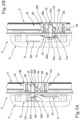
- the device 100 comprises a support element 10 that is inserted or insertable into a housing "T1," "A1" made in one between the frame “T” or the leaf “A” of the door or window.
- the support element 10 has a first wall 11a and a second wall 11b that is parallel to and opposite the first wall 11a.
- the first wall 11a faces externally the housing "A1", “T1”, whereas the second wall 11b is inserted inside the housing "A1", "T1".
- the support element 10 is made of metal, for example zamak, and is substantially box-shaped.
- the support element 10 has a substantially monolithic body provided with two side portions opposite a central portion.
- the side portions Preferably, the side portions have a lesser thickness than the thickness of the central portion.
- seats that are adapted to receive fixing means, for example screws to connect the support element 10 to the leaf “A” or to the fixed frame "T", are obtained in the side portions.
- a support seat 12 is obtained in the central portion.
- the support seat 12 is made on the first wall 11a of the support element 10 and extends through the support element 10 towards the second wall 11b.
- the support seat 12 has a circular section.
- the device 100 further comprises an adjustable pin 20 housed in the support seat 12.
- the pin 20 comprises a head end 21a protruding operationally from the support seat 12 and engageable with a guide "G" placed in a housing "T1", “A1” obtained in the other one between the frame “T” or the leaf “A”. Further, the pin 20 comprises a bottom end 21b inserted into the support seat 12. In use, when the leaf “A” is in the closed position, the adjustable pin 20 protrudes from the support element 10 by a sufficient amount for the head end 21a to engage the guide "G", so as to lock the leaf "A” in the closed position.
- the head end 21a protrudes from the support element 10 so as to compensate for the distance present between the uprights of the leaf "A” and of the fixed frame "T” due to the out-of-plumb position, so as to be inserted equally into the guide "G". In this situation, the head end 21a engages a locking portion "G1" of the guide “G” preventing sliding of the leaf "A” along the opening and closing direction "X", as will be disclosed in detail below.
- the adjustable pin 20 is movable along the support seat 12 to assume a plurality of stable positions comprised between a first maximum insertion position of the adjustable pin 20 in the support seat 12, and a second minimum insertion position of the adjustable pin 20 in the support seat 12.
- the adjustable pin 20 is movable between the first and the second position and vice versa by a translation motion along the support seat 12 (arrow “M" in figures 1A-1B ).
- the adjustable pin 20 is movable between the first and the second position and vice versa by a screwing motion along the support seat 12.
- the adjustable pin 20 comprises a main body 21c comprised between the head end 21a and the bottom end 21b.
- the main body 21c has, in cross section, a diameter equal to the diameter of the bottom end 21b, whereas the head end 21a has, in cross section, a greater diameter.
- the head end 21a abuts solidly on the locking portion "G1" of the guide “G", when the leaf "A" is locked in the closed position.
- the head end 21a, the bottom end 21b and/or the main body 21c have a substantially cylindrical conformation.
- the head end 21a can define a radial expansion relative to the bottom end 21b and/or to the main body 21c so as to enable the head end 21a to engage the locking portion "G1" of the guide “G", preventing sliding of the leaf "A" along the opening and closing direction "X".
- this radial expansion can extend at least partially along a direction that is transverse, preferably perpendicular, to the aforesaid opening and closing direction "X" and/or to a direction of extension of the aforesaid guide "G".
- the main body 21c comprises a first threaded portion 22a extending from the bottom end 21b and a second non-threaded portion 22b extending from the head end 21a.
- the first threaded portion 22a is configured to engage a respective threaded portion made within the support seat 12, such that the adjustable pin 20 can move between the first position and the second position and vice versa through a screwing/unscrewing motion.
- the first threaded portion 22a has a length that is about the same as the length of the support seat 12 so that the second non-threaded portion 22b projects from the support seat 12 also when the adjustable pin 20 is in the first maximum insertion position. This aspect enables the device 100 to be used also if there is no pronounced misalignment between the fixed frame "T" and the leaf "A".
- the adjustable pin 20 protrudes from the support seat 12 only by an amount that is equal to the length of the first non-threaded portion 22b.
- This length has a so-called “nominal” value (for example "design” value), i.e. the value that the adjustable pin 20 would require to lock the leaf "A” in the closed position if there were no anomalous space (airgap) to compensate between the fixed frame "T” and leaf "A", for example in the absence of an out-of-plumb position.
- the adjustable pin 20 In use, depending on the airgap present between the uprights of the fixed frame “T” and of the leaf "A”, when the latter is in the closed position (and thus, in the presence of anomalous inclinations, depending on the out-of-plumb position to be compensated), the adjustable pin 20 is moved along the support seat 12 to assume a position in which it can engage the guide "G” and ensure locking of the leaf "A" in the closed position.
- the possibility of adjusting the position of the adjustable pin 20 along the support seat 12 makes the device 100 adaptable to the airgap of the door or window, so as to compensate for abutment anomalies between the leaf and frame in closed conditions of the leaf that are for example caused by anomalous distances and/or inclinations, as in the presence of an out-of-plumb door or window.
- the position of the adjustable pin 20 along the support seat 12 is continuously adjustable between the first and the second position.
- the adjustable pin 20 can assume, during movement thereof along the support seat 12, any stable position comprised between the first and the second position.
- This aspect is particularly advantageous because it permits very precise and customizable adjustment of the adjustable pin 20.
- the possibility of adjusting the position of the continuously adjustable pin 20 permits a wide adjustment range of the airgap of the door or window so as to compensate for, also as far as neutralizing, the misalignments between the leaf "A" and the fixed frame “T” without inserting shims and/or replacing the pin with other pins of different length. This contributes to reducing the time and costs that are associated with the adjustment of the airgap of the door or window.
- the device 100 further comprises locking means 30 configured to lock the adjustable pin 20 in a set position that is stable between the aforesaid positions of maximum and minimum insertion.
- the locking means 30 hinders an accidental movement of the adjustable pin 20 in the support seat 12. In other words, once the position is established that the adjustable pin 20 has to assume within the support seat 12 to perform adjustment of the airgap of the door or window, the adjustable pin 20 is locked by the action of the locking means 30.
- the locking means 30 comprises a clamping seat 33 obtained in the support element 10 and extending transversely to the support seat 12, between an inlet section thereof placed on the first wall 11a of the support element 10 and an outlet section leading into the support seat 12.
- the locking means 30 comprises a locking grub screw 34 that is movable along the clamping seat 33 between an operating position, in which the locking grub screw 34 is placed near the outlet section to engage the adjustable pin 20 and prevent movement thereof, and a release position in which the locking grub screw 34 is distal from the outlet section to permit the adjustable pin 20 to move along the support seat 12.
- the locking grub screw 34 has an outer side surface provided with a thread configured to engage a respective counter-thread made between the clamping seat 33; further, the locking grub screw 34 has a substantially frustoconical head surface configured to impose pressure on a respective portion of the side surface of the adjustable pin 20, so as to avoid movement thereof, when the locking grub screw 34 is in the operating position. Still more preferably, the locking grub screw 34 comprises, on an outer surface accessible from the clamping seat 33, a shaped recess for receiving an adjusting means configured to move the locking grub screw 34 between the operating position and the release position along the clamping seat 33.
- the inclination of the clamping seat 33 relative to the adjustable pin 20 enables the adjustable pin 20 to be locked in an advantageously practical and simple manner.
- the locking means 30 comprises a clamping seat 33 obtained in the support element 10 and extending parallel to the support seat 12, and an auxiliary seat 35 that is transverse, preferably perpendicular, to the support seat 12 and to the clamping seat 33.
- the auxiliary seat can be made continuously with the clamping seat 33.
- the locking means 30 further comprises a wedge element 36 that is slidably inserted into the transverse auxiliary seat 35 and movable between an operating position, in which it is in contact with the adjustable pin 20 to impose a locking pressure, and a rest position, in which said wedge element 36 is moved away from the adjustable pin 20 to permit movement thereof.
- the locking means 30 further comprises a locking grub screw 34 inserted within the clamping seat 33 and suitable for exerting a thrust on the wedge element 36.
- the locking grub screw 34 exerts this thrust on an inclined portion of the wedge element 36, which faces the locking grub screw 34 itself.
- the locking grub screw 34 is movable between an operating position in which it abuts on the wedge element 36 (corresponding to the operating position of the wedge element 36), and a rest position in which the locking grub screw 34 is distal from the wedge element 36 (corresponding to the rest position of the wedge element 36).
- the locking grub screw 34 has a shaped recess for receiving an adjusting means configured to move the locking grub screw 34 between the operating position and the rest position along the clamping seat 33, so as to place the wedge element 36, respectively, in the operating position or in the rest position.
- the locking means 30 comprises a threadlocker 31 fitted to the adjustable pin 30.
- the threadlocker 31 is of the mechanical or chemical type. Still more preferably, the threadlocker 31 extends over the entire length of the support seat 12 and acts on the first threaded portion 22a of the main body 21c of the adjustable pin 20 inserted inside the support seat 12.
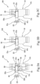
- Figure 3B illustrates a further non-claimed embodiment in which the locking means 30 comprises an o-ring 32 fitted on the adjustable pin 20.
- the adjustable pin 20 is provided with a circumferential recess for housing the o-ring 32.
- the circumferential recess is made on the inner wall of the support seat 12.
- At least one device 100 is installed on one between the leaf “A” and the fixed frame "T", whereas a respective guide “G” is installed on the other one between the leaf "A” or the fixed frame "T".
- the device 100 is fixed to the housing "A1" obtained on the leaf “A", whereas the guide “G” is inserted inside the housing "T1" obtained on the fixed frame “T”. More in detail, the device 100 is fixed to a control rod of the leaf “A” inserted into the cornice of the leaf "A”.
- the control rod is movable in translation along a vertical direction, and in particular perpendicular to the opening and closing direction "X".
- the control rod is movable between a raised position, to permit movement of the leaf "A” along the opening and closing direction "X", and a lowered position, to permit locking of the leaf "A” in the closed position.
- the locking means 30 is loosened to permit adjustment of the adjustable pin 20.
- the adjustable pin 20 is moved inside the support seat 12, so as to be arranged in a position that is suitable for compensating the reciprocal distance between the leaf "A” and the fixed frame "T", for example caused by an out-of-plumb position.
- the head end 21a of the adjustable pin 20 comprises a shaped housing 23 configured to receive an adjusting tool, for example a screwdriver or an Allen key, adapted to perform a movement of the adjustable pin 20 between the first and the second position.
- an adjusting tool for example a screwdriver or an Allen key
- the head end 21a of the adjustable pin 20 is inserted inside an insertion portion "G2" of the guide “G” ( figure 2A ). Afterwards, the control rod of the leaf “A” is moved in translation together with the device 100 towards the lowered position. In this situation, the adjustable pin 20 protrudes from the support seat 12 by an amount that is such that the head end 21a slides inside the guide “G” until it engages the locking portion "G1" of the guide "G".
- the locking portion “G1" is shaped and has a substantially trapezoidal shape so as to convey the head end 21a of the adjustable pin 20 progressively nearer a bottom wall of the guide “G” and thus so as to lock the leaf “A” in a closed position.
- the head end 21a protrudes from the support seat 12 to be correctly constrained on the guide “G” and thus prevent the adjustable pin 20, and thus the entire leaf “A” from moving along the opening and closing direction "X”, locking the leaf “A” in the closed position ( figure 2B ).
- the leaf “A” is locked correctly in the closed position, regardless of the presence of an anomalous distance between the leaf and the frame, for example caused by the out-of-plumb position.
- the anomalous distance has been compensated for by the adjustment of the position of the adjustable pin 20 within the support seat 12.
- the control rod is again moved in translation together with the device 100 towards the raised position, such that the head end 21a is moved towards the insertion portion "G2" of the guide “G".
- the head end 21a of the adjustable pin 20 slides along the locking portion “G1” of the guide “G”, releasing itself therefrom until it reaches the insertion portion "G2".
- the leaf "A” is free to slide along the opening and closing direction "X" to perform opening of the door or window.
- the device 100 is fixed to the housing "T1" obtained within the fixed frame "T", whereas the guide “G” is inserted inside the housing "A1” obtained in the leaf “A”, and more in particular within the control rod of the leaf “A” inside the cornice of the leaf.
- the guide “G” that moves along the vertical direction, so as to slide to offer the adjustable pin 20 respectively the insertion portion "G2" and the locking portion "G1".
- moving the adjustable pin 20 and the other features disclosed above remain substantially unchanged, only the installation of the device 100 between the leaf and frame being reversed.
- a lift-and-slide door or window comprising a fixed frame “T” that is mountable at a perimeter of a gap in masonry and having a vertical upright on which at least one housing "T1" is made is an object of this invention.
- the door or window further comprises a leaf “A” having a glass panel and a cornice for the glass panel, said cornice having a vertical upright on which at least one housing "A1" is made.
- the leaf “A” is slidable along an opening and closing direction "X" between a closed position, in which the vertical upright of the cornice abuts on the vertical upright of the fixed frame “T” to close the gap in the masonry, and an open position, in which the vertical upright of the cornice is moved away from the vertical upright of the fixed frame "T” to permit access to the gap in the masonry.
- the door or window further comprises at least one adjusting device 100 according to what has been disclosed and mounted in a housing "T1", “A1" of one between the leaf “A” and the fixed frame "T".
- the door or window further comprises at least one guide "G" mounted in the housing "T1", “A1" of the other one between leaf “A” and fixed frame “T” and configured to engage the head end 21a of the adjustable pin 20, when the leaf "A" is in the closed position.
- the door or window comprises two devices 100, one of which is arranged near a floor on which the leaf "A" slides and one is arranged near an upper cross member of the door or window.
- the devices 100 are adjustable independently of one another so as to make an adjustment of the airgap of the door or window more precise. If for example, because of being out-of-plumb, the upright of the leaf "A” and the upright of the fixed frame “T” diverge from one another upwards, the device 100 near the floor will have an adjustable pin 20 projecting minimally from the respective support seat 12 relative to the adjustable pin 20 of the device 100 placed near the upper cross member of the door or window, which will on the other hand project more from the seat 12.
- the adjustable pin 20 placed in the device 100 near the upper cross member of the door or window will have to in fact protrude further from the support seat 12, because it has to compensate for a greater space present between the uprights of the leaf "A” and of the fixed frame "T” to be able to engage the respective guide "G" correctly.
- An object of the present invention is moreover a method for compensating for an out-of-plumb position between a fixed frame "T" and a leaf "A" of a lift-and-slide door or window “S” comprising a step of acting directly on the adjustable pin 20 to move it between the first maximum insertion position and the second minimum insertion position in order to position the adjustable pin 20 in a compensation position comprised between said plurality of stable positions.
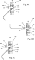
- an adjusting means like for example Allen keys, screwdrivers or the like, is inserted within the clamping seat 33 to take the locking grub screw 34 from an operating position, in which it imposes a locking force on the adjustable pin 20, to the release position in which it enables the adjustable pin 20 to be moved.
- the method comprises a step of moving the adjustable pin 20 between the first maximum insertion position and the second minimum insertion position to place the adjustable pin 20 in a compensation position comprised between the plurality of discrete positions ( figure 4B ).
- the head end 21a is engaged, via the shaped housing 23, by an adjusting means, like for example an Allen key, a screwdriver and the like.
- the adjustable pin 20 is movable between the first position and the second position by a screwing motion impressed by the adjusting means.
- the method can comprise a step of clamping the locking means 30 to lock the adjustable pin 20 in the compensation position.
- the method enables the airgap of the door or window to be adjusted easily and fast. Further, the method enables the time and costs to be reduced that are associated with the adjustment of the airgap of the door or window.
- the present invention achieves the proposed objects by eliminating the drawbacks that have emerged from the prior art and achieving important advantages.
- the possibility of adjusting continuously the position of the adjustable pin and of locking this pin in the desired portion by the locking means advantageously enables wide adjustment of the airgap of the door or window and thus precise compensation for the out-of-plumb position.
- the possibility of continuously adjusting the position of the adjustable pin and of locking this pin in the desired portion enables the time and the costs to be decreased that are associated with adjusting the airgap of the door or window to compensate for an out-of-plumb position, because there is no longer any need to have pins available that have different measurements and/or shim elements.
- the device 100 facilitates adjustment of the door or window by a skilled person even a considerable time after mounting.
Landscapes
- Hinges (AREA)
- Window Of Vehicle (AREA)
Claims (9)
- Hebeschiebetür oder Hebeschiebefenster, umfassend:- einen festen Rahmen (T), der am Umfang einer Fuge im Mauerwerk montierbar ist und einen vertikalen Pfosten umfasst, auf der mindestens ein Gehäuse (T1) angebracht ist;- einen Flügel (A), der eine Glasscheibe und ein Gesims für die Glasscheibe umfasst, wobei das Gesims einen vertikalen Pfosten aufweist, auf der mindestens ein Gehäuse (A1) angebracht ist; wobei der Flügel (A) entlang einer Öffnungs- und Schließrichtung (X) zwischen einer geschlossenen Position, in der der vertikale Pfosten des Gesimses an dem vertikalen Pfosten des festen Rahmens (T) anliegt, und einer offenen Position, in der der vertikale Pfosten des Gesimses von dem vertikalen Pfosten des Rahmens (T) wegbewegt wird, um Zugang zu der Fuge im Mauerwerk zu ermöglichen, verschiebbar ist;- mindestens eine Einstellvorrichtung (100) für eine Hebeschiebetür oder ein Hebeschiebefenster, die in dem einen Gehäuse (T1, A1) des Flügels (A) oder des festen Rahmens (T) montiert ist, wobei die Vorrichtung (100) Folgendes umfasst:- ein Stützelement (10), das in das Gehäuse (T1, A1) eingefügt ist, das in dem Rahmen (T) oder dem Flügel (A) vorgesehen ist, wobei das Stützelement (10) eine erste Wand (11a) und eine zweite Wand (11b), die im Wesentlichen gegenüber der ersten Wand (11a) liegt, aufweist;- einen Stützsitz (12), der an der ersten Wand (11a) des Stützelements (10) angebracht ist und sich durch das Stützelement (10) in Richtung der zweiten Wand (11b) erstreckt;- einen einstellbaren Stift (20), der im Stützsitz (12) untergebracht ist und ein Kopfende (21a), das betriebsmäßig vom Stützsitz (12) hervorsteht und in eine Führung (G) einrastbar ist, die in dem anderen Gehäuse (T1, A1) des Rahmens (T) oder des Flügels (A) vorgesehen ist, um den Flügel (A) in der geschlossenen Position zu arretieren, und ein unteres Ende (21b) umfasst, das in den Stützsitz (12) eingefügt ist, wobei der einstellbare Stift (20) entlang des Stützsitzes (12) beweglich ist, um eine Vielzahl von stabilen Positionen einzunehmen, die zwischen einer ersten maximalen Einfügeposition des einstellbaren Stifts (20) im Stützsitz (12) und einer zweiten minimalen Einfügeposition des einstellbaren Stifts (20) im Stützsitz (12) liegen;- ein Arretiermittel (30), das dazu konfiguriert ist, den einstellbaren Stift (20) in einer der stabilen Positionen im Stützsitz (12) zu arretieren;- mindestens eine Führung (G), die in dem anderen Gehäuse (T1, A1) des Flügels (A) oder des festen Rahmens (T) montiert und dazu konfiguriert ist, das Kopfende (21a) des einstellbaren Stifts (20) in Eingriff zu nehmen, wenn der Flügel (A) sich in der geschlossenen Position befindet;dadurch gekennzeichnet, dass das Arretiermittel (30) Folgendes umfasst:- einen Klemmsitz (33), der im Stützelement (10) ausgebildet ist und sich quer zum Stützsitz (12) zwischen einem Einlassabschnitt, der an der ersten Wand (11a) des Stützelements (10) vorgesehen ist, und einem Auslassabschnitt, der in den Stützsitz (12) hineinführt, erstreckt;- eine Sicherungsschraube (34), die entlang des Klemmsitzes (33) zwischen einer Betriebsposition, in der die Sicherungsschraube (34) in der Nähe des Auslassabschnitts vorgesehen ist, um den einstellbaren Stift (20) in Eingriff zu nehmen und dessen Bewegung zu verhindern, und einer Freigabeposition, in der sich die Sicherungsschraube (34) distal vom Auslassabschnitt befindet, um eine Bewegung des einstellbaren Stifts (20) zu ermöglichen, beweglich ist.
- Tür oder Fenster nach Anspruch 1, wobei die Position des einstellbaren Stifts (20) entlang des Stützsitzes (12) kontinuierlich zwischen der ersten Position und der zweiten Position einstellbar ist.
- Tür oder Fenster nach Anspruch 1 oder 2, wobei der einstellbare Stift (20) durch eine Translationsbewegung zwischen der ersten Position und der zweiten Position und umgekehrt beweglich ist.
- Tür oder Fenster nach Anspruch 1 oder 2, wobei der einstellbare Stift (20) durch eine Schraubbewegung zwischen der ersten Position und der zweiten Position und umgekehrt beweglich ist.
- Tür oder Fenster nach Anspruch 4, wobei der einstellbare Stift (20) einen Hauptkörper (21c) umfasst, der zwischen dem Kopfende (21a) und dem unteren Ende (21b) liegt, wobei der Hauptkörper (21c) einen ersten Gewindeabschnitt (22a), der sich vom unteren Ende (21b) erstreckt, und einen zweiten gewindelosen Abschnitt (22b), der sich vom Kopfende (21a) erstreckt, aufweist.
- Tür oder Fenster nach Anspruch 5, wobei der erste Gewindeabschnitt (22a) eine Länge aufweist, die etwa der Länge des Stützsitzes (12) entspricht, so dass der zweite gewindelose Abschnitt (22b) vom Stützsitz (12) hervorsteht, auch wenn sich der einstellbare Stift (20) in der ersten maximalen Einfügeposition des einstellbaren Stifts (20) im Stützsitz (12) befindet.
- Tür oder Fenster nach einem der vorhergehenden Ansprüche, wobei der einstellbare Stift (20) am Kopfende (21a) ein geformtes Gehäuse (23) umfasst, das dazu konfiguriert ist, ein Einstellwerkzeug aufzunehmen, das dazu ausgelegt ist, den einstellbaren Stift (20) zwischen der ersten und der zweiten Position zu bewegen.
- Verfahren zum Einstellen einer Hebeschiebetür oder eines Hebeschiebefensters nach einem der Ansprüche 1 bis 7, wobei das Verfahren den Schritt des direkten Einwirkens auf den einstellbaren Stift (20) umfasst, um ihn zwischen der ersten maximalen Einfügeposition und der zweiten minimalen Einfügeposition zu bewegen, um den einstellbaren Stift (20) in einer Ausgleichsposition zu positionieren, die zwischen der Vielzahl von stabilen Positionen liegt.
- Verfahren nach Anspruch 8, das ferner die folgenden Schritte umfasst:- Lösen des Arretiermittels (30) zum Arretieren der Einstellvorrichtung (100) vor dem Schritt des Einwirkens auf den einstellbaren Stift (20);- Festklemmen des Arretiermittels (30) nach dem Schritt des Einwirkens auf den einstellbaren Stift (20), um ihn in der Ausgleichsposition zu arretieren.
Applications Claiming Priority (1)
| Application Number | Priority Date | Filing Date | Title |
|---|---|---|---|
| IT202100006593 | 2021-03-18 |
Publications (2)
| Publication Number | Publication Date |
|---|---|
| EP4060149A1 EP4060149A1 (de) | 2022-09-21 |
| EP4060149B1 true EP4060149B1 (de) | 2024-05-08 |
Family
ID=80121640
Family Applications (1)
| Application Number | Title | Priority Date | Filing Date |
|---|---|---|---|
| EP22162793.8A Active EP4060149B1 (de) | 2021-03-18 | 2022-03-17 | Hebe-schiebetür oder fenster und einstellverfahren |
Country Status (1)
| Country | Link |
|---|---|
| EP (1) | EP4060149B1 (de) |
Citations (1)
| Publication number | Priority date | Publication date | Assignee | Title |
|---|---|---|---|---|
| DE102016119515A1 (de) * | 2016-01-18 | 2017-07-20 | Hautau Gmbh | Beschlag für eine Schiebetür, Schiebetüreinheit, Verfahren zum Öffnen einer Schiebetür und Verfahren zum Schließen einer Schiebetür |
Family Cites Families (7)
| Publication number | Priority date | Publication date | Assignee | Title |
|---|---|---|---|---|
| DE2553645A1 (de) * | 1975-11-28 | 1977-06-08 | Hautau Baubeschlag | Treibstangenbeschlag fuer fluegel von fenstern, tueren o.dgl. |
| FR2591267B1 (fr) * | 1985-12-06 | 1988-02-05 | Ferco Int Usine Ferrures | Ferrure de verrouillage avec pene reglable pour un ouvrant coulissant de fenetre, porte ou analogue |
| IT1234029B (it) * | 1989-03-15 | 1992-04-24 | Giesse Spa | Dispositivo perfezionato per la regolazione della posizione operativa del catenaccio ad aggancio di ante scorrevoli di porte, finestre e simili |
| DE19916220B4 (de) * | 1999-04-10 | 2011-05-05 | Aug. Winkhaus Gmbh & Co. Kg | Schließzapfen |
| DE102006000063A1 (de) * | 2006-01-27 | 2007-08-02 | Siegenia-Aubi Kg | Verschlussbolzen |
| ITBO20070177A1 (it) * | 2007-03-14 | 2008-09-15 | Gsg Int Spa | Infisso scorrevole. |
| GB2567576B (en) * | 2011-11-11 | 2019-07-17 | Assa Abloy Ltd | Multipoint lock with adjustable connecting rod linkage |
-
2022
- 2022-03-17 EP EP22162793.8A patent/EP4060149B1/de active Active
Patent Citations (1)
| Publication number | Priority date | Publication date | Assignee | Title |
|---|---|---|---|---|
| DE102016119515A1 (de) * | 2016-01-18 | 2017-07-20 | Hautau Gmbh | Beschlag für eine Schiebetür, Schiebetüreinheit, Verfahren zum Öffnen einer Schiebetür und Verfahren zum Schließen einer Schiebetür |
Also Published As
| Publication number | Publication date |
|---|---|
| EP4060149A1 (de) | 2022-09-21 |
Similar Documents
| Publication | Publication Date | Title |
|---|---|---|
| CA2851450C (en) | Adjustable door mounting system | |
| CA2364823C (en) | Casement window with improved tie bar guide and striker | |
| US5483770A (en) | Door or window mountings | |
| US8413299B2 (en) | Hinge for door or window | |
| EP3112570A1 (de) | Schliesssatz für schiebetür | |
| US20200048944A1 (en) | Hinge for a door or window | |
| US9187941B2 (en) | Roller assembly for sliding door | |
| US20160177619A1 (en) | Corner fitting with adjustable restraining area | |
| US20190264485A1 (en) | Upwardly Pivoted Window with Spring Biased Sash | |
| EP3944799A1 (de) | Einstellbare türrahmenanordnung, installationsverfahren und duschtürinstallationsstruktur | |
| EP4060149A1 (de) | Hebe-schiebetür oder fenster und einstellverfahren | |
| EP3321458B1 (de) | Scharnieranordnung, insbesondere eine verdeckte scharnieranordnung | |
| US7260915B2 (en) | Door seal device | |
| WO2001094730A1 (en) | Friction hinge & window fitting | |
| EP2927407B1 (de) | Scharnier | |
| US20090282742A1 (en) | Roller assembly for sliding door | |
| US9856693B2 (en) | Corner fitting with variably adjustable restraining area | |
| CA3020835C (en) | End load arm | |
| IE53761B1 (en) | Improvements in strikers for locks | |
| AU2015264825B2 (en) | Adjustable corner fitting with holding element | |
| EP4124712A1 (de) | Scharnier für eine tür oder ein fenster und verfahren zur montage des scharniers an einer tür oder einem fenster | |
| CN111279043A (zh) | 带部件 | |
| EP4155492B1 (de) | Scharnier sowie türanordnung mit scharnier | |
| CN111648661B (zh) | 门锁定设备 | |
| US20250003273A1 (en) | Hinge for window or door |
Legal Events
| Date | Code | Title | Description |
|---|---|---|---|
| PUAI | Public reference made under article 153(3) epc to a published international application that has entered the european phase |
Free format text: ORIGINAL CODE: 0009012 |
|
| STAA | Information on the status of an ep patent application or granted ep patent |
Free format text: STATUS: THE APPLICATION HAS BEEN PUBLISHED |
|
| AK | Designated contracting states |
Kind code of ref document: A1 Designated state(s): AL AT BE BG CH CY CZ DE DK EE ES FI FR GB GR HR HU IE IS IT LI LT LU LV MC MK MT NL NO PL PT RO RS SE SI SK SM TR |
|
| STAA | Information on the status of an ep patent application or granted ep patent |
Free format text: STATUS: REQUEST FOR EXAMINATION WAS MADE |
|
| 17P | Request for examination filed |
Effective date: 20230228 |
|
| RBV | Designated contracting states (corrected) |
Designated state(s): AL AT BE BG CH CY CZ DE DK EE ES FI FR GB GR HR HU IE IS IT LI LT LU LV MC MK MT NL NO PL PT RO RS SE SI SK SM TR |
|
| P01 | Opt-out of the competence of the unified patent court (upc) registered |
Effective date: 20230523 |
|
| STAA | Information on the status of an ep patent application or granted ep patent |
Free format text: STATUS: EXAMINATION IS IN PROGRESS |
|
| 17Q | First examination report despatched |
Effective date: 20230823 |
|
| GRAP | Despatch of communication of intention to grant a patent |
Free format text: ORIGINAL CODE: EPIDOSNIGR1 |
|
| STAA | Information on the status of an ep patent application or granted ep patent |
Free format text: STATUS: GRANT OF PATENT IS INTENDED |
|
| GRAS | Grant fee paid |
Free format text: ORIGINAL CODE: EPIDOSNIGR3 |
|
| GRAA | (expected) grant |
Free format text: ORIGINAL CODE: 0009210 |
|
| STAA | Information on the status of an ep patent application or granted ep patent |
Free format text: STATUS: THE PATENT HAS BEEN GRANTED |
|
| INTG | Intention to grant announced |
Effective date: 20240314 |
|
| AK | Designated contracting states |
Kind code of ref document: B1 Designated state(s): AL AT BE BG CH CY CZ DE DK EE ES FI FR GB GR HR HU IE IS IT LI LT LU LV MC MK MT NL NO PL PT RO RS SE SI SK SM TR |
|
| REG | Reference to a national code |
Ref country code: GB Ref legal event code: FG4D |
|
| REG | Reference to a national code |
Ref country code: CH Ref legal event code: EP |
|
| REG | Reference to a national code |
Ref country code: DE Ref legal event code: R096 Ref document number: 602022003278 Country of ref document: DE |
|
| REG | Reference to a national code |
Ref country code: IE Ref legal event code: FG4D |
|
| REG | Reference to a national code |
Ref country code: NL Ref legal event code: FP |
|
| REG | Reference to a national code |
Ref country code: LT Ref legal event code: MG9D |
|
| PG25 | Lapsed in a contracting state [announced via postgrant information from national office to epo] |
Ref country code: IS Free format text: LAPSE BECAUSE OF FAILURE TO SUBMIT A TRANSLATION OF THE DESCRIPTION OR TO PAY THE FEE WITHIN THE PRESCRIBED TIME-LIMIT Effective date: 20240908 |
|
| PG25 | Lapsed in a contracting state [announced via postgrant information from national office to epo] |
Ref country code: BG Free format text: LAPSE BECAUSE OF FAILURE TO SUBMIT A TRANSLATION OF THE DESCRIPTION OR TO PAY THE FEE WITHIN THE PRESCRIBED TIME-LIMIT Effective date: 20240508 |
|
| PG25 | Lapsed in a contracting state [announced via postgrant information from national office to epo] |
Ref country code: FI Free format text: LAPSE BECAUSE OF FAILURE TO SUBMIT A TRANSLATION OF THE DESCRIPTION OR TO PAY THE FEE WITHIN THE PRESCRIBED TIME-LIMIT Effective date: 20240508 Ref country code: HR Free format text: LAPSE BECAUSE OF FAILURE TO SUBMIT A TRANSLATION OF THE DESCRIPTION OR TO PAY THE FEE WITHIN THE PRESCRIBED TIME-LIMIT Effective date: 20240508 |
|
| PG25 | Lapsed in a contracting state [announced via postgrant information from national office to epo] |
Ref country code: GR Free format text: LAPSE BECAUSE OF FAILURE TO SUBMIT A TRANSLATION OF THE DESCRIPTION OR TO PAY THE FEE WITHIN THE PRESCRIBED TIME-LIMIT Effective date: 20240809 |
|
| PG25 | Lapsed in a contracting state [announced via postgrant information from national office to epo] |
Ref country code: PT Free format text: LAPSE BECAUSE OF FAILURE TO SUBMIT A TRANSLATION OF THE DESCRIPTION OR TO PAY THE FEE WITHIN THE PRESCRIBED TIME-LIMIT Effective date: 20240909 |
|
| PG25 | Lapsed in a contracting state [announced via postgrant information from national office to epo] |
Ref country code: ES Free format text: LAPSE BECAUSE OF FAILURE TO SUBMIT A TRANSLATION OF THE DESCRIPTION OR TO PAY THE FEE WITHIN THE PRESCRIBED TIME-LIMIT Effective date: 20240508 |
|
| PG25 | Lapsed in a contracting state [announced via postgrant information from national office to epo] |
Ref country code: PL Free format text: LAPSE BECAUSE OF FAILURE TO SUBMIT A TRANSLATION OF THE DESCRIPTION OR TO PAY THE FEE WITHIN THE PRESCRIBED TIME-LIMIT Effective date: 20240508 |
|
| PG25 | Lapsed in a contracting state [announced via postgrant information from national office to epo] |
Ref country code: LV Free format text: LAPSE BECAUSE OF FAILURE TO SUBMIT A TRANSLATION OF THE DESCRIPTION OR TO PAY THE FEE WITHIN THE PRESCRIBED TIME-LIMIT Effective date: 20240508 |
|
| PG25 | Lapsed in a contracting state [announced via postgrant information from national office to epo] |
Ref country code: PT Free format text: LAPSE BECAUSE OF FAILURE TO SUBMIT A TRANSLATION OF THE DESCRIPTION OR TO PAY THE FEE WITHIN THE PRESCRIBED TIME-LIMIT Effective date: 20240909 Ref country code: PL Free format text: LAPSE BECAUSE OF FAILURE TO SUBMIT A TRANSLATION OF THE DESCRIPTION OR TO PAY THE FEE WITHIN THE PRESCRIBED TIME-LIMIT Effective date: 20240508 Ref country code: NO Free format text: LAPSE BECAUSE OF FAILURE TO SUBMIT A TRANSLATION OF THE DESCRIPTION OR TO PAY THE FEE WITHIN THE PRESCRIBED TIME-LIMIT Effective date: 20240808 Ref country code: LV Free format text: LAPSE BECAUSE OF FAILURE TO SUBMIT A TRANSLATION OF THE DESCRIPTION OR TO PAY THE FEE WITHIN THE PRESCRIBED TIME-LIMIT Effective date: 20240508 Ref country code: IS Free format text: LAPSE BECAUSE OF FAILURE TO SUBMIT A TRANSLATION OF THE DESCRIPTION OR TO PAY THE FEE WITHIN THE PRESCRIBED TIME-LIMIT Effective date: 20240908 Ref country code: HR Free format text: LAPSE BECAUSE OF FAILURE TO SUBMIT A TRANSLATION OF THE DESCRIPTION OR TO PAY THE FEE WITHIN THE PRESCRIBED TIME-LIMIT Effective date: 20240508 Ref country code: GR Free format text: LAPSE BECAUSE OF FAILURE TO SUBMIT A TRANSLATION OF THE DESCRIPTION OR TO PAY THE FEE WITHIN THE PRESCRIBED TIME-LIMIT Effective date: 20240809 Ref country code: FI Free format text: LAPSE BECAUSE OF FAILURE TO SUBMIT A TRANSLATION OF THE DESCRIPTION OR TO PAY THE FEE WITHIN THE PRESCRIBED TIME-LIMIT Effective date: 20240508 Ref country code: ES Free format text: LAPSE BECAUSE OF FAILURE TO SUBMIT A TRANSLATION OF THE DESCRIPTION OR TO PAY THE FEE WITHIN THE PRESCRIBED TIME-LIMIT Effective date: 20240508 Ref country code: BG Free format text: LAPSE BECAUSE OF FAILURE TO SUBMIT A TRANSLATION OF THE DESCRIPTION OR TO PAY THE FEE WITHIN THE PRESCRIBED TIME-LIMIT Effective date: 20240508 Ref country code: RS Free format text: LAPSE BECAUSE OF FAILURE TO SUBMIT A TRANSLATION OF THE DESCRIPTION OR TO PAY THE FEE WITHIN THE PRESCRIBED TIME-LIMIT Effective date: 20240808 |
|
| REG | Reference to a national code |
Ref country code: AT Ref legal event code: UEP Ref document number: 1685117 Country of ref document: AT Kind code of ref document: T Effective date: 20240508 |
|
| PG25 | Lapsed in a contracting state [announced via postgrant information from national office to epo] |
Ref country code: DK Free format text: LAPSE BECAUSE OF FAILURE TO SUBMIT A TRANSLATION OF THE DESCRIPTION OR TO PAY THE FEE WITHIN THE PRESCRIBED TIME-LIMIT Effective date: 20240508 |
|
| PG25 | Lapsed in a contracting state [announced via postgrant information from national office to epo] |
Ref country code: EE Free format text: LAPSE BECAUSE OF FAILURE TO SUBMIT A TRANSLATION OF THE DESCRIPTION OR TO PAY THE FEE WITHIN THE PRESCRIBED TIME-LIMIT Effective date: 20240508 |
|
| PG25 | Lapsed in a contracting state [announced via postgrant information from national office to epo] |
Ref country code: CZ Free format text: LAPSE BECAUSE OF FAILURE TO SUBMIT A TRANSLATION OF THE DESCRIPTION OR TO PAY THE FEE WITHIN THE PRESCRIBED TIME-LIMIT Effective date: 20240508 |
|
| PG25 | Lapsed in a contracting state [announced via postgrant information from national office to epo] |
Ref country code: SK Free format text: LAPSE BECAUSE OF FAILURE TO SUBMIT A TRANSLATION OF THE DESCRIPTION OR TO PAY THE FEE WITHIN THE PRESCRIBED TIME-LIMIT Effective date: 20240508 Ref country code: RO Free format text: LAPSE BECAUSE OF FAILURE TO SUBMIT A TRANSLATION OF THE DESCRIPTION OR TO PAY THE FEE WITHIN THE PRESCRIBED TIME-LIMIT Effective date: 20240508 |
|
| PG25 | Lapsed in a contracting state [announced via postgrant information from national office to epo] |
Ref country code: SM Free format text: LAPSE BECAUSE OF FAILURE TO SUBMIT A TRANSLATION OF THE DESCRIPTION OR TO PAY THE FEE WITHIN THE PRESCRIBED TIME-LIMIT Effective date: 20240508 |
|
| PG25 | Lapsed in a contracting state [announced via postgrant information from national office to epo] |
Ref country code: SM Free format text: LAPSE BECAUSE OF FAILURE TO SUBMIT A TRANSLATION OF THE DESCRIPTION OR TO PAY THE FEE WITHIN THE PRESCRIBED TIME-LIMIT Effective date: 20240508 Ref country code: SK Free format text: LAPSE BECAUSE OF FAILURE TO SUBMIT A TRANSLATION OF THE DESCRIPTION OR TO PAY THE FEE WITHIN THE PRESCRIBED TIME-LIMIT Effective date: 20240508 Ref country code: RO Free format text: LAPSE BECAUSE OF FAILURE TO SUBMIT A TRANSLATION OF THE DESCRIPTION OR TO PAY THE FEE WITHIN THE PRESCRIBED TIME-LIMIT Effective date: 20240508 Ref country code: EE Free format text: LAPSE BECAUSE OF FAILURE TO SUBMIT A TRANSLATION OF THE DESCRIPTION OR TO PAY THE FEE WITHIN THE PRESCRIBED TIME-LIMIT Effective date: 20240508 Ref country code: DK Free format text: LAPSE BECAUSE OF FAILURE TO SUBMIT A TRANSLATION OF THE DESCRIPTION OR TO PAY THE FEE WITHIN THE PRESCRIBED TIME-LIMIT Effective date: 20240508 Ref country code: CZ Free format text: LAPSE BECAUSE OF FAILURE TO SUBMIT A TRANSLATION OF THE DESCRIPTION OR TO PAY THE FEE WITHIN THE PRESCRIBED TIME-LIMIT Effective date: 20240508 |
|
| REG | Reference to a national code |
Ref country code: DE Ref legal event code: R097 Ref document number: 602022003278 Country of ref document: DE |
|
| PLBE | No opposition filed within time limit |
Free format text: ORIGINAL CODE: 0009261 |
|
| STAA | Information on the status of an ep patent application or granted ep patent |
Free format text: STATUS: NO OPPOSITION FILED WITHIN TIME LIMIT |
|
| 26N | No opposition filed |
Effective date: 20250211 |
|
| PG25 | Lapsed in a contracting state [announced via postgrant information from national office to epo] |
Ref country code: SI Free format text: LAPSE BECAUSE OF FAILURE TO SUBMIT A TRANSLATION OF THE DESCRIPTION OR TO PAY THE FEE WITHIN THE PRESCRIBED TIME-LIMIT Effective date: 20240508 |
|
| PG25 | Lapsed in a contracting state [announced via postgrant information from national office to epo] |
Ref country code: SE Free format text: LAPSE BECAUSE OF FAILURE TO SUBMIT A TRANSLATION OF THE DESCRIPTION OR TO PAY THE FEE WITHIN THE PRESCRIBED TIME-LIMIT Effective date: 20240508 |
|
| PG25 | Lapsed in a contracting state [announced via postgrant information from national office to epo] |
Ref country code: MC Free format text: LAPSE BECAUSE OF FAILURE TO SUBMIT A TRANSLATION OF THE DESCRIPTION OR TO PAY THE FEE WITHIN THE PRESCRIBED TIME-LIMIT Effective date: 20240508 |
|
| REG | Reference to a national code |
Ref country code: CH Ref legal event code: H13 Free format text: ST27 STATUS EVENT CODE: U-0-0-H10-H13 (AS PROVIDED BY THE NATIONAL OFFICE) Effective date: 20251023 |
|
| PG25 | Lapsed in a contracting state [announced via postgrant information from national office to epo] |
Ref country code: LU Free format text: LAPSE BECAUSE OF NON-PAYMENT OF DUE FEES Effective date: 20250317 |
|
| PG25 | Lapsed in a contracting state [announced via postgrant information from national office to epo] |
Ref country code: FR Free format text: LAPSE BECAUSE OF NON-PAYMENT OF DUE FEES Effective date: 20250331 |
|
| PG25 | Lapsed in a contracting state [announced via postgrant information from national office to epo] |
Ref country code: CH Free format text: LAPSE BECAUSE OF NON-PAYMENT OF DUE FEES Effective date: 20250331 |
|
| PG25 | Lapsed in a contracting state [announced via postgrant information from national office to epo] |
Ref country code: IE Free format text: LAPSE BECAUSE OF NON-PAYMENT OF DUE FEES Effective date: 20250317 |
|
| PGFP | Annual fee paid to national office [announced via postgrant information from national office to epo] |
Ref country code: DE Payment date: 20260320 Year of fee payment: 5 |
|
| PGFP | Annual fee paid to national office [announced via postgrant information from national office to epo] |
Ref country code: AT Payment date: 20260301 Year of fee payment: 5 |
|
| PGFP | Annual fee paid to national office [announced via postgrant information from national office to epo] |
Ref country code: BE Payment date: 20260323 Year of fee payment: 5 Ref country code: IT Payment date: 20260319 Year of fee payment: 5 |
|
| PGFP | Annual fee paid to national office [announced via postgrant information from national office to epo] |
Ref country code: NL Payment date: 20260323 Year of fee payment: 5 |