EP4060444A1 - Dispositif d'entraînement autonome, procédé d'entraînement autonome et pluralité de supports de stockage non transitoires - Google Patents
Dispositif d'entraînement autonome, procédé d'entraînement autonome et pluralité de supports de stockage non transitoires Download PDFInfo
- Publication number
- EP4060444A1 EP4060444A1 EP22160426.7A EP22160426A EP4060444A1 EP 4060444 A1 EP4060444 A1 EP 4060444A1 EP 22160426 A EP22160426 A EP 22160426A EP 4060444 A1 EP4060444 A1 EP 4060444A1
- Authority
- EP
- European Patent Office
- Prior art keywords
- ecu
- autonomous driving
- vehicle
- remote control
- power saving
- Prior art date
- Legal status (The legal status is an assumption and is not a legal conclusion. Google has not performed a legal analysis and makes no representation as to the accuracy of the status listed.)
- Granted
Links
Images


Classifications
-
- G—PHYSICS
- G05—CONTROLLING; REGULATING
- G05D—SYSTEMS FOR CONTROLLING OR REGULATING NON-ELECTRIC VARIABLES
- G05D1/00—Control of position, course, altitude or attitude of land, water, air or space vehicles, e.g. using automatic pilots
- G05D1/0011—Control of position, course, altitude or attitude of land, water, air or space vehicles, e.g. using automatic pilots associated with a remote control arrangement
-
- B—PERFORMING OPERATIONS; TRANSPORTING
- B60—VEHICLES IN GENERAL
- B60W—CONJOINT CONTROL OF VEHICLE SUB-UNITS OF DIFFERENT TYPE OR DIFFERENT FUNCTION; CONTROL SYSTEMS SPECIALLY ADAPTED FOR HYBRID VEHICLES; ROAD VEHICLE DRIVE CONTROL SYSTEMS FOR PURPOSES NOT RELATED TO THE CONTROL OF A PARTICULAR SUB-UNIT
- B60W60/00—Drive control systems specially adapted for autonomous road vehicles
- B60W60/005—Handover processes
-
- B—PERFORMING OPERATIONS; TRANSPORTING
- B60—VEHICLES IN GENERAL
- B60W—CONJOINT CONTROL OF VEHICLE SUB-UNITS OF DIFFERENT TYPE OR DIFFERENT FUNCTION; CONTROL SYSTEMS SPECIALLY ADAPTED FOR HYBRID VEHICLES; ROAD VEHICLE DRIVE CONTROL SYSTEMS FOR PURPOSES NOT RELATED TO THE CONTROL OF A PARTICULAR SUB-UNIT
- B60W50/00—Details of control systems for road vehicle drive control not related to the control of a particular sub-unit, e.g. process diagnostic or vehicle driver interfaces
-
- B—PERFORMING OPERATIONS; TRANSPORTING
- B60—VEHICLES IN GENERAL
- B60W—CONJOINT CONTROL OF VEHICLE SUB-UNITS OF DIFFERENT TYPE OR DIFFERENT FUNCTION; CONTROL SYSTEMS SPECIALLY ADAPTED FOR HYBRID VEHICLES; ROAD VEHICLE DRIVE CONTROL SYSTEMS FOR PURPOSES NOT RELATED TO THE CONTROL OF A PARTICULAR SUB-UNIT
- B60W20/00—Control systems specially adapted for hybrid vehicles
- B60W20/10—Controlling the power contribution of each of the prime movers to meet required power demand
- B60W20/13—Controlling the power contribution of each of the prime movers to meet required power demand in order to stay within battery power input or output limits; in order to prevent overcharging or battery depletion
-
- B—PERFORMING OPERATIONS; TRANSPORTING
- B60—VEHICLES IN GENERAL
- B60W—CONJOINT CONTROL OF VEHICLE SUB-UNITS OF DIFFERENT TYPE OR DIFFERENT FUNCTION; CONTROL SYSTEMS SPECIALLY ADAPTED FOR HYBRID VEHICLES; ROAD VEHICLE DRIVE CONTROL SYSTEMS FOR PURPOSES NOT RELATED TO THE CONTROL OF A PARTICULAR SUB-UNIT
- B60W20/00—Control systems specially adapted for hybrid vehicles
- B60W20/20—Control strategies involving selection of hybrid configuration, e.g. selection between series or parallel configuration
-
- B—PERFORMING OPERATIONS; TRANSPORTING
- B60—VEHICLES IN GENERAL
- B60W—CONJOINT CONTROL OF VEHICLE SUB-UNITS OF DIFFERENT TYPE OR DIFFERENT FUNCTION; CONTROL SYSTEMS SPECIALLY ADAPTED FOR HYBRID VEHICLES; ROAD VEHICLE DRIVE CONTROL SYSTEMS FOR PURPOSES NOT RELATED TO THE CONTROL OF A PARTICULAR SUB-UNIT
- B60W60/00—Drive control systems specially adapted for autonomous road vehicles
-
- G—PHYSICS
- G05—CONTROLLING; REGULATING
- G05D—SYSTEMS FOR CONTROLLING OR REGULATING NON-ELECTRIC VARIABLES
- G05D1/00—Control of position, course, altitude or attitude of land, water, air or space vehicles, e.g. using automatic pilots
- G05D1/20—Control system inputs
- G05D1/22—Command input arrangements
- G05D1/221—Remote-control arrangements
- G05D1/227—Handing over between remote control and on-board control; Handing over between remote control arrangements
-
- G—PHYSICS
- G06—COMPUTING OR CALCULATING; COUNTING
- G06F—ELECTRIC DIGITAL DATA PROCESSING
- G06F1/00—Details not covered by groups G06F3/00 - G06F13/00 and G06F21/00
- G06F1/26—Power supply means, e.g. regulation thereof
- G06F1/32—Means for saving power
- G06F1/3203—Power management, i.e. event-based initiation of a power-saving mode
- G06F1/3234—Power saving characterised by the action undertaken
- G06F1/3287—Power saving characterised by the action undertaken by switching off individual functional units in the computer system
-
- G—PHYSICS
- G07—CHECKING-DEVICES
- G07C—TIME OR ATTENDANCE REGISTERS; REGISTERING OR INDICATING THE WORKING OF MACHINES; GENERATING RANDOM NUMBERS; VOTING OR LOTTERY APPARATUS; ARRANGEMENTS, SYSTEMS OR APPARATUS FOR CHECKING NOT PROVIDED FOR ELSEWHERE
- G07C5/00—Registering or indicating the working of vehicles
- G07C5/008—Registering or indicating the working of vehicles communicating information to a remotely located station
-
- B—PERFORMING OPERATIONS; TRANSPORTING
- B60—VEHICLES IN GENERAL
- B60W—CONJOINT CONTROL OF VEHICLE SUB-UNITS OF DIFFERENT TYPE OR DIFFERENT FUNCTION; CONTROL SYSTEMS SPECIALLY ADAPTED FOR HYBRID VEHICLES; ROAD VEHICLE DRIVE CONTROL SYSTEMS FOR PURPOSES NOT RELATED TO THE CONTROL OF A PARTICULAR SUB-UNIT
- B60W2510/00—Input parameters relating to a particular sub-units
- B60W2510/08—Electric propulsion units
Definitions
- the present invention relates to an autonomous driving device, an autonomous driving method, and a plurality of non-transitory storage media.
- JP 2018-077649 A discloses a technology relating to remote control on an autonomous driving vehicle. According to this technology, when autonomous driving is difficult, the vehicle and remote control management equipment communicate with each other to remotely drive the vehicle by a remote operator.
- an electronic control unit (ECU) for autonomous driving and an ECU for remote control may be mounted separately.
- ECU electronice control unit
- each application consumes a large amount of computational resources, which imposes a high load on the ECU. Therefore, a high-performance ECU is required, which leads to an increase in costs.
- the ECU goes down in the latter case, neither the autonomous driving nor the remote control can be performed. That is, the former method is realistic from the viewpoint of costs and fail-safe.
- the present disclosure provides a technology capable of reducing power consumptions of ECUs in a vehicle capable of autonomous driving and remote control.
- a first aspect of the present disclosure relates to an autonomous driving device to be mounted on a vehicle.
- the autonomous driving device includes a first ECU configured to autonomously drive the vehicle, and a second ECU configured to operate the vehicle under remote control from an outside.
- the first ECU is configured to keep an activated state while the second ECU is operating the vehicle.
- the second ECU is configured to keep a power saving state while the first ECU is autonomously driving the vehicle.
- the second ECU may be configured to make transition from the power saving state to an activated state in response to an activation instruction from the first ECU, and make transition from the activated state to the power saving state in response to a power saving instruction from the first ECU.
- the autonomous driving device may further include a third ECU configured to arbitrate control information to be output from the first ECU and control information to be output from the second ECU when the remote control is switched to autonomous driving or the autonomous driving is switched to the remote control.
- a third ECU configured to arbitrate control information to be output from the first ECU and control information to be output from the second ECU when the remote control is switched to autonomous driving or the autonomous driving is switched to the remote control.
- a second aspect of the present disclosure relates to an autonomous driving method for autonomously driving a vehicle by at least two ECUs.
- the autonomous driving method includes autonomously driving the vehicle by a first ECU, operating the vehicle under remote control from an outside by a second ECU, keeping the first ECU in an activated state while the second ECU is operating the vehicle, and keeping the second ECU in a power saving state while the first ECU is autonomously driving the vehicle.
- the autonomous driving method may further include making transition of the second ECU from the power saving state to an activated state in response to an activation instruction from the first ECU, and making transition of the second ECU from the activated state to the power saving state in response to a power saving instruction from the first ECU.
- the autonomous driving method may further include arbitrating, by a third ECU, control information to be output from the first ECU and control information to be output from the second ECU when the remote control is switched to autonomous driving or the autonomous driving is switched to the remote control.
- a third aspect of the present disclosure relates to a plurality of non-transitory storage media.
- the non-transitory storage media include a first non-transitory storage medium storing instructions that are executable by a first ECU mounted on a vehicle and that cause the first ECU to perform a first function, and a second non-transitory storage medium storing instructions that are executable by a second ECU mounted on the vehicle and that cause the second ECU to perform a second function.
- the first function includes autonomously driving the vehicle, and keeping the first ECU in an activated state while the second ECU is operating the vehicle.
- the second function includes operating the vehicle under remote control from an outside, and keeping the second ECU in a power saving state while the first ECU is autonomously driving the vehicle.
- the first function may include outputting an activation instruction to the second ECU, and outputting a power saving instruction to the second ECU.
- the second function may include making transition from the power saving state to an activated state in response to the activation instruction from the first ECU, and making transition from the activated state to the power saving state in response to the power saving instruction from the first ECU.
- the non-transitory storage media may further include a third non-transitory storage medium storing instructions that are executable by a third ECU and that cause the third ECU to arbitrate control information to be output from the first ECU and control information to be output from the second ECU when the remote control is switched to autonomous driving or the autonomous driving is switched to the remote control.
- the power consumptions of the ECUs can be reduced by keeping the second ECU in the power saving state while the first ECU is autonomously driving the vehicle.
- the first ECU is kept in the activated state while the second ECU is operating the vehicle.
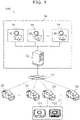
- FIG. 1 is a diagram schematically illustrating a configuration of a remote control system common to the present embodiment.
- a remote control system 100 is a system for remotely controlling autonomous driving vehicles 20 from a remote control center 30.
- the autonomous driving level of each autonomous driving vehicle 20 may be Level 4 or Level 5.
- the autonomous driving vehicle 20 is hereinafter referred to simply as “vehicle 20".
- the vehicle 20 includes an autonomous driving device 21.
- the autonomous driving device 21 includes a first electronic control unit (ECU) 211 that autonomously drives the vehicle, and a second ECU 212 that operates the vehicle 20 under remote control from the outside.
- the first ECU 211 for autonomous driving is hereinafter referred to as “autonomous driving ECU 211".
- the second ECU 212 for remote control is hereinafter referred to as "remote control ECU 212".
- the remote control in the present disclosure includes remote assistance and remote driving.
- the remote assistance and the remote driving are performed by a remote operator 36 based on a request from the vehicle 20 when the vehicle 20 has difficulty or is expected to have difficulty in continuing the autonomous driving.
- the remote operator 36 makes a part of determination for the autonomous driving of the vehicle 20. Basic calculations related to recognition, determination, and operation required for driving are performed in the vehicle 20.
- the remote operator 36 determines an action to be taken by the vehicle 20 based on information transmitted from the vehicle 20, and instructs the vehicle 20 to take the action.
- the remote assistance instruction to be sent from the remote operator 36 to the vehicle 20 includes an instruction to advance the vehicle 20 and an instruction to stop the vehicle 20.
- the remote assistance instruction may further include an instruction for offset avoidance of an obstacle ahead, an instruction to overtake a preceding vehicle, and an instruction for emergency evacuation.
- the remote operator 36 performs at least a part of the driving of the vehicle 20, specifically, a steering operation or an acceleration/deceleration operation.
- the recognition, determination, and operation required for driving are performed by the remote operator 36.
- the remote operator 36 drives the vehicle 20 from a remote place in the same manner as the driving at a driver's seat of the vehicle 20.
- the remote operator 36 need not always perform all the recognition, determination, and operation. At least a part of the recognition, determination, and operation may be assisted by functions of the vehicle 20.
- a server 32 and remote control terminals 34 are provided in the remote control center 30.
- the vehicles 20 are connected to the server 32 via a communication network 10 including 4th Generation (4G) and 5th Generation (5G).
- the number of vehicles 20 communicable with the server 32 is one or more, preferably plural.
- the server 32 receives a remote control request issued from any vehicle 20.
- the server 32 selects a remote operator 36 to respond to the remote control request based on details of the request (for example, a remote assistance request or a remote driving request).
- the remote control terminal 34 is an interface (human machine interface (HMI)) for the remote control by the remote operator 36.
- the remote control terminal 34 includes an information output unit that outputs, to the remote operator 36, information necessary for the remote control on the vehicle 20, and an operation input unit that inputs operations for the remote control by the remote operator 36.
- Examples of the information output unit include a display that outputs images captured by a camera of the vehicle 20, and a loudspeaker that outputs sounds collected by a microphone of the vehicle 20.
- Examples of an operation input unit for remote assistance include buttons, levers, and a touch panel.
- Examples of an operation input unit for remote driving include a steering wheel, an accelerator pedal, a brake pedal, an operation lever of a turn signal, and an operation lever of a wiper.
- Separate terminals or a common terminal may serve as the remote control terminal 34 for remote driving and the remote control terminal 34 for remote assistance.
- At least one remote control terminal 34 preferably a plurality of remote control terminals 34, is provided.
- remote operators 36 as many as the remote control terminals 34 are on standby.
- Each remote control terminal 34 is connected to the server 32 via a communication network including a local area network (LAN) and the Internet.
- the remote control center 30 need not be a real facility.
- the system in which the remote control terminals 34 are connected to the server 32 via the communication network is referred to as "remote control center 30". Therefore, the server 32 may be provided on a cloud, and the remote control terminals 34 may be provided at satellite offices in various places or homes of the remote operators 36.
- FIG. 2 is a diagram illustrating an outline of operations of the autonomous driving device 21.
- arrow lines represent statuses of control on the vehicle 20 by the autonomous driving device 21.
- a travel path of the vehicle 20 represented by a continuous arrow line indicates that the vehicle 20 is driven autonomously.
- a travel path of the vehicle 20 represented by a dotted arrow line indicates that the vehicle 20 is controlled remotely.
- the autonomous driving of the vehicle 20 is performed by the autonomous driving ECU 211.
- the autonomous driving ECU 211 is kept in an activated state during the autonomous driving. Since the remote control function of the remote control ECU 212 is not used during the autonomous driving, the remote control ECU 212 can be kept in a power saving state.
- the power saving state includes a state in which the power of the remote control ECU 212 is OFF, and a state in which the remote control ECU 212 is in a sleep state. As long as power saving can be realized, the power saving state may include a state in which an internal calculation module such as a central processing unit (CPU) or a graphics processing unit (GPU) that does not execute calculation is OFF.
- CPU central processing unit
- GPU graphics processing unit
- the remote control on the vehicle 20 is performed by the remote control ECU 212 in response to an instruction from the remote operator 36.
- the remote operator 36 and the remote control ECU 212 communicate with each other, and the remote control ECU 212 operates the vehicle 20 in response to an instruction received from the remote operator 36.
- the autonomous driving function of the autonomous driving ECU 211 is not used during the remote control, the autonomous driving ECU 211 may be brought into a power saving state as one idea to reduce power consumption.
- the autonomous driving ECU 211 is brought into the power saving state during the remote control, however, determination cannot be made as to whether the autonomous driving can be performed. Therefore, transition cannot be made from the remote control to the autonomous driving. This problem will be described in detail below.
- the following are examples of elements for the determination of whether the autonomous driving can be performed.
- this determination element includes the fact that the autonomous driving cannot be performed because a map is not prepared, and the fact that the autonomous driving cannot be performed because terrain and traffic rules may be changed due to construction work.
- this determination element includes the fact that sensors necessary for the autonomous driving do not operate due to dirt, the fact that a camera necessary for the autonomous driving cannot be used due to inappropriate brightness, and the fact that light detection and ranging (LiDAR) necessary for the autonomous driving cannot be used due to rain or fog.
- Specific examples of this determination element also include the fact that the self-position cannot be estimated because a global positioning system (GPS) receiver cannot receive a satellite signal.
- GPS global positioning system
- this determination element includes the fact that the autonomous driving cannot be performed due to damage, thermal runaway, and hang of hardware necessary for the autonomous driving, and the fact that the autonomous driving cannot be performed due to software abnormalities.
- a vehicle capable of fully autonomous driving at Level 5 may be adaptable to all situations. In an autonomous driving vehicle at Level 4 or lower and even the autonomous driving vehicle at Level 5, however, there is a possibility that determination cannot be made as to whether the autonomous driving can be performed unless calculations are actually performed on the spot.
- the elements for the determination of whether the autonomous driving can be performed include not only Element A by which the determination can uniquely be made based on an external factor, but also Element D by which the determination cannot be made unless the autonomous driving ECU 211 is actually operated.
- the autonomous driving ECU 211 controls the vehicle as continuously as possible in consideration of labor costs necessary for the remote control.
- the autonomous driving ECU 211 may call the remote control ECU 212 even if the remote control ECU 212 is in the power saving state. Therefore, transition can be made from the autonomous driving to the remote control even if the remote control ECU 212 is in the power saving state during the autonomous driving.
- the elements for the determination of whether the autonomous driving can be performed include not only Element A by which the determination can uniquely be made based on an external factor, but also Element D by which the determination cannot be made unless the autonomous driving ECU 211 is actually operated.
- Element A by which the determination can uniquely be made based on an external factor
- Element D by which the determination cannot be made unless the autonomous driving ECU 211 is actually operated.
- the remote operator 36 may switch the remote control to the autonomous driving, but the remote operator 36 does not know a timing when the autonomous driving ECU 211 can operate. Therefore, transition cannot be made to the autonomous driving, and the execution period of the remote control increases.
- the autonomous driving device 21 brings the remote control ECU 212 into the power saving state during the autonomous driving, and keeps the autonomous driving ECU 211 activated in parallel during the remote control. That is, the autonomous driving ECU 211 is operated continuously, and the remote control ECU 212 is operated only in response to a call from the autonomous driving ECU 211.
- the autonomous driving ECU 211 is operated continuously, and the remote control ECU 212 is operated only in response to a call from the autonomous driving ECU 211.
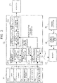
- FIG. 3 is a block diagram illustrating an example of a configuration of the autonomous driving device 21.
- a sensor unit 22 is connected to the autonomous driving device 21 by using an in-vehicle network such as a controller area network (CAN).
- the sensor unit 22 includes a LiDAR sensor 22a, a camera 22b, and a millimeter wave sensor 22c as recognition sensors for recognizing conditions around the vehicle 20.
- the camera 22b may be shared by the autonomous driving and the remote control, or different cameras may be provided for the autonomous driving and the remote control.
- the sensor unit 22 further includes a global positioning system (GPS) receiver 22d as a position sensor for detecting the position and orientation of the vehicle 20.
- the sensor unit 22 further includes an internal sensor 22e.
- the internal sensor 22e includes a condition sensor that acquires information about motion of the vehicle 20. Examples of the condition sensor include a wheel speed sensor, an acceleration sensor, an angular velocity sensor, and a steering angle sensor.
- An actuator 23 is connected to the autonomous driving device 21 by using the in-vehicle network such as the CAN.
- the actuator 23 includes a steering device for steering the vehicle 20, a driving device for driving the vehicle 20, and a braking device for braking the vehicle 20.
- Examples of the steering device include a power steering system, a steer-by-wire steering system, and a rear wheel steering system.
- Examples of the driving device include an engine, an EV system, and a hybrid system.
- Examples of the braking device include a hydraulic brake and a regenerative brake.
- the actuator 23 also includes devices such as a turn signal and a wiper that need to operate for safe traveling of the vehicle 20. The actuator 23 operates in response to a control signal transmitted from the autonomous driving device 21.
- the autonomous driving device 21 includes the autonomous driving ECU 211, the remote control ECU 212, and a vehicle control ECU 213 that is a third ECU.
- the ECUs 211, 212, and 213 are connected by using the in-vehicle network such as the CAN.
- Each of the ECUs 211, 212, and 213 includes a processor and a memory coupled to the processor.
- the memory stores one or more programs executable by the processor and various types of information related to the programs. When the processor executes the programs, various processes are realized by the processor.
- the memory includes a main storage device and an auxiliary storage device.
- the auxiliary storage device includes various databases including a map database.
- the autonomous driving ECU 211 includes an autonomous driving system unit 211a and a remote control function control unit 211b. These units are implemented as functions of the autonomous driving ECU 211 when the processor executes the programs stored in the memory of the autonomous driving ECU 211.
- the autonomous driving system unit 211a determines whether the autonomous driving can be performed based on various types of detection information from the sensor unit 22 and, if necessary, information acquired from various databases in the storage device. The elements for the determination are described above.
- the autonomous driving system unit 211a generates control information for autonomous driving (hereinafter referred to as "autonomous-driving control information").
- the autonomous driving system unit 211a transmits, to the remote control function control unit 211b, a signal associated with a result of the determination of whether the autonomous driving can be performed.
- a predetermined method can be used to generate the autonomous-driving control information.
- An example of the method will be described below.
- the position of the vehicle 20 on a map is recognized based on position information of the vehicle 20 that is received by the GPS receiver 22d, information about motion of the vehicle 20 that is detected by the internal sensor 22e, and map information acquired from the map database.
- Pieces of detection information are acquired from the LiDAR sensor 22a, the camera 22b, and the millimeter wave sensor 22c.
- Objects around the vehicle 20 are recognized by using a technique such as pattern matching or deep learning, and the positions and types of the objects are determined.
- the objects whose positions and types are determined are output as targets.
- a travel plan of the vehicle 20 is created based on a route and target information recorded in the map database. The travel plan is created so that the vehicle 20 travels appropriately on the route in light of references such as safety, legal compliance, and travel efficiency.
- the autonomous driving system unit 211a generates a target trajectory based on the created travel plan.
- the target trajectory includes a set of target positions of the vehicle 20 in a coordinate system fixed to the vehicle 20 and a target speed at each target point.
- the autonomous driving system unit 211a outputs the generated target trajectory as the autonomous-driving control information.
- the autonomous driving system unit 211a may calculate an actuator control amount (for example, a steering angle and a pedal depression amount) for causing the vehicle 20 to travel along the target trajectory, and output the actuator control amount as the autonomous-driving control information.
- a space where the vehicle 20 is allowed to travel may be created based on the travel plan, and the space may be output as the autonomous-driving control information.
- an ON/OFF operation of the turn signal may be included in the autonomous-driving control information.
- the remote control function control unit 211b transmits an activation signal or a stop signal to the remote control ECU 212 based on a signal from the autonomous driving system unit 211a. Specifically, when the autonomous driving can be performed, the remote control function control unit 211b transmits the stop signal to the remote control ECU 212 to bring the remote control ECU 212 into the power saving state. When the autonomous driving cannot be performed, the remote control function control unit 211b transmits the activation signal to the remote control ECU 212 to activate the remote control ECU 212.
- the remote control ECU 212 includes a remote control system unit 212a.
- the remote control system unit 212a is implemented as a function of the remote control ECU 212 when the processor executes the programs stored in the memory of the remote control ECU 212.
- the programs stored in the memory of the remote control ECU 212 constitute a program set for causing the autonomous driving device 21 to exert functions together with the programs stored in the memory of the autonomous driving ECU 211.
- the remote control system unit 212a communicates with the server 32, and transmits information necessary for the remote control to the server 32.
- the information transmitted to the server 32 includes various types of detection information from the sensor unit 22, including an image acquired by the camera 22b, and information acquired from various databases in the storage device if necessary.
- the information acquired from the outside of the remote control system 100 such as road traffic information acquired from a road traffic information system, is useful for the remote control, the information may be included in the transmission information.
- the information transmitted from the remote control system unit 212a to the server 32 is processed by the server 32 and transmitted to the remote control terminal 34.
- the remote control system unit 212a communicates with the server 32, and receives a remote control signal for the remote control from the server 32.
- the remote control signal is input to the remote control terminal 34 by the remote operator 36.
- the remote control signal is, for example, a remote driving signal generated through a steering operation or a pedaling operation.
- the remote control signal is, for example, a remote assistance signal generated through an operation on a button or lever.
- the remote control system unit 212a generates control information for remote control (hereinafter referred to as "remote-control control information") based on the remote control signal received from the server 32.
- the remote-control control information may be any information as long as the vehicle 20 can be controlled.
- the actuator control amount may be generated as the remote-control control information.
- an hourly control amount may be generated as the remote-control control information.
- a future control amount expected from a current control amount may be added to the hourly control amount. For example, information on the space where the vehicle 20 is allowed to travel may be added.
- the function for securing the robustness against the interruption or delay in communication may be provided to the vehicle control ECU 213 described later.
- the vehicle control ECU 213 includes a control information arbitration unit 213a and an actuator control unit 213b. These units are implemented as functions of the vehicle control ECU 213 when the processor executes the programs stored in the memory of the vehicle control ECU 213.
- the control information arbitration unit 213a arbitrates the autonomous-driving control information transmitted from the autonomous driving system unit 211a and the remote-control control information transmitted from the remote control system unit 212a.
- the following are examples of roles and methods of arbitration by the control information arbitration unit 213a.
- the remote control ECU 212 Since the remote control ECU 212 is activated or stopped depending on whether the autonomous driving can be performed, only one piece of control information is input essentially. In a system where time synchronization is not guaranteed, however, the two pieces of control information may be input. When the autonomous driving can be performed, only the autonomous-driving control information is adopted and the remote-control control information is rejected. As a result, time synchronization is guaranteed by the control information arbitration unit 213a.
- Arbitration Method 2 Method of Adopting Only One Piece of Control Information and Smoothly Switching Control Information in Transition
- the behavior of the vehicle 20 may become unstable at the time of switching, which may cause discomfort to occupants.
- an instruction to depress the accelerator pedal is given in the autonomous driving and an instruction to release the accelerator pedal is given in the remote control
- sudden deceleration occurs in the transition from the autonomous driving to the remote control
- sudden acceleration occurs in the transition from the remote control to the autonomous driving. Therefore, calculation is performed to smoothly switch the control information in these transitions.
- the control information arbitrated by the control information arbitration unit 213a is transmitted to the actuator control unit 213b in a subsequent stage.
- the actuator control unit 213b calculates the actuator control amount of the actuator 23 based on the control information transmitted from the control information arbitration unit 213a. Then, the actuator control unit 213b controls the actuator 23 by the actuator control amount.
- the description "smoothly switching control information" in Arbitration Method 2 means generation of such control information that the actuator control amount changes smoothly.
- FIG. 4 is a flowchart illustrating the autonomous driving method by the autonomous driving device 21.
- processing entities are illustrated together with details of processes of individual steps.
- the flowchart starts in a state in which the autonomous driving ECU 211 is performing the autonomous driving.
- Step S1 the control by the autonomous driving ECU 211, that is, the autonomous driving is being performed.
- the entity of this process is the autonomous driving system unit 211a.
- Step S2 the autonomous driving system unit 211a determines whether the autonomous driving ECU 211 can operate continuously. In this determination, Determination Elements A to D are taken into consideration. When determination is made that the operation can be continued, the process returns to Step S1 and the control by the autonomous driving ECU 211 is continued.
- Step S2 When determination is made in Step S2 that the operation cannot be continued, the remote control function control unit 211b performs a process of Step S3.
- Step S3 the remote control ECU 212 is activated by the remote control function control unit 211b.
- Step S4 the control by the remote control ECU 212, that is, the remote control is performed.
- the entity of this process is the remote control system unit 212a.
- Step S5 the autonomous driving system unit 211a determines whether the autonomous driving ECU 211 can operate. In this determination, Determination Elements A to D are taken into consideration. When determination is made that the operation is not possible, the process returns to Step S4 and the control by the remote control ECU 212 is continued.
- Step S6 the autonomous driving system unit 211a starts the control by the autonomous driving ECU 211.
- Step S7 the remote control ECU 212 is brought into a power saving mode by the remote control function control unit 211b.
- FIGS. 5 and 6 are sequence diagrams illustrating the autonomous driving method described above.
- FIG. 5 is a sequence diagram illustrating operations of the autonomous driving ECU 211 and the remote control ECU 212 in the transition from the autonomous driving to the remote control.
- a power saving termination instruction that is, an activation instruction is transmitted from the autonomous driving ECU 211 to the remote control ECU 212.
- the remote control ECU 212 makes transition from the power saving state to the activated state in response to the power saving termination instruction from the autonomous driving ECU 211.
- the remote control ECU 212 notifies the autonomous driving ECU 211 that the remote control ECU 212 has been activated.
- FIG. 6 is a sequence diagram illustrating operations of the autonomous driving ECU 211 and the remote control ECU 212 in the transition from the remote control to the autonomous driving.
- a power saving instruction that is, a stop instruction is transmitted from the autonomous driving ECU 211 to the remote control ECU 212.
- the remote control ECU 212 makes transition from the activated state to the power saving state in response to the power saving instruction from the autonomous driving ECU 211.
- a response signal is transmitted from the remote control ECU 212 to the autonomous driving ECU 211.
- the determination of whether the autonomous driving can be performed is made based on Determination Elements A to D. These are elements by which determination is made as to whether the calculation for the autonomous driving is possible, but some constraints may be imposed on the transition conditions from the autonomous driving to the remote control. The following are examples of constraints in the transition.
- the autonomous driving system unit 211a determines whether the autonomous driving can be performed, pieces of information on Constraints 1 to 3 may be used in addition to Determination Elements A to D.
- the autonomous driving system unit 211a determines whether the autonomous driving can be performed, and generates the autonomous-driving control information when the autonomous driving can be performed. These two functions may be provided separately. That is, an autonomous driving executability determination unit, an autonomous-driving control information generation unit, and the remote control function control unit may be provided as the functions of the autonomous driving ECU 211.
- the remote control ECU 212 in the embodiment described above may be provided as a set of a remote assistance ECU for the remote assistance and a remote driving ECU for the remote driving.
- a remote assistance ECU for the remote assistance
- a remote driving ECU for the remote driving.
Landscapes
- Engineering & Computer Science (AREA)
- Automation & Control Theory (AREA)
- Mechanical Engineering (AREA)
- Transportation (AREA)
- Physics & Mathematics (AREA)
- General Physics & Mathematics (AREA)
- Human Computer Interaction (AREA)
- Theoretical Computer Science (AREA)
- General Engineering & Computer Science (AREA)
- Aviation & Aerospace Engineering (AREA)
- Radar, Positioning & Navigation (AREA)
- Remote Sensing (AREA)
- Computing Systems (AREA)
- Computer Hardware Design (AREA)
- Traffic Control Systems (AREA)
- Control Of Driving Devices And Active Controlling Of Vehicle (AREA)
Applications Claiming Priority (1)
| Application Number | Priority Date | Filing Date | Title |
|---|---|---|---|
| JP2021044990A JP7347465B2 (ja) | 2021-03-18 | 2021-03-18 | 自動運転装置、自動運転方法、及びプログラムセット |
Publications (3)
| Publication Number | Publication Date |
|---|---|
| EP4060444A1 true EP4060444A1 (fr) | 2022-09-21 |
| EP4060444C0 EP4060444C0 (fr) | 2025-12-10 |
| EP4060444B1 EP4060444B1 (fr) | 2025-12-10 |
Family
ID=80683133
Family Applications (1)
| Application Number | Title | Priority Date | Filing Date |
|---|---|---|---|
| EP22160426.7A Active EP4060444B1 (fr) | 2021-03-18 | 2022-03-07 | Dispositif d'entraînement autonome, procédé d'entraînement autonome et pluralité de supports de stockage non transitoires |
Country Status (4)
| Country | Link |
|---|---|
| US (1) | US12103565B2 (fr) |
| EP (1) | EP4060444B1 (fr) |
| JP (1) | JP7347465B2 (fr) |
| CN (1) | CN115107790A (fr) |
Families Citing this family (3)
| Publication number | Priority date | Publication date | Assignee | Title |
|---|---|---|---|---|
| JP7367723B2 (ja) * | 2021-03-30 | 2023-10-24 | トヨタ自動車株式会社 | 自動運転装置、自動運転方法、及びプログラム |
| WO2025147592A1 (fr) * | 2024-01-04 | 2025-07-10 | Textron Systems Corporation | Commutation de procédé de commande de mobilité de robot terrestre |
| WO2025179107A1 (fr) * | 2024-02-21 | 2025-08-28 | Textron Systems Corporation | Communication entre un ordinateur de commande et un robot terrestre |
Citations (5)
| Publication number | Priority date | Publication date | Assignee | Title |
|---|---|---|---|---|
| US20160340867A1 (en) * | 2015-03-11 | 2016-11-24 | Kubota Corporation | Work Vehicle and Running Control Apparatus Causing Automatic Running of Work Vehicle |
| JP2018077649A (ja) | 2016-11-09 | 2018-05-17 | 本田技研工業株式会社 | 遠隔運転制御装置、車両制御システム、遠隔運転制御方法、および遠隔運転制御プログラム |
| US20190066399A1 (en) * | 2017-08-28 | 2019-02-28 | GM Global Technology Operations LLC | Controller architecture for monitoring health of an autonomous vehicle |
| US20200047773A1 (en) * | 2016-11-09 | 2020-02-13 | Honda Motor Co., Ltd. | Vehicle control device, vehicle control system, vehicle control method, and vehicle control program |
| WO2020202380A1 (fr) * | 2019-03-29 | 2020-10-08 | 本田技研工業株式会社 | Dispositif de commande, procédé de commande et programme |
Family Cites Families (9)
| Publication number | Priority date | Publication date | Assignee | Title |
|---|---|---|---|---|
| JP2000311299A (ja) | 1999-04-28 | 2000-11-07 | Honda Motor Co Ltd | 自動追従走行システムの隊列形成方法 |
| KR100914904B1 (ko) * | 2009-03-13 | 2009-08-31 | 국방과학연구소 | 무인주행기계, 무인주행시스템 및 무인주행기계의 제어방법 |
| JP6310565B2 (ja) | 2014-09-11 | 2018-04-11 | 本田技研工業株式会社 | 運転支援装置 |
| WO2019046204A1 (fr) * | 2017-08-28 | 2019-03-07 | nuTonomy Inc. | Conduite en mode mixte d'un véhicule ayant des capacités de conduite autonome |
| US20200057441A1 (en) * | 2018-08-14 | 2020-02-20 | May Mobility, Inc. | Systems and methods for intelligent arbitration between autonomous and manual operation signals of an autonomous agent |
| JP7098552B2 (ja) | 2019-02-06 | 2022-07-11 | Kddi株式会社 | 遠隔運転制御システム、車両、コンピュータプログラム及び遠隔運転制御方法 |
| US10717448B1 (en) * | 2019-04-30 | 2020-07-21 | Atlas Robotics, Inc. | Automated transfer of vehicle control for autonomous driving |
| JP7322536B2 (ja) * | 2019-06-14 | 2023-08-08 | マツダ株式会社 | 移動体の制御装置 |
| JP2021022319A (ja) * | 2019-07-30 | 2021-02-18 | トヨタ自動車株式会社 | 車両走行制御装置 |
-
2021
- 2021-03-18 JP JP2021044990A patent/JP7347465B2/ja active Active
-
2022
- 2022-03-07 EP EP22160426.7A patent/EP4060444B1/fr active Active
- 2022-03-15 CN CN202210254556.8A patent/CN115107790A/zh active Pending
- 2022-03-16 US US17/696,202 patent/US12103565B2/en active Active
Patent Citations (5)
| Publication number | Priority date | Publication date | Assignee | Title |
|---|---|---|---|---|
| US20160340867A1 (en) * | 2015-03-11 | 2016-11-24 | Kubota Corporation | Work Vehicle and Running Control Apparatus Causing Automatic Running of Work Vehicle |
| JP2018077649A (ja) | 2016-11-09 | 2018-05-17 | 本田技研工業株式会社 | 遠隔運転制御装置、車両制御システム、遠隔運転制御方法、および遠隔運転制御プログラム |
| US20200047773A1 (en) * | 2016-11-09 | 2020-02-13 | Honda Motor Co., Ltd. | Vehicle control device, vehicle control system, vehicle control method, and vehicle control program |
| US20190066399A1 (en) * | 2017-08-28 | 2019-02-28 | GM Global Technology Operations LLC | Controller architecture for monitoring health of an autonomous vehicle |
| WO2020202380A1 (fr) * | 2019-03-29 | 2020-10-08 | 本田技研工業株式会社 | Dispositif de commande, procédé de commande et programme |
Also Published As
| Publication number | Publication date |
|---|---|
| EP4060444C0 (fr) | 2025-12-10 |
| JP2022144117A (ja) | 2022-10-03 |
| US20220297722A1 (en) | 2022-09-22 |
| CN115107790A (zh) | 2022-09-27 |
| JP7347465B2 (ja) | 2023-09-20 |
| US12103565B2 (en) | 2024-10-01 |
| EP4060444B1 (fr) | 2025-12-10 |
Similar Documents
| Publication | Publication Date | Title |
|---|---|---|
| US11708091B2 (en) | Vehicle traveling control system and vehicle control system | |
| EP4060444B1 (fr) | Dispositif d'entraînement autonome, procédé d'entraînement autonome et pluralité de supports de stockage non transitoires | |
| JP7620770B2 (ja) | 車両センサデータの分散処理 | |
| US12060086B2 (en) | Autonomous driving device, autonomous driving method, and non-transitory storage medium | |
| EP3915857B1 (fr) | Appareil d'assistance au stationnement et procédé de commande de l'appareil d'assistance au stationnement | |
| US11285943B2 (en) | Vehicle control system and control method | |
| CN109229102A (zh) | 无人驾驶车辆控制系统、方法和装置 | |
| CN109844840B (zh) | 车辆控制装置 | |
| CN110171421B (zh) | 车辆控制装置 | |
| US11524694B2 (en) | Vehicle control apparatus, vehicle, vehicle control method, and non-transitory computer-readable storage medium | |
| US11634129B2 (en) | Travel control apparatus, vehicle, travel control method, and non-transitory computer-readable storage medium | |
| CN113525373A (zh) | 一种车辆的变道控制系统、控制方法 | |
| US11643091B2 (en) | In-vehicle equipment control device | |
| US20220397898A1 (en) | Remote control request system, remote control request method, and nontransitory storage medium | |
| CN112009480A (zh) | 驾驶辅助系统 | |
| WO2022144954A1 (fr) | Dispositif de commande de véhicule, procédé de commande de véhicule et programme | |
| CN115996870A (zh) | 车辆控制装置、车辆控制方法及程序 | |
| CN115042803B (zh) | 利用驾驶员作为传感器以最小化自动驾驶脱离的驾驶员辅助自动驾驶系统 | |
| CN115314670B (zh) | 远程监视装置、远程监视系统以及远程监视方法 | |
| US20230061405A1 (en) | Autonomous driving system, path plan generation method, and storage medium | |
| CN115771469A (zh) | 运算装置 | |
| CN115503713A (zh) | 远程驾驶车辆、远程驾驶系统以及蛇行驾驶抑制方法 | |
| US20240185652A1 (en) | Information processing device, vehicle, and information processing system | |
| US20250010889A1 (en) | Storage medium | |
| US20260097790A1 (en) | Control apparatus of vehicle |
Legal Events
| Date | Code | Title | Description |
|---|---|---|---|
| PUAI | Public reference made under article 153(3) epc to a published international application that has entered the european phase |
Free format text: ORIGINAL CODE: 0009012 |
|
| STAA | Information on the status of an ep patent application or granted ep patent |
Free format text: STATUS: REQUEST FOR EXAMINATION WAS MADE |
|
| 17P | Request for examination filed |
Effective date: 20220307 |
|
| AK | Designated contracting states |
Kind code of ref document: A1 Designated state(s): AL AT BE BG CH CY CZ DE DK EE ES FI FR GB GR HR HU IE IS IT LI LT LU LV MC MK MT NL NO PL PT RO RS SE SI SK SM TR |
|
| STAA | Information on the status of an ep patent application or granted ep patent |
Free format text: STATUS: EXAMINATION IS IN PROGRESS |
|
| 17Q | First examination report despatched |
Effective date: 20230629 |
|
| GRAP | Despatch of communication of intention to grant a patent |
Free format text: ORIGINAL CODE: EPIDOSNIGR1 |
|
| STAA | Information on the status of an ep patent application or granted ep patent |
Free format text: STATUS: GRANT OF PATENT IS INTENDED |
|
| INTG | Intention to grant announced |
Effective date: 20250725 |
|
| GRAS | Grant fee paid |
Free format text: ORIGINAL CODE: EPIDOSNIGR3 |
|
| GRAA | (expected) grant |
Free format text: ORIGINAL CODE: 0009210 |
|
| STAA | Information on the status of an ep patent application or granted ep patent |
Free format text: STATUS: THE PATENT HAS BEEN GRANTED |
|
| AK | Designated contracting states |
Kind code of ref document: B1 Designated state(s): AL AT BE BG CH CY CZ DE DK EE ES FI FR GB GR HR HU IE IS IT LI LT LU LV MC MK MT NL NO PL PT RO RS SE SI SK SM TR |
|
| REG | Reference to a national code |
Ref country code: CH Ref legal event code: F10 Free format text: ST27 STATUS EVENT CODE: U-0-0-F10-F00 (AS PROVIDED BY THE NATIONAL OFFICE) Effective date: 20251210 Ref country code: GB Ref legal event code: FG4D |
|
| REG | Reference to a national code |
Ref country code: DE Ref legal event code: R096 Ref document number: 602022026406 Country of ref document: DE |
|
| REG | Reference to a national code |
Ref country code: IE Ref legal event code: FG4D |
|
| U01 | Request for unitary effect filed |
Effective date: 20260105 |
|
| U07 | Unitary effect registered |
Designated state(s): AT BE BG DE DK EE FI FR IT LT LU LV MT NL PT RO SE SI Effective date: 20260113 |
|
| U20 | Renewal fee for the european patent with unitary effect paid |
Year of fee payment: 5 Effective date: 20260218 |
|
| PG25 | Lapsed in a contracting state [announced via postgrant information from national office to epo] |
Ref country code: ES Free format text: LAPSE BECAUSE OF FAILURE TO SUBMIT A TRANSLATION OF THE DESCRIPTION OR TO PAY THE FEE WITHIN THE PRESCRIBED TIME-LIMIT Effective date: 20251210 |
|
| PG25 | Lapsed in a contracting state [announced via postgrant information from national office to epo] |
Ref country code: NO Free format text: LAPSE BECAUSE OF FAILURE TO SUBMIT A TRANSLATION OF THE DESCRIPTION OR TO PAY THE FEE WITHIN THE PRESCRIBED TIME-LIMIT Effective date: 20260310 |
|
| PG25 | Lapsed in a contracting state [announced via postgrant information from national office to epo] |
Ref country code: HR Free format text: LAPSE BECAUSE OF FAILURE TO SUBMIT A TRANSLATION OF THE DESCRIPTION OR TO PAY THE FEE WITHIN THE PRESCRIBED TIME-LIMIT Effective date: 20251210 |
|
| PG25 | Lapsed in a contracting state [announced via postgrant information from national office to epo] |
Ref country code: RS Free format text: LAPSE BECAUSE OF FAILURE TO SUBMIT A TRANSLATION OF THE DESCRIPTION OR TO PAY THE FEE WITHIN THE PRESCRIBED TIME-LIMIT Effective date: 20260310 |
|
| U1N | Appointed representative for the unitary patent procedure changed after the registration of the unitary effect |
Representative=s name: MARKS & CLERK LLP; GB |