EP4060976A1 - Elektronische vorrichtung mit kamera und verfahren dafür - Google Patents
Elektronische vorrichtung mit kamera und verfahren dafür Download PDFInfo
- Publication number
- EP4060976A1 EP4060976A1 EP20888008.8A EP20888008A EP4060976A1 EP 4060976 A1 EP4060976 A1 EP 4060976A1 EP 20888008 A EP20888008 A EP 20888008A EP 4060976 A1 EP4060976 A1 EP 4060976A1
- Authority
- EP
- European Patent Office
- Prior art keywords
- sensor
- distance
- electronic device
- processor
- target object
- Prior art date
- Legal status (The legal status is an assumption and is not a legal conclusion. Google has not performed a legal analysis and makes no representation as to the accuracy of the status listed.)
- Granted
Links
Images







Classifications
-
- H—ELECTRICITY
- H04—ELECTRIC COMMUNICATION TECHNIQUE
- H04N—PICTORIAL COMMUNICATION, e.g. TELEVISION
- H04N23/00—Cameras or camera modules comprising electronic image sensors; Control thereof
- H04N23/45—Cameras or camera modules comprising electronic image sensors; Control thereof for generating image signals from two or more image sensors being of different type or operating in different modes, e.g. with a CMOS sensor for moving images in combination with a charge-coupled device [CCD] for still images
-
- G—PHYSICS
- G01—MEASURING; TESTING
- G01S—RADIO DIRECTION-FINDING; RADIO NAVIGATION; DETERMINING DISTANCE OR VELOCITY BY USE OF RADIO WAVES; LOCATING OR PRESENCE-DETECTING BY USE OF THE REFLECTION OR RERADIATION OF RADIO WAVES; ANALOGOUS ARRANGEMENTS USING OTHER WAVES
- G01S17/00—Systems using the reflection or reradiation of electromagnetic waves other than radio waves, e.g. lidar systems
- G01S17/86—Combinations of lidar systems with systems other than lidar, radar or sonar, e.g. with direction finders
-
- G—PHYSICS
- G01—MEASURING; TESTING
- G01S—RADIO DIRECTION-FINDING; RADIO NAVIGATION; DETERMINING DISTANCE OR VELOCITY BY USE OF RADIO WAVES; LOCATING OR PRESENCE-DETECTING BY USE OF THE REFLECTION OR RERADIATION OF RADIO WAVES; ANALOGOUS ARRANGEMENTS USING OTHER WAVES
- G01S17/00—Systems using the reflection or reradiation of electromagnetic waves other than radio waves, e.g. lidar systems
- G01S17/88—Lidar systems specially adapted for specific applications
-
- G—PHYSICS
- G01—MEASURING; TESTING
- G01S—RADIO DIRECTION-FINDING; RADIO NAVIGATION; DETERMINING DISTANCE OR VELOCITY BY USE OF RADIO WAVES; LOCATING OR PRESENCE-DETECTING BY USE OF THE REFLECTION OR RERADIATION OF RADIO WAVES; ANALOGOUS ARRANGEMENTS USING OTHER WAVES
- G01S17/00—Systems using the reflection or reradiation of electromagnetic waves other than radio waves, e.g. lidar systems
- G01S17/88—Lidar systems specially adapted for specific applications
- G01S17/89—Lidar systems specially adapted for specific applications for mapping or imaging
-
- G—PHYSICS
- G01—MEASURING; TESTING
- G01S—RADIO DIRECTION-FINDING; RADIO NAVIGATION; DETERMINING DISTANCE OR VELOCITY BY USE OF RADIO WAVES; LOCATING OR PRESENCE-DETECTING BY USE OF THE REFLECTION OR RERADIATION OF RADIO WAVES; ANALOGOUS ARRANGEMENTS USING OTHER WAVES
- G01S7/00—Details of systems according to groups G01S13/00, G01S15/00, G01S17/00
- G01S7/48—Details of systems according to groups G01S13/00, G01S15/00, G01S17/00 of systems according to group G01S17/00
- G01S7/497—Means for monitoring or calibrating
-
- H—ELECTRICITY
- H04—ELECTRIC COMMUNICATION TECHNIQUE
- H04N—PICTORIAL COMMUNICATION, e.g. TELEVISION
- H04N23/00—Cameras or camera modules comprising electronic image sensors; Control thereof
- H04N23/60—Control of cameras or camera modules
- H04N23/61—Control of cameras or camera modules based on recognised objects
-
- H—ELECTRICITY
- H04—ELECTRIC COMMUNICATION TECHNIQUE
- H04N—PICTORIAL COMMUNICATION, e.g. TELEVISION
- H04N23/00—Cameras or camera modules comprising electronic image sensors; Control thereof
- H04N23/60—Control of cameras or camera modules
- H04N23/62—Control of parameters via user interfaces
-
- H—ELECTRICITY
- H04—ELECTRIC COMMUNICATION TECHNIQUE
- H04N—PICTORIAL COMMUNICATION, e.g. TELEVISION
- H04N23/00—Cameras or camera modules comprising electronic image sensors; Control thereof
- H04N23/60—Control of cameras or camera modules
- H04N23/63—Control of cameras or camera modules by using electronic viewfinders
- H04N23/633—Control of cameras or camera modules by using electronic viewfinders for displaying additional information relating to control or operation of the camera
- H04N23/634—Warning indications
-
- H—ELECTRICITY
- H04—ELECTRIC COMMUNICATION TECHNIQUE
- H04N—PICTORIAL COMMUNICATION, e.g. TELEVISION
- H04N23/00—Cameras or camera modules comprising electronic image sensors; Control thereof
- H04N23/60—Control of cameras or camera modules
- H04N23/64—Computer-aided capture of images, e.g. transfer from script file into camera, check of taken image quality, advice or proposal for image composition or decision on when to take image
-
- H—ELECTRICITY
- H04—ELECTRIC COMMUNICATION TECHNIQUE
- H04N—PICTORIAL COMMUNICATION, e.g. TELEVISION
- H04N23/00—Cameras or camera modules comprising electronic image sensors; Control thereof
- H04N23/60—Control of cameras or camera modules
- H04N23/65—Control of camera operation in relation to power supply
-
- H—ELECTRICITY
- H04—ELECTRIC COMMUNICATION TECHNIQUE
- H04N—PICTORIAL COMMUNICATION, e.g. TELEVISION
- H04N23/00—Cameras or camera modules comprising electronic image sensors; Control thereof
- H04N23/60—Control of cameras or camera modules
- H04N23/667—Camera operation mode switching, e.g. between still and video, sport and normal or high- and low-resolution modes
-
- H—ELECTRICITY
- H04—ELECTRIC COMMUNICATION TECHNIQUE
- H04N—PICTORIAL COMMUNICATION, e.g. TELEVISION
- H04N23/00—Cameras or camera modules comprising electronic image sensors; Control thereof
- H04N23/60—Control of cameras or camera modules
- H04N23/67—Focus control based on electronic image sensor signals
-
- H—ELECTRICITY
- H04—ELECTRIC COMMUNICATION TECHNIQUE
- H04N—PICTORIAL COMMUNICATION, e.g. TELEVISION
- H04N23/00—Cameras or camera modules comprising electronic image sensors; Control thereof
- H04N23/60—Control of cameras or camera modules
- H04N23/67—Focus control based on electronic image sensor signals
- H04N23/671—Focus control based on electronic image sensor signals in combination with active ranging signals, e.g. using light or sound signals emitted toward objects
-
- H—ELECTRICITY
- H04—ELECTRIC COMMUNICATION TECHNIQUE
- H04N—PICTORIAL COMMUNICATION, e.g. TELEVISION
- H04N23/00—Cameras or camera modules comprising electronic image sensors; Control thereof
- H04N23/95—Computational photography systems, e.g. light-field imaging systems
- H04N23/958—Computational photography systems, e.g. light-field imaging systems for extended depth of field imaging
- H04N23/959—Computational photography systems, e.g. light-field imaging systems for extended depth of field imaging by adjusting depth of field during image capture, e.g. maximising or setting range based on scene characteristics
-
- H—ELECTRICITY
- H04—ELECTRIC COMMUNICATION TECHNIQUE
- H04N—PICTORIAL COMMUNICATION, e.g. TELEVISION
- H04N23/00—Cameras or camera modules comprising electronic image sensors; Control thereof
- H04N23/70—Circuitry for compensating brightness variation in the scene
- H04N23/73—Circuitry for compensating brightness variation in the scene by influencing the exposure time
Definitions
- Various embodiments of the disclosure relate to an electronic device including a camera, and an operating method thereof.
- an electronic device may enhance user's convenience by utilizing depth information according to distances between the electronic device and target objects (for example, a subject, an external object, etc.).
- An electronic device may include a time of flight (ToF) module to acquire distance information on a target object.
- ToF time of flight
- a distance that can be measured by using ToF.
- a result of measurement may guarantee accuracy to some extent with respect to a target object existing within a predetermined distance, but, with respect to a target object getting out of the predetermined distance, it may be impossible to measure a distance or a measurement value of a great error may be derived.
- the electronic device may consume power while continuously performing the ToF function although accuracy is not guaranteed, and user satisfaction may be degraded.
- an electronic device includes: a first sensor configured to acquire an image including at least one target object; a second sensor configured to generate depth data regarding the at least one target object; at least one processor operatively connected with the first sensor and the second sensor; and at least one memory operatively connected with the processor, wherein the memory stores instructions that, when being executed, cause the processor to: while acquiring the image by using the first sensor, calculate a first distance between the at least one target object and the electronic device, based on the depth data generated by using the second sensor; stop an operation of the second sensor when the calculated first distance is longer than a designated distance; while the operation of the second sensor is stopped, calculate a second distance between the at least one target object and the electronic device, by using the first sensor; and, when the calculated second distance is within the designated distance, resume the operation of the second sensor.
- an operating method of an electronic device includes: while acquiring an image including at least one target object by using a first sensor, generating depth data on the at least one target object by using a second sensor; calculating a first distance between the at least one target object and the electronic device, based on the depth data; stopping an operation of the second sensor when the calculated first distance is longer than a designated distance; while the operation of the second sensor is stopped, calculating a second distance between the at least one target object and the electronic device, by using the first sensor; and, when the calculated second distance is within the designated distance, resuming the operation of the second sensor.
- the electronic device may determine whether a target object gets out of a designated threshold distance while acquiring distance information on the target object, and may at least temporarily stop an operation of a sensor for acquiring distance information based on the determination, so that power consumption of the electronic device may be reduced.
- the electronic device may enhance accuracy of distance information by changing a measurement parameter for acquiring distance information, while a target object is getting out of a designated threshold distance.
- Fig. 1 is a block diagram illustrating an electronic device 101 in a network environment 100 according to various embodiments.
- the electronic device 101 in the network environment 100 may communicate with an electronic device 102 via a first network 198 (e.g., a short-range wireless communication network), or an electronic device 104 or a server 108 via a second network 199 (e.g., a long-range wireless communication network).
- the electronic device 101 may communicate with the electronic device 104 via the server 108.
- the electronic device 101 may include a processor 120, memory 130, an input device 150, a sound output device 155, a display device 160, an audio module 170, a sensor module 176, an interface 177, a haptic module 179, a camera module 180, a power management module 188, a battery 189, a communication module 190, a subscriber identification module(SIM) 196, or an antenna module 197.
- at least one (e.g., the display device 160 or the camera module 180) of the components may be omitted from the electronic device 101, or one or more other components may be added in the electronic device 101.
- some of the components may be implemented as single integrated circuitry.
- the sensor module 176 e.g., a fingerprint sensor, an iris sensor, or an illuminance sensor
- the display device 160 e.g., a display
- an haptic module 179 e.g., a camera module 180
- a power management module 188 e.g., the display
- the processor 120 may execute, for example, software (e.g., a program 140) to control at least one other component (e.g., a hardware or software component) of the electronic device 101 coupled with the processor 120, and may perform various data processing or computation. According to one embodiment, as at least part of the data processing or computation, the processor 120 may load a command or data received from another component (e.g., the sensor module 176 or the communication module 190) in volatile memory 132, process the command or the data stored in the volatile memory 132, and store resulting data in non-volatile memory 134.
- software e.g., a program 140
- the processor 120 may load a command or data received from another component (e.g., the sensor module 176 or the communication module 190) in volatile memory 132, process the command or the data stored in the volatile memory 132, and store resulting data in non-volatile memory 134.
- the processor 120 may include a main processor 121 (e.g., a central processing unit (CPU) or an application processor (AP)), and an auxiliary processor 123 (e.g., a graphics processing unit (GPU), an image signal processor (ISP), a sensor hub processor, or a communication processor (CP)) that is operable independently from, or in conjunction with, the main processor 121.
- auxiliary processor 123 may be adapted to consume less power than the main processor 121, or to be specific to a specified function.
- the auxiliary processor 123 may be implemented as separate from, or as part of the main processor 121.
- the auxiliary processor 123 may control at least some of functions or states related to at least one component (e.g., the display device 160, the sensor module 176, or the communication module 190) among the components of the electronic device 101, instead of the main processor 121 while the main processor 121 is in an inactive (e.g., sleep) state, or together with the main processor 121 while the main processor 121 is in an active state (e.g., executing an application).
- the auxiliary processor 123 e.g., an image signal processor or a communication processor
- the memory 130 may store various data used by at least one component (e.g., the processor 120 or the sensor module 176) of the electronic device 101.
- the various data may include, for example, software (e.g., the program 140) and input data or output data for a command related thererto.
- the memory 130 may include the volatile memory 132 or the non-volatile memory 134.
- the program 140 may be stored in the memory 130 as software, and may include, for example, an operating system (OS) 142, middleware 144, or an application 146.
- OS operating system
- middleware middleware
- application application
- the input device 150 may receive a command or data to be used by other component (e.g., the processor 120) of the electronic device 101, from the outside (e.g., a user) of the electronic device 101.
- the input device 150 may include, for example, a microphone, a mouse, a keyboard, or a digital pen (e.g., a stylus pen).
- the sound output device 155 may output sound signals to the outside of the electronic device 101.
- the sound output device 155 may include, for example, a speaker or a receiver.
- the speaker may be used for general purposes, such as playing multimedia or playing record, and the receiver may be used for an incoming calls. According to an embodiment, the receiver may be implemented as separate from, or as part of the speaker.
- the display device 160 may visually provide information to the outside (e.g., a user) of the electronic device 101.
- the display device 160 may include, for example, a display, a hologram device, or a projector and control circuitry to control a corresponding one of the display, hologram device, and projector.
- the display device 160 may include touch circuitry adapted to detect a touch, or sensor circuitry (e.g., a pressure sensor) adapted to measure the intensity of force incurred by the touch.
- the audio module 170 may convert a sound into an electrical signal and vice versa. According to an embodiment, the audio module 170 may obtain the sound via the input device 150, or output the sound via the sound output device 155 or a headphone of an external electronic device (e.g., an electronic device 102) directly (e.g., wiredly) or wirelessly coupled with the electronic device 101.
- an external electronic device e.g., an electronic device 102
- directly e.g., wiredly
- wirelessly e.g., wirelessly
- the sensor module 176 may detect an operational state (e.g., power or temperature) of the electronic device 101 or an environmental state (e.g., a state of a user) external to the electronic device 101, and then generate an electrical signal or data value corresponding to the detected state.
- the sensor module 176 may include, for example, a gesture sensor, a gyro sensor, an atmospheric pressure sensor, a magnetic sensor, an acceleration sensor, a grip sensor, a proximity sensor, a color sensor, an infrared (IR) sensor, a biometric sensor, a temperature sensor, a humidity sensor, or an illuminance sensor.
- the interface 177 may support one or more specified protocols to be used for the electronic device 101 to be coupled with the external electronic device (e.g., the electronic device 102) directly (e.g., wiredly) or wirelessly.
- the interface 177 may include, for example, a high definition multimedia interface (HDMI), a universal serial bus (USB) interface, a secure digital (SD) card interface, or an audio interface.
- HDMI high definition multimedia interface
- USB universal serial bus
- SD secure digital
- a connecting terminal 178 may include a connector via which the electronic device 101 may be physically connected with the external electronic device (e.g., the electronic device 102).
- the connecting terminal 178 may include, for example, a HDMI connector, a USB connector, a SD card connector, or an audio connector (e.g., a headphone connector).
- the haptic module 179 may convert an electrical signal into a mechanical stimulus (e.g., a vibration or a movement) or electrical stimulus which may be recognized by a user via his tactile sensation or kinesthetic sensation.
- the haptic module 179 may include, for example, a motor, a piezoelectric element, or an electric stimulator.
- the camera module 180 may capture a still image or moving images.
- the camera module 180 may include one or more lenses, image sensors, image signal processors, or flashes.
- the power management module 188 may manage power supplied to the electronic device 101.
- the power management module 188 may be implemented as at least part of, for example, a power management integrated circuit (PMIC).
- PMIC power management integrated circuit
- the battery 189 may supply power to at least one component of the electronic device 101.
- the battery 189 may include, for example, a primary cell which is not rechargeable, a secondary cell which is rechargeable, or a fuel cell.
- the communication module 190 may support establishing a direct (e.g., wired) communication channel or a wireless communication channel between the electronic device 101 and the external electronic device (e.g., the electronic device 102, the electronic device 104, or the server 108) and performing communication via the established communication channel.
- the communication module 190 may include one or more communication processors that are operable independently from the processor 120 (e.g., the application processor (AP)) and supports a direct (e.g., wired) communication or a wireless communication.
- AP application processor
- the communication module 190 may include a wireless communication module 192 (e.g., a cellular communication module, a short-range wireless communication module, or a global navigation satellite system (GNSS) communication module) or a wired communication module 194 (e.g., a local area network (LAN) communication module or a power line communication (PLC) module).
- a wireless communication module 192 e.g., a cellular communication module, a short-range wireless communication module, or a global navigation satellite system (GNSS) communication module
- GNSS global navigation satellite system
- wired communication module 194 e.g., a local area network (LAN) communication module or a power line communication (PLC) module.
- LAN local area network
- PLC power line communication
- a corresponding one of these communication modules may communicate with the external electronic device via the first network 198 (e.g., a short-range communication network, such as Bluetooth TM , wireless-fidelity (Wi-Fi) direct, or infrared data association (IrDA)) or the second network 199 (e.g., a long-range communication network, such as a cellular network, the Internet, or a computer network (e.g., LAN or wide area network (WAN)).
- the first network 198 e.g., a short-range communication network, such as Bluetooth TM , wireless-fidelity (Wi-Fi) direct, or infrared data association (IrDA)
- the second network 199 e.g., a long-range communication network, such as a cellular network, the Internet, or a computer network (e.g., LAN or wide area network (WAN)
- These various types of communication modules may be implemented as a single component (e.g., a single chip), or may be implemented as multi
- the wireless communication module 192 may identify and authenticate the electronic device 101 in a communication network, such as the first network 198 or the second network 199, using subscriber information (e.g., international mobile subscriber identity (IMSI)) stored in the subscriber identification module 196.
- subscriber information e.g., international mobile subscriber identity (IMSI)
- the antenna module 197 may transmit or receive a signal or power to or from the outside (e.g., the external electronic device) of the electronic device 101.
- the antenna module 197 may include an antenna including a radiating element composed of a conductive material or a conductive pattern formed in or on a substrate (e.g., PCB).
- the antenna module 197 may include a plurality of antennas. In such a case, at least one antenna appropriate for a communication scheme used in the communication network, such as the first network 198 or the second network 199, may be selected, for example, by the communication module 190 (e.g., the wireless communication module 192) from the plurality of antennas.
- the signal or the power may then be transmitted or received between the communication module 190 and the external electronic device via the selected at least one antenna.
- another component e.g., a radio frequency integrated circuit (RFIC)
- RFIC radio frequency integrated circuit
- At least some of the above-described components may be coupled mutually and communicate signals (e.g., commands or data) therebetween via an inter-peripheral communication scheme (e.g., a bus, general purpose input and output (GPIO), serial peripheral interface (SPI), or mobile industry processor interface (MIPI)).
- an inter-peripheral communication scheme e.g., a bus, general purpose input and output (GPIO), serial peripheral interface (SPI), or mobile industry processor interface (MIPI)
- commands or data may be transmitted or received between the electronic device 101 and the external electronic device 104 via the server 108 coupled with the second network 199.
- Each of the electronic devices 102 and 104 may be a device of a same type as, or a different type, from the electronic device 101.
- all or some of operations to be executed at the electronic device 101 may be executed at one or more of the external electronic devices 102, 104, or 108. For example, if the electronic device 101 should perform a function or a service automatically, or in response to a request from a user or another device, the electronic device 101, instead of, or in addition to, executing the function or the service, may request the one or more external electronic devices to perform at least part of the function or the service.
- the one or more external electronic devices receiving the request may perform the at least part of the function or the service requested, or an additional function or an additional service related to the request, and transfer an outcome of the performing to the electronic device 101.
- the electronic device 101 may provide the outcome, with or without further processing of the outcome, as at least part of a reply to the request.
- a cloud computing, distributed computing, or client-server computing technology may be used, for example.
- Fig. 2 is a block diagram 200 illustrating the camera module 180 according to various embodiments.
- the camera module 180 may include a lens assembly 210, a flash 220, an image sensor 230, an image stabilizer 240, memory 250 (e.g., buffer memory), or an image signal processor 260.
- the lens assembly 210 may collect light emitted or reflected from an object whose image is to be taken.
- the lens assembly 210 may include one or more lenses.
- the camera module 180 may include a plurality of lens assemblies 210. In such a case, the camera module 180 may form, for example, a dual camera, a 360-degree camera, or a spherical camera.
- Some of the plurality of lens assemblies 210 may have the same lens attribute (e.g., view angle, focal length, auto-focusing, f number, or optical zoom), or at least one lens assembly may have one or more lens attributes different from those of another lens assembly.
- the lens assembly 210 may include, for example, a wide-angle lens or a telephoto lens.
- the flash 220 may emit light that is used to reinforce light reflected from an object.
- the flash 220 may include one or more light emitting diodes (LEDs) (e.g., a red-green-blue (RGB) LED, a white LED, an infrared (IR) LED, or an ultraviolet (UV) LED) or a xenon lamp.
- LEDs light emitting diodes
- the image sensor 230 may obtain an image corresponding to an object by converting light emitted or reflected from the object and transmitted via the lens assembly 210 into an electrical signal.
- the image sensor 230 may include one selected from image sensors having different attributes, such as a RGB sensor, a black-and-white (BW) sensor, an IR sensor, or a UV sensor, a plurality of image sensors having the same attribute, or a plurality of image sensors having different attributes.
- Each image sensor included in the image sensor 230 may be implemented using, for example, a charged coupled device (CCD) sensor or a complementary metal oxide semiconductor (CMOS) sensor.
- CCD charged coupled device
- CMOS complementary metal oxide semiconductor
- the image stabilizer 240 may move the image sensor 230 or at least one lens included in the lens assembly 210 in a particular direction, or control an operational attribute (e.g., adjust the read-out timing) of the image sensor 230 in response to the movement of the camera module 180 or the electronic device 101 including the camera module 180. This allows compensating for at least part of a negative effect (e.g., image blurring) by the movement on an image being captured.
- the image stabilizer 240 may sense such a movement by the camera module 180 or the electronic device 101 using a gyro sensor (not shown) or an acceleration sensor (not shown) disposed inside or outside the camera module 180.
- the image stabilizer 240 may be implemented, for example, as an optical image stabilizer.
- the memory 250 may store, at least temporarily, at least part of an image obtained via the image sensor 230 for a subsequent image processing task. For example, if image capturing is delayed due to shutter lag or multiple images are quickly captured, a raw image obtained (e.g., a Bayer-patterned image, a high-resolution image) may be stored in the memory 250, and its corresponding copy image (e.g., a low-resolution image) may be previewed via the display device 160. Thereafter, if a specified condition is met (e.g., by a user's input or system command), at least part of the raw image stored in the memory 250 may be obtained and processed, for example, by the image signal processor 260. According to an embodiment, the memory 250 may be configured as at least part of the memory 130 or as a separate memory that is operated independently from the memory 130.
- a raw image obtained e.g., a Bayer-patterned image, a high-resolution image
- its corresponding copy image e.g., a low-
- the image signal processor 260 may perform one or more image processing with respect to an image obtained via the image sensor 230 or an image stored in the memory 250.
- the one or more image processing may include, for example, depth map generation, three-dimensional (3D) modeling, panorama generation, feature point extraction, image synthesizing, or image compensation (e.g., noise reduction, resolution adjustment, brightness adjustment, blurring, sharpening, or softening).
- the image signal processor 260 may perform control (e.g., exposure time control or read-out timing control) with respect to at least one (e.g., the image sensor 230) of the components included in the camera module 180.
- An image processed by the image signal processor 260 may be stored back in the memory 250 for further processing, or may be provided to an external component (e.g., the memory 130, the display device 160, the electronic device 102, the electronic device 104, or the server 108) outside the camera module 180.
- the image signal processor 260 may be configured as at least part of the processor 120, or as a separate processor that is operated independently from the processor 120. If the image signal processor 260 is configured as a separate processor from the processor 120, at least one image processed by the image signal processor 260 may be displayed, by the processor 120, via the display device 160 as it is or after being further processed.
- the electronic device 101 may include a plurality of camera modules 180 having different attributes or functions.
- at least one of the plurality of camera modules 180 may form, for example, a wide-angle camera and at least another of the plurality of camera modules 180 may form a telephoto camera.
- at least one of the plurality of camera modules 180 may form, for example, a front camera and at least another of the plurality of camera modules 180 may form a rear camera.
- FIG. 3 illustrates a configuration 300 of a portion of an electronic device 301 according to an embodiment.
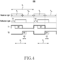
- FIG. 4 is a timing chart for explaining an example 400 of an operation of an electronic device (for example, the electronic device 301 of FIG. 3 ) according to an embodiment.
- the electronic device 301 may correspond to the electronic device 101 of FIG. 1 .
- the electronic device 301 may include a processor 310, a memory 330, a first sensor 340, and a second sensor 350.
- the first sensor 340 may photograph a still image and a moving image.
- the first sensor 340 may include one or more lenses, image sensors, image signal processors, or flashes.
- the second sensor 350 may acquire distance information (or depth information) between the electronic device 301 and a target object (for example, a subject) 302.
- the second sensor 350 may include a time of flight (ToF) module.
- the second sensor 350 may include a light emitter 352 and a receiver 354, or a combination thereof.
- the light emitter 352 may include one or more vertical-cavity surface emitting lasers (VCSELs), light emitting diodes (LEDs) (for example, a red-green-blud (RGB) LED, a white LED, an infrared LED, or an ultraviolet LED), or a xenon lamp.
- VCSELs vertical-cavity surface emitting lasers
- LEDs light emitting diodes
- the receiver 354 may be configured by an RGB sensor, a black and white (BW) sensor, an infrared sensor, an ultraviolet sensor, or a combination thereof.
- an image sensor included in the receiver 354 may be implemented by using a charged coupled device (CCD) sensor, a complementary metal oxide semiconductor (CMOS) sensor, or a combination thereof.
- CCD charged coupled device
- CMOS complementary metal oxide semiconductor
- the second sensor 350 may radiate radiation light 371 of a designated frequency to the target object 302 (for example, a subject, an external object, etc.) for a radiation time T p of a designated period T c , by using the light emitter 352.
- the second sensor 350 may not radiate the radiation light 371 for a non-radiation time T np of the designated period T c .
- the second sensor 350 may receive reflection light 375 from the target object 302 for a time of an interval corresponding to the radiation time T p by using the receiver 354.
- there may be a difference between a radiation time of the radiation light 371 and a reception time of the reflection light 375 as long as a time ⁇ t corresponding to a distance to the target object 302.
- the receiver 354 may include at least two capacitors T1, T2.
- the first capacitor T1 may switch from an off state to an on state for the radiation time T p of the designated period T c , and may switch from an on state to an off state for the non-radiation time T np .
- the second capacitor T 2 may switch from an on state to an off state for the radiation time T p of the designated period T c , and may switch from an off state to an on state for the non-radiation time T np .
- the at least two capacitors T1, T2 may accumulate quantities of electric charges (Q1, Q2) corresponding to a quantity of the reflection light 375 which enters while the capacitors are in the on state.
- the electric charges accumulated in the two capacitors T1, T2 may be electric charges which are generated in response to light received by the receiver.
- the second sensor 350 may transmit information indicating a distance D between the electronic device 301 and the target object 302 to the processor 310, or may transmit information indicating the time difference ⁇ t in order for the processor 310 to acquire information indicating the distance D.
- the second sensor 350 may be configured as a part of the first sensor 340.
- the first sensor 340 and the second sensor 350 may be configured by a single sensor, for example, an image sensor. However, this is merely an example and embodiments of the disclosure are not limited thereto.
- the processor 310 may control at least one other component (for example, the memory 330, the first sensor 340 or the second sensor 350) of the electronic device 301 which is connected to the processor 310.
- the processor 310 may control at least one other component (for example, the memory 330, the first sensor 340 or the second sensor 350) of the electronic device 301 which is connected to the processor 310.
- the processor 310 may enable the second sensor 350 and may acquire distance information between the electronic device 301 and the target object 302 by using the enabled second sensor 350.
- the input to measure the distance to the target object 302 may be received through a screen provided by a certain application.
- the input to measure the distance to the target object 302 may be an input to execute a certain application (for example, a camera application).
- a certain application for example, a camera application.
- the input to measure the distance to the target object 302 may be received through at least one of a voice command, a button input, a gesture input.
- ⁇ t indicates a time difference between a radiation time of the radiation light 371 and a reception time of the reflection light 375
- T p is a radiation time
- Q1 is a quantity of electric charges accumulated by the capacitor T 1 which switches to an on state for the radiation time Tp
- Q2 is a quantity of electric charges accumulated by the capacitor T 2 which switches to an on-state for the non-radiation time T np .
- the processor 310 may provide a service based on distance information measured by the second sensor 350.
- the service may be at least one function of distinguishing between a background and a target object in an image photographed through a camera.
- the processor 310 may distinguish between at least a portion (for example, background) included in the image and the other portion, based on the measured distance information, and may provide a service of applying different effects (for example, a blur effect) to one portion and the other portion which are distinguished.
- the processor 310 may identify at least one target object included in the image, based on the measured distance information, and may provide a service (for example, an AR Ruler service, a map service, a mixed reality service, etc.) of measuring at least one of information of a distance between the electronic device and the target object 302, a size of the target object 302, and a thickness of the target object 302.
- a service for example, an AR Ruler service, a map service, a mixed reality service, etc.
- a variety of information based on the distance information may be provided as a part of the service.
- the processor 310 may acquire distance information between the electronic device 301 and the target object 302 by using the first sensor 340.
- the threshold distance may be a distance between the electronic device 301 and the target object 302 that guarantees that an error of a distance measured by the second sensor 350 is less than or equal to a predetermined level. For example, when the measured distance is out of the threshold distance, the processor 310 may stop operating the second sensor 350 and may acquire distance information by using the first sensor 340.
- the processor 310 may stop operating the second sensor 350 and prevent unnecessary power consumption, and may identify a time to resume the operation of the second sensor 350 (for example, identifying the target object 302 existing within the threshold distance) by using the first sensor 340 which relatively less consumes power than the second sensor 350.
- the processor 310 may stop the operation of the second sensor 350 for a designated time, and may temporarily operate after the designated time and may identify a time to resume the operation of the second sensor 350.
- the processor 310 may stop providing the service based on the distance while acquiring distance information by using the first sensor 340.
- the processor 310 may notify a message informing that the operation of the second sensor 350 is stopped.
- the processor 310 may process to resume the stopped operation of the second sensor 350.
- the processor 310 may measure distance information by using the second sensor 350, and may provide the service based on the measured distance information.
- the processor 310 may change a measurement parameter while the second sensor 350 is operating.
- the measurement parameter may include a frequency of radiation (for example, a frequency), a radiation period (for example, an exposure time), a frame rate, etc. of the light emitter 352
- the processor 310 may change the measurement parameter based on a position of the target object 302. For example, as the distance to the target object 302 from the electronic device 301 is shorter, the processor 310 may reduce the radiation period and may increase the frequency of radiation. In addition, as the distance to the target object 302 from the electronic device 301 is longer, the processor 310 may increase the radiation period and may reduce the frequency of radiation. In addition, the processor 310 may reduce the frame rate in order to reduce power consumption while the second sensor 350 is operating. In another example, the processor 310 may change the measurement parameter based on a photographing environment. The photographing environment may be related to a type of the target object 302.
- the processor 310 may acquire distance information on the target object 302 by using a pre-designated reference parameter.
- the processor 310 may change the measurement parameter to extend a distance measurement range, for example, the threshold distance.
- the processor 310 may extend the distance measurement range by increasing the radiation period and reducing the frequency of radiation.
- the memory 330 may include at least one data necessary for measuring a distance to the target object 302.
- the memory may include data related to a measurement parameter and a threshold distance.
- the measurement parameter may include a frequency of radiation (for example, a frequency), a radiation period (for example, an exposure time), a frame rate, etc. of the light emitter, as described above.
- the measurement parameter may include various parameters such as an intensity of radiation of the light emitter.
- the measurement parameter may be defined according to a measurement environment.
- a measurement parameter suitable for a target object 302 which relatively less moves, and a measurement parameter suitable for a target object 302 which relatively more moves may be distinguished and may be stored.
- the measurement parameter may be defined according to a distance to the target object 302.
- the measurement parameter may include a parameter that should be changed to extend the threshold distance.
- an electronic device may include: a first sensor (for example, the first sensor 340) configured to acquire an image including at least one target object; a second sensor (for example, the second sensor 350) configured to generate depth data regarding the at least one target object; at least one processor (for example, the processor 310) operatively connected with the first sensor and the second sensor; and at least one memory (for example, the memory 330) operatively connected with the processor.
- a first sensor for example, the first sensor 340
- a second sensor for example, the second sensor 350
- at least one processor for example, the processor 310 operatively connected with the first sensor and the second sensor
- at least one memory for example, the memory 330
- the memory may store instructions that, when being executed, cause the processor to: while acquiring the image by using the first sensor, calculate a first distance between the at least one target object and the electronic device, based on the depth data generated by using the second sensor; stop an operation of the second sensor when the calculated first distance is longer than a designated distance; while the operation of the second sensor is stopped, calculate a second distance between the at least one target object and the electronic device, by using the first sensor; and, when the calculated second distance is within the designated distance, resume the operation of the second sensor.
- the instructions may cause the processor to calculate the second distance based on an auto focusing function of the first sensor.
- the instructions cause the processor to provide notification information informing that the calculated first distance is longer than the designated distance. According to an embodiment, the instructions may cause the processor to provide notification information including information for guiding to make the first distance included in the designated distance.
- the instructions may cause the processor to, when an input instructing the operation of the second sensor is received in a state where the calculated first distance is longer than the designated distance, extend the designated distance, to generate depth data regarding a target object existing within the extended designated distance, and to provide a service based on the generated depth data.
- the instructions may cause the processor to extend the designated distance by changing at least one of a frequency of radiation (for example, a frequency), a radiation period (for example, an exposure time), a frame rate of a light emitter (for example, the light emitter 352) related to the second sensor.
- a frequency of radiation for example, a frequency
- a radiation period for example, an exposure time
- a frame rate of a light emitter for example, the light emitter 352
- the instructions may cause the processor to, when it is impossible to calculate the second distance by using the first sensor, calculate the second distance by using the second sensor.
- the instructions may cause the processor to, when it is impossible to calculate the second distance by using the second sensor, terminate a function related to the second sensor.
- the instructions may cause the processor to: generate depth data while changing a measurement parameter of the reoperated second sensor; and provide a service based on the generated depth data.
- the measurement parameter may include at least one of a frequency of radiation, a radiation period, a frame rate of a light emitter related to the second sensor.
- the instructions may cause the processor to change the measurement parameter based on at least one of a photographing mode or environmental information.
- the photographing mode may include at least one of a moving image mode or a still image mode.
- the environmental information may include at least one of a movement of the target object, the number of the target obj ects, a type of the target object.
- the second sensor may generate the depth data by using a time at which light reflected from an object arrives.
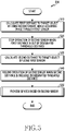
- FIG. 5 is a flowchart 500 for providing a service using depth information in the electronic device 301 according to various embodiments of the disclosure.
- respective operations may be performed in sequence, but may not necessarily be performed in sequence.
- the order of the respective operations may be changed and at least two operations may be performed in parallel.
- the electronic device 301 may acquire a first distance (or depth) to a target object 302 while acquiring an image.
- the processor 310 may acquire the image through the first sensor 340, and may acquire first distance information by using the second sensor 350 which is different from the first sensor 340.
- the second sensor 350 may include a time of flight (ToF) module.
- ToF time of flight
- the electronic device 301 may stop the operation of the second sensor 350 when the first distance measured by the processor 310 is out of a designated threshold distance.
- the designated threshold distance may be a distance between the electronic device 301 and the target object 302 that guarantees that an error of a distance measured by using the second sensor 350 is less than or equal to a predetermined level.
- the electronic device 301 may calculate a second distance to the target object 302 by using the first sensor 340.
- the processor 310 may acquire at least one image by using the first sensor 340, and may calculate a distance to the target object 302 based on the acquired image.
- the processor 310 may calculate the second distance based on auto focusing information through the at least one image.
- the electronic device 301 may include a plurality of first sensors 340.
- the processor 310 may calculate the second distance by using at least one first sensor 340 that does not acquire an image among the first sensors 340 having the same sensing range as the sensing range (for example, a field of view (FoV)) of the second sensor 350.
- the sensing range for example, a field of view (FoV)
- the electronic device 301 may process to resume the stopped operation of the second sensor 350.
- the processor 310 may process to resume the operation of the second sensor 350.
- the processor 310 may determine a time to resume the operation of the second sensor 350, based on the second distance. For example, the processor 310 may repeat operations related to operations 530 and 540.
- the electronic device 301 may provide a service based on the second sensor 350.
- the processor 310 may calculate a distance between the target object 302 and the electronic device 301 by using the second sensor 350, and may provide a service based on the calculated distance.
- the processor 310 may provide at least one of information of the distance to the target object 302, a size of the target object 302, a thickness of the target object 302 as a part of the service.
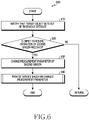
- FIG. 6 is a flowchart 600 for providing a service using depth information in the electronic device 301 according to various embodiments of the disclosure.
- FIG. 7 is a view 700 to explain an operation of notifying that the target object 302 gets out of a threshold distance in the electronic device 301 according to various embodiments of the disclosure.
- FIGS. 8A and 8B are views to explain an operation of changing a measurement parameter of the second sensor 350 in the electronic device 301 according to various embodiments. Operations of FIG. 6 described hereinbelow may indicate various embodiments of operation 520 of FIG. 5 .
- respective operations in the following embodiments may be performed in sequence, but may not necessarily be performed in sequence. For example, the order of the respective operations may be changed and at least two operations may be performed in parallel.
- the electronic device 301 may notify that the target object 302 gets out of a threshold distance.
- the processor 310 may notify that it is impossible to measure a distance to the target object 302 (710) as shown in FIG. 7 .
- the processor 310 may provide information for guiding to a region where it is possible to measure a distance (for example, "Move forward 1 meter!). This notification may include at least one of a visual notification, a tactile notification, an auditory notification.
- the electronic device 301 may determine whether a user input to resume the operation of the second sensor 350 is received.
- the user input may be an input instructing to measure the distance to the target object 302 although it is impossible to measure the distance to the target object 302.
- the electronic device 301 may stop the operation of the second sensor 350 and then may calculate a second distance to the target object 302 by using the first sensor 340.
- the electronic device 301 may change a measurement parameter of the second sensor 350 in operation 630.
- the processor 310 may change at least one measurement parameter in order to extend the threshold distance.
- the measurement parameter may include a frequency of radiation (for example, a frequency), a radiation period (for example, an exposure e time), a frame rate, etc. of the light emitter 352
- a parameter set as indicated by reference numeral 800 of FIG. 8A may be changed to a parameter as indicated by reference numeral 810.
- the processor 310 may extend the threshold distance by increasing the radiation period of the light emitter 352 from 570 ⁇ s (802) to 760 ⁇ s (812), and reducing the frequency of radiation of the light emitter 352 from 100 MHz (804) to 50 MHz (814). By extending the threshold distance, the processor 310 may make it possible to measure a distance to the target object 302 which gets out of the basic threshold distance. In addition, the processor 310 may change a parameter set as indicated by reference numeral 820 of FIG. 8B to a parameter as indicated by reference numeral 830 in order to reduce power consumption while the second sensor 350 is operating.
- the processor 310 may extend the threshold distance by increasing the radiation period of the light emitter 352 from 570 ⁇ s (822) to 760 ⁇ s (832), and reducing the frequency of radiation of the light emitter 352 from 100 MHz (824) to 50 MHz (834), and additionally, may prevent occurrence of power consumption by reducing the frame rate from 33.3 ms (826) to 50 ms (836) (for example, when the frame rate is reduced, power consumption may be reduced 0.88 times more than when the frame rate is not reduced.).
- the electronic device 301 may provide a service based on the changed measurement parameter.
- the processor 310 may measure a distance to the target object which gets out of the basic threshold distance, with the extended threshold distance.
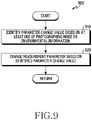
- FIG. 9 is a flowchart 900 for providing a service using depth information in the electronic device 301 according to various embodiments of the disclosure. Operations of FIG. 9 described hereinbelow may indicate various embodiments of operation 640 of FIG. 6 . In addition, respective operations in the following embodiments may be performed in sequence, but may not necessarily be performed in sequence. For example, the order of the respective operations may be changed and at least two operations may be performed in parallel.
- the electronic device 301 may identify a parameter change value based on at least one of a photographing mode or environmental information.
- the photographing mode may include at least one of a moving image mode or a still image mode.
- the environmental information may include at least one of an environment in which a target object 302 moving relatively less is photographed, an environment in which a target object 302 moving relatively more is photographed, an environment in which a pre-designated target object 302 is photographed, an environment in which a single target object 302 is photographed, an environment in which a plurality of target objects 302 are photographed.
- an inside (for example, the memory 330) of the electronic device 301 may store parameters corresponding to respective photographing modes and respective photographing environments, and the processor 310 may identify at least one of the photographing modes and/or the environmental information, based on information (or signal) acquired from the first sensor 340 and/or the second sensor 350. In addition, the processor 310 may determine a parameter value that should be changed, based on the stored parameter and the result of identifying.
- the electronic device 301 may change a measurement parameter based on the identified parameter change value.
- the processor 310 may variably extend the threshold distance by changing the parameter based on at least one of the photographing mode or the environmental information.
- the processor 210 may acquire distance information on the target object 302 by using the changed measurement parameter, and may provide a service by using the same.
- FIG. 10 is a flowchart 1000 for providing a service based on a changed measurement parameter in the electronic device 301 according to an embodiment of the disclosure.
- Operations of FIG. 10 described hereinbelow may indicate various embodiments of operation 640 of FIG. 6 .
- respective operations in the following embodiments may be performed in sequence, but may not necessarily be performed in sequence. For example, the order of the respective operations may be changed and at least two operations may be performed in parallel.
- the electronic device 301 may measure a third distance to the target object 302 by using the second sensor 350.
- the second sensor 350 may include a time of flight (ToF) module which radiates radiation light of a designated frequency to the target object 302, and acquires distance (or depth) information based on a reception time of the radiation light received from the target object 302.
- ToF time of flight
- the electronic device 301 may determine whether the third distance is included in a designated threshold distance.
- the threshold distance may be a distance between the electronic device 301 and the target object 302 that guarantees that an error of a distance measured by the second sensor 350 is less than or equal to a predetermined level.
- the processor 310 may determine whether the target object 302 getting out of the threshold distance enters the threshold distance again by using the second sensor 350.
- the electronic device 301 may restore the changed measurement parameter to the default parameter in operation 1030.
- the processor 310 may reduce power consumption of the electronic device 301 by restoring or changing the measurement parameter to correspond to the target object 302 which moves toward the electronic device 301.
- the processor 310 may change the measurement parameter by reducing the radiation period to a predetermined level (for example, reducing from 760 ⁇ s to 570 ⁇ s) and increasing the frequency of radiation (for example, increasing from 50 MHz to 100 MHz).
- the electronic device 310 when the measurement parameter is restored to the default parameter, the electronic device 310 (for example, the processor 310 of FIG. 3 ) may provide a service based on the default parameter in operation 1040.
- the processor 310 may provide a service based on distance information of the second sensor 350 which is acquired based on the default parameter.
- the processor 310 may perform at least one operation of operations 510 to 550 of FIG. 5 .
- the electronic device 301 may identify a providing time of the service which is provided based on the changed measurement parameter in operation 1050.
- the processor 310 may determine whether the service providing time exceeds a reference time.
- the processor 310 may perform the operation of measuring the third distance by using the second sensor 350.
- the processor 310 may stop the service when the service providing time exceeds the reference time.
- the processor 310 may determine that distance information may be acquired without guaranteeing accuracy, or power consumption of the electronic device 301 may continuously occur, and may stop providing the service.
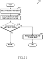
- FIG. 11 is a flowchart 1100 for acquiring distance information on the target object 302 by using the first sensor 340 in the electronic device 301 according to an embodiment of the disclosure.
- Operations of FIG. 11 described hereinbelow may indicate various embodiments of operation 530 of FIG. 5 .
- respective operations in the following embodiments may be performed in sequence, but may not necessarily be performed in sequence. For example, the order of the respective operations may be changed and at least two operations may be performed in parallel.
- the electronic device 301 may enable an auto focusing function of the first sensor 340.
- the auto focusing function may include a search position determination operation and an on-focus area detection operation.
- the search position determination operation may be an operation of determining a start position of the on-focus area detection operation.
- the on-focus area detection operation may be an operation of moving a focus lens with reference to a search position in phases and positioning in an on-focus area.
- the search position determination operation and the on-focus area detection operation described above may be referred to as various terms, and well-known various auto focusing functions may be performed in addition to the above-described auto focusing function.
- the electronic device 301 may calculate a distance to the target object 302 based on auto focusing information.
- the auto focusing information may include a focal distance to the target object 302, a moving distance of a lens, Etc.
- the electronic device 301 may determine whether the target object 302 is detected by using the first sensor 340.
- the electronic device 301 when the target object 302 is detected by using the first sensor 340, the electronic device 301 (for example, the processor 310 of FIG. 3 ) may perform an operation of comparing the distance to the detected target object 302 with a threshold distance. According to an embodiment, the processor 301 may perform an operation related to operation 540 of FIG. 5 .
- the electronic device 301 may terminate the function related to the second sensor 350 in operation 1140.
- the processor 310 may stop providing the service based on the distance information on the target object 302.
- FIG. 12 is a flowchart 1200 for determining whether to terminate the function related to the second sensor 350 in the electronic device 301 according to an embodiment.
- Operations of FIG. 12 described hereinbelow may indicate various embodiments of operation 1140 of FIG. 11 .
- respective operations in the following embodiments may be performed in sequence, but may not necessarily be performed in sequence. For example, the order of the respective operations may be changed and at least two operations may be performed in parallel.
- the electronic device 301 may resume the operation of the second sensor 350.
- the processor 310 may temporarily resume the operation of the second sensor 350 in response to the target object 302 not being detected through the first sensor 340.
- the electronic device 301 may change a measurement parameter of the second sensor 350 corresponding to a search mode.
- the search mode may refer to a mode for searching the target object 302 getting out of the threshold distance.
- the processor 310 may set the radiation period of the light emitter 352 to a maximum and may set the frequency of radiation of the light emitter 352 to a minimum in order to search the target object 302 getting out of the threshold distance.
- the electronic device 301 may calculate a distance to the target object 302 by using the second sensor 350.
- the electronic device 301 may determine whether the target object 302 is detected within a designated second threshold distance.
- the second threshold distance may be a criterion for determining a possibility that the target object 302 enters the above-described threshold distance.
- the second threshold distance may be longer than the above-described threshold distance and may be equal to or shorter than a third threshold distance that is detected through a search mode.
- the electronic device 301 may perform an operation of detecting the target object 302 in operation 1250.
- the processor 310 may acquire distance information on the target object 302 by using the first sensor 340 and/or the second sensor 350.
- the processor 310 may operate the first sensor 340 and/or the second sensor 350 for at least a predetermined time in order to acquire distance information on the target object 302.
- the electronic device 301 may terminate the function related to the second sensor 350.
- the processor 310 may stop providing the service based on the distance information on the target object 302 as described above. For example, when the target object 302 gets out of the designated second threshold distance, it may be interpreted that there is a low possibility that the target object 302 enters the above-described threshold distance. Accordingly, the processor 310 may stop the operation of acquiring distance information on the target object 302.
- FIG. 13 is a flowchart 1300 for providing a service based on the second sensor 350 in the electronic device 301 according to an embodiment of the disclosure.
- Operations of FIG. 13 described hereinbelow may indicate various embodiments of operation 550 of FIG. 5 .
- respective operations in the following embodiments may be performed in sequence, but may not necessarily be performed in sequence. For example, the order of the respective operations may be changed and at least two operations may be performed in parallel.
- the electronic device 301 may try to detect the target object 302 based on a first parameter.
- the first parameter may be default setting regarding a parameter which is used for detecting the target object 302 existing within the threshold distance.
- the electronic device 301 may determine whether the target object 302 is detected by using the first parameter.
- the electronic device 301 when the target object 302 is detected, the electronic device 301 (for example, the processor 310 of FIG. 3 ) may change a measurement parameter based on at least one of a distance to the target object 302 or a service type (for example, a photographing mode) in operation 1330.
- a measurement parameter based on at least one of a distance to the target object 302 or a service type (for example, a photographing mode) in operation 1330.
- the processor 310 may reduce the radiation period of the light emitter 352 to a designated level, and may increase the frequency of radiation of the light emitter 352 to a designated level as the distance to the target object 302 is shorter. In addition, in order to enhance accuracy of distance information, the processor 310 may increase the radiation period of the light emitter 352 to a designated level, and may reduce the frequency of radiation of the light emitter 352 to a designated level as the distance to the target object 302 is longer.
- the processor 310 may change the measurement parameter with reference to a position of a target object 302 existing at the longest distance.
- the processor 310 may increase the frame rate related to the second sensor 350 to a predetermined level in order to enhance accuracy of distance information.
- the processor 310 may reduce the frame rate related to the second sensor 350 to a predetermined level in order to enhance accuracy of distance information.
- the processor 301 may determine whether a time during which the target object 302 is not detected exceeds a reference time in operation 1340.
- the electronic device 301 when the time during which the target object 302 is not detected does not exceeds the reference time, the electronic device 301 (for example, the processor 310 of FIG. 3 ) may perform the operation of detecting the target object 302 based on the first parameter.
- the electronic device 301 may try to detect the target object 302 based on a second parameter in operation 1350.
- the processor 310 may change the first parameter to the second parameter in order to extend a target object 302 detectable distance.
- the processor 310 may change at least one of the frequency of radiation (for example, a frequency), the radiation period (for example, an exposure time), the frame rate of the light emitter 352 so as to make it possible to detect a target object existing out of the threshold distance.
- the processor 310 may change the first parameter in which the radiation period of the light emitter 352 is set to 570 ⁇ s and the frequency of radiation of the light emitter 352 is set to 100 MHz, to the second parameter in which the radiation period of the light emitter 352 increases to 760 ⁇ s and the frequency of radiation of the light emitter 352 is reduced to 50 MHz.
- FIG. 14 is another flowchart 1400 for providing a service based on the second sensor 350 in the electronic device 301 according to an embodiment of the disclosure.
- Operations of FIG. 14 described hereinbelow may indicate various embodiments of operation 550 of FIG. 5 .
- respective operations in the following embodiments may be performed in sequence, but may not necessarily be performed in sequence. For example, the order of the respective operations may be changed and at least two operations may be performed in parallel.
- the electronic device 301 may identify a target object by using the first sensor 340.
- the processor 310 may operate the first sensor 340 in order to identify the target object while the second sensor 350 is operating.
- the electronic device 301 may determine whether there exists a focus target object.
- the focus target object may be a target object that the electronic device focuses on among target objects included in an image acquired through the first sensor 340.
- the electronic device 301 when there does not exist the focus target object, the electronic device 301 (for example, the processor 310 of FIG. 3 ) may acquire distance information on the target object based on a currently set parameter.
- the electronic device 301 may calculate a distance to the focus target object in operation 1430.
- the processor 310 may calculate a distance to the target object 302 based on auto focusing information as described above.
- the electronic device 301 may change a measurement parameter based on the calculated distance.
- the processor 310 may reduce the radiation period of the light emitter 352 to a designated level, and may increase the frequency of radiation of the light emitter 352 to a designated level.
- the processor 310 may increase the radiation period of the light emitter 352 to a designated level, and may reduce the frequency of radiation of the light emitter 352 to a designated level.
- an operating method of an electronic device may include: while acquiring an image including at least one target object by using a first sensor (for example, the first sensor 340), generating depth data on the at least one target object by using a second sensor (for example, the second sensor 350); calculating a first distance between the at least one target object and the electronic device, based on the depth data; stopping an operation of the second sensor when the calculated first distance is longer than a designated distance; while the operation of the second sensor is stopped, calculating a second distance between the at least one target object and the electronic device, by using the first sensor; and, when the calculated second distance is within the designated distance, resuming the operation of the second sensor.
- the operating method of the electronic device may include calculating the second distance based on an auto focusing function of the first sensor.
- the operating method of the electronic device may include providing notification information informing that the calculated first distance is longer than the designated distance.
- the method may include providing notification information including information for guiding to make the first distance included in the designated distance.
- the operating method of the electronic device may include: when an input instructing the operation of the second sensor is received in a state where the calculated first distance is longer than the designated distance, extending the designated distance; generating depth data regarding a target object existing within the extended designated distance; and providing a service based on the generated depth data.
- the operating method of the electronic device may include extending the designated distance by changing at least one of a frequency of radiation (for example, a frequency), a radiation period (for example, an exposure time), a frame rate of a light emitter (for example, the light emitter 352) related to the second sensor.
- a frequency of radiation for example, a frequency
- a radiation period for example, an exposure time
- a frame rate of a light emitter for example, the light emitter 352
- the operating method of the electronic device may include, when it is impossible to calculate the second distance by using the first sensor, calculating the second distance by using the second sensor.
- the operating method of the electronic device may include, when it is impossible to calculate the second distance by using the second sensor, terminating a function related to the second sensor.
- the operating method of the electronic device may include: generating depth data while changing a measurement parameter of the reoperated second sensor; and providing a service based on the generated depth data.
- the measurement parameter may include at least one of a frequency of radiation, a radiation period, a frame rate of a light emitter related to the second sensor.
- the operating method of the electronic device may include changing the measurement parameter based on at least one of a photographing mode or environmental information.
- the photographing mode may include at least one of a moving image mode or a still image mode.
- the environmental information may include at least one of a movement of the target object, the number of the target obj ects, a type of the target object.
- the electronic device may be one of various types of electronic devices.
- the electronic devices may include, for example, a portable communication device (e.g., a smartphone), a computer device, a portable multimedia device, a portable medical device, a camera, a wearable device, or a home appliance. According to an embodiment of the disclosure, the electronic devices are not limited to those described above.
- each of such phrases as “A or B,” “at least one of A and B,” “at least one of A or B,” “A, B, or C,” “at least one of A, B, and C,” and “at least one of A, B, or C,” may include any one of, or all possible combinations of the items enumerated together in a corresponding one of the phrases.
- such terms as “1st” and “2nd,” or “first” and “second” may be used to simply distinguish a corresponding component from another, and does not limit the components in other aspect (e.g., importance or order).
- an element e.g., a first element
- the element may be coupled with the other element directly (e.g., wiredly), wirelessly, or via a third element.
- module may include a unit implemented in hardware, software, or firmware, and may interchangeably be used with other terms, for example, “logic,” “logic block,” “part,” or “circuitry”.
- a module may be a single integral component, or a minimum unit or part thereof, adapted to perform one or more functions.
- the module may be implemented in a form of an application-specific integrated circuit (ASIC).
- ASIC application-specific integrated circuit
- Various embodiments as set forth herein may be implemented as software (e.g., the program 140) including one or more instructions that are stored in a storage medium (e.g., internal memory 136 or external memory 138) that is readable by a machine (e.g., the electronic device 101) .
- a processor(e.g., the processor 120) of the machine e.g., the electronic device 101
- the one or more instructions may include a code generated by a complier or a code executable by an interpreter.
- the machine-readable storage medium may be provided in the form of a non-transitory storage medium.
- non-transitory simply means that the storage medium is a tangible device, and does not include a signal (e.g., an electromagnetic wave), but this term does not differentiate between where data is semipermanently stored in the storage medium and where the data is temporarily stored in the storage medium.
- a method may be included and provided in a computer program product.
- the computer program product may be traded as a product between a seller and a buyer.
- the computer program product may be distributed in the form of a machine-readable storage medium (e.g., compact disc read only memory (CD-ROM)), or be distributed (e.g., downloaded or uploaded) online via an application store (e.g., PlayStore TM ), or between two user devices (e.g., smart phones) directly. If distributed online, at least part of the computer program product may be temporarily generated or at least temporarily stored in the machine-readable storage medium, such as memory of the manufacturer's server, a server of the application store, or a relay server.
- CD-ROM compact disc read only memory
- an application store e.g., PlayStore TM
- two user devices e.g., smart phones
- each component e.g., a module or a program of the above-described components may include a single entity or multiple entities. According to various embodiments, one or more of the above-described components may be omitted, or one or more other components may be added. Alternatively or additionally, a plurality of components (e.g., modules or programs) may be integrated into a single component. In such a case, according to various embodiments, the integrated component may still perform one or more functions of each of the plurality of components in the same or similar manner as they are performed by a corresponding one of the plurality of components before the integration.
- operations performed by the module, the program, or another component may be carried out sequentially, in parallel, repeatedly, or heuristically, or one or more of the operations may be executed in a different order or omitted, or one or more other operations may be added.
Landscapes
- Engineering & Computer Science (AREA)
- Multimedia (AREA)
- Signal Processing (AREA)
- Physics & Mathematics (AREA)
- Remote Sensing (AREA)
- Radar, Positioning & Navigation (AREA)
- General Physics & Mathematics (AREA)
- Computer Networks & Wireless Communication (AREA)
- Electromagnetism (AREA)
- Human Computer Interaction (AREA)
- Computing Systems (AREA)
- Theoretical Computer Science (AREA)
- Studio Devices (AREA)
Applications Claiming Priority (2)
| Application Number | Priority Date | Filing Date | Title |
|---|---|---|---|
| KR1020190145704A KR102794864B1 (ko) | 2019-11-14 | 2019-11-14 | 카메라를 포함하는 전자 장치 및 그의 방법 |
| PCT/KR2020/015789 WO2021096219A1 (ko) | 2019-11-14 | 2020-11-11 | 카메라를 포함하는 전자 장치 및 그의 방법 |
Publications (3)
| Publication Number | Publication Date |
|---|---|
| EP4060976A1 true EP4060976A1 (de) | 2022-09-21 |
| EP4060976A4 EP4060976A4 (de) | 2023-01-11 |
| EP4060976B1 EP4060976B1 (de) | 2025-12-31 |
Family
ID=75912183
Family Applications (1)
| Application Number | Title | Priority Date | Filing Date |
|---|---|---|---|
| EP20888008.8A Active EP4060976B1 (de) | 2019-11-14 | 2020-11-11 | Elektronische vorrichtung mit kamera und verfahren dafür |
Country Status (5)
| Country | Link |
|---|---|
| US (1) | US12422553B2 (de) |
| EP (1) | EP4060976B1 (de) |
| KR (1) | KR102794864B1 (de) |
| CN (1) | CN114731362A (de) |
| WO (1) | WO2021096219A1 (de) |
Families Citing this family (5)
| Publication number | Priority date | Publication date | Assignee | Title |
|---|---|---|---|---|
| US11867798B2 (en) * | 2019-09-13 | 2024-01-09 | Samsung Electronics Co., Ltd. | Electronic device including sensor and method of determining path of electronic device |
| CN116762355A (zh) * | 2021-03-31 | 2023-09-15 | 深圳市大疆创新科技有限公司 | 视频拍摄方法、装置及系统 |
| KR20230018069A (ko) * | 2021-07-29 | 2023-02-07 | 삼성전자주식회사 | 카메라를 포함하는 전자 장치 및 전자 장치의 동작 방법 |
| CN113807172B (zh) * | 2021-08-11 | 2022-10-18 | 荣耀终端有限公司 | 一种人脸识别方法和装置 |
| CN118450251B (zh) * | 2023-12-22 | 2025-05-09 | 荣耀终端股份有限公司 | 摄像头使能优先级的管理方法、电子设备及存储介质 |
Family Cites Families (21)
| Publication number | Priority date | Publication date | Assignee | Title |
|---|---|---|---|---|
| JP2006105604A (ja) * | 2004-09-30 | 2006-04-20 | Fujinon Corp | 測距装置 |
| JP5308088B2 (ja) * | 2008-07-24 | 2013-10-09 | パナソニック株式会社 | 距離画像センサ |
| JP2012163940A (ja) | 2011-01-17 | 2012-08-30 | Ricoh Co Ltd | 撮像装置、撮像方法、及び撮像プログラム |
| KR20130102400A (ko) * | 2012-03-07 | 2013-09-17 | 삼성전자주식회사 | 티오에프 센서 및 티오에프 카메라 |
| US20140037135A1 (en) * | 2012-07-31 | 2014-02-06 | Omek Interactive, Ltd. | Context-driven adjustment of camera parameters |
| US9083960B2 (en) | 2013-01-30 | 2015-07-14 | Qualcomm Incorporated | Real-time 3D reconstruction with power efficient depth sensor usage |
| US9336440B2 (en) * | 2013-11-25 | 2016-05-10 | Qualcomm Incorporated | Power efficient use of a depth sensor on a mobile device |
| US10089740B2 (en) * | 2014-03-07 | 2018-10-02 | Fotonation Limited | System and methods for depth regularization and semiautomatic interactive matting using RGB-D images |
| JP6566800B2 (ja) * | 2014-09-30 | 2019-08-28 | キヤノン株式会社 | 撮像装置及び撮像方法 |
| US9967451B2 (en) | 2014-09-30 | 2018-05-08 | Canon Kabushiki Kaisha | Imaging apparatus and imaging method that determine whether an object exists in a refocusable range on the basis of distance information and pupil division of photoelectric converters |
| JP6603320B2 (ja) | 2015-08-28 | 2019-11-06 | 富士フイルム株式会社 | 距離画像取得装置付きプロジェクタ装置及びプロジェクションマッピング方法 |
| TWI706181B (zh) * | 2015-09-11 | 2020-10-01 | 新加坡商海特根微光學公司 | 具有自動對焦控制的成像裝置 |
| US10527423B1 (en) * | 2016-04-07 | 2020-01-07 | Luftronix, Inc. | Fusion of vision and depth sensors for navigation in complex environments |
| KR102627244B1 (ko) * | 2016-11-30 | 2024-01-22 | 삼성전자주식회사 | 전자 장치 및 전자 장치에서 홍채 인식을 위한 이미지 표시 방법 |
| US10009554B1 (en) * | 2017-02-24 | 2018-06-26 | Lighthouse Ai, Inc. | Method and system for using light emission by a depth-sensing camera to capture video images under low-light conditions |
| US11397077B2 (en) * | 2018-01-05 | 2022-07-26 | Stmicroelectronics, Inc. | Power and security adjustment for face identification with reflectivity detection by a ranging sensor |
| US10922395B2 (en) * | 2018-01-05 | 2021-02-16 | Stmicroelectronics, Inc. | Facial authentication systems and methods utilizing time of flight sensing |
| KR20200069096A (ko) * | 2018-12-06 | 2020-06-16 | 삼성전자주식회사 | 전자 장치 및 이를 이용하여 오브젝트의 깊이 정보를 획득하는 방법 |
| US11024041B2 (en) | 2018-12-10 | 2021-06-01 | Intel Corporation | Depth and motion estimations in machine learning environments |
| KR102716043B1 (ko) * | 2019-02-19 | 2024-10-14 | 삼성전자 주식회사 | 전자 장치 및 전자 장치의 오브젝트 측정 방법 |
| CN115118865A (zh) * | 2021-03-19 | 2022-09-27 | 北京小米移动软件有限公司 | 摄像装置控制方法、装置、电子设备及存储介质 |
-
2019
- 2019-11-14 KR KR1020190145704A patent/KR102794864B1/ko active Active
-
2020
- 2020-11-11 EP EP20888008.8A patent/EP4060976B1/de active Active
- 2020-11-11 WO PCT/KR2020/015789 patent/WO2021096219A1/ko not_active Ceased
- 2020-11-11 CN CN202080079431.5A patent/CN114731362A/zh active Pending
-
2022
- 2022-05-13 US US17/743,566 patent/US12422553B2/en active Active
Also Published As
| Publication number | Publication date |
|---|---|
| KR20210058363A (ko) | 2021-05-24 |
| WO2021096219A1 (ko) | 2021-05-20 |
| US20220268935A1 (en) | 2022-08-25 |
| US12422553B2 (en) | 2025-09-23 |
| EP4060976A4 (de) | 2023-01-11 |
| EP4060976B1 (de) | 2025-12-31 |
| KR102794864B1 (ko) | 2025-04-14 |
| CN114731362A (zh) | 2022-07-08 |
Similar Documents
| Publication | Publication Date | Title |
|---|---|---|
| EP3641294B1 (de) | Elektronische vorrichtung und verfahren zum erhalten von bildern | |
| US12422553B2 (en) | Electronic device comprising camera and method thereof | |
| KR102472156B1 (ko) | 전자 장치 및 그 깊이 정보 생성 방법 | |
| US11509815B2 (en) | Electronic device and method for processing image having human object and providing indicator indicating a ratio for the human object | |
| US11025890B2 (en) | Electronic device and method for acquiring depth information by using at least one of cameras or depth sensor | |
| US11467673B2 (en) | Method for controlling camera and electronic device therefor | |
| EP3718296B1 (de) | Elektronische vorrichtung und verfahren zur steuerung des autofokus von kameras | |
| KR20210046984A (ko) | 얼굴 데이터 획득을 위한 방법 및 이를 위한 전자 장치 | |
| US11297237B2 (en) | Electronic device for auto focusing function and operating method thereof | |
| US12360221B2 (en) | Electronic device and method for compensating for depth error according to modulation frequency | |
| KR20220005283A (ko) | 이미지 개선을 위한 전자장치 및 그 전자장치의 카메라 운용 방법 | |
| EP3718297B1 (de) | Verfahren zur anpassung des fokus auf basis eines spreizpegels eines anzeigeobjekts und elektronische vorrichtung zur unterstützung davon | |
| US12177565B2 (en) | Automatic focus detection method of camera and electric device supporting same | |
| KR20210144151A (ko) | Awb를 수행하여 이미지를 생성하는 전자 장치 및 방법 | |
| US11323610B2 (en) | Autofocus method and electronic device performing same | |
| US11392282B2 (en) | Electronic device for providing graphical content and method for controlling same | |
| KR20200092762A (ko) | 전자 장치 및 이를 이용한 카메라의 가림을 인식하는 방법 | |
| KR20210111554A (ko) | 이미지 센서 모듈 및 이를 포함하는 전자 장치 |
Legal Events
| Date | Code | Title | Description |
|---|---|---|---|
| STAA | Information on the status of an ep patent application or granted ep patent |
Free format text: STATUS: THE INTERNATIONAL PUBLICATION HAS BEEN MADE |
|
| PUAI | Public reference made under article 153(3) epc to a published international application that has entered the european phase |
Free format text: ORIGINAL CODE: 0009012 |
|
| STAA | Information on the status of an ep patent application or granted ep patent |
Free format text: STATUS: REQUEST FOR EXAMINATION WAS MADE |
|
| 17P | Request for examination filed |
Effective date: 20220614 |
|
| AK | Designated contracting states |
Kind code of ref document: A1 Designated state(s): AL AT BE BG CH CY CZ DE DK EE ES FI FR GB GR HR HU IE IS IT LI LT LU LV MC MK MT NL NO PL PT RO RS SE SI SK SM TR |
|
| A4 | Supplementary search report drawn up and despatched |
Effective date: 20221213 |
|
| RIC1 | Information provided on ipc code assigned before grant |
Ipc: H04N 5/235 20060101ALI20221207BHEP Ipc: H04N 5/232 20060101ALI20221207BHEP Ipc: H04N 5/225 20060101AFI20221207BHEP |
|
| DAV | Request for validation of the european patent (deleted) | ||
| DAX | Request for extension of the european patent (deleted) | ||
| STAA | Information on the status of an ep patent application or granted ep patent |
Free format text: STATUS: EXAMINATION IS IN PROGRESS |
|
| 17Q | First examination report despatched |
Effective date: 20240315 |
|
| REG | Reference to a national code |
Ref country code: DE Ref legal event code: R079 Free format text: PREVIOUS MAIN CLASS: H04N0005225000 Ipc: G01S0007497000 Ref country code: DE Ref legal event code: R079 Ref document number: 602020064951 Country of ref document: DE Free format text: PREVIOUS MAIN CLASS: H04N0005225000 Ipc: G01S0007497000 |
|
| RIC1 | Information provided on ipc code assigned before grant |
Ipc: G01S 7/497 20060101AFI20250715BHEP Ipc: G01S 17/86 20200101ALI20250715BHEP Ipc: G01S 17/88 20060101ALI20250715BHEP Ipc: H04N 23/61 20230101ALI20250715BHEP Ipc: H04N 23/63 20230101ALI20250715BHEP Ipc: H04N 23/65 20230101ALI20250715BHEP Ipc: H04N 23/67 20230101ALI20250715BHEP Ipc: H04N 23/959 20230101ALI20250715BHEP |
|
| GRAP | Despatch of communication of intention to grant a patent |
Free format text: ORIGINAL CODE: EPIDOSNIGR1 |
|
| STAA | Information on the status of an ep patent application or granted ep patent |
Free format text: STATUS: GRANT OF PATENT IS INTENDED |
|
| INTG | Intention to grant announced |
Effective date: 20250825 |
|
| GRAS | Grant fee paid |
Free format text: ORIGINAL CODE: EPIDOSNIGR3 |
|
| GRAA | (expected) grant |
Free format text: ORIGINAL CODE: 0009210 |
|
| STAA | Information on the status of an ep patent application or granted ep patent |
Free format text: STATUS: THE PATENT HAS BEEN GRANTED |
|
| AK | Designated contracting states |
Kind code of ref document: B1 Designated state(s): AL AT BE BG CH CY CZ DE DK EE ES FI FR GB GR HR HU IE IS IT LI LT LU LV MC MK MT NL NO PL PT RO RS SE SI SK SM TR |
|
| REG | Reference to a national code |
Ref country code: CH Ref legal event code: F10 Free format text: ST27 STATUS EVENT CODE: U-0-0-F10-F00 (AS PROVIDED BY THE NATIONAL OFFICE) Effective date: 20251231 Ref country code: GB Ref legal event code: FG4D |
|
| REG | Reference to a national code |
Ref country code: DE Ref legal event code: R096 Ref document number: 602020064951 Country of ref document: DE |
|
| REG | Reference to a national code |
Ref country code: IE Ref legal event code: FG4D |
|
| REG | Reference to a national code |
Ref country code: LT Ref legal event code: MG9D |
|
| PG25 | Lapsed in a contracting state [announced via postgrant information from national office to epo] |
Ref country code: NO Free format text: LAPSE BECAUSE OF FAILURE TO SUBMIT A TRANSLATION OF THE DESCRIPTION OR TO PAY THE FEE WITHIN THE PRESCRIBED TIME-LIMIT Effective date: 20260331 |
|
| PG25 | Lapsed in a contracting state [announced via postgrant information from national office to epo] |
Ref country code: HR Free format text: LAPSE BECAUSE OF FAILURE TO SUBMIT A TRANSLATION OF THE DESCRIPTION OR TO PAY THE FEE WITHIN THE PRESCRIBED TIME-LIMIT Effective date: 20251231 Ref country code: FI Free format text: LAPSE BECAUSE OF FAILURE TO SUBMIT A TRANSLATION OF THE DESCRIPTION OR TO PAY THE FEE WITHIN THE PRESCRIBED TIME-LIMIT Effective date: 20251231 |
|
| PG25 | Lapsed in a contracting state [announced via postgrant information from national office to epo] |
Ref country code: RS Free format text: LAPSE BECAUSE OF FAILURE TO SUBMIT A TRANSLATION OF THE DESCRIPTION OR TO PAY THE FEE WITHIN THE PRESCRIBED TIME-LIMIT Effective date: 20260331 |
|
| PG25 | Lapsed in a contracting state [announced via postgrant information from national office to epo] |
Ref country code: LV Free format text: LAPSE BECAUSE OF FAILURE TO SUBMIT A TRANSLATION OF THE DESCRIPTION OR TO PAY THE FEE WITHIN THE PRESCRIBED TIME-LIMIT Effective date: 20251231 |