EP4061971B1 - Plateau de transport permettant de transporter et de chauffer des substances chimiques - Google Patents
Plateau de transport permettant de transporter et de chauffer des substances chimiques Download PDFInfo
- Publication number
- EP4061971B1 EP4061971B1 EP19812726.8A EP19812726A EP4061971B1 EP 4061971 B1 EP4061971 B1 EP 4061971B1 EP 19812726 A EP19812726 A EP 19812726A EP 4061971 B1 EP4061971 B1 EP 4061971B1
- Authority
- EP
- European Patent Office
- Prior art keywords
- frame
- bottom plate
- screw
- base plate
- clamping
- Prior art date
- Legal status (The legal status is an assumption and is not a legal conclusion. Google has not performed a legal analysis and makes no representation as to the accuracy of the status listed.)
- Active
Links
Images



Classifications
-
- F—MECHANICAL ENGINEERING; LIGHTING; HEATING; WEAPONS; BLASTING
- F27—FURNACES; KILNS; OVENS; RETORTS
- F27D—DETAILS OR ACCESSORIES OF FURNACES, KILNS, OVENS OR RETORTS, IN SO FAR AS THEY ARE OF KINDS OCCURRING IN MORE THAN ONE KIND OF FURNACE
- F27D5/00—Supports, screens or the like for the charge within the furnace
- F27D5/0006—Composite supporting structures
-
- F—MECHANICAL ENGINEERING; LIGHTING; HEATING; WEAPONS; BLASTING
- F27—FURNACES; KILNS; OVENS; RETORTS
- F27D—DETAILS OR ACCESSORIES OF FURNACES, KILNS, OVENS OR RETORTS, IN SO FAR AS THEY ARE OF KINDS OCCURRING IN MORE THAN ONE KIND OF FURNACE
- F27D5/00—Supports, screens or the like for the charge within the furnace
- F27D5/0068—Containers
-
- C—CHEMISTRY; METALLURGY
- C21—METALLURGY OF IRON
- C21D—MODIFYING THE PHYSICAL STRUCTURE OF FERROUS METALS; GENERAL DEVICES FOR HEAT TREATMENT OF FERROUS OR NON-FERROUS METALS OR ALLOYS; MAKING METAL MALLEABLE, e.g. BY DECARBURISATION OR TEMPERING
- C21D9/00—Heat treatment, e.g. annealing, hardening, quenching or tempering, adapted for particular articles; Furnaces therefor
- C21D9/0006—Details, accessories not peculiar to any of the following furnaces
- C21D9/0025—Supports; Baskets; Containers; Covers
-
- F—MECHANICAL ENGINEERING; LIGHTING; HEATING; WEAPONS; BLASTING
- F27—FURNACES; KILNS; OVENS; RETORTS
- F27B—FURNACES, KILNS, OVENS OR RETORTS IN GENERAL; OPEN SINTERING OR LIKE APPARATUS
- F27B9/00—Furnaces through which the charge is moved mechanically, e.g. of tunnel type; Similar furnaces in which the charge moves by gravity
- F27B9/30—Details, accessories or equipment specially adapted for furnaces of these types
- F27B9/38—Arrangements of devices for charging
-
- F—MECHANICAL ENGINEERING; LIGHTING; HEATING; WEAPONS; BLASTING
- F27—FURNACES; KILNS; OVENS; RETORTS
- F27D—DETAILS OR ACCESSORIES OF FURNACES, KILNS, OVENS OR RETORTS, IN SO FAR AS THEY ARE OF KINDS OCCURRING IN MORE THAN ONE KIND OF FURNACE
- F27D5/00—Supports, screens or the like for the charge within the furnace
- F27D5/0006—Composite supporting structures
- F27D5/0012—Modules of the sagger or setter type; Supports built up from them
-
- F—MECHANICAL ENGINEERING; LIGHTING; HEATING; WEAPONS; BLASTING
- F27—FURNACES; KILNS; OVENS; RETORTS
- F27D—DETAILS OR ACCESSORIES OF FURNACES, KILNS, OVENS OR RETORTS, IN SO FAR AS THEY ARE OF KINDS OCCURRING IN MORE THAN ONE KIND OF FURNACE
- F27D5/00—Supports, screens or the like for the charge within the furnace
- F27D2005/0081—Details
-
- F—MECHANICAL ENGINEERING; LIGHTING; HEATING; WEAPONS; BLASTING
- F27—FURNACES; KILNS; OVENS; RETORTS
- F27D—DETAILS OR ACCESSORIES OF FURNACES, KILNS, OVENS OR RETORTS, IN SO FAR AS THEY ARE OF KINDS OCCURRING IN MORE THAN ONE KIND OF FURNACE
- F27D5/00—Supports, screens or the like for the charge within the furnace
- F27D2005/0081—Details
- F27D2005/0093—Means to maintain the form of the article
-
- H—ELECTRICITY
- H01—ELECTRIC ELEMENTS
- H01M—PROCESSES OR MEANS, e.g. BATTERIES, FOR THE DIRECT CONVERSION OF CHEMICAL ENERGY INTO ELECTRICAL ENERGY
- H01M10/00—Secondary cells; Manufacture thereof
- H01M10/05—Accumulators with non-aqueous electrolyte
- H01M10/052—Li-accumulators
- H01M10/0525—Rocking-chair batteries, i.e. batteries with lithium insertion or intercalation in both electrodes; Lithium-ion batteries
-
- H—ELECTRICITY
- H01—ELECTRIC ELEMENTS
- H01M—PROCESSES OR MEANS, e.g. BATTERIES, FOR THE DIRECT CONVERSION OF CHEMICAL ENERGY INTO ELECTRICAL ENERGY
- H01M4/00—Electrodes
- H01M4/02—Electrodes composed of, or comprising, active material
- H01M4/04—Processes of manufacture in general
- H01M4/0471—Processes of manufacture in general involving thermal treatment, e.g. firing, sintering, backing particulate active material, thermal decomposition, pyrolysis
-
- H—ELECTRICITY
- H01—ELECTRIC ELEMENTS
- H01M—PROCESSES OR MEANS, e.g. BATTERIES, FOR THE DIRECT CONVERSION OF CHEMICAL ENERGY INTO ELECTRICAL ENERGY
- H01M4/00—Electrodes
- H01M4/02—Electrodes composed of, or comprising, active material
- H01M4/13—Electrodes for accumulators with non-aqueous electrolyte, e.g. for lithium-accumulators; Processes of manufacture thereof
- H01M4/139—Processes of manufacture
- H01M4/1391—Processes of manufacture of electrodes based on mixed oxides or hydroxides, or on mixtures of oxides or hydroxides, e.g. LiCoOx
-
- Y—GENERAL TAGGING OF NEW TECHNOLOGICAL DEVELOPMENTS; GENERAL TAGGING OF CROSS-SECTIONAL TECHNOLOGIES SPANNING OVER SEVERAL SECTIONS OF THE IPC; TECHNICAL SUBJECTS COVERED BY FORMER USPC CROSS-REFERENCE ART COLLECTIONS [XRACs] AND DIGESTS
- Y02—TECHNOLOGIES OR APPLICATIONS FOR MITIGATION OR ADAPTATION AGAINST CLIMATE CHANGE
- Y02E—REDUCTION OF GREENHOUSE GAS [GHG] EMISSIONS, RELATED TO ENERGY GENERATION, TRANSMISSION OR DISTRIBUTION
- Y02E60/00—Enabling technologies; Technologies with a potential or indirect contribution to GHG emissions mitigation
- Y02E60/10—Energy storage using batteries
Definitions
- the present invention lies in the technical field of the thermal conversion of chemical substances in a furnace and relates to a transport trough which is suitable for transporting and heating chemical substances.
- Batteries are basically divided into primary and secondary energy storage devices. While in primary energy storage devices the chemical energy is irreversibly converted into electrical energy, secondary energy storage devices (accumulators) enable multiple use through the possibility of reversing the ongoing chemical reaction by supplying electrical energy.
- Secondary energy storage devices with an active cathode material based on lithium ions are used in a wide variety of applications. Examples include electric and hybrid vehicles, portable computers, mobile phones and smart watches.
- the widespread use of lithium ion batteries requires large quantities of active cathode materials. The quantities produced worldwide amount to more than one hundred thousand tons per year, and the trend is rising sharply. It is currently common to use lithium mixed metal oxides with the transition metals nickel (nickel), manganese (Mn) and cobalt (Co) as active cathode materials.
- cathode materials lithium nickel cobalt manganese oxide (LiNiCoMnOs) and lithium cobalt oxide (LiCoOs); Lithium nickel cobalt aluminum oxide (LiNiCoAlO 2 ) and lithium iron phosphate (LiFePo 4 ) are produced in smaller quantities.
- the respective starting materials are transported in a transport tray through a continuous furnace and heated to a temperature of several hundred degrees Celsius, for example, which leads to a chemical conversion to the desired product.
- the transport trays are subject to considerable corrosion.
- the reason for this is the chemical aggressiveness of the substances transported in the transport tray, which attack the material of the transport tray more strongly at the high temperatures in the continuous furnace.
- the transport tanks become very corroded due to the particularly aggressive transition metals. This has the disadvantage that the transport tanks can only be used for a relatively small number of times and then have to be replaced.
- a transport tank can usually only be used for 20 to 40 production cycles in the production of lithium nickel cobalt manganese oxide.
- the transport tanks contain residues of the cathode powder, which are usually classified as hazardous waste, meaning that complex and expensive disposal is necessary.
- this increases the production costs for the active cathode material in an undesirable way, and on the other hand, the hazardous waste resulting from the transport tanks having to be disposed of is ecologically undesirable.
- materials in the transport tank contaminate the cathode powder, which leads to its contamination and reduces its overall quality.
- CN105352328A and CN105841497A A transport tray can be removed from each one, the frame and base of which are connected to each other in a non-destructive manner.
- US 2015/241127 A1 shows a transport tray according to the preamble of claim 1. Further prior art can be US 2182201 A be taken.
- the object of the present invention is to improve transport trays for a continuous furnace known in the prior art in such a way that the costs for the large-scale production of chemical products are reduced and less hazardous waste has to be disposed of.
- the cathode powder should be less contaminated by the tray material.
- a transport trough for a furnace in particular a continuous furnace or shuttle furnace
- the transport trough serves as a trough-shaped container for transporting chemical substances, wherein the substances transported in the transport trough (starting materials) are to be converted into a chemical product by heating in the furnace in the transport trough.
- starting materials any starting materials can be converted into a chemical product in the transport trough according to the invention.
- nickel, manganese and cobalt can each be present alone or in any combination.
- the transport tray generally comprises a flat floor, at least inside the transport tray, and a surrounding frame which, together with the floor, forms a trough-shaped (i.e. upwardly open) cavity for holding chemical substances.
- the frame is connected to the floor in a non-destructive manner.
- the floor is connected to the frame in a form-fitting and/or force-fitting manner, whereby the floor can be removed from the frame without destroying the floor and frame.
- the floor and the surrounding frame each have surfaces which delimit the trough-shaped cavity, whereby the floor surface serves to support the chemical substances.
- the thermally induced conversion of the starting materials in the transport tray usually results in more severe corrosion on the bottom than on the frame.
- the reason for this is a slight loss of the substances transported in the transport tray, which, depending on the temperature, leads to reduced or even no contact with the inner surface of the frame, which results in less (contact) corrosion.
- the transport tray according to the invention makes advantageous use of this knowledge and, due to the detachable fastening of the bottom and frame, enables the possibly more heavily corroded bottom or part of the bottom to be replaced and the frame to be reused.
- the bottom detached from the frame can be subjected to targeted cleaning, for example by sandblasting, which may also allows for further use. This saves costs for the transport trays, which in turn saves the overall costs for the large-scale production of a product, particularly the active cathode material of a lithium-ion battery.
- the amount of hazardous waste to be disposed of is reduced.
- the frame and the floor are clamped or screwed together, with at least one corresponding connecting element (clamping element, screw element) being provided.
- clamped element clamped element
- screw element connecting element
- the base of the transport trough according to the invention can basically be made up of one or more parts.
- the base can consist of a single base plate, whereby the (single) base plate has a base surface which delimits the trough-shaped cavity and serves to support the chemical substances.
- the base can consist of several base plates which are arranged one above the other (in the vertical direction). Each base plate can be made up of one part or composed of several base plate elements.
- the top base plate has a base surface which delimits the trough-shaped cavity and serves to support the chemical substances.
- the closed frame has a clamping flange projecting outwards (in the direction away from the hollow space of the transport trough), wherein the base is firmly connected to the clamping flange of the frame by at least one clamping element.
- the closed frame has on its underside a support flange that projects inwards (towards the hollow space of the transport trough), which is preferably designed to be circumferential.
- the frame is particularly preferably firmly connected through the support flange to the base placed on the support flange by at least one screw element.
- the support flange is also a screw flange here, since it is used for screwing.
- the at least one screw element which passes through the support flange ends blindly in a threaded blind hole (ie a hole which does not completely penetrate the base) which is formed in the base.
- the base is designed in the form of a one-piece base plate, i.e. the base consists of the one-piece base plate.
- the one-piece base plate is firmly connected to the frame by at least one non-destructively detachable connecting means (e.g. clamping element, screw element).
- the one-piece base plate is firmly connected to the frame by at least one screw element, for which purpose the base plate is advantageously placed on the inwardly projecting support or screw flange.
- the one-piece base plate is firmly connected to the frame by at least one clamping element, wherein the at least one clamping element preferably engages the clamping flange of the frame.
- the floor consists of two floor plates that are arranged one above the other, so that an upper floor plate is arranged on a lower floor plate.
- the upper floor plate is composed of a plurality of, for example, strip-shaped floor plate elements, the lower floor plate is formed in one piece.
- the strip-shaped floor plate elements are preferably arranged next to one another.
- the one-piece lower floor plate, and possibly the upper floor plate, are firmly connected to the frame by at least one clamping element, for which purpose the frame advantageously has an outwardly projecting clamping flange. Clamping is carried out by at least one clamping element that engages the clamping flange.
- the upper floor plate or individual floor plate elements, and possibly also the lower floor plate, can be replaced. If necessary, individual floor plate elements of the upper floor plate and/or the one-piece lower floor plate can continue to be used, for example after cleaning.
- the floor consists of a floor plate which is composed of a plurality of, for example, strip-shaped floor plate elements which are arranged next to one another.
- the frame has an inwardly projecting support flange to which the strip-shaped Base plate elements rest on one another.
- at least one clamping element for example a clamping strip, is provided to firmly connect the strip-shaped base plate elements to the frame, the clamping element being screwed to the support flange (screw flange).
- at least one screw element is used, which passes through the support flange and ends in a threaded blind hole formed in a base plate element.
- the base plate elements further inside are clamped by at least one clamping strip, preferably two clamping strips.
- Two clamping strips arranged opposite one another are advantageous. This design also enables the entire base plate or individual base plate elements to be easily replaced, with individual base plate elements being able to be reused if necessary.
- the frame has a rectangular or square shape with two opposing (parallel) frame sections. Adjacent frame sections are advantageously connected to one another by an oblique corner (frame) section, with the corner section being arranged at an angle of greater than 0° and less than 90 to each of the two adjacent frame sections.
- frame oblique corner
- the frame has a separate clamping flange on each corner section, with the corner section being able to be offset inwards relative to the frame sections, for example.
- the frame has one or more clamping flanges.
- the clamping flanges can be used to create a separate clamping element.
- the frame is advantageously screwed to the floor, ie the frame and floor are firmly connected to one another by at least one screw connection.
- the screw connection is on the one hand a permanently fixed connection, but on the other hand it allows the floor and frame to be separated quickly and easily without causing any damage.
- the frame advantageously has at least one screw flange, which is designed in such a way that the floor can be placed as an insert through the frame onto the screw flange.
- one or more blind holes are formed below the cavity for a screw connection between the frame and the floor, which do not penetrate the floor.
- the blind holes are each provided with a thread for the engagement of a fastening screw.
- blind holes can advantageously prevent damage to the floor surface of the cavity.
- the screws are safely protected against corrosion.
- the (flat) inside floor surface can be easily cleaned, for example by sandblasting.
- the transport tank is typically made of a refractory material.
- the frame and base are preferably made of a ceramic material, which is preferably selected from the group cordierite, mullite, alumina, SiC, or mixtures thereof. Aluminum oxide/cordierite/spinel mixtures are common.
- the frame and base are preferably made of a SiC material, such as Si-SiC, in particular a porous SiC material, such as N-SiC and R-SiC, preferably silicon nitride, silicon oxynitride, or mixtures thereof. Due to the design-related improved thermal shock resistance compared to conventional "rigid" transport tanks, the frame and/or base can also be made of Al2O3-rich materials.
- the non-destructively detachable connection between the base and the frame also advantageously enables them to be manufactured from different materials.
- the base and frame are made of different materials, which are selected in such a way that the material of the base is more corrosion-resistant than the material of the frame in relation to the chemical conversion to the same product.
- the transport tray can thus be used more frequently, i.e. the number of production cycles until replacement due to corrosion is increased.
- the material of the base can be specifically selected with regard to corrosion stability when converting certain starting materials into a chemical product, thereby increasing the number of cycles.
- the base and frame of the transport tray according to the invention can be made of the same material. Cost savings in the large-scale production of a chemical product can This can be achieved simply by replacing the more heavily corroded floor or parts of the floor and reusing the frame.
- the base (and optionally also the frame) consists of a material that is particularly corrosion-resistant with regard to the production of active cathode materials based on lithium ions, which is preferably selected from the group consisting of aluminum oxide, zirconium oxide, magnesium oxide, R-SiC, N-SiC, S-SiC and Si-SiC, or mixtures thereof.
- the frame (and optionally also the base) preferably consists of aluminum oxide, R-SiC, N-SiC, S-SiC or Si-SiC, or a less corrosion-resistant but more cost-effective material such as SiC (oxide or nitride-bonded), cordierite or cordierite/spinel/mullite mixture.
- the transport tray is used particularly advantageously in the production of a (lithium-ion-based) active cathode material of a lithium-ion battery.
- the various embodiments of the invention can be implemented individually or in any combination.
- FIG. 1A a transport tray, designated overall by the reference number 1, according to a first embodiment of the invention is shown in a perspective view from above.
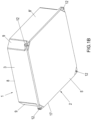
- Figure 1B shows the transport trough 1 in a perspective view from below.
- the transport trough 1 is used for the transport and heating of chemical substances, here for example in a continuous furnace.
- a continuous furnace comprises a roller bed with actively driven rollers, which together form a transport surface for the support and transport of the transport trough from a furnace entrance to a furnace exit. Since the specific structure of a continuous furnace is not necessary for understanding the invention, its description is unnecessary.
- the transport tray 1 comprises a base 2, which here consists of a flat, one-piece base plate 17.
- the base plate 17 has a front (upper) base surface 4 and a rear (lower) base surface 5.
- a surrounding, closed frame 3 is placed on the front base surface 4.
- the frame 3 is essentially rectangular in shape and comprises two opposing (parallel) frame sections 8 and 8', which are connected to one another by slanted corner sections 9.
- the corner sections 9 are each set back inwards towards the corners of the base 2.
- the frame 3 can be made of one or more parts.
- the frame sections 8, 8' are detachably or non-detachably connected to one another by the corner sections 9.
- the frame 3 has an inner frame surface 6 and an outer frame surface 7.
- the front base surface 4 and the inner frame surface 6 together delimit a trough-shaped cavity 13 that is open at the top and serves to hold starting materials that are to be converted into a chemical product by heating in the continuous furnace.
- the transport trough 1 is transported on the rear base surface 5 through a continuous furnace.
- the frame 3 is detachably but firmly connected to the base plate 17.
- the frame 3 has a clamping flange 10 on each of the inwardly offset corner sections 9.
- the clamping flanges 10 protrude outwards from the corner sections 9.
- Each clamping flange 10 has a top-side Clamping surface 11, which faces away from the rear base surface 5.
- a spring-elastic clamp 12 made of ceramic material, which serves as a clamping element, is clamped between the clamping surface 11 and the rear base surface 5, so that the base plate 17 and the frame 3 are pressed together by the spring-elastic force of the clamp 12. This achieves a permanently firm connection between the base plate 17 and the frame 3.
- the clamps 12 here have a U-shape, for example, and can be easily attached or removed in order to firmly connect or release the frame 3 and the base plate 17.
- the clamps are typically provided with a device (nose) so that they remain permanently in a locked state, which is not shown in more detail. Clamping at the four corner sections 9 ensures a permanently secure connection between the frame 3 and the base plate 17.
- the frame 3 and the base plate 17 can consist of different materials, with the base plate 17 advantageously consisting of a material which, in relation to the chemical conversion of the same product, is more corrosion-resistant than the material of the frame 3.
- the base plate 17 consists of a material which is selected from the group consisting of aluminum oxide, zirconium oxide, magnesium oxide, R-SiC, N-SiC, S-SiC and Si-SiC, or mixtures thereof.
- the frame 3 consists, for example, of cordierite or a cordierite/spinel/mullite mixture. However, it is also possible for the frame 3 and the base 2 to consist of the same material.
- frame 3 and base plate 17 In addition to the possibility of manufacturing frame 3 and base plate 17 from the same or different materials, their detachable assembly also enables easy replacement of the typically more corroded base plate 17.
- the base plate 17 can thus be easily removed and replaced by removing the clamps 12 from the frame 3, whereby the frame 3 is fitted with a new base plate 17. can be reused. This saves costs and materials. It is also possible to easily clean the front floor surface 4, for example by sandblasting.
- FIG. 2A a perspective view of the transport tray 1 from above, the base 2, which is designed in the form of a one-piece base plate 17, is placed with its rear base surface 5 in the form of an insert on the screw flange 14 from above.
- a firm connection between frame 3 and base plate 17 is made by respective screw connections on frame 3.
- the screw connection is in Figure 2C and Figure 2D shown enlarged in respective sectional views. Accordingly, for each frame section 8, 8', a blind-ended blind hole 15 is drilled from below, which passes through the screw flange 14 but does not break through the base plate 17, so that the front base surface 4 remains undamaged.
- the blind hole 15 is provided with a screw thread (not shown in detail) that is screwed to a screw 16.
- the screw thread can be screwed into the blind hole 15.
- a threaded sleeve can be inserted into the blind hole 15.
- the screws 16 are preferably accommodated with play in the thread, so that the play can accommodate different thermal expansions of the base plate 17 and frame 3. This also enables the use of materials whose thermal expansion coefficients differ significantly.
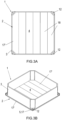
- Figure 3A and 3B show the top of the transport tray 1 in a view from above and a perspective view
- Figure 3C and Figure 3D show sectional views.
- the base 2 consists of a one-piece lower base plate 17 and a multi-piece upper base plate 17' arranged on top of it.
- the upper base plate 17' is composed of a plurality of strip-shaped base plate elements 18 which are arranged loosely next to one another.
- the upper base plate 17' is gap-free, i.e. the strip-shaped base plate elements 18 lie against one another without intermediate joints.
- the front base surface 4 is formed by the upper base plate 17'. Both base plates 17, 17' are clamped to the frame 3, for which purpose clamps 12 clamp the upper clamping surface 11 and the rear base surface 5 formed by the lower base plate 17.
- the two base plates 17, 17' are made of different materials.
- the upper base plate 17' is advantageously made of a material that, in relation to the chemical conversion of the same product, is more corrosion-resistant than the material of the lower base plate 17, which can save costs.
- the multi-part nature of the upper base plate 17 makes it easy to replace individual base plate elements 18. Likewise, the upper base plate 17' or the lower base plate 17 can be replaced separately.
- the multi-part nature (strips) increases the thermal shock resistance of the base plate 17' due to its design and allows the use of dense, more corrosion-resistant materials that would not withstand thermal shock loads if designed as a solid plate.
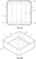
- Figure 4A to 4D taken, in which a fourth embodiment of the transport tray 1 according to the invention is illustrated using various perspective views. In order to avoid unnecessary repetition, only the differences from the second embodiment are explained and otherwise reference is made to the above statements.
- Figure 4A and 4B show the top of the transport tray 1 in a view from above and a perspective view
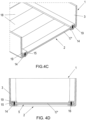
- Figure 4C and Figure 4D show sectional views.
- the frame 3 has a circumferential screw flange 14 that projects inwards.
- the base 2 which consists of a multi-part base plate 17', is placed with its rear base surface 5 in the form of an insert on the screw flange 14 from above.
- the base plate 17' is composed of a plurality of strip-shaped base plate elements 18 that are arranged loosely next to one another.
- the base plate 17' is gap-free, i.e. the strip-shaped base plate elements 18 lie against one another without intermediate joints.
- a firm connection between frame 3 and base plate 17' is made by screw connections, for which purpose blind holes 15 with blind ends are drilled into terminal strips 19 from below. Screws 16 pass through the screw flange 14 and the base plate 17' and end in the clamping strips 19.
- the two outermost base plate elements 18 are firmly connected to the frame by the screw connection.
- the base plate elements 18 are clamped against the screw flange 14 by the clamping strips 19.
- the transport tray 1 has two parallel clamping strips 19 that are opposite one another.
- the multi-part nature of the base plate 17' in turn enables the simple replacement of individual base plate elements 18 or the entire base plate 17'.
- the screws 16 are preferably accommodated with play in the thread so that the play can accommodate different thermal expansions of the base plate elements 18 and frame 3. This also enables the use of materials whose thermal expansion coefficients differ significantly.
- the invention provides an improved transport tray for the transport and heating of chemical substances.
- the detachable but firm connection of the frame and base enables the base, which is usually more heavily corroded, or parts thereof to be easily replaced and cleaned.
- the frame and base can be made of different materials.
- the overall lower costs for the transport trays can reduce the costs for the large-scale production of chemical products. This applies in particular to the production of active cathode materials for lithium-ion batteries.
- the hazardous waste generated by the corrosion-damaged transport trays can be reduced.
- the quality of the cathode material can be improved.
Landscapes
- Engineering & Computer Science (AREA)
- Chemical & Material Sciences (AREA)
- Mechanical Engineering (AREA)
- General Engineering & Computer Science (AREA)
- Chemical Kinetics & Catalysis (AREA)
- Electrochemistry (AREA)
- General Chemical & Material Sciences (AREA)
- Materials Engineering (AREA)
- Manufacturing & Machinery (AREA)
- Physics & Mathematics (AREA)
- Thermal Sciences (AREA)
- Crystallography & Structural Chemistry (AREA)
- Metallurgy (AREA)
- Organic Chemistry (AREA)
- Furnace Charging Or Discharging (AREA)
- Secondary Cells (AREA)
- Battery Electrode And Active Subsutance (AREA)
Claims (3)
- Bac de transport (1) pour le transport et le chauffage de substances chimiques pour la production d'un matériau de cathode pour une batterie lithium-ion, qui comprend:- un fond plat (2),- un cadre périphérique (3) qui forme avec le fond (2) une cavité en forme d'auge (1) pour recevoir les substances chimiques, dans lequel le cadre (3) est relié au fond (2) de manière non destructive, dans lequel le fond (2) et le cadre (3) sont constitués de matériaux différents l'un de l'autre, dans lequel le matériau du fond (2) est plus résistant à la corrosion que le matériau du cadre (3) en ce qui concerne la transformation chimique d'un même produit, caractérisé par le fait quei) le fond (2) est formé sous la forme d'une plaque de fond monobloc (17), dans laquelle la plaque de fond monobloc (17) est fixée au cadre (3), dans lequel au moins un élément de fixation (12) s'engage dans une bride de fixation (10) faisant saillie vers l'extérieur du cadre (3), ouii) le fond (2) est formé sous la forme d'une plaque de fond monobloc (17), dans laquelle la plaque de fond monobloc (17) est vissée au cadre (3), dans laquelle la plaque de fond (17) repose sur une bride de vis (14) faisant saillie vers l'intérieur du cadre (3) et au moins une vis (16) est vissée à la bride de vis, dans laquelle la vis (16) s'engage en particulier dans un trou borgne (15) de la plaque de fond (17), ouiii) le fond (2) est formé en plusieurs parties, dans lequel le fond (2) a une plaque de fond supérieure (17'), qui est formée d'une pluralité d'éléments de plaque de fond (18), par exemple en forme de bande, dans laquelle la plaque de fond supérieure (17') est disposée sur une plaque de fond inférieure d'une seule pièce (17), dans lequel la plaque de fond monobloc (17), et éventuellement la plaque de fond supérieure (17') formée d'une pluralité d'éléments de plaque de fond (18), est fixée au cadre (3), dans lequel au moins un élément de serrage (12) s'engage dans une bride de serrage (10) faisant saillie vers l'extérieur du cadre (3), ouiv) le fond (2) est formé en plusieurs parties, le fond (2) étant constitué d'une plaque de fond (17') formée d'une pluralité d'éléments de plaque de fond (18), par exemple en forme de bande, la plaque de fond (17') formée d'une pluralité d'éléments de plaque de fond (18) étant fixée au cadre (3), par exemple, par au moins une bande de serrage (19), dans lequel les éléments de la plaque inférieure (18) reposent sur une bride de vis (14) du cadre (3), dans lequel la au moins une bande de serrage (19) est vissée à la bride de vis (14) par au moins une vis (16), dans lequel la au moins une vis (16) s'engage en particulier dans un trou borgne (15) de la au moins une bande de serrage (19).
- Bac de transport (1) selon la revendication 1, dans laquelle le fond (2) est constitué d'un matériau choisi dans le groupe constitué par la cordiérite, la mullite, l'oxyde d'aluminium, l'oxyde de zirconium, l'oxyde de magnésium, le R-SiC, le N-SiC, le S-SiC et le Si-SiC, ou leurs mélanges, et dans lequel le cadre (3) est constitué d'un mélange cordiérite/spinel/mullite.
- Bac de transport (1) selon l'une quelconque des revendications 1 ou 2, dans laquelle le cadre (3) est composé d'une pluralité de pièces individuelles.
Priority Applications (1)
| Application Number | Priority Date | Filing Date | Title |
|---|---|---|---|
| PL19812726.8T PL4061971T3 (pl) | 2018-11-21 | 2019-11-21 | Korytko transportowe do przenoszenia i podgrzewania substancji chemicznych |
Applications Claiming Priority (2)
| Application Number | Priority Date | Filing Date | Title |
|---|---|---|---|
| DE102018129272.4A DE102018129272A1 (de) | 2018-11-21 | 2018-11-21 | Transportwanne für Durchlaufofen |
| PCT/EP2019/082089 WO2020104592A1 (fr) | 2018-11-21 | 2019-11-21 | Cuve de transport permettant de transporter et de chauffer des substances chimiques |
Publications (3)
| Publication Number | Publication Date |
|---|---|
| EP4061971A1 EP4061971A1 (fr) | 2022-09-28 |
| EP4061971B1 true EP4061971B1 (fr) | 2024-08-21 |
| EP4061971C0 EP4061971C0 (fr) | 2024-08-21 |
Family
ID=68731960
Family Applications (1)
| Application Number | Title | Priority Date | Filing Date |
|---|---|---|---|
| EP19812726.8A Active EP4061971B1 (fr) | 2018-11-21 | 2019-11-21 | Plateau de transport permettant de transporter et de chauffer des substances chimiques |
Country Status (8)
| Country | Link |
|---|---|
| US (1) | US12055347B2 (fr) |
| EP (1) | EP4061971B1 (fr) |
| JP (1) | JP7331104B2 (fr) |
| KR (1) | KR102503985B1 (fr) |
| CN (1) | CN113272460A (fr) |
| DE (1) | DE102018129272A1 (fr) |
| PL (1) | PL4061971T3 (fr) |
| WO (1) | WO2020104592A1 (fr) |
Families Citing this family (4)
| Publication number | Priority date | Publication date | Assignee | Title |
|---|---|---|---|---|
| DE102020000510B4 (de) * | 2020-01-28 | 2026-01-15 | Saint-Gobain Industriekeramik Rödental GmbH | Transportwanne zum Transportieren und Erhitzen chemischer Substanzen |
| WO2023062148A1 (fr) * | 2021-10-13 | 2023-04-20 | Saint-Gobain Industriekeramik Rödental GmbH | Cadre en plusieurs parties pour cuve de transport en céramique |
| SE2351019A1 (en) * | 2023-08-31 | 2025-03-01 | Northvolt Ab | A saggar having a replaceable base for use in battery manufacturing |
| CN118326146B (zh) * | 2024-06-12 | 2024-09-13 | 兴化市剑达铸造有限公司 | 一种球体零件热处理工序的承载料框 |
Family Cites Families (26)
| Publication number | Priority date | Publication date | Assignee | Title |
|---|---|---|---|---|
| US1186490A (en) * | 1915-08-26 | 1916-06-06 | American Dressler Tunnel Kilns Company Inc | Saggar. |
| US2182201A (en) * | 1937-07-28 | 1939-12-05 | Henry H Harris | Carburizing box |
| US2710746A (en) * | 1951-02-02 | 1955-06-14 | Paul S Menough | Annealing tray |
| SE418582B (sv) * | 1977-07-08 | 1981-06-15 | Grenges Weda Ab | Kerl for metallsmeltor |
| JPH0327280Y2 (fr) * | 1985-05-30 | 1991-06-12 | ||
| KR920005599Y1 (ko) * | 1990-03-24 | 1992-08-17 | 주식회사 요업개발공사 | 요업제품(전통고급 본차이나 유약소성전용)의 열처리용 내화갑 |
| US5900208A (en) * | 1995-10-10 | 1999-05-04 | Centorr/Vacuum Industries, Inc. | High-temperature flowable sintering bath and method of using same |
| US5935665A (en) * | 1996-10-29 | 1999-08-10 | Magneco/Metrel, Inc. | Firing container and method of making the same |
| JP2002029857A (ja) * | 2000-05-10 | 2002-01-29 | Mitsubishi Materials Corp | 小型セラミック電子部品焼成用トレイ |
| WO2007129391A1 (fr) * | 2006-05-01 | 2007-11-15 | Ibiden Co., Ltd. | Unité de montage de gabarit de cuisson, unité de démontage de gabarit de cuisson, appareil de circulation, procédé de moulage de céramique de cuisson, et processus de production de structure de nid d'abeille |
| CZ2010753A3 (cs) * | 2009-10-14 | 2012-02-15 | Imerys Magyarország Tüzállóanyaggyártó Kft. (Imerys Kiln Furniture Hungary Ltd.) | Žáruvzdorné príslušenství sušicí/vypalovací pece |
| JPWO2012133525A1 (ja) * | 2011-03-30 | 2014-07-28 | 京セラ株式会社 | 焼成用部材およびこれを用いた焼成用容器ならびに正極材料の製造方法 |
| CN103900385A (zh) * | 2012-12-24 | 2014-07-02 | 外杰希有限公司 | 热循环和安全性提高的耐火材料容器 |
| DE202013010392U1 (de) * | 2013-11-20 | 2013-11-29 | Sedlecký kaolin a.s. | Ofenwagenaufbau |
| CN103591808B (zh) * | 2013-11-21 | 2015-09-23 | 福州市陶瓷行业技术创新中心 | 可组装拆解的匣钵 |
| JP5824783B2 (ja) * | 2013-12-10 | 2015-12-02 | 太陽金網株式会社 | 熱処理用治具および熱処理用治具組立装置 |
| DE202014100849U1 (de) * | 2014-02-25 | 2014-05-12 | Imerys Kiln Furniture Hungary | Brennkapselanordnung |
| DE202014100848U1 (de) | 2014-02-25 | 2014-05-12 | Imerys Kiln Furniture Hungary | Brennkapselanordnung |
| CN105352328A (zh) * | 2014-08-18 | 2016-02-24 | 天津华夏泓源实业有限公司 | 一种正极材料用的装钵支撑装置 |
| KR101787638B1 (ko) * | 2014-11-05 | 2017-10-19 | 주식회사 엘지화학 | 이중 측벽 구조를 가지는 카트리지 프레임 및 이를 포함하는 배터리 모듈 |
| CN204235669U (zh) * | 2014-11-20 | 2015-04-01 | 宜兴中村窑业有限公司 | 一种匣钵及其制造模具 |
| CN105841497B (zh) * | 2016-05-18 | 2018-04-03 | 沈琦 | 三元锂电池正极材料专用匣钵 |
| CN207159795U (zh) * | 2017-09-11 | 2018-03-30 | 雨发建设集团有限公司 | 一种减震阻尼盆式橡胶支座 |
| DE102018119131A1 (de) * | 2018-08-07 | 2020-02-13 | Eisenmann Se | Behälter, Ofen und Verfahren zur Wärmebehandlung eines Pulvergemisches |
| DE102020000510B4 (de) * | 2020-01-28 | 2026-01-15 | Saint-Gobain Industriekeramik Rödental GmbH | Transportwanne zum Transportieren und Erhitzen chemischer Substanzen |
| KR20220043055A (ko) * | 2020-09-28 | 2022-04-05 | 엘지전자 주식회사 | 리튬이차전지 양극활물질 소성용 내화갑 및 그 제조 방법 |
-
2018
- 2018-11-21 DE DE102018129272.4A patent/DE102018129272A1/de active Pending
-
2019
- 2019-11-21 EP EP19812726.8A patent/EP4061971B1/fr active Active
- 2019-11-21 JP JP2021528412A patent/JP7331104B2/ja active Active
- 2019-11-21 CN CN201980077044.5A patent/CN113272460A/zh active Pending
- 2019-11-21 PL PL19812726.8T patent/PL4061971T3/pl unknown
- 2019-11-21 KR KR1020217018524A patent/KR102503985B1/ko active Active
- 2019-11-21 WO PCT/EP2019/082089 patent/WO2020104592A1/fr not_active Ceased
- 2019-11-21 US US17/295,755 patent/US12055347B2/en active Active
Also Published As
| Publication number | Publication date |
|---|---|
| EP4061971A1 (fr) | 2022-09-28 |
| US12055347B2 (en) | 2024-08-06 |
| US20220018601A1 (en) | 2022-01-20 |
| CN113272460A (zh) | 2021-08-17 |
| DE102018129272A1 (de) | 2020-05-28 |
| PL4061971T3 (pl) | 2024-11-04 |
| EP4061971C0 (fr) | 2024-08-21 |
| KR20210092273A (ko) | 2021-07-23 |
| JP2022507862A (ja) | 2022-01-18 |
| JP7331104B2 (ja) | 2023-08-22 |
| WO2020104592A1 (fr) | 2020-05-28 |
| KR102503985B1 (ko) | 2023-02-27 |
Similar Documents
| Publication | Publication Date | Title |
|---|---|---|
| EP4061971B1 (fr) | Plateau de transport permettant de transporter et de chauffer des substances chimiques | |
| EP4097410B1 (fr) | Cuve de transport permettant de transporter et de chauffer des substances chimiques | |
| EP3710229B1 (fr) | Système porteur pour une installation de fabrication et procédé correspondant | |
| EP2558378B1 (fr) | Boîte de transport | |
| DE202014100848U1 (de) | Brennkapselanordnung | |
| EP3833920B1 (fr) | Contenant, four et procédé de traitement thermique d'un mélange pulvérulent | |
| DE102014104398A1 (de) | Erwärmungsvorrichtung zum konduktiven Erwärmen einer Blechplatine | |
| DE102015110667B4 (de) | Zellenanordnung | |
| EP3271673B1 (fr) | Porte-charge | |
| DE102018207640A1 (de) | Kühlstruktur | |
| DE202014003519U1 (de) | Magnetrührer | |
| WO2014056837A1 (fr) | Emballage de transport destiné à une pièce formant palier annulaire, unité d'emballage l'utilisant et procédé d'emballage d'une pièce formant palier annulaire | |
| DE102018107535B4 (de) | Batteriesystem für ein Flurförderzeug und Verfahren zur Herstellung eines Batteriesystems | |
| DE102008011508A1 (de) | Energiespeicher sowie Verfahren zur Herstellung des Energiespeichers | |
| DE102018131123A1 (de) | Deckel für eine Mikrotiterplatte | |
| DE102017112366A1 (de) | Batteriemodul mit Kühlsystem | |
| WO1999047296A1 (fr) | Plaque d'obturation ainsi que busette a tiroir sur la busette de coulee d'un recipient contenant du metal en fusion | |
| DE102014112519A1 (de) | Abdeckelement für ein Verriegelungselement einer Küchenmaschine | |
| DE102014102249A1 (de) | Batterietrog und Batterieeinheit | |
| DE19608903C1 (de) | Befestigungsteil zur mittelbaren oder unmittelbaren Befestigung wenigstens eines Schaltschrank-Gerätes in einem Schaltschrank | |
| EP2735370A1 (fr) | Dispositif de remplacement d'une pièce d'usure | |
| DE102010003365A1 (de) | Vorrichtung zur Durchführung der PCR und PCR-Verfahren | |
| WO2020187597A1 (fr) | Bâti de chargement | |
| DE102013019228A1 (de) | Werkstückträger | |
| EP4416447A1 (fr) | Cadre en plusieurs parties pour cuve de transport en céramique |
Legal Events
| Date | Code | Title | Description |
|---|---|---|---|
| STAA | Information on the status of an ep patent application or granted ep patent |
Free format text: STATUS: UNKNOWN |
|
| STAA | Information on the status of an ep patent application or granted ep patent |
Free format text: STATUS: THE INTERNATIONAL PUBLICATION HAS BEEN MADE |
|
| PUAI | Public reference made under article 153(3) epc to a published international application that has entered the european phase |
Free format text: ORIGINAL CODE: 0009012 |
|
| STAA | Information on the status of an ep patent application or granted ep patent |
Free format text: STATUS: REQUEST FOR EXAMINATION WAS MADE |
|
| 17P | Request for examination filed |
Effective date: 20210427 |
|
| AK | Designated contracting states |
Kind code of ref document: A1 Designated state(s): AL AT BE BG CH CY CZ DE DK EE ES FI FR GB GR HR HU IE IS IT LI LT LU LV MC MK MT NL NO PL PT RO RS SE SI SK SM TR |
|
| DAV | Request for validation of the european patent (deleted) | ||
| DAX | Request for extension of the european patent (deleted) | ||
| STAA | Information on the status of an ep patent application or granted ep patent |
Free format text: STATUS: EXAMINATION IS IN PROGRESS |
|
| 17Q | First examination report despatched |
Effective date: 20230622 |
|
| GRAP | Despatch of communication of intention to grant a patent |
Free format text: ORIGINAL CODE: EPIDOSNIGR1 |
|
| STAA | Information on the status of an ep patent application or granted ep patent |
Free format text: STATUS: GRANT OF PATENT IS INTENDED |
|
| RIC1 | Information provided on ipc code assigned before grant |
Ipc: H01M 10/0525 20100101ALN20240207BHEP Ipc: H01M 4/1391 20100101ALI20240207BHEP Ipc: H01M 4/04 20060101ALI20240207BHEP Ipc: F27D 5/00 20060101ALI20240207BHEP Ipc: F27B 9/38 20060101ALI20240207BHEP Ipc: C21D 9/00 20060101AFI20240207BHEP |
|
| INTG | Intention to grant announced |
Effective date: 20240311 |
|
| GRAS | Grant fee paid |
Free format text: ORIGINAL CODE: EPIDOSNIGR3 |
|
| GRAA | (expected) grant |
Free format text: ORIGINAL CODE: 0009210 |
|
| STAA | Information on the status of an ep patent application or granted ep patent |
Free format text: STATUS: THE PATENT HAS BEEN GRANTED |
|
| AK | Designated contracting states |
Kind code of ref document: B1 Designated state(s): AL AT BE BG CH CY CZ DE DK EE ES FI FR GB GR HR HU IE IS IT LI LT LU LV MC MK MT NL NO PL PT RO RS SE SI SK SM TR |
|
| REG | Reference to a national code |
Ref country code: GB Ref legal event code: FG4D Free format text: NOT ENGLISH |
|
| REG | Reference to a national code |
Ref country code: CH Ref legal event code: EP |
|
| REG | Reference to a national code |
Ref country code: DE Ref legal event code: R096 Ref document number: 502019011953 Country of ref document: DE |
|
| REG | Reference to a national code |
Ref country code: IE Ref legal event code: FG4D Free format text: LANGUAGE OF EP DOCUMENT: GERMAN |
|
| U01 | Request for unitary effect filed |
Effective date: 20240902 |
|
| U07 | Unitary effect registered |
Designated state(s): AT BE BG DE DK EE FI FR IT LT LU LV MT NL PT RO SE SI Effective date: 20240916 |
|
| U20 | Renewal fee for the european patent with unitary effect paid |
Year of fee payment: 6 Effective date: 20241007 |
|
| PG25 | Lapsed in a contracting state [announced via postgrant information from national office to epo] |
Ref country code: NO Free format text: LAPSE BECAUSE OF FAILURE TO SUBMIT A TRANSLATION OF THE DESCRIPTION OR TO PAY THE FEE WITHIN THE PRESCRIBED TIME-LIMIT Effective date: 20241121 |
|
| PG25 | Lapsed in a contracting state [announced via postgrant information from national office to epo] |
Ref country code: GR Free format text: LAPSE BECAUSE OF FAILURE TO SUBMIT A TRANSLATION OF THE DESCRIPTION OR TO PAY THE FEE WITHIN THE PRESCRIBED TIME-LIMIT Effective date: 20241122 |
|
| PG25 | Lapsed in a contracting state [announced via postgrant information from national office to epo] |
Ref country code: IS Free format text: LAPSE BECAUSE OF FAILURE TO SUBMIT A TRANSLATION OF THE DESCRIPTION OR TO PAY THE FEE WITHIN THE PRESCRIBED TIME-LIMIT Effective date: 20241221 |
|
| PG25 | Lapsed in a contracting state [announced via postgrant information from national office to epo] |
Ref country code: HR Free format text: LAPSE BECAUSE OF FAILURE TO SUBMIT A TRANSLATION OF THE DESCRIPTION OR TO PAY THE FEE WITHIN THE PRESCRIBED TIME-LIMIT Effective date: 20240821 |
|
| PG25 | Lapsed in a contracting state [announced via postgrant information from national office to epo] |
Ref country code: RS Free format text: LAPSE BECAUSE OF FAILURE TO SUBMIT A TRANSLATION OF THE DESCRIPTION OR TO PAY THE FEE WITHIN THE PRESCRIBED TIME-LIMIT Effective date: 20241121 Ref country code: ES Free format text: LAPSE BECAUSE OF FAILURE TO SUBMIT A TRANSLATION OF THE DESCRIPTION OR TO PAY THE FEE WITHIN THE PRESCRIBED TIME-LIMIT Effective date: 20240821 |
|
| PG25 | Lapsed in a contracting state [announced via postgrant information from national office to epo] |
Ref country code: RS Free format text: LAPSE BECAUSE OF FAILURE TO SUBMIT A TRANSLATION OF THE DESCRIPTION OR TO PAY THE FEE WITHIN THE PRESCRIBED TIME-LIMIT Effective date: 20241121 Ref country code: NO Free format text: LAPSE BECAUSE OF FAILURE TO SUBMIT A TRANSLATION OF THE DESCRIPTION OR TO PAY THE FEE WITHIN THE PRESCRIBED TIME-LIMIT Effective date: 20241121 Ref country code: IS Free format text: LAPSE BECAUSE OF FAILURE TO SUBMIT A TRANSLATION OF THE DESCRIPTION OR TO PAY THE FEE WITHIN THE PRESCRIBED TIME-LIMIT Effective date: 20241221 Ref country code: HR Free format text: LAPSE BECAUSE OF FAILURE TO SUBMIT A TRANSLATION OF THE DESCRIPTION OR TO PAY THE FEE WITHIN THE PRESCRIBED TIME-LIMIT Effective date: 20240821 Ref country code: GR Free format text: LAPSE BECAUSE OF FAILURE TO SUBMIT A TRANSLATION OF THE DESCRIPTION OR TO PAY THE FEE WITHIN THE PRESCRIBED TIME-LIMIT Effective date: 20241122 Ref country code: ES Free format text: LAPSE BECAUSE OF FAILURE TO SUBMIT A TRANSLATION OF THE DESCRIPTION OR TO PAY THE FEE WITHIN THE PRESCRIBED TIME-LIMIT Effective date: 20240821 |
|
| PG25 | Lapsed in a contracting state [announced via postgrant information from national office to epo] |
Ref country code: SM Free format text: LAPSE BECAUSE OF FAILURE TO SUBMIT A TRANSLATION OF THE DESCRIPTION OR TO PAY THE FEE WITHIN THE PRESCRIBED TIME-LIMIT Effective date: 20240821 |
|
| PG25 | Lapsed in a contracting state [announced via postgrant information from national office to epo] |
Ref country code: CZ Free format text: LAPSE BECAUSE OF FAILURE TO SUBMIT A TRANSLATION OF THE DESCRIPTION OR TO PAY THE FEE WITHIN THE PRESCRIBED TIME-LIMIT Effective date: 20240821 |
|
| PG25 | Lapsed in a contracting state [announced via postgrant information from national office to epo] |
Ref country code: SK Free format text: LAPSE BECAUSE OF FAILURE TO SUBMIT A TRANSLATION OF THE DESCRIPTION OR TO PAY THE FEE WITHIN THE PRESCRIBED TIME-LIMIT Effective date: 20240821 |
|
| PLBE | No opposition filed within time limit |
Free format text: ORIGINAL CODE: 0009261 |
|
| STAA | Information on the status of an ep patent application or granted ep patent |
Free format text: STATUS: NO OPPOSITION FILED WITHIN TIME LIMIT |
|
| REG | Reference to a national code |
Ref country code: CH Ref legal event code: PL |
|
| PG25 | Lapsed in a contracting state [announced via postgrant information from national office to epo] |
Ref country code: MC Free format text: LAPSE BECAUSE OF FAILURE TO SUBMIT A TRANSLATION OF THE DESCRIPTION OR TO PAY THE FEE WITHIN THE PRESCRIBED TIME-LIMIT Effective date: 20240821 |
|
| REG | Reference to a national code |
Ref country code: CH Ref legal event code: PL |
|
| PG25 | Lapsed in a contracting state [announced via postgrant information from national office to epo] |
Ref country code: CH Free format text: LAPSE BECAUSE OF NON-PAYMENT OF DUE FEES Effective date: 20241130 |
|
| 26N | No opposition filed |
Effective date: 20250522 |
|
| PG25 | Lapsed in a contracting state [announced via postgrant information from national office to epo] |
Ref country code: IE Free format text: LAPSE BECAUSE OF NON-PAYMENT OF DUE FEES Effective date: 20241121 |
|
| U20 | Renewal fee for the european patent with unitary effect paid |
Year of fee payment: 7 Effective date: 20251008 |
|
| PGFP | Annual fee paid to national office [announced via postgrant information from national office to epo] |
Ref country code: GB Payment date: 20251001 Year of fee payment: 7 |
|
| PGFP | Annual fee paid to national office [announced via postgrant information from national office to epo] |
Ref country code: PL Payment date: 20251011 Year of fee payment: 7 |
|
| PG25 | Lapsed in a contracting state [announced via postgrant information from national office to epo] |
Ref country code: HU Free format text: LAPSE BECAUSE OF FAILURE TO SUBMIT A TRANSLATION OF THE DESCRIPTION OR TO PAY THE FEE WITHIN THE PRESCRIBED TIME-LIMIT; INVALID AB INITIO Effective date: 20191121 |
|
| PG25 | Lapsed in a contracting state [announced via postgrant information from national office to epo] |
Ref country code: CY Free format text: LAPSE BECAUSE OF FAILURE TO SUBMIT A TRANSLATION OF THE DESCRIPTION OR TO PAY THE FEE WITHIN THE PRESCRIBED TIME-LIMIT; INVALID AB INITIO Effective date: 20191121 |