EP4097410B1 - Cuve de transport permettant de transporter et de chauffer des substances chimiques - Google Patents
Cuve de transport permettant de transporter et de chauffer des substances chimiques Download PDFInfo
- Publication number
- EP4097410B1 EP4097410B1 EP21703842.1A EP21703842A EP4097410B1 EP 4097410 B1 EP4097410 B1 EP 4097410B1 EP 21703842 A EP21703842 A EP 21703842A EP 4097410 B1 EP4097410 B1 EP 4097410B1
- Authority
- EP
- European Patent Office
- Prior art keywords
- frame
- support structure
- transport tray
- oxide
- base plate
- Prior art date
- Legal status (The legal status is an assumption and is not a legal conclusion. Google has not performed a legal analysis and makes no representation as to the accuracy of the status listed.)
- Active
Links
Images






Classifications
-
- F—MECHANICAL ENGINEERING; LIGHTING; HEATING; WEAPONS; BLASTING
- F27—FURNACES; KILNS; OVENS; RETORTS
- F27D—DETAILS OR ACCESSORIES OF FURNACES, KILNS, OVENS OR RETORTS, IN SO FAR AS THEY ARE OF KINDS OCCURRING IN MORE THAN ONE KIND OF FURNACE
- F27D5/00—Supports, screens or the like for the charge within the furnace
- F27D5/0006—Composite supporting structures
-
- F—MECHANICAL ENGINEERING; LIGHTING; HEATING; WEAPONS; BLASTING
- F27—FURNACES; KILNS; OVENS; RETORTS
- F27D—DETAILS OR ACCESSORIES OF FURNACES, KILNS, OVENS OR RETORTS, IN SO FAR AS THEY ARE OF KINDS OCCURRING IN MORE THAN ONE KIND OF FURNACE
- F27D5/00—Supports, screens or the like for the charge within the furnace
- F27D5/0068—Containers
-
- H—ELECTRICITY
- H01—ELECTRIC ELEMENTS
- H01M—PROCESSES OR MEANS, e.g. BATTERIES, FOR THE DIRECT CONVERSION OF CHEMICAL ENERGY INTO ELECTRICAL ENERGY
- H01M4/00—Electrodes
- H01M4/02—Electrodes composed of, or comprising, active material
- H01M4/04—Processes of manufacture in general
- H01M4/0471—Processes of manufacture in general involving thermal treatment, e.g. firing, sintering, backing particulate active material, thermal decomposition, pyrolysis
-
- H—ELECTRICITY
- H01—ELECTRIC ELEMENTS
- H01M—PROCESSES OR MEANS, e.g. BATTERIES, FOR THE DIRECT CONVERSION OF CHEMICAL ENERGY INTO ELECTRICAL ENERGY
- H01M4/00—Electrodes
- H01M4/02—Electrodes composed of, or comprising, active material
- H01M2004/026—Electrodes composed of, or comprising, active material characterised by the polarity
- H01M2004/028—Positive electrodes
-
- Y—GENERAL TAGGING OF NEW TECHNOLOGICAL DEVELOPMENTS; GENERAL TAGGING OF CROSS-SECTIONAL TECHNOLOGIES SPANNING OVER SEVERAL SECTIONS OF THE IPC; TECHNICAL SUBJECTS COVERED BY FORMER USPC CROSS-REFERENCE ART COLLECTIONS [XRACs] AND DIGESTS
- Y02—TECHNOLOGIES OR APPLICATIONS FOR MITIGATION OR ADAPTATION AGAINST CLIMATE CHANGE
- Y02E—REDUCTION OF GREENHOUSE GAS [GHG] EMISSIONS, RELATED TO ENERGY GENERATION, TRANSMISSION OR DISTRIBUTION
- Y02E60/00—Enabling technologies; Technologies with a potential or indirect contribution to GHG emissions mitigation
- Y02E60/10—Energy storage using batteries
Definitions
- the present invention lies in the technical field of the thermal conversion of chemical substances in a furnace and relates to a transport tray suitable and intended for transporting and heating chemical substances. Furthermore, the invention relates to the use of a transport tray according to the invention in the production of cathode materials for lithium-ion batteries.
- Batteries are generally divided into primary and secondary energy storage devices. While in primary energy storage devices, chemical energy is irreversibly converted into electrical energy, secondary energy storage devices (accumulators) enable multiple uses thanks to the ability to reverse the ongoing chemical reaction by supplying electrical energy. Secondary energy storage devices with an active cathode material based on lithium-ion are used in a wide variety of applications. Examples include electric and hybrid vehicles, portable computers, mobile phones, and smart watches. The widespread use of lithium-ion batteries requires large quantities of active cathode materials. The quantities produced worldwide amount to more than 100,000 tons per year, and this figure is rising sharply. Currently, the most common active cathode material used is lithium mixed metal oxides with the transition metals nickel (nickel), manganese (Mn), and cobalt (Co).
- cathode materials lithium nickel cobalt manganese oxide (LiNiCoMnO 2 ) and lithium cobalt oxide (LiCoO 2 ); lithium nickel cobalt aluminum oxide (LiNiCoAlO 2 ) and lithium iron phosphate (LiFePo 4 ) are produced in smaller quantities.
- the respective starting materials are transported in a transport tray through a continuous furnace and heated to a temperature of several hundred degrees Celsius (e.g., 950 °C), which initiates a chemical conversion to the desired product.
- a temperature of several hundred degrees Celsius e.g., 950 °C
- the materials of the transport trays currently used are selected with regard to the high thermal shock resistance required for their application.
- the EP 0 452 718 B1 discloses annealing vessels for the heat treatment of contents arranged therein, with a bottom and side walls made of carbon reinforced with carbon fibres.
- DE 10 2011 052 016 A 1 discloses a kit for a crucible for holding molten material, for example molten silicon.
- Carriers for components to be subjected to a heat treatment process are in the WO 2004/111562 A2 described.
- CN 107 883 774 A discloses a transport tray with an outer support structure and a rigid frame inserted therein.
- the object of the present invention is to improve transport trays known in the prior art in such a way that the transport trays have a high resistance to temperature changes and at the same time good corrosion resistance and can therefore be used more frequently than transport trays known in the prior art.
- a transport trough for a furnace in particular a continuous furnace or bogie hearth furnace, according to the features of the independent patent claim.
- Advantageous embodiments of the invention are specified by the features of the subclaims.
- a transport trough for a furnace in particular a continuous furnace or shuttle furnace
- the transport trough serves as a trough-shaped container for transporting chemical substances, wherein the substances transported in the transport trough (starting materials) are to be converted into a chemical product by heating in the furnace in the transport trough.
- starting materials any starting materials can be converted into a chemical product in the transport trough according to the invention.
- nickel, manganese and cobalt can each be present alone or in any combination.
- the transport tank according to the invention for transporting and heating chemical substances comprises a support structure with a preferably flat base and a frame firmly connected thereto.
- the base and frame of the support structure are formed as one piece and cannot be separated from each other without causing damage.
- the transport trough further comprises a multi-component lining (wall or boundary) of a trough-shaped cavity that serves to contain the chemical substances.
- the lining is supported by the support structure.
- the lining comprises a base plate placed on the ground and several frame plates attached (i.e., fixed) to the frame. The frame plates are preferably clamped against the frame.
- the floor slab is supported by the support structure in such a way that, relative to the plane of the floor slab, it has free space (clearance) in at least two orthogonal directions, so that its thermal expansion is not impeded.
- the floor slab is supported by the support structure in such a way that its thermal expansion in the plane of the slab is not impeded.
- the floor slab is supported by the base of the support structure.
- the floor slab has free space all around in the plane of the slab.
- the floor slab is supported by the support structure in such a way that it has sufficient play (i.e. clearance) in the plane of the slab so that its thermal expansion is not impeded.
- each frame plate is fixed to the frame, preferably clamped against the frame, in such a way that it has free space (clearance) in the plate plane in at least two orthogonal directions, so that its thermal expansion is not impeded.
- each frame plate is supported by the support structure in such a way that its thermal expansion in the plate plane is not impeded.
- each frame plate is clamped against the frame.
- each frame plate is supported by the support structure in such a way that it has sufficient play (i.e., free space) in the plate plane so that its thermal expansion is not impeded.
- the special design of the lining of the trough-shaped cavity of the transport trough which does not impair the thermal expansion of the base and frame plates, prevents thermally induced mechanical stresses that would otherwise make material fracture likely.
- the lining can therefore be made of a material that has good corrosion resistance without the risk of material fracture due to the typically low thermal shock resistance of these materials. Materials with low thermal shock resistance can break more easily under thermally induced mechanical stresses.
- the material of the support structure, on the other hand, which is protected from corrosion by the lining, can be selected with a view to the desired high thermal shock resistance.
- the transport trough according to the invention can therefore advantageously be used far more frequently than conventional transport troughs before it needs to be replaced. For example, transport troughs according to the invention can be used at least 100 times more often than conventional transport troughs for the same purpose.
- the materials used for the lining can be selected to be highly corrosion-resistant.
- the structural design of the lining ensures resistance to thermal shock.
- the wall thickness of the floor and frame panels is preferably in the range of 1.5 mm to 8.0 mm, particularly preferably in the range of 2.0 mm to 5.0 mm.
- the frame panels can also be provided as a film with a wall thickness in the range from 0.3 mm to 2.5 mm.
- the thickness of the support structure is advantageously in the range of 6 to 12 mm and is preferably 7 mm.
- I(TWB) is an indicator of a material's thermal shock resistance.
- thermal shock resistance is inversely proportional to the plate thickness T, i.e., the smaller the plate thickness T, the greater the thermal shock resistance.
- the lining of the trough-shaped cavity, or parts thereof, can be replaced separately, while the support structure can generally be reused.
- the costs for producing substances using transport troughs according to the invention can thus be significantly reduced. Furthermore, significantly less hazardous waste is generated for disposal. Furthermore, contamination of the firing material is reduced, thus improving its quality.
- the base plate of the lining can be constructed in one or more parts.
- the base plate is constructed in one piece. If the base plate is constructed in several parts, it is composed, for example, of several strips.
- each frame plate can be constructed in one or more parts, with a one-piece design being preferred.
- the transport trough is advantageously designed in such a way that no parts protrude into the trough-shaped cavity which are not part of the lining, in particular no screws which serve to fasten the frame plates.
- the frame plates are clamped to the frame of the support structure by clamping strips.
- two adjacent frame plates are clamped against the frame by a clamping strip.
- the clamping strips each have at least one groove for receiving an edge region of an adjacent frame plate, wherein the edge region is received with play in the groove of the clamping strip.
- the clamping strips each have grooves for receiving edge regions of the frame plates. The edge regions of the frame plates adjacent to a clamping strip are received with play in the grooves of the clamping strips to allow for thermal expansion of the frame plates.
- the clamping strips for clamping the frame plates are advantageously clamped to the frame by threaded screws or spring-elastic clamps made of an inert ceramic material.
- the threaded screws or clamps used here are heat- and corrosion-resistant.
- the threaded screws and clamps are preferably made of a ceramic material, such as zirconium oxide, magnesium oxide, aluminum oxide, or mixtures thereof, with this material preferably accounting for at least 80% of the total.
- the clamping strips are each clamped to a corner section of the frame.
- the clamping strips can also be referred to as corner pieces.
- the clamping strips contain aluminum/magnesium spinel, yttrium oxide (Y 2 O 3 ), cerium oxide (CeO 2 ), hafnium oxide, aluminum oxide (Al 2 O 3 ), zirconium oxide (ZrO 2 ), magnesium oxide (MgO), or mixtures thereof, preferably at least 80%, particularly preferably at least 90%.
- the clamping strips can consist of aluminum oxide (Al 2 O 3 ), zirconium oxide (ZrO 2 ), magnesium oxide (MgO), or mixtures thereof.
- the frame of the support structure is a closed or circumferential frame.
- the circumferential frame of the support structure has plate-shaped frame sections
- the frame has a rectangular or square shape, each with two opposing (parallel) frame sections.
- adjacent frame sections are connected by a (slanted) corner section, with the corner section being arranged at an angle of greater than 0° and less than 90° to each of the two adjacent frame sections.
- At least one plate-shaped frame section of the frame of the support structure has at least one recess, in particular exactly one recess.
- all plate-shaped frame sections each have at least one recess, in particular exactly one recess.
- the at least one recess allows weight and material, as well as manufacturing costs, to be saved for the transport tray. Another advantage is the improved heat transfer to the firing material in the region of the recess achieved as a result, which reduces the disadvantage of the typically poorer thermal conductivity of materials with good corrosion resistance. Furthermore, the thermal load on the lining can be reduced.
- the at least one recess of a plate-shaped frame section of the support structure extends over at least 50%, at least 60%, at least 70%, at least 80% or at least 90% of the area of the plate-shaped frame section of the frame, wherein an increasingly larger extension of the recess is accompanied by better heat transfer and greater savings in material and costs.
- the at least one recess in the plate-shaped frame section of the support structure can be an internal recess, i.e., it is completely surrounded by material of the frame section.
- the associated frame plate of the lining is still well protected against mechanical stress by the frame section of the support structure and can therefore be designed with extremely thin walls.
- the wall thickness of the frame plate is in the range of 0.3 mm to 8.0 mm.
- the wall thickness is, for example, in the range of 0.3 mm to 2.0 mm.
- the at least one recess in the plate-shaped frame section of the support structure is a peripheral recess. This allows for a further improvement in heat transfer to the firing material and further savings in material and costs by further increasing the size of the recess.
- the base of the support structure has a plurality of holes. This measure This allows for further savings in material and costs for the transport tank. Furthermore, heat transfer to the firing material can be further improved. Another important advantage of this design is that it reduces the thermal load on the lining.
- the frame of the support structure is not closed, but is interrupted at least once and consists of a plurality of pillars, which are designed in particular as corner pillars.
- the frame is completely removed between the pillars through edge-mounted recesses.
- the support structure consists of the floor and the pillars forming the frame.
- the frame plates each rest on the base plate.
- the base plate can thus be fixed in a direction perpendicular to the plate plane without impeding the thermal expansion of the base plate in the plate plane.
- wedge-shaped corner strips are provided to cover the respective abutting edges between the frame plates and the base plate. These corner strips prevent the penetration of firing material into the area of the abutting edges between the frame plates and the base plate, thereby reliably and safely protecting the support structure from corrosion.
- the base plate extends beyond the frame plates in the plate plane.
- the frame plates firmly clamp the base plate against the base of the support structure, while the thermal expansion of the base plate is not impaired.
- the support structure and the lining of the trough-shaped cavity consist of different materials, which are preferably selected such that the material of the lining, with respect to the chemical conversion to the same product, is more corrosion-resistant than the material of the support structure.
- the transport trough can This allows them to be used more frequently, meaning the number of firing cycles until replacement due to corrosion is increased.
- the lining material can therefore be specifically selected with regard to corrosion resistance during the conversion of certain starting materials into a chemical product, thereby increasing the number of uses.
- the material of the support structure is advantageously selected for good thermal shock resistance. However, it is also possible for the support structure and the lining to be made of the same material.
- the lining contains aluminum/magnesium spinel, yttrium oxide (Y 2 O 3 ), cerium oxide (CeO 2 ), hafnium oxide, aluminum oxide (Al 2 O 3 ), zirconium oxide (ZrO 2 ), magnesium oxide (MgO), or mixtures thereof, preferably at least 80%, particularly preferably at least 90%.
- the transport trough can consist of aluminum oxide (Al 2 O 3 ), zirconium oxide (ZrO 2 ), magnesium oxide (MgO), or mixtures thereof.
- the support structure contains or consists of a material selected from cordierite, mullite, a cordierite/spinel/mullite mixture, R-SiC, N-SiC, S-SiC, Si-SiC, oxide-bonded SiC, or mixtures thereof. It is also possible for the support structure to contain or consist of graphite.
- the transport tray according to the invention can, in principle, be used for the production of any chemical product in which the transport tray is transported through a furnace, in particular a continuous furnace, and the starting materials in the transport tray are chemically converted by heating in the furnace.
- the transport tray is particularly advantageously used in the production of a (lithium-ion-based) active cathode material for a lithium-ion battery.
- Figure 1 shows the transport tray designated overall by reference number 1 in a perspective view from above.
- Figures 2 to 9 Details or components of the transport tank 1 are also shown.
- the transport tank 1 is used for the transport and heating of chemical substances in a furnace, for example in a continuous furnace.
- a continuous furnace comprises a roller bed with actively driven Rollers that together form a transport surface for supporting and transporting the transport trough 1 from a furnace entrance to a furnace exit. Since the specific structure of a continuous furnace is not necessary for understanding the invention, its description is unnecessary.
- the transport tray 1 shown comprises an outer support structure 2 which is Figure 2 is shown in a separate illustration.
- the support structure 2 is a one-piece or integrally formed rigid body.
- the support structure 2 is composed of a base 3 and a frame 4, wherein the base 3 and frame 4 are firmly connected to one another due to the one-piece nature of the support structure 2 and cannot be separated from one another without being damaged.
- the base 3 typically has a horizontal orientation
- the frame 4 a vertical orientation.
- the frame 4 is a closed or circumferential frame.
- the support structure 2 comprising the base 3 and frame 4 forms an outer capsule, so to speak.
- the base 3 typically has a flat, front (upper) base surface 5 and a rear (lower) base surface 6.
- the rear base surface 6, which is also the base surface of the support structure 2, serves to place the transport tray 1 on a base.
- the support structure 2 has a continuous (i.e., uninterrupted and/or continuous) base 3, which here is designed, for example, in the form of a flat plate and extends flatly over the entire lower region of the support structure 2 up to the frame 4.
- the continuous base 3 has no openings.
- the frame 4 is essentially rectangular in shape and can be conceptually divided into two opposing (parallel) frame sections 7 and 7', which are connected to one another by corner sections 8 arranged at an angle thereto.
- the support structure 2 has a closed or circumferential (i.e. uninterrupted) frame 4.
- the frame sections 7, 7' are each plate-shaped and flat, for example.
- Each corner section 8, which connects two adjacent frame sections 7, 7', is arranged at an angle of 45° to the frame sections 7, 7'.
- the frame 4 has an inner frame surface 9 and an outer frame surface 10.
- the corner sections 8 of the frame 4 of the support structure 2 each have openings 12, which here are designed, for example, in the form of round holes.
- Figure 2 In the example shown, the corner sections 8 each have two openings 12, although a larger or smaller number of openings 12 can be provided.
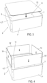
- FIG. 3 and 4 taken, in which the insertion of various inserts into the interior area 11 of the support structure 2 is illustrated.
- the inserts form the lining 29, which defines the trough-shaped cavity 25 of the transport trough 1.
- a base plate 13 is placed on the front floor surface 5 and several frame plates 14, 14' are placed adjacent to the frame sections 7, 7' of the inner frame surface 9.
- Figures 3 and 4 The insertion process is illustrated by arrows.
- the base plate 13 rests freely on the base 3.
- the frame plates 14, 14' are clamped against the frame 4, which will be described in more detail below.
- the base plate 13 and the frame plates 14, 14' are each designed here, for example, as flat plates that have no perforations. It would also be conceivable for the base plate 13 to be constructed in several parts, for example, composed of several strips.
- Figure 5 the transport tray 1 is shown in an intermediate state of assembly in a perspective view obliquely from above.
- Figure 5 illustrates in particular the fastening of the frame plates 14, 14' to the frame 4.
- corner pieces 15 are provided, which are placed in the area of the corner sections 8 on the edge areas 17, 17' of two immediately adjacent frame plates 14, 14'. The placing of the corner pieces 15 on the corner sections 8 is shown in Figure 5 illustrated by arrows.
- the corner pieces 15 are fastened to the frame 4 by means of threaded screws 16, which are guided from the outside through the openings 12 of the corner sections 8 of the frame 4 and screwed to the corner pieces 15.
- the corner pieces 15 are For this purpose, they are provided with blind-ended (non-penetrating) blind holes, each of which has a thread for screwing with the threaded screws 16.
- the blind holes and their threads are not shown in detail in the figures.
- blind holes represent a particularly good technical solution. It would also be conceivable to provide through holes instead of blind holes (which is more cost-effective), in which case the threaded screws 16 would then be secured with nuts.
- the disadvantage of this solution is that the nuts protrude into the trough-shaped cavity 25 of the transport trough 1, as they are exposed to the corrosive attack of chemically aggressive substances. To avoid this, it would be conceivable to provide a recess for each threaded screw 16 in the corner part 15, which accommodates the threaded screw 16 and the associated nut. In general, it is advantageous if no components not belonging to the lining, such as the threaded screws 16, protrude into the trough-shaped cavity 25.
- the frame plates 14, 14' are clamped against the inner frame surface 9 by the corner pieces 15.
- the base plate 13 is not attached to the floor 3, but rests freely on it. However, the base plate 13 can be fixed perpendicular to the floor 3 by means of a clamping by the frame plates 14, 14'.
- the fully assembled transport tray 1 is in Figure 1 shown.
- FIG 6 A horizontal section (parallel to the floor 3) of the fully assembled transport tray 1 is shown. A corner area of the transport tray 1 is marked by the dashed circle A. The marked corner area A of the transport tray 1 of Figure 6 is in Figure 7 shown in a greatly enlarged view.
- the corner part 15 overlaps the respective edge regions 17, 17' of the adjacent frame panels 14, 14'.
- the corner part 15 is provided on both sides with grooves 18, 18', in which the edge regions 17, 17' of the frame panels 14, 14' are received.
- the grooves 18, 18' each have a strip-shaped projection 19, 19', which overlaps the corresponding edge region 17, 17' of the frame panels 14, 14'.
- edge areas 17, 17' of the frame plates 14, 14' are each accommodated with play in the corresponding groove 18, 18', ie they fill the grooves 18, 18' not completely sufficient. Accordingly, there is a free space ("free space") between a respective edge region 17, 17' of the frame plates 14, 14' and the corner part 15 within the grooves 18, 18'.
- These free spaces 20, 20' are formed in the circumferential direction of the frame 4 (i.e., in the plane of the frame plates 14, 14' and in the circumferential direction of the frame 4).
- the frame plates 14, 14' thus each have a free space in at least two orthogonal directions relative to their plate plane, so that thermally induced expansion of the frame plates 14, 14' is possible without hindrance. In other words, the frame plates 14, 14' are each received in the grooves 18, 18' with sufficient play, so that thermal expansion of the frame slats 14, 14' in the plate planes is possible.
- the width of the free spaces 20, 20' measured in the circumferential direction of the frame 4 is only large enough to allow thermal expansion of the frame plates 14 without obstruction, while preventing excessive contamination.
- the width of the free spaces 20, 20' is preferably a maximum of 2.5 mm.
- Figure 8 a sectional view of the transport tray 1 perpendicular to the plane of the base 3 and in Figure 9 an enlarged sectional view according to the Figure 8 marked area B.
- the base plate 13 is also accommodated within the inner region 11 of the support structure 2 with play, whereby a circumferential gap 21 (i.e., a free space) remains between the base plate 13 and the frame sections 7, 7'.
- the base plate 13 thus has, with respect to its plate plane, a free space in at least two orthogonal directions (here even circumferentially), so that a thermally induced expansion of the base plate 13 is not hindered.
- the thermally induced expansion of the base plate 13 is in Figure 8 shown schematically by arrows. In other words, the base plate 13 is supported by the support structure 2 with sufficient clearance to allow for thermal expansion in the plane of the plate.
- the frame plates 14, 14' each have a width T measured perpendicular to the gap 21 (see Figure 9 ), which is larger than the width of the gap 21, so that the frame plates 14, 14' cannot penetrate into the gap 21, but rather rest on the base plate 13.
- the width T of the frame plates 14, 14' is measured parallel to the plane of the floor 3 and is the shortest dimension perpendicular through the frame plates 14, 14'.
- the frame plates 14, 14' resting on the floor plate 13 allow the floor plate 13 to be fixed in a direction perpendicular to the floor 3, whereby the thermal expansion of the floor plate 13 in the plate plane is not impaired.
- the interior area 11 of the support structure 2 is completely lined by the base plate 13 and the frame plates 14, 14', as well as the corner pieces 15, i.e., the base plate 13 and the frame plates 14, 14', as well as the corner pieces 15, together form a complete lining 29 (i.e., wall) of a trough-shaped cavity 25 of the transport trough 1.
- the cavity 25 serves to accommodate starting materials that are to be converted into a chemical product by heating in a furnace, e.g., a continuous furnace.
- the transport trough 1 is placed on the rear floor surface 6 in the furnace, in particular, transported through the furnace.
- the lining 29 can be removed from the support structure 2 without causing damage.
- the transport tray 1 can solve the problems mentioned above in connection with the required high thermal shock resistance combined with good corrosion resistance of the transport tray 1.
- the support structure 2 and the lining 29 can be manufactured from different materials according to their function.
- the support structure 2 is well protected against corrosion by the lining 29, so that the material of the support structure 2 can be selected essentially with regard to its thermal shock resistance and strength.
- Corrosion resistance is of secondary importance for the support structure 2.
- the lining 29 must be highly resistant to corrosion and thermal shock, with the corrosion resistance being achieved through the special choice of material and the temperature resistance through the structural design of the lining 29.
- the thermal expansions of both the base plate 13 and also the frame plates 14, 14' in their respective plate planes is not hindered, so that no disadvantageous high mechanical stresses build up, which could ultimately lead to the breakage of the transport tray 1.
- the support structure 2 and the lining 29 of the support structure 2 advantageously consist of different materials, wherein the lining 29 preferably consists of a material which, with respect to the chemical conversion of the same product, is more corrosion-resistant than the material of the support structure 2.
- the support structure 2 is preferably made of a high-strength, thermal shock-resistant material with a relatively low material thickness and a relatively low weight.
- the support structure 2 preferably contains or consists of a material selected from R-SiC, N-SiC, S-SiC, Si-SiC, oxide-bonded SiC, or mixtures thereof.
- the support structure 2 can also be made of cordierite, mullite, or a cordierite/spinel/mullite mixture, for example. These are materials with high strength, low thermal expansion, and excellent thermal shock resistance. However, in the case of SiC, they have rather low corrosion resistance, which is harmless, however, since the support structure 2 is well protected against corrosion by the lining 29.
- the lining 29 preferably contains aluminum/magnesium spinel, yttrium oxide (Y 2 O 3 ), cerium oxide (CeO 2 ), hafnium oxide, aluminum oxide (Al 2 O 3 ), magnesium oxide (MgO), zirconium oxide (ZrO 2 ), or mixtures thereof, the content of these substances preferably being at least 80%, particularly preferably at least 90%.
- the lining 29 can also consist of these substances.
- Aluminum oxide that is as pure as possible, which is ideally densely fired, is a material with particularly good corrosion resistance, but rather low thermal shock resistance. These materials can be cast, pressed or produced using plasma or film casting processes.
- the frame plates 14, 14' and/or the base plate 13 each have a relatively thin wall thickness in the range of 1.5 mm to 5 mm and are designed, for example, in the form of a film.
- the support structure 2 can be used very frequently due to the good protection against corrosion provided by the lining 29 and its manufacture from at least one of the aforementioned materials with good thermal shock resistance.
- the service life of the support structure 2 can be more than 1,000 cycles.
- the lining 29 can be removed from the support structure 2 without causing damage and can therefore be easily replaced separately if it becomes corroded and easily reused. Since the material of the lining 29 can be specifically selected for corrosion resistance and the thermal shock resistance of the lining 29 is ensured by its structural design, the lining 29 can also be used for a very large number of firing cycles without having to be replaced.
- the base plate 13 and the frame plates 14, 14' can be made of different materials, with the base plate 13 advantageously being made of a material which, based on the chemical conversion of the same product, is more corrosion-resistant than the material of the frame plates 14, 14'.
- the base plate 13 preferably contains at least 80%, particularly preferably at least 90%, aluminum/magnesium spinel, yttrium oxide (Y 2 O 3 ), cerium oxide (CeO 2 ), hafnium oxide, aluminum oxide (Al 2 O 3 ), magnesium oxide (MgO), zirconium oxide (ZrO 2 ) or mixtures thereof.
- the base plate 13 can also be made of these materials.
- the base plate 13 can also have a coating containing one of these materials or mixtures thereof.
- the frame plates 14, 14' are made of a material selected from the group consisting of aluminum oxide, zirconium oxide, magnesium oxide, R-SiC, N-SiC, S-SiC, and Si-SiC, or mixtures thereof.
- the frame plates 14, 14' can also be made of cordierite or a cordierite/spinel/mullite mixture.
- the base plate 13 and the frame plates 14, 14' may also consist of the same material, which is preferably at least 80%, particularly preferably at least 90%, aluminum/magnesium spinel, yttrium oxide (Y 2 O 3 ), cerium oxide (CeO 2 ), hafnium oxide, aluminum oxide (Al 2 O 3 ), magnesium oxide (MgO), zirconium oxide (ZrO 2 ), or mixtures thereof.
- the base plate 13 and the frame plates 14, 14' may also have a coating containing one of these materials or mixtures thereof.
- the base plate 13 and the frame plates 14, 14', as well as the corner pieces 15, can be replaced separately.
- the base plate 13 can be replaced separately if it is more corroded than the frame plates 14, 14'. This can save costs and materials.
- the base plate 13 or the frame plates 14, 14' can be easily cleaned, for example by sandblasting. It would also be conceivable to form the base plate 13 in multiple parts, for example from strips. In this case, separate strip replacement would also be possible.
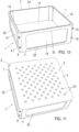
- Figure 10 shows a further embodiment of the transport tray 1 in a perspective view obliquely from above
- Figure 11 shows the underside of the transport tray 1.
- the frame sections 7, 7' of the frame 4 of the support structure 2 are each provided with a recess 22, which is approximately rectangular in shape here, for example.
- the recesses 22 each extend over a large part (preferably at least 50%) of the area of the associated frame section 7, 7'.
- the base 3 of the support structure 2 (but not the base plate 13) is also provided with a plurality of holes 23.
- the recesses 22 and the holes 23 allow the weight of the transport tray 1 to be reduced. Furthermore, material and costs for the support structure 2 can be saved.
- a further advantage results from the improved heat transfer to the firing material.
- this advantageously reduces the disadvantage of relatively poor thermal conductivity of, for example, aluminum oxide-rich materials.
- the frame plates 14, 14' advantageously have a relatively thin wall thickness.
- the recesses 22 have a large extent with respect to onto the surface of the corresponding frame section 7, 7'. The heat can thus be transferred to the firing material without any significant delay.
- the recesses 22 of the frame sections 7, 7' are here, for example, each completely surrounded by the material of the associated frame section 7, 7, i.e., the recesses 22 are each formed internally.
- This has the advantage that a frame web 30 is present at the opening of the trough-shaped cavity 25 of the transport trough 1, which serves as an abutting edge for the frame plates 14, 14' and protects them from damage, e.g., when filling, emptying, and cleaning the transport trough 1, and generally during any handling outside of the firing process.
- frame plates 14, 14' and a base plate 13 with low strength and high porosity can be used here. These enable increased oxygen and energy transport to the fuel.
- Figure 12 shows the transport tray 1 in a perspective view from above
- Figure 11 shows a (vertical) section of the transport trough 1 perpendicular through the base 3.
- wedge-shaped corner strips 24 are provided at the transition between the frame plates 14, 14' and the base plate 13.
- the corner strips 24 can be used to seal the area of the respective abutting edge between the base plate 14 and the frame plates 14, 14', so that material is reliably and safely prevented from entering and reaching the support structure 2.
- the corner strips 24 form part of the lining 29 of the transport trough 1 and thus of the trough-shaped cavity 25 of the transport trough 1.
- the corner strips 24 are geometrically well adapted to the transition.
- the corner strips 24 are advantageously made of the same material as the base plate 13 and the frame plates 14, 14'.
- the corner strips 24 preferably contain at least 80%, particularly preferably at least 90%, of aluminum/magnesium spinel, yttrium oxide (Y 2 O 3 ), cerium oxide (CeO 2 ), hafnium oxide, aluminum oxide (Al 2 O 3 ), magnesium oxide (MgO), zirconium oxide (ZrO 2 ), or mixtures thereof.
- the corner strips 24 can also be made of these materials.
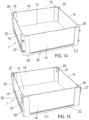
- Figures 14 and 15 further embodiments of the transport tray 1 according to the invention are illustrated.
- Figure 14 shows the transport tray 1 in a perspective view from above.
- Figure 15 is a variant of the embodiment of Figure 14 equally shown in a perspective view from above.
- the frame sections 7, 7' of the frame 4 of the support structure 2 are each provided with a recess 22, which extends over such an area that only corner pillars 26 of the frame 4 remain, to which the corner parts 15 for fastening the frame plates 14, 14' are screwed.
- the support structure 2 in this embodiment is composed of the corner pillars 26 and the floor 3, frame webs 30 as in Figure 10 are missing.
- the frame 4 is thus an open frame and consists only of the corner pillars 26.
- the frame sections 7, 7' are largely (more than 80%) recessed.
- the corner pillars 26 are each composed of the corner section 8 and a small area of the adjacent frame section 7, 7'. This measure allows for significant savings in weight, material, and costs. Furthermore, the heat transfer to the firing material can be further improved.
- the threaded screws 16 are replaced by spring-elastic clamps 27, which serve to attach the corner pieces 15 to the corner pillars 26.
- the clamps 27 are attached from above to the corner pieces 15 and the corner pillars 26.
- the clamps 27 are made of a ceramic material with high thermal shock resistance.
- the clamps 27 are made of specially stabilized zirconium oxide.
- the clamps 27 here, for example, have a U-shape and can be easily attached or removed to firmly connect or detach the corner pieces 15 and the frame 4.
- the clamps 27 are typically provided with a device (nose) so that they remain permanently locked, which is not shown in detail. Clamping at the four corner sections 8 ensures a permanently secure connection between the frame 4 and the frame panels 14, 14'.
- Figures 16 and 17 a further embodiment of the transport tray 1 according to the invention is illustrated, wherein Figure 16 a sectional view perpendicular to the plane of the soil 3 and Figure 17 shows an enlarged sectional view according to the area C. This embodiment forms the embodiments of Figure 14 and Figure 15 away.
- the floor slab 13 extends in the area of the frame slabs 14, 14' beyond the frame slabs 14, 14', with the frame slabs 14, 14' each resting on the floor slab 13 with their entire width.
- the floor slab 13 is thus larger than the area defined by the frame slabs 14, 14' and has a projection 28 relative to them.
- This design also offers the advantage that the thermal expansion of the floor slab 13 in its plane is not hindered, but the floor slab 13 is firmly clamped against the floor 3.
- the fastening of the frame slabs 14, 14' to the corner pillars 26 can be carried out as shown in the Figures 14 and 15 so that their representation in Figure 16 was waived.
- FIGs 18 and 19 A further embodiment of the transport tray 1 according to the invention is illustrated, which shows the design of Figure 14 trained.
- Figure 18 shows only the support structure 2 of the transport tray 1 in a perspective view obliquely from above.
- Figure 19 shows the underside of the complete transport tray 1.
- the support structure 2 is composed of the base 3 and the corner pillars 26.
- the base 3 of the support structure 2 is provided with a plurality of holes 23, for example, diamond-shaped holes 23.
- the holes 23 are arranged in a regular manner, for example, in the form of a grid. This measure allows the weight, material, and costs of the support structure 2 to be further reduced.
- the front base surface 5 is provided with a plurality of parallel support webs 28, which serve to support the base plate 13.
- the invention provides an improved transport trough for the transport and heating of chemical substances.
- the transport trough advantageously has high corrosion resistance and, at the same time, good resistance to thermal shock.
- the good resistance to thermal shock is achieved through the choice of material for the support structure and the geometric design of the lining of the trough-shaped cavity of the transport trough.
- High corrosion resistance can be achieved through the choice of material for the lining.
- the materials for the support structure and the lining can be specifically tailored to their essential functions.
- the material for the lining can advantageously be selected so that the purity or quality of the firing material is not compromised.
- the transport tank can thus be used for a large number of firing cycles, which is significantly higher than the number of firing cycles of conventional transport tanks.
- the overall lower costs for the transport tanks can reduce the costs of large-scale production of chemical products. This is particularly true for the production of active cathode materials for lithium-ion batteries. Likewise, the hazardous waste generated by corrosion-damaged transport tanks can be significantly reduced.
Landscapes
- Engineering & Computer Science (AREA)
- Mechanical Engineering (AREA)
- General Engineering & Computer Science (AREA)
- Manufacturing & Machinery (AREA)
- Chemical & Material Sciences (AREA)
- Chemical Kinetics & Catalysis (AREA)
- Electrochemistry (AREA)
- General Chemical & Material Sciences (AREA)
- Furnace Charging Or Discharging (AREA)
- Heat Treatments In General, Especially Conveying And Cooling (AREA)
Claims (15)
- Plateau de transport (1) pour transporter et chauffer des substances chimiques, qui comprend une structure de support monobloc (2) avec une base (3) et un cadre (4) relié de manière fixe, dans lequel la structure de support (2) supporte un revêtement (29) d'une cavité en forme de plateau (25) pour loger les substances chimiques, dans lequel le revêtement (29) comprend une plaque de base (13) reposant sur la base (3) et plusieurs plaques de cadre (14, 14') serrées contre le cadre (4), dans lequel le revêtement (29) est soutenu par la structure de support (2) de telle sorte que les dilatations thermiques de la plaque de base (13) et des plaques de cadre (14, 14') dans leurs plans ne sont pas entravées,dans lequel les plaques de cadre (14, 14') sont fixées au cadre (4) par des bandes de serrage (15), dans lequel les bandes de serrage (15) ont chacune au moins une rainure (18, 18') pour loger une zone de bord (17, 17') d'une plaque de cadre adjacente (14, 14'), dans lequel la zone de bord (17, 17') est logée avec jeu dans la rainure (18, 18') de la bande de serrage (15), etla plaque de base (13) repose sur la base (3) de la structure de support (2) et est disposée avec du jeu dans le cadre (4) de la structure de support (2) et les autres composants (14, 14') du revêtement (29).
- Plateau de transport (1) selon la revendication 1, dans lequel le cadre (4) de la structure de support (2) est un cadre périmétrique.
- Plateau de transport (1) selon la revendication 2, dans lequel le cadre périmétrique (4) de la structure de support (2) comprend des sections de cadre en forme de plaque (7, 7'), dans lesquelles au moins une section de cadre en forme de plaque (7, 7') présente au moins une découpe (22).
- Plateau de transport (1) selon la revendication 3, dans lequel l'au moins une découpe (22) est une découpe interne.
- Plateau de transport (1) selon la revendication 3, dans lequel l'au moins une découpe (22) est une découpe de bord.
- Plateau de transport (1) selon l'une des revendications 1 à 5, dans lequel la base (3) de la structure de support (2) comporte plusieurs trous (23).
- Plateau de transport (1) selon l'une des revendications 1 à 5, dans lequel le cadre (4) de la structure de support consiste en une pluralité de piliers (26).
- Plateau de transport (1) selon l'une des revendications 1 à 7, dans lequel les plaques de cadre (14, 14') sont dans chaque cas assises sur la plaque de base (13).
- Plateau de transport (1) selon la revendication 8, qui comporte des bandes d'angle en forme de coin (24) pour couvrir les bords aboutés respectifs entre les plaques de cadre (14, 14') et la plaque de base (13).
- Plateau de transport (1) selon l'une des revendications 1 à 9, dans lequel la plaque de base (13) dépasse les plaques de cadre (14, 14') dans le plan de la plaque.
- Plateau de transport (1) selon l'une des revendications 1 à 10, dans lequel le matériau du revêtement (29) est plus résistant à la corrosion que le matériau de la structure de support (2), sur la base de la réaction chimique du même produit.
- Plateau de transport (1) selon l'une des revendications 1 à 11, dans lequel la structure de support (2) contient un matériau choisi parmi la cordiérite, la mullite, un mélange cordiérite/spinel/mullite, R-SiC, N-SiC, S-SiC, Si-SiC, Si-C lié par oxydation, ou leurs mélanges, et/ou dans lequel le revêtement (29) est plus résistant à la corrosion que le matériau de la structure de support (2), sur la base d'une réaction chimique du même produit, ou leurs mélanges, et/ou dans lequel le revêtement (29) contient au moins 80 % de spinelle d'aluminium/magnésium, d'oxyde d'yttrium (Y2O3), d'oxyde de cérium (CeO2), d'oxyde d'hafnium, d'oxyde d'aluminium (Al2O3), d'oxyde de magnésium (MgO), d'oxyde de zirconium (ZrO2), ou de leurs mélanges.
- Plateau de transport (1) selon l'une des revendications 1 à 12, dans lequel la plaque de base (13) a un revêtement comprenant au moins 80% de spinelle d'aluminium/magnésium, d'oxyde d'yttrium (Y2O3), d'oxyde de cérium (CeO2), d'oxyde d'hafnium, d'oxyde d'aluminium (Al2O3), d'oxyde de magnésium (MgO), d'oxyde de zirconium (ZrO2), ou des mélanges de ceux-ci.
- Plateau de transport (1) selon l'une des revendications 1 à 13, dans lequel la plaque de base (13) et les plaques de cadre (14, 14') ont un revêtement comprenant au moins 80% de spinelle d'aluminium/magnésium, d'oxyde d'yttrium (Y2O3), d'oxyde de cérium (CeO2), d'oxyde de hafnium, d'oxyde d'aluminium ((Al2O3), d'oxyde de magnésium (MgO), d'oxyde de zirconium (ZrO2), ou des mélanges de ceux-ci.
- Utilisation du plateau de transport (1) selon l'une des revendications 1 à 14 pour produire un matériau de cathode pour une batterie lithium-ion.
Applications Claiming Priority (2)
| Application Number | Priority Date | Filing Date | Title |
|---|---|---|---|
| DE102020000510.1A DE102020000510B4 (de) | 2020-01-28 | 2020-01-28 | Transportwanne zum Transportieren und Erhitzen chemischer Substanzen |
| PCT/EP2021/051810 WO2021151917A1 (fr) | 2020-01-28 | 2021-01-27 | Cuve de transport permettant de transporter et de chauffer des substances chimiques |
Publications (3)
| Publication Number | Publication Date |
|---|---|
| EP4097410A1 EP4097410A1 (fr) | 2022-12-07 |
| EP4097410C0 EP4097410C0 (fr) | 2025-05-21 |
| EP4097410B1 true EP4097410B1 (fr) | 2025-05-21 |
Family
ID=74561853
Family Applications (1)
| Application Number | Title | Priority Date | Filing Date |
|---|---|---|---|
| EP21703842.1A Active EP4097410B1 (fr) | 2020-01-28 | 2021-01-27 | Cuve de transport permettant de transporter et de chauffer des substances chimiques |
Country Status (7)
| Country | Link |
|---|---|
| US (1) | US12270608B2 (fr) |
| EP (1) | EP4097410B1 (fr) |
| JP (1) | JP7356598B2 (fr) |
| KR (1) | KR102775120B1 (fr) |
| CN (1) | CN115038923B (fr) |
| DE (1) | DE102020000510B4 (fr) |
| WO (1) | WO2021151917A1 (fr) |
Families Citing this family (10)
| Publication number | Priority date | Publication date | Assignee | Title |
|---|---|---|---|---|
| DE102018129272A1 (de) * | 2018-11-21 | 2020-05-28 | Saint-Gobain Industriekeramik Rödental GmbH | Transportwanne für Durchlaufofen |
| WO2023062148A1 (fr) * | 2021-10-13 | 2023-04-20 | Saint-Gobain Industriekeramik Rödental GmbH | Cadre en plusieurs parties pour cuve de transport en céramique |
| FR3131295B1 (fr) | 2021-12-23 | 2023-12-29 | Saint Gobain Ct Recherches | support de cuisson de poudre alcaline avec revêtement de porosité contrôlée |
| US20250070822A1 (en) * | 2023-08-21 | 2025-02-27 | BCS Access Systems US, LLC | Near field communication system |
| CN121318511A (zh) | 2024-07-12 | 2026-01-13 | 欧洲技术研究圣戈班中心 | 具有氮化物基体的陶瓷焙烧载具 |
| FR3164460A1 (fr) | 2024-07-12 | 2026-01-16 | Saint-Gobain Centre De Recherches Et D'etudes Europeen | Support de cuisson de carbure de silicium fritté avec phase liante de corindon |
| FR3164459A1 (fr) | 2024-07-12 | 2026-01-16 | Saint-Gobain Centre De Recherches Et D'etudes Europeen | Support de cuisson céramique avec matrice de nitrure |
| CN121318510A (zh) | 2024-07-12 | 2026-01-13 | 欧洲技术研究圣戈班中心 | 具有刚玉粘结相的用于烧结碳化硅的焙烧载具 |
| FR3165693A3 (fr) | 2024-08-22 | 2026-02-27 | Saint-Gobain Centre De Recherches Et D'etudes Europeen | Support de cuisson comprenant un revêtement de grains de borocarbonitrure et une phase liante phosphatée |
| WO2026041719A1 (fr) | 2024-08-22 | 2026-02-26 | Saint-Gobain Centre De Recherches Et D'etudes Europeen | Support de cuisson comprenant un revêtement de grains de borocarbonitrure et une phase liante phosphatee |
Family Cites Families (26)
| Publication number | Priority date | Publication date | Assignee | Title |
|---|---|---|---|---|
| US2297286A (en) | 1940-01-30 | 1942-09-29 | Austin R Book | Sagger |
| US3988107A (en) * | 1975-08-12 | 1976-10-26 | Ferro Corporation | Sagger construction |
| DE2705121A1 (de) * | 1977-02-08 | 1978-08-17 | Zytan Thermochem Verfahren | Anlage fuer die herstellung von formkoerpern aus granulaten keramischer materialien |
| US4330269A (en) * | 1981-01-14 | 1982-05-18 | Chu Shieh C | Refractory sagger |
| DE9004458U1 (de) | 1990-04-19 | 1990-06-28 | Schunk Kohlenstofftechnik GmbH, 6301 Heuchelheim | Glühbehälter für Wärmebehandlung von Füllgut |
| JP2002029857A (ja) * | 2000-05-10 | 2002-01-29 | Mitsubishi Materials Corp | 小型セラミック電子部品焼成用トレイ |
| DE502004004737D1 (de) | 2003-06-13 | 2007-10-04 | Schunk Kohlenstofftechnik Gmbh | Träger für Bauteile |
| DE102005024957A1 (de) | 2005-05-31 | 2006-12-07 | Saint-Gobain Industriekeramik Rödental GmbH | Mehrteiliger, dünnwandiger Tiegel mit Einlage aus Quarzglasgewebe oder Quarzglasfilz zum Abkühlen von Si-Schmelzen |
| US20090208400A1 (en) * | 2006-06-23 | 2009-08-20 | Stein Julsrud | Method and crucible for direct solidification of semiconductor grade multi-crystalline silicon ingots |
| JPWO2012133525A1 (ja) * | 2011-03-30 | 2014-07-28 | 京セラ株式会社 | 焼成用部材およびこれを用いた焼成用容器ならびに正極材料の製造方法 |
| JP5341124B2 (ja) * | 2011-03-30 | 2013-11-13 | 東京窯業株式会社 | リチウムイオン電池用正極活物質用熱処理容器 |
| DE102011052016A1 (de) | 2011-07-21 | 2013-01-24 | Deutsches Zentrum für Luft- und Raumfahrt e.V. | Bausatz für einen Schmelztiegel, Schmelztiegel und Verfahren zur Herstellung eines Schmelztiegels |
| CN103827048B (zh) * | 2011-08-05 | 2017-05-10 | 科卢斯博知识产权有限公司 | 坩埚材料 |
| KR101402539B1 (ko) * | 2012-04-18 | 2014-05-30 | 삼성에스디아이 주식회사 | 소성용기 |
| JP5474126B2 (ja) * | 2012-05-02 | 2014-04-16 | 東京窯業株式会社 | リチウムイオン電池用正極活物質用熱処理容器 |
| KR200468934Y1 (ko) * | 2013-04-24 | 2013-09-10 | 이철휘 | 다단 적재용 박스형 새거 |
| DE202014100849U1 (de) * | 2014-02-25 | 2014-05-12 | Imerys Kiln Furniture Hungary | Brennkapselanordnung |
| JP6396938B2 (ja) * | 2016-03-30 | 2018-09-26 | 東京窯業株式会社 | リチウム電池の正極活物質用熱処理容器 |
| KR101988736B1 (ko) * | 2017-09-28 | 2019-06-12 | 주식회사 포스코 | 이차전지 활물질 소성용 내화갑 및 이를 이용한 이차전지 활물질 제조방법 |
| CN107883774A (zh) * | 2017-11-22 | 2018-04-06 | 江门市科恒实业股份有限公司 | 一种锂离子电池正极材料高温反应用匣钵 |
| CN108302942A (zh) * | 2018-01-08 | 2018-07-20 | 朱性宇 | 锂电池电极材料制备用匣钵、该匣钵的保护层以及匣钵的制备方法 |
| JP2019123647A (ja) * | 2018-01-17 | 2019-07-25 | 日本碍子株式会社 | セラミックス焼成体の製造方法 |
| DE102018115771A1 (de) * | 2018-06-29 | 2020-01-02 | Saint-Gobain Industriekeramik Rödental GmbH | Kapselartige Aufnahme, insbesondere Kapsel zum Brennen von pulverförmigem Kathoden-Material für Lithium-Ionen-Akkus sowie Mischung hierfür |
| DE102018129272A1 (de) * | 2018-11-21 | 2020-05-28 | Saint-Gobain Industriekeramik Rödental GmbH | Transportwanne für Durchlaufofen |
| KR102501948B1 (ko) * | 2020-12-18 | 2023-02-21 | 포스코홀딩스 주식회사 | 이차 전지의 수직형 양극재 소성 장치 |
| DE202021004154U1 (de) * | 2021-10-13 | 2022-11-03 | Saint-Gobain Industriekeramik Rödental GmbH | Mehrteiliger Rahmen für keramische Transportwanne |
-
2020
- 2020-01-28 DE DE102020000510.1A patent/DE102020000510B4/de active Active
-
2021
- 2021-01-27 KR KR1020227028827A patent/KR102775120B1/ko active Active
- 2021-01-27 EP EP21703842.1A patent/EP4097410B1/fr active Active
- 2021-01-27 JP JP2022545869A patent/JP7356598B2/ja active Active
- 2021-01-27 WO PCT/EP2021/051810 patent/WO2021151917A1/fr not_active Ceased
- 2021-01-27 CN CN202180011475.9A patent/CN115038923B/zh active Active
- 2021-01-27 US US17/795,726 patent/US12270608B2/en active Active
Also Published As
| Publication number | Publication date |
|---|---|
| JP7356598B2 (ja) | 2023-10-04 |
| DE102020000510A1 (de) | 2021-07-29 |
| EP4097410A1 (fr) | 2022-12-07 |
| CN115038923A (zh) | 2022-09-09 |
| DE102020000510B4 (de) | 2026-01-15 |
| EP4097410C0 (fr) | 2025-05-21 |
| KR102775120B1 (ko) | 2025-02-28 |
| WO2021151917A1 (fr) | 2021-08-05 |
| US12270608B2 (en) | 2025-04-08 |
| JP2023511457A (ja) | 2023-03-17 |
| CN115038923B (zh) | 2026-02-24 |
| US20230070101A1 (en) | 2023-03-09 |
| KR20220129618A (ko) | 2022-09-23 |
Similar Documents
| Publication | Publication Date | Title |
|---|---|---|
| EP4097410B1 (fr) | Cuve de transport permettant de transporter et de chauffer des substances chimiques | |
| EP4061971B1 (fr) | Plateau de transport permettant de transporter et de chauffer des substances chimiques | |
| DE202009001817U1 (de) | Substratträger zur Halterung einer Vielzahl von Solarzellenwafern | |
| DE102009015236B4 (de) | Tiegel und seine Verwendung | |
| EP2935152B1 (fr) | Dispositif de protection thermique | |
| DE2638990B2 (de) | Fluiddurchströmtes hohlplattenförmiges Kühlelement | |
| DE2430191C2 (de) | Wärmedämmende Abdeckung eines Verschlußdeckels eines Kernreaktorbehälters | |
| DE102010046530B4 (de) | Akkumulatormodul | |
| WO2006058629A1 (fr) | Element ecran thermique, procede et moule pour sa fabrication, revetement a gaz chaud et chambre de combustion | |
| EP2432610B1 (fr) | Dispositif de solidification dirigée de métal fondu | |
| DE202014100849U1 (de) | Brennkapselanordnung | |
| DE102011082628B4 (de) | Vorrichtung und Verfahren zur Herstellung von Silizium-Blöcken | |
| DE2731908C2 (de) | Verfahren und Vorrichtung zum Herstellen von Aluminium | |
| DE2756756C2 (de) | Schutzmanschette | |
| CH615463A5 (fr) | ||
| DE102008011508A1 (de) | Energiespeicher sowie Verfahren zur Herstellung des Energiespeichers | |
| DE2707437A1 (de) | Pyrometallurgisches system | |
| EP3350358B1 (fr) | Fond servant de cathode destiné à la fabrication d'aluminium | |
| DE2911582C2 (fr) | ||
| DE1092613B (de) | Stranggiesskokille | |
| WO2011023164A1 (fr) | Dispositif pour refroidir des préparations pathologiques/histologiques | |
| DE4435690C1 (de) | Brennhilfsmittelsystem | |
| EP2733225A1 (fr) | Agencement d'élément de refroidissement | |
| DE102023005201A1 (de) | Batterieformrahmen einer Traktionsbatterie eines Kraftfahrzeugs sowie entsprechende Traktionsbatterie | |
| DE809108C (de) | Zelle fuer Schmelzflusselektrolyse |
Legal Events
| Date | Code | Title | Description |
|---|---|---|---|
| STAA | Information on the status of an ep patent application or granted ep patent |
Free format text: STATUS: UNKNOWN |
|
| STAA | Information on the status of an ep patent application or granted ep patent |
Free format text: STATUS: THE INTERNATIONAL PUBLICATION HAS BEEN MADE |
|
| PUAI | Public reference made under article 153(3) epc to a published international application that has entered the european phase |
Free format text: ORIGINAL CODE: 0009012 |
|
| STAA | Information on the status of an ep patent application or granted ep patent |
Free format text: STATUS: REQUEST FOR EXAMINATION WAS MADE |
|
| 17P | Request for examination filed |
Effective date: 20220623 |
|
| AK | Designated contracting states |
Kind code of ref document: A1 Designated state(s): AL AT BE BG CH CY CZ DE DK EE ES FI FR GB GR HR HU IE IS IT LI LT LU LV MC MK MT NL NO PL PT RO RS SE SI SK SM TR |
|
| DAV | Request for validation of the european patent (deleted) | ||
| DAX | Request for extension of the european patent (deleted) | ||
| STAA | Information on the status of an ep patent application or granted ep patent |
Free format text: STATUS: EXAMINATION IS IN PROGRESS |
|
| 17Q | First examination report despatched |
Effective date: 20231113 |
|
| GRAP | Despatch of communication of intention to grant a patent |
Free format text: ORIGINAL CODE: EPIDOSNIGR1 |
|
| RIC1 | Information provided on ipc code assigned before grant |
Ipc: F27D 5/00 20060101AFI20240527BHEP |
|
| STAA | Information on the status of an ep patent application or granted ep patent |
Free format text: STATUS: GRANT OF PATENT IS INTENDED |
|
| INTG | Intention to grant announced |
Effective date: 20240704 |
|
| GRAS | Grant fee paid |
Free format text: ORIGINAL CODE: EPIDOSNIGR3 |
|
| GRAJ | Information related to disapproval of communication of intention to grant by the applicant or resumption of examination proceedings by the epo deleted |
Free format text: ORIGINAL CODE: EPIDOSDIGR1 |
|
| GRAL | Information related to payment of fee for publishing/printing deleted |
Free format text: ORIGINAL CODE: EPIDOSDIGR3 |
|
| STAA | Information on the status of an ep patent application or granted ep patent |
Free format text: STATUS: EXAMINATION IS IN PROGRESS |
|
| INTC | Intention to grant announced (deleted) | ||
| GRAP | Despatch of communication of intention to grant a patent |
Free format text: ORIGINAL CODE: EPIDOSNIGR1 |
|
| STAA | Information on the status of an ep patent application or granted ep patent |
Free format text: STATUS: GRANT OF PATENT IS INTENDED |
|
| INTG | Intention to grant announced |
Effective date: 20241216 |
|
| GRAA | (expected) grant |
Free format text: ORIGINAL CODE: 0009210 |
|
| STAA | Information on the status of an ep patent application or granted ep patent |
Free format text: STATUS: THE PATENT HAS BEEN GRANTED |
|
| AK | Designated contracting states |
Kind code of ref document: B1 Designated state(s): AL AT BE BG CH CY CZ DE DK EE ES FI FR GB GR HR HU IE IS IT LI LT LU LV MC MK MT NL NO PL PT RO RS SE SI SK SM TR |
|
| REG | Reference to a national code |
Ref country code: GB Ref legal event code: FG4D Free format text: NOT ENGLISH |
|
| REG | Reference to a national code |
Ref country code: CH Ref legal event code: EP |
|
| REG | Reference to a national code |
Ref country code: DE Ref legal event code: R096 Ref document number: 502021007528 Country of ref document: DE |
|
| REG | Reference to a national code |
Ref country code: IE Ref legal event code: FG4D Free format text: LANGUAGE OF EP DOCUMENT: GERMAN |
|
| U01 | Request for unitary effect filed |
Effective date: 20250617 |
|
| U07 | Unitary effect registered |
Designated state(s): AT BE BG DE DK EE FI FR IT LT LU LV MT NL PT RO SE SI Effective date: 20250627 |
|
| PG25 | Lapsed in a contracting state [announced via postgrant information from national office to epo] |
Ref country code: ES Free format text: LAPSE BECAUSE OF FAILURE TO SUBMIT A TRANSLATION OF THE DESCRIPTION OR TO PAY THE FEE WITHIN THE PRESCRIBED TIME-LIMIT Effective date: 20250521 |
|
| PG25 | Lapsed in a contracting state [announced via postgrant information from national office to epo] |
Ref country code: GR Free format text: LAPSE BECAUSE OF FAILURE TO SUBMIT A TRANSLATION OF THE DESCRIPTION OR TO PAY THE FEE WITHIN THE PRESCRIBED TIME-LIMIT Effective date: 20250822 Ref country code: NO Free format text: LAPSE BECAUSE OF FAILURE TO SUBMIT A TRANSLATION OF THE DESCRIPTION OR TO PAY THE FEE WITHIN THE PRESCRIBED TIME-LIMIT Effective date: 20250821 |
|
| PG25 | Lapsed in a contracting state [announced via postgrant information from national office to epo] |
Ref country code: PL Free format text: LAPSE BECAUSE OF FAILURE TO SUBMIT A TRANSLATION OF THE DESCRIPTION OR TO PAY THE FEE WITHIN THE PRESCRIBED TIME-LIMIT Effective date: 20250521 |
|
| PG25 | Lapsed in a contracting state [announced via postgrant information from national office to epo] |
Ref country code: HR Free format text: LAPSE BECAUSE OF FAILURE TO SUBMIT A TRANSLATION OF THE DESCRIPTION OR TO PAY THE FEE WITHIN THE PRESCRIBED TIME-LIMIT Effective date: 20250521 |
|
| PG25 | Lapsed in a contracting state [announced via postgrant information from national office to epo] |
Ref country code: RS Free format text: LAPSE BECAUSE OF FAILURE TO SUBMIT A TRANSLATION OF THE DESCRIPTION OR TO PAY THE FEE WITHIN THE PRESCRIBED TIME-LIMIT Effective date: 20250821 |
|
| PG25 | Lapsed in a contracting state [announced via postgrant information from national office to epo] |
Ref country code: IS Free format text: LAPSE BECAUSE OF FAILURE TO SUBMIT A TRANSLATION OF THE DESCRIPTION OR TO PAY THE FEE WITHIN THE PRESCRIBED TIME-LIMIT Effective date: 20250921 |
|
| PG25 | Lapsed in a contracting state [announced via postgrant information from national office to epo] |
Ref country code: SM Free format text: LAPSE BECAUSE OF FAILURE TO SUBMIT A TRANSLATION OF THE DESCRIPTION OR TO PAY THE FEE WITHIN THE PRESCRIBED TIME-LIMIT Effective date: 20250521 |
|
| U20 | Renewal fee for the european patent with unitary effect paid |
Year of fee payment: 6 Effective date: 20251205 |
|
| PG25 | Lapsed in a contracting state [announced via postgrant information from national office to epo] |
Ref country code: CZ Free format text: LAPSE BECAUSE OF FAILURE TO SUBMIT A TRANSLATION OF THE DESCRIPTION OR TO PAY THE FEE WITHIN THE PRESCRIBED TIME-LIMIT Effective date: 20250521 |
|
| PG25 | Lapsed in a contracting state [announced via postgrant information from national office to epo] |
Ref country code: SK Free format text: LAPSE BECAUSE OF FAILURE TO SUBMIT A TRANSLATION OF THE DESCRIPTION OR TO PAY THE FEE WITHIN THE PRESCRIBED TIME-LIMIT Effective date: 20250521 |
|
| PLBE | No opposition filed within time limit |
Free format text: ORIGINAL CODE: 0009261 |
|
| STAA | Information on the status of an ep patent application or granted ep patent |
Free format text: STATUS: NO OPPOSITION FILED WITHIN TIME LIMIT |
|
| REG | Reference to a national code |
Ref country code: CH Ref legal event code: L10 Free format text: ST27 STATUS EVENT CODE: U-0-0-L10-L00 (AS PROVIDED BY THE NATIONAL OFFICE) Effective date: 20260402 |
|
| 26N | No opposition filed |
Effective date: 20260224 |