EP4062082B1 - Arretiersystem - Google Patents
Arretiersystem Download PDFInfo
- Publication number
- EP4062082B1 EP4062082B1 EP21732811.1A EP21732811A EP4062082B1 EP 4062082 B1 EP4062082 B1 EP 4062082B1 EP 21732811 A EP21732811 A EP 21732811A EP 4062082 B1 EP4062082 B1 EP 4062082B1
- Authority
- EP
- European Patent Office
- Prior art keywords
- cylinder
- inner sleeve
- locking system
- piston
- closing part
- Prior art date
- Legal status (The legal status is an assumption and is not a legal conclusion. Google has not performed a legal analysis and makes no representation as to the accuracy of the status listed.)
- Active
Links
Images



Classifications
-
- F—MECHANICAL ENGINEERING; LIGHTING; HEATING; WEAPONS; BLASTING
- F16—ENGINEERING ELEMENTS AND UNITS; GENERAL MEASURES FOR PRODUCING AND MAINTAINING EFFECTIVE FUNCTIONING OF MACHINES OR INSTALLATIONS; THERMAL INSULATION IN GENERAL
- F16F—SPRINGS; SHOCK-ABSORBERS; MEANS FOR DAMPING VIBRATION
- F16F9/00—Springs, vibration-dampers, shock-absorbers, or similarly-constructed movement-dampers using a fluid or the equivalent as damping medium
- F16F9/10—Springs, vibration-dampers, shock-absorbers, or similarly-constructed movement-dampers using a fluid or the equivalent as damping medium using liquid only; using a fluid of which the nature is immaterial
- F16F9/14—Devices with one or more members, e.g. pistons, vanes, moving to and fro in chambers and using throttling effect
- F16F9/16—Devices with one or more members, e.g. pistons, vanes, moving to and fro in chambers and using throttling effect involving only straight-line movement of the effective parts
- F16F9/18—Devices with one or more members, e.g. pistons, vanes, moving to and fro in chambers and using throttling effect involving only straight-line movement of the effective parts with a closed cylinder and a piston separating two or more working spaces therein
- F16F9/185—Bitubular units
-
- F—MECHANICAL ENGINEERING; LIGHTING; HEATING; WEAPONS; BLASTING
- F15—FLUID-PRESSURE ACTUATORS; HYDRAULICS OR PNEUMATICS IN GENERAL
- F15B—SYSTEMS ACTING BY MEANS OF FLUIDS IN GENERAL; FLUID-PRESSURE ACTUATORS, e.g. SERVOMOTORS; DETAILS OF FLUID-PRESSURE SYSTEMS, NOT OTHERWISE PROVIDED FOR
- F15B15/00—Fluid-actuated devices for displacing a member from one position to another; Gearing associated therewith
- F15B15/20—Other details, e.g. assembly with regulating devices
- F15B15/26—Locking mechanisms
-
- F—MECHANICAL ENGINEERING; LIGHTING; HEATING; WEAPONS; BLASTING
- F16—ENGINEERING ELEMENTS AND UNITS; GENERAL MEASURES FOR PRODUCING AND MAINTAINING EFFECTIVE FUNCTIONING OF MACHINES OR INSTALLATIONS; THERMAL INSULATION IN GENERAL
- F16F—SPRINGS; SHOCK-ABSORBERS; MEANS FOR DAMPING VIBRATION
- F16F9/00—Springs, vibration-dampers, shock-absorbers, or similarly-constructed movement-dampers using a fluid or the equivalent as damping medium
- F16F9/32—Details
- F16F9/3207—Constructional features
- F16F9/3235—Constructional features of cylinders
- F16F9/3242—Constructional features of cylinders of cylinder ends, e.g. caps
-
- F—MECHANICAL ENGINEERING; LIGHTING; HEATING; WEAPONS; BLASTING
- F16—ENGINEERING ELEMENTS AND UNITS; GENERAL MEASURES FOR PRODUCING AND MAINTAINING EFFECTIVE FUNCTIONING OF MACHINES OR INSTALLATIONS; THERMAL INSULATION IN GENERAL
- F16F—SPRINGS; SHOCK-ABSORBERS; MEANS FOR DAMPING VIBRATION
- F16F9/00—Springs, vibration-dampers, shock-absorbers, or similarly-constructed movement-dampers using a fluid or the equivalent as damping medium
- F16F9/32—Details
- F16F9/34—Special valve constructions; Shape or construction of throttling passages
-
- F—MECHANICAL ENGINEERING; LIGHTING; HEATING; WEAPONS; BLASTING
- F16—ENGINEERING ELEMENTS AND UNITS; GENERAL MEASURES FOR PRODUCING AND MAINTAINING EFFECTIVE FUNCTIONING OF MACHINES OR INSTALLATIONS; THERMAL INSULATION IN GENERAL
- F16F—SPRINGS; SHOCK-ABSORBERS; MEANS FOR DAMPING VIBRATION
- F16F9/00—Springs, vibration-dampers, shock-absorbers, or similarly-constructed movement-dampers using a fluid or the equivalent as damping medium
- F16F9/32—Details
- F16F9/44—Means on or in the damper for manual or non-automatic adjustment; such means combined with temperature correction
- F16F9/46—Means on or in the damper for manual or non-automatic adjustment; such means combined with temperature correction allowing control from a distance, i.e. location of means for control input being remote from site of valves, e.g. on damper external wall
- F16F9/466—Throttling control, i.e. regulation of flow passage geometry
-
- F—MECHANICAL ENGINEERING; LIGHTING; HEATING; WEAPONS; BLASTING
- F16—ENGINEERING ELEMENTS AND UNITS; GENERAL MEASURES FOR PRODUCING AND MAINTAINING EFFECTIVE FUNCTIONING OF MACHINES OR INSTALLATIONS; THERMAL INSULATION IN GENERAL
- F16F—SPRINGS; SHOCK-ABSORBERS; MEANS FOR DAMPING VIBRATION
- F16F9/00—Springs, vibration-dampers, shock-absorbers, or similarly-constructed movement-dampers using a fluid or the equivalent as damping medium
- F16F9/32—Details
- F16F9/56—Means for adjusting the length of, or for locking, the spring or damper, e.g. at the end of the stroke
Definitions
- the invention relates to a continuously adjustable locking system
- a continuously adjustable locking system comprising a cylinder-piston arrangement with a cylinder which has a cover and a base, a piston which is displaceably arranged in the cylinder and has at least one annular piston seal on its outer surface in the circumferential direction, on which a piston rod is arranged , which can be pushed out at least partially axially at the cover-side end of the cylinder, a closure part that is infinitely adjustable between an opening and closing position, and a fluid arranged in the cylinder, the cylinder being double-walled with an inner sleeve and an outer sleeve, the piston being arranged in the inner sleeve , in an annular space between the inner sleeve and the outer sleeve, a tubular compensating body with a circumferential seal on its outer and inner surfaces is slidably arranged, the adjustable closure part is arranged at the bottom end of the cylinder and the bottom end of the inner s
- a similar locking system is available, for example DE 42 39 681 A1 known.
- the locking system disclosed there is intended to be used for continuously damping and locking car doors.
- the closure part is designed in several parts and is arranged in the piston.
- two opposite flow openings are closed by means of the two closure parts and a duckbill valve each, in that the closure parts are pressed against the flow openings by a spring. If an axial pressure or tensile force is now exerted on the piston rod, one of the two closure parts opens accordingly Spring force is overcome.
- the pressure inside the piston increases accordingly until the duckbill valve opens, allowing fluid to flow through the piston body.
- the piston rod can thus be moved to the desired position. As soon as no more force is exerted on the piston rod, the flow openings are automatically closed again by the restoring force of the spring.
- a locking system of the type mentioned is, for example, from US 3,415,159 A known.
- the CN104613124A reveals another well-known damper.
- the well-known locking system is relatively complex and inflexible in structure.
- the arrangement of the multi-part locking mechanism in the piston is complex and can only be maintained with a great deal of effort and can only be adapted with a great deal of effort.
- the arrangement of the elastomeric duckbill valves in the piston is very complex.
- the design of the locking system according to the invention creates an inner and an outer one, which can be separated by the closure part and in which the fluid is located.
- the outer fluid chamber is a tubular annular space between the inner sleeve and outer sleeve, which runs through the bottom side Closure body and cover side is limited by the compensating body.
- the inner fluid chamber corresponds to the cylindrical space in the inner sleeve, which is also limited on the bottom side by the closure part and on the cover side by the piston.
- the closure part can open, limit and close the connection between these two fluid chambers.
- the piston rod When the closure part is in the opening position, the piston rod can be displaced axially. Depending on the direction of displacement, the fluid flows from one fluid chamber into the other. The narrower the opening is set, the higher the damping of the mobility of the piston rod. If the closure part is in the closed position, the piston rod is locked and cannot be moved.
- the adjustment of the closure part can be carried out via a suitable control device, for example in the form of a mechanical lever, a spring, via a hydraulic control or in the form of an electronic control.
- a suitable control device for example in the form of a mechanical lever, a spring, via a hydraulic control or in the form of an electronic control.
- the control device is arranged outside the cylinder. This makes it possible for the control device and thus a significant part of the mode of operation of the locking system to be adapted to changing requirements at any time.
- a further advantageous development of the invention provides that the inner sleeve and the outer sleeve are connected to one another in a form-fitting and/or non-positive manner. Such a detachable connection enables particularly simple assembly and unproblematic maintenance of the locking system.
- Corresponding screw threads on the inner sleeve and the outer sleeve are particularly suitable for establishing the connection.
- the closure part is designed as a rotationally symmetrical body with respect to the longitudinal axis of the cylinder.
- Rotational symmetry allows a particularly uniform flow of fluid to be achieved between the two fluid chambers.
- a hydraulic oil is preferably used as the fluid.
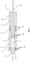
- a cylinder of a locking system is designated by reference number 1.
- the cylinder 1 is designed to be double-walled and accordingly has an inner sleeve 1a, an outer sleeve 1b, a cover 1c, and a base 1d.
- a piston 2 with a piston rod 2a is arranged in the inner sleeve 1a.
- the piston and the piston rod can also have the same diameter, unlike in this exemplary embodiment.
- the piston rod 2a protrudes from the cover-side end of the cylinder 1 and can be moved axially out of the cylinder 1.
- the piston 2 also has annular piston seals 2b running around its outer circumference.
- a hollow cylindrical compensating body 3 is arranged in the annular space between the outer sleeve 1b and the inner sleeve 1a.
- the compensating body 3 has seals 3a on its inner surface and its outer surface.
- An axially displaceable closure part 4 is also arranged at the bottom end of the cylinder 1.
- the closure part 4 instructs seals 4a all around its outer sides.
- the closure part 4 is adjusted via a suitable control, not shown here.
- the control can be designed, for example, as a mechanical lever or spring, but hydraulic or electronic control is also possible.
- the inner sleeve 1a and the outer sleeve 1b have corresponding threads at the end on the cover side.
- the inner sleeve 1a can therefore be screwed onto the outer sleeve 1b.
- the locking system according to the invention thus has two fluid chambers, namely an outer fluid chamber 5, which is delimited by the inner wall of the outer shell 1b and by the outer wall of the inner sleeve 1a as well as the closure part 4 and the compensating body 3, and an inner cylindrical fluid chamber 6, which runs through the interior the inner sleeve 1a as well as the piston 2 and the closure part 4 is defined.
- an outer fluid chamber 5 which is delimited by the inner wall of the outer shell 1b and by the outer wall of the inner sleeve 1a as well as the closure part 4 and the compensating body 3
- an inner cylindrical fluid chamber 6 which runs through the interior the inner sleeve 1a as well as the piston 2 and the closure part 4 is defined.
- the volume of the outer fluid chamber 5 decreases accordingly and the volume of the inner fluid chamber 6 increases to the same extent.
- the sum of the two volumes remains the same.
- the area between compensating body 3 and cover 1c fills with air. This is the case
- the screw connection between the inner sleeve 1a and the outer sleeve 1b is designed to be air-permeable. However, it is also possible to provide specially suitable openings on the cover 1c.
- the closure part 4 can be guided into the closed position by means of the control, so that no more fluid can flow between the two fluid chambers 5, 6.
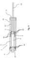
- This system state is in Figure 4 shown.
- the piston rod 2a can therefore no longer be moved.
- the locking system according to the invention is in a static state. The holding force under tensile load extends up to the evaporation pressure of the fluid.
- the closure part 4 can be controlled via an active control command. However, it is also possible to implement the control in a restoring manner, for example via a return spring. In this embodiment, the closure part 4 is held in the closed position in the normal state by the restoring force of the spring. If the restoring force is overcome by pressure on the piston rod, the closure part opens. If the piston 2 is to be moved towards the cover 1c, the closure part 4 must be opened using the active control command described.
- Figure 5 shows a 3D view of the closure part 4.
- the closure part 4 has an annular projection 4b that rises steeply in the radial direction on its outer circumference and a conical, central projection 4c that is rounded at the tip. Due to this shape, the closure part 4 corresponds optimally with the bottom end of the inner sleeve 1a. If the closure part 4 is moved between the opening position and the closing position, a uniform flow gap with very uniform flow properties is formed. By precisely adjusting the closure part 4, a desired damping of the mobility of the piston rod 2a can also be set. Due to the shape, the intensity of the damping is almost linear depending on the gap width or the position of the closure part. The damping can also be influenced by the viscosity of the fluid used.
- the locking system according to the invention is characterized overall by a very simple and inexpensive structure. It is easy to install regardless of the installation position and works with high precision.
Landscapes
- Engineering & Computer Science (AREA)
- General Engineering & Computer Science (AREA)
- Mechanical Engineering (AREA)
- Physics & Mathematics (AREA)
- Fluid Mechanics (AREA)
- Fluid-Damping Devices (AREA)
- Actuator (AREA)
Description
- Die Erfindung betrifft ein stufenlos einstellbares Arretiersystem umfassend eine Zylinder-Kolben-Anordnung mit einem Zylinder, welcher einen Deckel und einen Boden aufweist, einem im Zylinder verschiebbar angeordneten, an seiner Außenfläche in Umfangsrichtung mindestens eine ringförmige Kolbendichtung aufweisenden Kolben, an welchem eine Kolbenstange angeordnet ist, die mindestens teilweise axial am deckelseitigen Ende des Zylinders herausschiebbar ist, einem zwischen einer Öffnungs- und Schließposition stufenlos einstellbaren Verschlussteil und einem im Zylinder angeordnetem Fluid, wobei der Zylinder doppelwandig mit einer Innenhülse und einer Außenhülse ausgebildet ist, der Kolben in der Innenhülse angeordnet ist, in einem Ringraum zwischen Innenhülse und Außenhülse ein rohrförmiger und an seiner Außen- und Innenfläche in Umfangsrichtung jeweils umlaufende Dichtung aufweisender Ausgleichskörper verschiebbar angeordnet ist, das einstellbare Verschlussteil am bodenseitigen Ende des Zylinders angeordnet ist und das bodenseitige Ende der Innenhülse mittels des Verschlussteils verschließbar ist.
- Ein ähnliches Arretiersystem ist beispielsweise aus der
DE 42 39 681 A1 bekannt. Das dort offenbarte Arretiersystem soll zur stufenlosen Dämpfung und Feststellung von Autotüren eingesetzt werden. Das Verschlussteil ist dort mehrteilig ausgebildet und im Kolben angeordnet. Wenn das dortige Arretiersystem festgestellt ist, sind zwei gegenüberliegende Durchflussöffnungen mittels der zweier Verschlussteile und jeweils einem Duckbill-Ventil verschlossen, indem die Verschlussteile durch eine Feder gegen die Durchflussöffnungen gepresst werden. Wird nun eine axiale Druck- oder Zugkraft auf die Kolbenstange ausgeübt, öffnet entsprechend eines der beiden Verschlussteile, wenn die Federkraft überwunden wird. Der Druck im Innenraum des Kolbens erhöht sich entsprechend, bis das Duckbill-Ventil öffnet und der Durchfluss des Fluids durch den Kolbenkörper somit ermöglicht wird. Die Kolbenstange kann somit in die gewünschte Position verschoben werden. Sobald keine Kraft mehr auf die Kolbenstange ausgeübt wird, werden die Durchflussöffnungen automatisch durch die Rückstellkraft der Feder wieder verschlossen. - Ein Arretiersystem der eingangs genannten Art ist beispielsweise aus der
US 3 415 159 A bekannt. DieCN104613124A offenbart einen weiteren bekannten Dämpfer. - Einsatzgebiete solcher Arretiersysteme sind neben Autotüren beispielsweise Maschinenwartungsklappen in Werkhallen, Brandschutztüren und Montagehilfen bei Möbeln.
- Das bekannte Arretiersystem ist im Aufbau relativ komplex und unflexibel. Die Anordnung des mehrteiligen Verschlussmechanismus im Kolben ist aufwendig und nur mit sehr hohem Aufwand zu warten sowie nur mit äußerst hohem Aufwand adaptierbar. Insbesondere die Anordnung der aus einem elastomeren bestehenden Duckbill-Ventile im Kolben ist sehr aufwendig.
- Es ist daher die Aufgabe der Erfindung bekannte, stufenlos einstellbare Arretiersysteme dahingehend weiterzubilden, dass diese sich durch einen robusten und einfachen Aufbau auszeichnen, auf besonders einfache Art zu warten und zu adaptieren sind und gleichzeitig hochzuverlässig und präzise arbeiten sowie eine verbesserte Strömungsmechanik aufweisen.
- Hierzu schlägt die Erfindung ein Arretiersystem gemäß den Merkmalen des Anspruchs 1 vor. Hierdurch ist die Durchflussöffnung durch eine besonders geeignete Strömungsmechanik gekennzeichnet.
- Durch die erfindungsgemäße Ausbildung des Arretiersystems werden eine innere und eine äußere gebildet, welche durch das Verschlussteil trennbar sind und in welchen sich das Fluid befindet. Die äußere Fluidkammer ist ein rohrförmiger Ringraum zwischen Innenhülse und Außenhülse, welcher bodenseitig durch den Verschlusskörper und deckelseitig durch den Ausgleichskörper begrenzt ist. Die innere Fluidkammer entspricht dem zylinderförmigen Raum in der Innenhülse, welcher bodenseitig ebenfalls durch das Verschlussteil und deckelseitig durch den Kolben begrenzt ist.
- Das Verschlussteil kann die Verbindung zwischen diesen beiden Fluidkammern öffnen, begrenzen und schließen. Wenn sich das Verschlussteil in der Öffnungsposition befindet, kann die Kolbenstange axial verschoben werden. Je nach Richtung der Verschiebung strömt das Fluid von der einen in die jeweils andere Fluidkammer. Je schmaler die Öffnung eingestellt wird, desto höher ist die Dämpfung der Beweglichkeit der Kolbenstange. Befindet sich das Verschlussteil in der Schließposition, ist die Kolbenstange festgestellt und lässt sich nicht bewegen.
- Die Einstellung des Verschlussteils kann je nach Anforderung über eine geeignete Steuervorrichtung durchgeführt werden, beispielsweise in Form von einem mechanischen Hebel, einer Feder, über eine hydraulische Ansteuerung oder in Form einer elektronischen Ansteuerung. Eine bevorzugte Ausführungsform sieht vor, dass die Steuervorrichtung außerhalb des Zylinders angeordnet ist. Hierdurch wird ermöglicht, dass die Steuervorrichtung und damit ein Wesentlicher Teil der Wirkungsweise des Arretiersystems jederzeit an geänderte Anforderungen adaptiert werden kann.
- Eine weitere vorteilhafte Weiterbildung der Erfindung sieht vor, dass die Innenhülse und die Außenhülse form- und/oder kraftschlüssig miteinander verbunden sind. Eine solche lösbare Verbindung ermöglicht einen besonders einfachen Zusammenbau sowie eine unproblematische Wartung des Arretiersystems.
- Besonders geeignet zur Herstellung der Verbindung sind miteinander korrespondierende Schraubgewinde an der Innenhülse und der Außenhülse.
- Weiterhin ist es von Vorteil, wenn das Verschlussteil als rotationssymmetrischer Körper bezogen auf die Längsachse des Zylinders ausgebildet ist. Durch die Rotationssymmetrie lässt sich eine besonders gleichmäßige Strömung des Fluids zwischen den beiden Fluidkammern realisieren.
- Als Fluid wird vorzugsweise ein Hydrauliköl eingesetzt.
- Die Erfindung wird im Folgenden anhand der Zeichnungen näher erläutert. Es zeigen:
- Figur 1:
- schematisch einen Querschnitt durch ein erfindungsgemäßes Arretiersystem im dynamischen Zustand in einem Ausführungsbeispiel;
- Figur 2, 3 und 4:
- schematisch die Ein- und Feststellung der Kolbenstange bei dem Ausführungsbeispiel nach
Figur 1 ; - Figur 5:
- schematisch das Verschlussteil des Arretiersystems aus
Figur 1 in 3D-Ansicht. - In
Figur 1 ist ein Zylinder eines erfindungsgemäßen Arretiersystems mit dem Bezugszeichen 1 bezeichnet. Der Zylinder 1 ist doppelwandig ausgestaltet und weist entsprechend eine Innenhülse 1a, eine Außenhülse 1b, einen Deckel 1c, und einen Boden 1d auf. In der Innenhülse 1a ist ein Kolben 2 mit einer Kolbenstange 2a angeordnet. Der Kolben und die Kolbenstange können erfindungsgemäß anders als in diesem Ausführungsbeispiel auch den gleichen Durchmesser aufweisen. Die Kolbenstange 2a ragt aus dem deckelseitigen Ende des Zylinders 1 hinaus und ist axial aus dem Zylinder 1 verschiebbar. Der Kolben 2 weist zudem an seinem Außenumfang umlaufende ringförmige Kolbendichtungen 2b auf. Im Ringraum zwischen Außenhülse 1b und Innenhülse 1a ist ein hohlzylinderförmiger Ausgleichskörper 3 angeordnet. Der Ausgleichskörper 3 weist an seiner Innenfläche und seiner Außenfläche Dichtungen 3a auf. Am bodenseitigen Ende des Zylinders 1 ist des Weiteren ein axial verschiebbares Verschlussteil 4 angeordnet. Das Verschlussteil 4 weist an seinen Außenseiten umlaufende Dichtungen 4a auf. Die Einstellung des Verschlussteils 4 wird über eine hier nicht dargestellte, geeignete Ansteuerung realisiert. Die Ansteuerung kann beispielsweise als mechanischer Hebel oder Feder ausgebildet sein, aber auch eine hydraulische oder elektronische Ansteuerung ist möglich. - Die Innenhülse 1a und die Außenhülse 1b weisen am deckelseitigen Ende korrespondierende Gewinde auf. Die Innenhülse 1a kann also auf die Außenhülse 1b aufgeschraubt werden.
- Das erfindungsgemäße Arretiersystem weist somit zwei Fluidkammern auf, nämlich eine äußere Fluidkammern 5, welche durch die Innenwand der Außenhülle 1b und durch die Außenwand der Innenhülse 1a sowie das Verschlussteil 4 und den Ausgleichskörper 3 begrenzt wird und eine innere zylinderförmige Fluidkammer 6, welche durch den Innenraum der Innenhülse 1a sowie den Kolben 2 und das Verschlussteil 4 definiert wird. Wenn sich das Verschlussteil 4 in der Öffnungsposition befindet, wie in
Figur 1 dargestellt, kann das Fluid von der äußeren Fluidkammer 5 in die innere Fluidkammer 6 strömen und umgekehrt. - Anhand der
Figur 2 ,3 und4 wird im Folgenden die Funktion des erfindungsgemäßen Arretiersystems näher beschrieben. InFigur 2 ist die Kolbenstange 2 weit eingefahren. Die innere Fluidkammer 6 weist daher nur ein sehr kleines Volumen auf. Der Ausgleichskörper 3 befindet sich am deckelseitigen Ende des Zylinders 1, sodass das Volumen der äußeren Fluidkammer 6 maximal ist. Das Verschlussteil 4 ist in der Öffnungsposition. Das heißt, dass das Fluid zischen den Fluidkammern 5, 6 hin und her strömen kann. Wird nun eine Zugkraft F auf die Kolbenstange 2a ausgeübt, wird der Kolben 2 in Richtung des deckelseitigen Endes des Zylinders 1 verschoben, wie inFigur 2 dargestellt. Das Fluid strömt von der äußeren Fluidkammer 5 in die innere Fluidkammer 6. Der Ausgleichkörper 3 wird in Richtung des bodenseitigen Endes des Zylinders 1 verschoben. Das Volumen der äußeren Fluidkammer 5 verkleinert sich entsprechend und das Volumen der inneren Fluidkammer 6 vergrößert sich im gleichen Maße. Die Summe der beiden Volumina bleibt gleich. Der Bereich zwischen Ausgleichskörper 3 und Deckel 1c füllt sich mit Luft. Hierzu ist die Verschraubung zwischen Innenhülse 1a und Außenhülse 1b luftdurchlässig ausgeführt. Es ist aber auch möglich hierzu extra geeignete Öffnungen am Deckel 1c vorzusehen. - Sobald die Kolbenstange 2a in der gewünschten Position ist, kann das Verschlussteil 4 mittels der Ansteuerung in die Schließposition geführt werden, sodass kein Fluid mehr zwischen den beiden Fluidkammern 5, 6 fließen kann. Dieser Systemzustand ist in
Figur 4 dargestellt. Die Kolbenstange 2a kann entsprechend nicht mehr bewegt werden. Das erfindungsgemäße Arretiersystem ist in einem statischen Zustand. Die Haltekraft bei Zugbelastung reicht hier bis zum Verdampfungsdruck des Fluids. - Die Ansteuerung des Verschlussteils 4 kann über einen aktiven Steuerbefehl ausgeführt werden. Es ist aber auch möglich, die Ansteuerung rückstellend beispielsweise über eine Rückstellfeder zu realisieren. Bei dieser Ausführungsform wird das Verschlussteil 4 im Normalzustand durch die Rückstallkraft der Feder in der Schließposition gehalten. Wird die Rückstellkraft durch Druckbelastung der Kolbenstange überwunden, öffnet das Verschlussteil. Soll der Kolben 2 in Richtung Deckel 1c bewegt werden, muss das Verschlussteil 4 über den beschriebenen aktiven Steuerbefehl geöffnet werden.
-
Figur 5 zeigt eine 3D-Ansicht des Verschlussteils 4. Das Verschlussteil 4 weist einen in radialer Richtung steil ansteigenden, ringförmigen Vorsprung 4b an seinem Außenumfang und einen kegelförmigen, an der Spitze abgerundeten, zentralen Vorsprung 4c auf. Durch diese Formgebung korrespondiert das Verschlussteil 4 in optimaler Weise mit dem bodenseitigen Ende der Innenhülse 1a. Wird das Verschlussteil 4 zwischen der Öffnungsposition und Schließposition verschoben bildet sich ein gleichmäßiger Durchflussspalt mit sehr gleichmäßigen Strömungseigenschaften. Durch exakte Einstellung des Verschlussteils 4 kann somit auch eine gewünschte Dämpfung der Beweglichkeit der Kolbenstange 2a eingestellt werden. Durch die Formgebung verläuft die Intensität der Dämpfung nahezu linear abhängig von der Spaltbreite respektive der Position des Verschlussteils. Die Dämpfung lässt sich auch durch die Viskosität des eingesetzten Fluids beeinflussen. - Das erfindungsgemäße Arretiersystem zeichnet sich insgesamt durch einen sehr einfachen und kostengünstigen Aufbau aus. Es ist einfach und unabhängig von der Einbaulage zu montieren und arbeitet hochpräzise.
-
- 1
- Zylinder
- 1a
- Innenhülse
- 1b
- Außenhülse
- 1c
- Deckel
- 1d
- Boden
- 2
- Kolben
- 2a
- Kolbenstange
- 2b
- Kolbendichtung
- 3
- Ausgleichskörper
- 3a
- Dichtung
- 4
- Verschlussteil
- 4a
- Dichtung
- 4b
- ringförmiger Vorsprung
- 4c
- kegelförmiger Vorsprung
- 5
- äußere Fluidkammer
- 6
- innere Fluidkammer
- 5
- äußere Fluidkammer
- 6
- innere Fluidkammer
Claims (6)
- Stufenlos einstellbares Arretiersystem umfassend eine Zylinder-Kolben-Anordnung mit einem Zylinder (1), welcher einen Deckel (1c) und einen Boden (1d) aufweist, einem im Zylinder (1) verschiebbar angeordneten, an seiner Außenfläche in Umfangsrichtung mindestens eine ringförmige Kolbendichtung (2a) aufweisenden Kolben (2), an welchem eine Kolbenstange (2b) angeordnet ist, die mindestens teilweise axial am deckelseitigen Ende des Zylinders (1) herausschiebbar ist, einem zwischen einer Öffnungs- und Schließposition stufenlos einstellbaren Verschlussteil (4) und einem im Zylinder (1) angeordneten Fluid, wobei der Zylinder doppelwandig mit einer Innenhülse (1a) und einer Außenhülse (1b) ausgebildet ist, der Kolben (2) in der Innenhülse (1a) angeordnet ist, in einem Ringraum zwischen Innenhülse (1a) und Außenhülse (1b) ein rohrförmiger und an seiner Außen- und Innenfläche in Umfangsrichtung jeweils umlaufende Dichtungen (3a) aufweisender Ausgleichkörper (3) verschiebbar angeordnet ist, das Verschlussteil (4) am bodenseitigen Ende (3) des Zylinders (1) angeordnet ist und das bodenseitige Ende der Innenhülse (1a) mittels des Verschlussteils (4) verschließbar ist,
dadurch gekennzeichnet,
dass das Verschlussteil (4) axial verschiebbar ist und einen in axialer Richtung anwachsenden ringförmigen Vorsprung (4b) am Außenumfang und einen kegelförmigen zentralen Vorsprung (4c) aufweist, wobei der ringförmige Vorsprung (4b) und der zentrale Vorsprung (4c) in Richtung der Innenhülse (1a) weisen, sodass sich zwischen Verschlussteil (4) und Innenhülse (1a) ein verschließbarer Durchflussspalt bildet, dessen Breite abhängig von der Position des Verschlussteils (4) ist. - Arretiersystem nach Anspruch 1, gekennzeichnet durch, eine außerhalb des Zylinders angeordnete Steuervorrichtung, welche auf das Verschlussteil (4) wirkt.
- Arretiersystem nach Anspruch 1 oder 2, dadurch gekennzeichnet, dass die Innenhülse (1a) und die Außenhülse (1b) lösbar, form- und/oder kraftschlüssig miteinander verbunden sind.
- Arretiersystem nach Anspruch 3, dadurch gekennzeichnet, dass die Innenhülse (1a) und die Außenhülse (1b) mittels korrespondierender Schraubgewinde miteinander verbindbar sind.
- Arretiersystem nach einem der vorgenannten Ansprüche, dadurch gekennzeichnet, dass das Verschlussteil (3) als rotationssymmetrischer Körper bezogen auf die Längsachse des Zylinders (1) ausgebildet ist
- Arretiersystem nach Anspruch 1, dadurch gekennzeichnet, dass das Fluid ein Hydrauliköl ist.
Applications Claiming Priority (3)
| Application Number | Priority Date | Filing Date | Title |
|---|---|---|---|
| DE102020003133 | 2020-05-26 | ||
| DE102021100029.7A DE102021100029A1 (de) | 2020-05-26 | 2021-01-04 | Arretiersystem |
| PCT/EP2021/063909 WO2021239733A1 (de) | 2020-05-26 | 2021-05-25 | Arretiersystem |
Publications (3)
| Publication Number | Publication Date |
|---|---|
| EP4062082A1 EP4062082A1 (de) | 2022-09-28 |
| EP4062082B1 true EP4062082B1 (de) | 2024-01-10 |
| EP4062082C0 EP4062082C0 (de) | 2024-01-10 |
Family
ID=78509178
Family Applications (1)
| Application Number | Title | Priority Date | Filing Date |
|---|---|---|---|
| EP21732811.1A Active EP4062082B1 (de) | 2020-05-26 | 2021-05-25 | Arretiersystem |
Country Status (7)
| Country | Link |
|---|---|
| US (1) | US12129908B2 (de) |
| EP (1) | EP4062082B1 (de) |
| JP (1) | JP7731376B2 (de) |
| CN (1) | CN116249845B (de) |
| DE (1) | DE102021100029A1 (de) |
| MX (1) | MX2022014863A (de) |
| WO (1) | WO2021239733A1 (de) |
Families Citing this family (2)
| Publication number | Priority date | Publication date | Assignee | Title |
|---|---|---|---|---|
| CN116733815A (zh) * | 2023-07-13 | 2023-09-12 | 珠海三锐精工科技有限公司 | 一种拉杆连接结构 |
| CN117662662B (zh) * | 2023-11-30 | 2024-08-02 | 比亚迪股份有限公司 | 减振总成和具有其的悬架系统、车辆 |
Citations (1)
| Publication number | Priority date | Publication date | Assignee | Title |
|---|---|---|---|---|
| CN104613124A (zh) * | 2015-02-04 | 2015-05-13 | 吉林大学 | 一种双活塞电流变减振器 |
Family Cites Families (17)
| Publication number | Priority date | Publication date | Assignee | Title |
|---|---|---|---|---|
| JPS416091Y1 (de) * | 1964-10-09 | 1966-03-30 | ||
| DE1301026B (de) * | 1964-11-14 | 1969-08-14 | Reinhard Hoernlein Kg Holz Und | Hydropneumatisches Hebeaggregat, insbesondere fuer hoehenverstellbare Tische und Stuehle |
| JPS6121438A (ja) * | 1984-07-10 | 1986-01-30 | Taiho Kogyo Co Ltd | ショックアブソ−バ |
| US4824081A (en) * | 1985-03-22 | 1989-04-25 | Grazina J. Pauliukonis | Pistonless-plunger positioner with internal cylinder and annular fluid space |
| US5285877A (en) * | 1990-09-22 | 1994-02-15 | Boge Aktiengesellschaft | Impact damper |
| US5115723A (en) * | 1991-04-30 | 1992-05-26 | John Wang | Height adjusting device |
| DE4239681A1 (de) | 1992-11-26 | 1994-06-01 | Brose Fahrzeugteile | Stufenlos wirkender Türfeststeller, insbesondere für eine Fahrzeugtür |
| JP3700951B2 (ja) * | 1996-01-22 | 2005-09-28 | カヤバ工業株式会社 | フロントフォーク |
| JP2009299769A (ja) * | 2008-06-12 | 2009-12-24 | Kayaba Ind Co Ltd | 液圧緩衝器 |
| DE102009003248B4 (de) * | 2009-05-19 | 2011-12-29 | Saf-Holland Gmbh | Stabilisierungsvorrichtung für Achsen von Fahrzeugen |
| DE102011055688B4 (de) * | 2011-11-24 | 2023-02-09 | Stabilus Gmbh | Arretierbares Kolben-Zylinder-Aggregat |
| CN104315064A (zh) * | 2014-09-10 | 2015-01-28 | 张家港市宏盛贸易有限公司 | 纺织机减震器 |
| DE102016210162A1 (de) * | 2016-06-08 | 2017-12-14 | Suspa Gmbh | Führungs-/Dämpfungseinheit und Kolbengehäuseeinheit |
| CN207005175U (zh) | 2017-06-08 | 2018-02-13 | 常州市莱特气弹簧有限公司 | 压力可调气弹簧 |
| US10549803B2 (en) * | 2017-06-30 | 2020-02-04 | Sram, Llc | Seat post assembly |
| US10668968B2 (en) * | 2017-06-30 | 2020-06-02 | Sram, Llc | Seat post assembly |
| US11959327B2 (en) * | 2017-08-09 | 2024-04-16 | Wolfgang Held | Fluid damper for parts that are movable relative to one another, comprising a piston guided movably in a cylinder |
-
2021
- 2021-01-04 DE DE102021100029.7A patent/DE102021100029A1/de active Pending
- 2021-05-25 WO PCT/EP2021/063909 patent/WO2021239733A1/de not_active Ceased
- 2021-05-25 EP EP21732811.1A patent/EP4062082B1/de active Active
- 2021-05-25 MX MX2022014863A patent/MX2022014863A/es unknown
- 2021-05-25 JP JP2022572572A patent/JP7731376B2/ja active Active
- 2021-05-25 CN CN202180060738.5A patent/CN116249845B/zh active Active
- 2021-05-25 US US17/927,907 patent/US12129908B2/en active Active
Patent Citations (1)
| Publication number | Priority date | Publication date | Assignee | Title |
|---|---|---|---|---|
| CN104613124A (zh) * | 2015-02-04 | 2015-05-13 | 吉林大学 | 一种双活塞电流变减振器 |
Also Published As
| Publication number | Publication date |
|---|---|
| WO2021239733A1 (de) | 2021-12-02 |
| JP2023528346A (ja) | 2023-07-04 |
| DE102021100029A1 (de) | 2021-12-02 |
| CN116249845A (zh) | 2023-06-09 |
| EP4062082A1 (de) | 2022-09-28 |
| EP4062082C0 (de) | 2024-01-10 |
| CN116249845B (zh) | 2024-08-20 |
| MX2022014863A (es) | 2023-03-06 |
| JP7731376B2 (ja) | 2025-08-29 |
| US20230349400A1 (en) | 2023-11-02 |
| US12129908B2 (en) | 2024-10-29 |
Similar Documents
| Publication | Publication Date | Title |
|---|---|---|
| DE69615121T2 (de) | Gasfeder | |
| DE2619176C2 (de) | Gasfeder mit aufgehobener Ausschubkraft bei eingefahrener Kolbenstange | |
| EP1790873B1 (de) | Verstellelement | |
| AT524746B1 (de) | Hydraulischer Rotationsdämpfer | |
| DE2849267C2 (de) | Gasfeder | |
| DE2624475C3 (de) | Hydraulischer Stoßdämpfer | |
| DE19954326B4 (de) | Fahrzeugbremsanlage mit einem Gasdruckspeicher | |
| DE69025344T2 (de) | Zylinder-Kolben-Vorrichtung | |
| EP1744062B1 (de) | Arbeitszylinder mit Endlagendämpfung | |
| EP3458739B1 (de) | Schwingungsdämpfer mit hubabhängiger dämpfkraft | |
| EP0258812A1 (de) | Stufenlos blockierbare Verstelleinrichtung | |
| DE102011017795B4 (de) | Türschließer | |
| DE69007406T2 (de) | Kolben für Druckzylinder. | |
| EP4062082A1 (de) | Arretiersystem | |
| DE3427843A1 (de) | Hydro-pneumatische aufhaengvorrichtung | |
| DE202007009299U1 (de) | Gasfederanordnung | |
| DE102006034249B3 (de) | Gasfederanordnung | |
| DE10158123A1 (de) | Endlagengedämpfter Druckmittelzylinder | |
| DE19721137B4 (de) | Blockierbare Gasfeder mit schneller Ausschubgeschwindigkeit | |
| DE102005030403B4 (de) | Verstellelement | |
| WO2021115527A1 (de) | Vorrichtung zur regelung von drücken eines strömungsmittels mit einem ventil | |
| DE102007018582B4 (de) | Kolben-Zylinderaggregat | |
| DE102016101664A1 (de) | Axialventil | |
| DE1530207C3 (de) | Hydraulisch gedämpfte Stoßaufnahmevorrichtung für Eisenbahnwagen | |
| DE10319054A1 (de) | Gasfeder |
Legal Events
| Date | Code | Title | Description |
|---|---|---|---|
| STAA | Information on the status of an ep patent application or granted ep patent |
Free format text: STATUS: UNKNOWN |
|
| STAA | Information on the status of an ep patent application or granted ep patent |
Free format text: STATUS: THE INTERNATIONAL PUBLICATION HAS BEEN MADE |
|
| PUAI | Public reference made under article 153(3) epc to a published international application that has entered the european phase |
Free format text: ORIGINAL CODE: 0009012 |
|
| STAA | Information on the status of an ep patent application or granted ep patent |
Free format text: STATUS: REQUEST FOR EXAMINATION WAS MADE |
|
| 17P | Request for examination filed |
Effective date: 20220620 |
|
| AK | Designated contracting states |
Kind code of ref document: A1 Designated state(s): AL AT BE BG CH CY CZ DE DK EE ES FI FR GB GR HR HU IE IS IT LI LT LU LV MC MK MT NL NO PL PT RO RS SE SI SK SM TR |
|
| STAA | Information on the status of an ep patent application or granted ep patent |
Free format text: STATUS: EXAMINATION IS IN PROGRESS |
|
| 17Q | First examination report despatched |
Effective date: 20221031 |
|
| RAP1 | Party data changed (applicant data changed or rights of an application transferred) |
Owner name: DETEC RELIABLE SOLUTIONS GMBH |
|
| GRAP | Despatch of communication of intention to grant a patent |
Free format text: ORIGINAL CODE: EPIDOSNIGR1 |
|
| STAA | Information on the status of an ep patent application or granted ep patent |
Free format text: STATUS: GRANT OF PATENT IS INTENDED |
|
| DAV | Request for validation of the european patent (deleted) | ||
| DAX | Request for extension of the european patent (deleted) | ||
| INTG | Intention to grant announced |
Effective date: 20230731 |
|
| GRAS | Grant fee paid |
Free format text: ORIGINAL CODE: EPIDOSNIGR3 |
|
| GRAA | (expected) grant |
Free format text: ORIGINAL CODE: 0009210 |
|
| STAA | Information on the status of an ep patent application or granted ep patent |
Free format text: STATUS: THE PATENT HAS BEEN GRANTED |
|
| AK | Designated contracting states |
Kind code of ref document: B1 Designated state(s): AL AT BE BG CH CY CZ DE DK EE ES FI FR GB GR HR HU IE IS IT LI LT LU LV MC MK MT NL NO PL PT RO RS SE SI SK SM TR |
|
| REG | Reference to a national code |
Ref country code: GB Ref legal event code: FG4D Free format text: NOT ENGLISH |
|
| RIN1 | Information on inventor provided before grant (corrected) |
Inventor name: SEUTHE, ADRIAN Inventor name: ROTTLAENDER, HENDRIK |
|
| REG | Reference to a national code |
Ref country code: CH Ref legal event code: EP |
|
| REG | Reference to a national code |
Ref country code: DE Ref legal event code: R096 Ref document number: 502021002453 Country of ref document: DE |
|
| REG | Reference to a national code |
Ref country code: IE Ref legal event code: FG4D Free format text: LANGUAGE OF EP DOCUMENT: GERMAN |
|
| U01 | Request for unitary effect filed |
Effective date: 20240125 |
|
| U07 | Unitary effect registered |
Designated state(s): AT BE BG DE DK EE FI FR IT LT LU LV MT NL PT SE SI Effective date: 20240201 |
|
| PG25 | Lapsed in a contracting state [announced via postgrant information from national office to epo] |
Ref country code: IS Free format text: LAPSE BECAUSE OF FAILURE TO SUBMIT A TRANSLATION OF THE DESCRIPTION OR TO PAY THE FEE WITHIN THE PRESCRIBED TIME-LIMIT Effective date: 20240510 |
|
| U20 | Renewal fee for the european patent with unitary effect paid |
Year of fee payment: 4 Effective date: 20240527 |
|
| PG25 | Lapsed in a contracting state [announced via postgrant information from national office to epo] |
Ref country code: GR Free format text: LAPSE BECAUSE OF FAILURE TO SUBMIT A TRANSLATION OF THE DESCRIPTION OR TO PAY THE FEE WITHIN THE PRESCRIBED TIME-LIMIT Effective date: 20240411 |
|
| PG25 | Lapsed in a contracting state [announced via postgrant information from national office to epo] |
Ref country code: HR Free format text: LAPSE BECAUSE OF FAILURE TO SUBMIT A TRANSLATION OF THE DESCRIPTION OR TO PAY THE FEE WITHIN THE PRESCRIBED TIME-LIMIT Effective date: 20240110 Ref country code: RS Free format text: LAPSE BECAUSE OF FAILURE TO SUBMIT A TRANSLATION OF THE DESCRIPTION OR TO PAY THE FEE WITHIN THE PRESCRIBED TIME-LIMIT Effective date: 20240410 |
|
| PG25 | Lapsed in a contracting state [announced via postgrant information from national office to epo] |
Ref country code: ES Free format text: LAPSE BECAUSE OF FAILURE TO SUBMIT A TRANSLATION OF THE DESCRIPTION OR TO PAY THE FEE WITHIN THE PRESCRIBED TIME-LIMIT Effective date: 20240110 |
|
| PG25 | Lapsed in a contracting state [announced via postgrant information from national office to epo] |
Ref country code: RS Free format text: LAPSE BECAUSE OF FAILURE TO SUBMIT A TRANSLATION OF THE DESCRIPTION OR TO PAY THE FEE WITHIN THE PRESCRIBED TIME-LIMIT Effective date: 20240410 Ref country code: NO Free format text: LAPSE BECAUSE OF FAILURE TO SUBMIT A TRANSLATION OF THE DESCRIPTION OR TO PAY THE FEE WITHIN THE PRESCRIBED TIME-LIMIT Effective date: 20240410 Ref country code: IS Free format text: LAPSE BECAUSE OF FAILURE TO SUBMIT A TRANSLATION OF THE DESCRIPTION OR TO PAY THE FEE WITHIN THE PRESCRIBED TIME-LIMIT Effective date: 20240510 Ref country code: HR Free format text: LAPSE BECAUSE OF FAILURE TO SUBMIT A TRANSLATION OF THE DESCRIPTION OR TO PAY THE FEE WITHIN THE PRESCRIBED TIME-LIMIT Effective date: 20240110 Ref country code: GR Free format text: LAPSE BECAUSE OF FAILURE TO SUBMIT A TRANSLATION OF THE DESCRIPTION OR TO PAY THE FEE WITHIN THE PRESCRIBED TIME-LIMIT Effective date: 20240411 Ref country code: ES Free format text: LAPSE BECAUSE OF FAILURE TO SUBMIT A TRANSLATION OF THE DESCRIPTION OR TO PAY THE FEE WITHIN THE PRESCRIBED TIME-LIMIT Effective date: 20240110 |
|
| PG25 | Lapsed in a contracting state [announced via postgrant information from national office to epo] |
Ref country code: PL Free format text: LAPSE BECAUSE OF FAILURE TO SUBMIT A TRANSLATION OF THE DESCRIPTION OR TO PAY THE FEE WITHIN THE PRESCRIBED TIME-LIMIT Effective date: 20240110 |
|
| PG25 | Lapsed in a contracting state [announced via postgrant information from national office to epo] |
Ref country code: PL Free format text: LAPSE BECAUSE OF FAILURE TO SUBMIT A TRANSLATION OF THE DESCRIPTION OR TO PAY THE FEE WITHIN THE PRESCRIBED TIME-LIMIT Effective date: 20240110 |
|
| REG | Reference to a national code |
Ref country code: DE Ref legal event code: R097 Ref document number: 502021002453 Country of ref document: DE |
|
| PG25 | Lapsed in a contracting state [announced via postgrant information from national office to epo] |
Ref country code: SM Free format text: LAPSE BECAUSE OF FAILURE TO SUBMIT A TRANSLATION OF THE DESCRIPTION OR TO PAY THE FEE WITHIN THE PRESCRIBED TIME-LIMIT Effective date: 20240110 |
|
| PG25 | Lapsed in a contracting state [announced via postgrant information from national office to epo] |
Ref country code: CZ Free format text: LAPSE BECAUSE OF FAILURE TO SUBMIT A TRANSLATION OF THE DESCRIPTION OR TO PAY THE FEE WITHIN THE PRESCRIBED TIME-LIMIT Effective date: 20240110 |
|
| PG25 | Lapsed in a contracting state [announced via postgrant information from national office to epo] |
Ref country code: SK Free format text: LAPSE BECAUSE OF FAILURE TO SUBMIT A TRANSLATION OF THE DESCRIPTION OR TO PAY THE FEE WITHIN THE PRESCRIBED TIME-LIMIT Effective date: 20240110 |
|
| PG25 | Lapsed in a contracting state [announced via postgrant information from national office to epo] |
Ref country code: SM Free format text: LAPSE BECAUSE OF FAILURE TO SUBMIT A TRANSLATION OF THE DESCRIPTION OR TO PAY THE FEE WITHIN THE PRESCRIBED TIME-LIMIT Effective date: 20240110 Ref country code: SK Free format text: LAPSE BECAUSE OF FAILURE TO SUBMIT A TRANSLATION OF THE DESCRIPTION OR TO PAY THE FEE WITHIN THE PRESCRIBED TIME-LIMIT Effective date: 20240110 Ref country code: RO Free format text: LAPSE BECAUSE OF FAILURE TO SUBMIT A TRANSLATION OF THE DESCRIPTION OR TO PAY THE FEE WITHIN THE PRESCRIBED TIME-LIMIT Effective date: 20240110 Ref country code: CZ Free format text: LAPSE BECAUSE OF FAILURE TO SUBMIT A TRANSLATION OF THE DESCRIPTION OR TO PAY THE FEE WITHIN THE PRESCRIBED TIME-LIMIT Effective date: 20240110 |
|
| PLBE | No opposition filed within time limit |
Free format text: ORIGINAL CODE: 0009261 |
|
| STAA | Information on the status of an ep patent application or granted ep patent |
Free format text: STATUS: NO OPPOSITION FILED WITHIN TIME LIMIT |
|
| 26N | No opposition filed |
Effective date: 20241011 |
|
| REG | Reference to a national code |
Ref country code: CH Ref legal event code: PL |
|
| PG25 | Lapsed in a contracting state [announced via postgrant information from national office to epo] |
Ref country code: MC Free format text: LAPSE BECAUSE OF FAILURE TO SUBMIT A TRANSLATION OF THE DESCRIPTION OR TO PAY THE FEE WITHIN THE PRESCRIBED TIME-LIMIT Effective date: 20240110 |
|
| PG25 | Lapsed in a contracting state [announced via postgrant information from national office to epo] |
Ref country code: MC Free format text: LAPSE BECAUSE OF FAILURE TO SUBMIT A TRANSLATION OF THE DESCRIPTION OR TO PAY THE FEE WITHIN THE PRESCRIBED TIME-LIMIT Effective date: 20240110 Ref country code: CH Free format text: LAPSE BECAUSE OF NON-PAYMENT OF DUE FEES Effective date: 20240531 |
|
| PG25 | Lapsed in a contracting state [announced via postgrant information from national office to epo] |
Ref country code: IE Free format text: LAPSE BECAUSE OF NON-PAYMENT OF DUE FEES Effective date: 20240525 |
|
| U20 | Renewal fee for the european patent with unitary effect paid |
Year of fee payment: 5 Effective date: 20250528 |
|
| PGFP | Annual fee paid to national office [announced via postgrant information from national office to epo] |
Ref country code: GB Payment date: 20250530 Year of fee payment: 5 |
|
| PG25 | Lapsed in a contracting state [announced via postgrant information from national office to epo] |
Ref country code: HU Free format text: LAPSE BECAUSE OF FAILURE TO SUBMIT A TRANSLATION OF THE DESCRIPTION OR TO PAY THE FEE WITHIN THE PRESCRIBED TIME-LIMIT; INVALID AB INITIO Effective date: 20210525 |
|
| PG25 | Lapsed in a contracting state [announced via postgrant information from national office to epo] |
Ref country code: CY Free format text: LAPSE BECAUSE OF FAILURE TO SUBMIT A TRANSLATION OF THE DESCRIPTION OR TO PAY THE FEE WITHIN THE PRESCRIBED TIME-LIMIT; INVALID AB INITIO Effective date: 20210525 |