EP4062098B1 - Kombiniertes leuchtmodul zur abbildung der beleuchteten fläche eines kollektors - Google Patents
Kombiniertes leuchtmodul zur abbildung der beleuchteten fläche eines kollektors Download PDFInfo
- Publication number
- EP4062098B1 EP4062098B1 EP20808114.1A EP20808114A EP4062098B1 EP 4062098 B1 EP4062098 B1 EP 4062098B1 EP 20808114 A EP20808114 A EP 20808114A EP 4062098 B1 EP4062098 B1 EP 4062098B1
- Authority
- EP
- European Patent Office
- Prior art keywords
- reflective surface
- light
- light source
- luminous module
- optical axis
- Prior art date
- Legal status (The legal status is an assumption and is not a legal conclusion. Google has not performed a legal analysis and makes no representation as to the accuracy of the status listed.)
- Active
Links
Images


Classifications
-
- F—MECHANICAL ENGINEERING; LIGHTING; HEATING; WEAPONS; BLASTING
- F21—LIGHTING
- F21S—NON-PORTABLE LIGHTING DEVICES; SYSTEMS THEREOF; VEHICLE LIGHTING DEVICES SPECIALLY ADAPTED FOR VEHICLE EXTERIORS
- F21S41/00—Illuminating devices specially adapted for vehicle exteriors, e.g. headlamps
- F21S41/30—Illuminating devices specially adapted for vehicle exteriors, e.g. headlamps characterised by reflectors
- F21S41/32—Optical layout thereof
- F21S41/33—Multi-surface reflectors, e.g. reflectors with facets or reflectors with portions of different curvature
-
- F—MECHANICAL ENGINEERING; LIGHTING; HEATING; WEAPONS; BLASTING
- F21—LIGHTING
- F21S—NON-PORTABLE LIGHTING DEVICES; SYSTEMS THEREOF; VEHICLE LIGHTING DEVICES SPECIALLY ADAPTED FOR VEHICLE EXTERIORS
- F21S41/00—Illuminating devices specially adapted for vehicle exteriors, e.g. headlamps
- F21S41/10—Illuminating devices specially adapted for vehicle exteriors, e.g. headlamps characterised by the light source
- F21S41/14—Illuminating devices specially adapted for vehicle exteriors, e.g. headlamps characterised by the light source characterised by the type of light source
- F21S41/141—Light emitting diodes [LED]
- F21S41/147—Light emitting diodes [LED] the main emission direction of the LED being angled to the optical axis of the illuminating device
- F21S41/148—Light emitting diodes [LED] the main emission direction of the LED being angled to the optical axis of the illuminating device the main emission direction of the LED being perpendicular to the optical axis
-
- F—MECHANICAL ENGINEERING; LIGHTING; HEATING; WEAPONS; BLASTING
- F21—LIGHTING
- F21S—NON-PORTABLE LIGHTING DEVICES; SYSTEMS THEREOF; VEHICLE LIGHTING DEVICES SPECIALLY ADAPTED FOR VEHICLE EXTERIORS
- F21S41/00—Illuminating devices specially adapted for vehicle exteriors, e.g. headlamps
- F21S41/10—Illuminating devices specially adapted for vehicle exteriors, e.g. headlamps characterised by the light source
- F21S41/14—Illuminating devices specially adapted for vehicle exteriors, e.g. headlamps characterised by the light source characterised by the type of light source
- F21S41/141—Light emitting diodes [LED]
- F21S41/151—Light emitting diodes [LED] arranged in one or more lines
-
- F—MECHANICAL ENGINEERING; LIGHTING; HEATING; WEAPONS; BLASTING
- F21—LIGHTING
- F21S—NON-PORTABLE LIGHTING DEVICES; SYSTEMS THEREOF; VEHICLE LIGHTING DEVICES SPECIALLY ADAPTED FOR VEHICLE EXTERIORS
- F21S41/00—Illuminating devices specially adapted for vehicle exteriors, e.g. headlamps
- F21S41/20—Illuminating devices specially adapted for vehicle exteriors, e.g. headlamps characterised by refractors, transparent cover plates, light guides or filters
- F21S41/25—Projection lenses
-
- F—MECHANICAL ENGINEERING; LIGHTING; HEATING; WEAPONS; BLASTING
- F21—LIGHTING
- F21S—NON-PORTABLE LIGHTING DEVICES; SYSTEMS THEREOF; VEHICLE LIGHTING DEVICES SPECIALLY ADAPTED FOR VEHICLE EXTERIORS
- F21S41/00—Illuminating devices specially adapted for vehicle exteriors, e.g. headlamps
- F21S41/30—Illuminating devices specially adapted for vehicle exteriors, e.g. headlamps characterised by reflectors
- F21S41/32—Optical layout thereof
- F21S41/33—Multi-surface reflectors, e.g. reflectors with facets or reflectors with portions of different curvature
- F21S41/331—Multi-surface reflectors, e.g. reflectors with facets or reflectors with portions of different curvature the reflector consisting of complete annular areas
- F21S41/333—Multi-surface reflectors, e.g. reflectors with facets or reflectors with portions of different curvature the reflector consisting of complete annular areas with discontinuity at the junction between adjacent areas
-
- F—MECHANICAL ENGINEERING; LIGHTING; HEATING; WEAPONS; BLASTING
- F21—LIGHTING
- F21S—NON-PORTABLE LIGHTING DEVICES; SYSTEMS THEREOF; VEHICLE LIGHTING DEVICES SPECIALLY ADAPTED FOR VEHICLE EXTERIORS
- F21S41/00—Illuminating devices specially adapted for vehicle exteriors, e.g. headlamps
- F21S41/30—Illuminating devices specially adapted for vehicle exteriors, e.g. headlamps characterised by reflectors
- F21S41/32—Optical layout thereof
- F21S41/33—Multi-surface reflectors, e.g. reflectors with facets or reflectors with portions of different curvature
- F21S41/334—Multi-surface reflectors, e.g. reflectors with facets or reflectors with portions of different curvature the reflector consisting of patch like sectors
- F21S41/336—Multi-surface reflectors, e.g. reflectors with facets or reflectors with portions of different curvature the reflector consisting of patch like sectors with discontinuity at the junction between adjacent areas
-
- F—MECHANICAL ENGINEERING; LIGHTING; HEATING; WEAPONS; BLASTING
- F21—LIGHTING
- F21S—NON-PORTABLE LIGHTING DEVICES; SYSTEMS THEREOF; VEHICLE LIGHTING DEVICES SPECIALLY ADAPTED FOR VEHICLE EXTERIORS
- F21S41/00—Illuminating devices specially adapted for vehicle exteriors, e.g. headlamps
- F21S41/30—Illuminating devices specially adapted for vehicle exteriors, e.g. headlamps characterised by reflectors
- F21S41/32—Optical layout thereof
- F21S41/33—Multi-surface reflectors, e.g. reflectors with facets or reflectors with portions of different curvature
- F21S41/338—Multi-surface reflectors, e.g. reflectors with facets or reflectors with portions of different curvature the reflector having surface portions added to its general concavity
-
- F—MECHANICAL ENGINEERING; LIGHTING; HEATING; WEAPONS; BLASTING
- F21—LIGHTING
- F21S—NON-PORTABLE LIGHTING DEVICES; SYSTEMS THEREOF; VEHICLE LIGHTING DEVICES SPECIALLY ADAPTED FOR VEHICLE EXTERIORS
- F21S41/00—Illuminating devices specially adapted for vehicle exteriors, e.g. headlamps
- F21S41/40—Illuminating devices specially adapted for vehicle exteriors, e.g. headlamps characterised by screens, non-reflecting members, light-shielding members or fixed shades
- F21S41/43—Illuminating devices specially adapted for vehicle exteriors, e.g. headlamps characterised by screens, non-reflecting members, light-shielding members or fixed shades characterised by the shape thereof
-
- F—MECHANICAL ENGINEERING; LIGHTING; HEATING; WEAPONS; BLASTING
- F21—LIGHTING
- F21V—FUNCTIONAL FEATURES OR DETAILS OF LIGHTING DEVICES OR SYSTEMS THEREOF; STRUCTURAL COMBINATIONS OF LIGHTING DEVICES WITH OTHER ARTICLES, NOT OTHERWISE PROVIDED FOR
- F21V7/00—Reflectors for light sources
- F21V7/04—Optical design
- F21V7/06—Optical design with parabolic curvature
-
- F—MECHANICAL ENGINEERING; LIGHTING; HEATING; WEAPONS; BLASTING
- F21—LIGHTING
- F21V—FUNCTIONAL FEATURES OR DETAILS OF LIGHTING DEVICES OR SYSTEMS THEREOF; STRUCTURAL COMBINATIONS OF LIGHTING DEVICES WITH OTHER ARTICLES, NOT OTHERWISE PROVIDED FOR
- F21V7/00—Reflectors for light sources
- F21V7/04—Optical design
- F21V7/08—Optical design with elliptical curvature
-
- F—MECHANICAL ENGINEERING; LIGHTING; HEATING; WEAPONS; BLASTING
- F21—LIGHTING
- F21W—INDEXING SCHEME ASSOCIATED WITH SUBCLASSES F21K, F21L, F21S and F21V, RELATING TO USES OR APPLICATIONS OF LIGHTING DEVICES OR SYSTEMS
- F21W2102/00—Exterior vehicle lighting devices for illuminating purposes
- F21W2102/10—Arrangement or contour of the emitted light
- F21W2102/13—Arrangement or contour of the emitted light for high-beam region or low-beam region
- F21W2102/135—Arrangement or contour of the emitted light for high-beam region or low-beam region the light having cut-off lines, i.e. clear borderlines between emitted regions and dark regions
- F21W2102/155—Arrangement or contour of the emitted light for high-beam region or low-beam region the light having cut-off lines, i.e. clear borderlines between emitted regions and dark regions having inclined and horizontal cutoff lines
-
- F—MECHANICAL ENGINEERING; LIGHTING; HEATING; WEAPONS; BLASTING
- F21—LIGHTING
- F21W—INDEXING SCHEME ASSOCIATED WITH SUBCLASSES F21K, F21L, F21S and F21V, RELATING TO USES OR APPLICATIONS OF LIGHTING DEVICES OR SYSTEMS
- F21W2107/00—Use or application of lighting devices on or in particular types of vehicles
- F21W2107/10—Use or application of lighting devices on or in particular types of vehicles for land vehicles
Definitions
- the invention relates to the field of lighting and light signaling, more particularly in the automotive field.
- Such a light module conventionally comprises a first collector with a first reflective surface of revolution with an elliptical profile, in the form of a cap in a half-space delimited by a horizontal plane.
- a first essentially point light source, of the light-emitting diode type is located at a first focus of the first reflective surface and illuminates in the half-space in the direction of said surface. The rays are thus reflected in a convergent manner towards a second focus of the first reflective surface.
- An auxiliary reflective surface generally planar, with a cut-off edge at the second focus ensures upward reflection of the rays which do not pass precisely through the second focus, these rays then being refracted by a thick lens towards the bottom of the lighting beam.
- This auxiliary reflective surface is commonly referred to as a "folder” in that it "folds" towards the top of the projection lens the rays which would otherwise form an upper part of the lighting beam.
- This first light beam has a horizontal cut-off, possibly with a kink (commonly referred to as a "kink”) and corresponds to a low-beam type lighting beam (commonly referred to as a "low-beam").
- the second light source may have several separately activatable illuminating zones, and the second reflective surface can be segmented into several sectors, so as to form a segmented light beam.
- Such a light module has the disadvantage of requiring high precision in the positioning of the folder and the cutting edge.
- the projection lens must be a thick lens due to its short focal length, which increases its weight and complicates its production, such as shrinkage defects.
- the collector has a certain height and, therefore, a certain height requirement.
- the document EP 3 369 987 A1 describes another light module comprising a first light source associated with a first reflector and a second light source associated with a second reflector.
- the invention aims to overcome at least one of the drawbacks of the aforementioned state of the art. More particularly, the invention aims to propose a light module capable of forming a potentially cut-off light beam, which is compact and more economical to produce.
- the subject of the invention is a module as defined by claim 1.
- the optical system has a focus located on or near the second reflecting surface and has a sufficient depth of field. This is advantageously at least 30%, more advantageously the entire length, along the optical axis, of the second reflecting surface.
- a large focal length and a reduced height of a projection lens make it possible to obtain a large depth of field.
- the rays incident on the optical system are parallel to the optical axis or are inclined by less than 25°, preferably by less than 15° relative to said optical axis, so as to be in Gaussian conditions.
- the first light beam is advantageously a low-beam automotive lighting beam or a part of such a beam. It may be, for example, a beam with a horizontal flat cutoff or with a step. Alternatively, the first light beam allows
- the second light beam is advantageously, in combination with the first light beam, an automotive lighting beam of the road type (in English "high-beam"), and for example a segmented road type beam.
- the second light beam can also be a complementary beam participating in the formation of a beam of the code type or even of the road type advantageously segmented.
- the optical system may include a projection lens or one or more mirrors.
- the first and second reflective surfaces are formed on the same collector.
- the second reflecting surface is segmented transversely to the optical axis so as to form bands adjacent reflective surface strips, the second light source comprising several individually activatable light zones extending transversely and associated with said adjacent reflective surface strips.
- the second reflecting surface comprises a rear edge forming a horizontal cut-off of the second beam.
- the optical system comprises a focus located on the second reflecting surface or at a distance from said second reflecting surface of less than 10 mm.
- the focus of the optical system is located on the rear edge of the second reflecting surface or at a distance from said rear edge of less than 10 mm.
- the first reflecting surface has an elliptical profile and the second reflecting surface has an elliptical or parabolic profile.
- the light module further comprises an optical concentration device optically arranged between the second light source and the second reflective surface, and configured to concentrate the light rays emitted by said second light source towards a rear edge of the second reflective surface.
- the optical concentration device is advantageously a lens or a series of lenses when the second light source comprises a series of individually activatable light zones.
- the first reflective surface is of elliptical profile with a first focus, first light source being located at this first focus, and a second focus, said light module further comprising an auxiliary reflective surface with a front edge located at said second focus, said front edge forming a horizontal cut-off edge, with or without projection, of the first beam.
- the auxiliary reflective surface is advantageously planar. It is a folder. It is advantageously parallel to, or aligned with, the optical axis.
- the rear edge of the second reflective surface is adjacent to, or coincides with, the front edge of the surface auxiliary reflector, forming the horizontal cut-off edge, with or without projection, of the first beam.
- said light module further comprises a third light source capable of emitting light rays, and a third reflective surface adjacent to, and in front of, the second reflective surface, configured to collect and reflect the light rays emitted by said third light source into a third light beam along the optical axis.
- the third light beam advantageously complements the second light beam so as to form, in combination with the first light beam, a automotive lighting beam of the road type (in English "high-beam"), and for example of the segmented road type.
- the third reflecting surface comprises a rear edge forming a horizontal cut-off of the third beam.
- the third reflective surface is segmented transversely to the optical axis so as to form adjacent strips of reflective surface, the third light source comprising several individually activatable light zones extending transversely and associated with said adjacent strips of reflective surface.
- the first reflective surface is adjacent to, and to the rear of, the second reflective surface, and the optical system is configured to also form an image of the first reflective surface.
- the first and second light beams complement each other to form, in combination with a cut-off light beam formed by another module, a high-beam type automotive lighting beam, and for example a segmented road type beam.
- the first reflective surface is segmented transversely to the optical axis so as to form adjacent strips of reflective surface, the first light source comprising several individually activatable light zones extending transversely and associated with said adjacent strips of reflective surface.
- the measures of the invention are interesting in that they make it possible to produce several horizontal cut-off beams with a single module, the module remaining compact, in particular in height, and simple to produce.
- the fact of imaging an illuminated reflective surface, with a sufficient depth of field, makes it possible to obtain a clear projected luminous image and, therefore, to produce equally clear cuts by means of the edges of the surface in question.
- the fact of being in the Gaussian conditions, namely rays slightly inclined relative to the optical axis and not far from said axis has the consequence that the lens forming the projection system can be a thin lens, for example with a thickness of less than 6 mm, which makes it possible to produce it in a single plastic injection.
- front and rear are to be understood in relation to a main direction of propagation of the light, namely along the optical axis, from the light source(s) towards an optical projection system.
- THE figures 1 to 3 illustrate a light module according to a first embodiment of the invention.
- An auxiliary reflecting surface 8, commonly called a folder, is arranged in front of the first reflecting surface 6, with a front edge 10 located at a focus of said surface and forming a cut-off edge.
- the first light source 4 is located at another focus of the first reflecting surface 6. The light rays emitted by the first light source 4 are thus essentially collected and reflected towards the cut-off edge. The light beams which encounter the folder 8 behind the cut-off edge 10 are reflected upwards.
- the folder 8 is advantageously planar and aligned with an optical axis 12 of the light module 2.
- a projection lens 14, forming an optical projection system, is arranged at the front on the optical axis 12.
- the first light source 4 is configured to deflect the light rays emitted by the first light source 4 and reflected by the first reflecting surface 6 and possibly by the folder 8, so as to form a first light beam 16.
- the latter has a horizontal cut-off defined by the cut-off edge 10.
- the horizontal cut-off may have a projection at the optical axis, in order to produce a cut commonly referred to as a “kink”.
- the cut-off edge 10 is not rectilinear but has a projection.
- the light module 2 comprises a second light source 18 and a second reflective surface 20 configured to collect the light rays emitted by the second light source 18 and reflect them to form a second light beam.
- the second light source 18 is axially offset relative to the first light source 4. More specifically, the second light source 18 is located in front of the first light source 4.
- the two light sources 4 and 18 illuminate in the same direction, in this case vertically downwards considering the orientation of the Figure 1 where the optical axis is horizontal. In this case, the two light sources 4 and 18 are at the same distance from the optical axis 12 but this may not be the case.
- the second reflecting surface 20 advantageously has a profile of the elliptical or parabolic type. It is advantageously a surface of revolution around an axis parallel to, or coincident with, the optical axis. Alternatively, it may be a free-form surface or a swept surface or an asymmetrical surface. It may also comprise several sectors or segments.
- parabolic type generally applies to reflectors whose surface has a single focus, i.e., a zone of convergence of the light rays such that the light rays emitted by a light source placed at this convergence zone are projected at a great distance after reflection on the surface. Projected at a great distance means that these light rays do not converge towards an area located at least 10 times the dimensions of the reflector. In other words, the reflected rays do not converge towards a convergence zone or, if they converge, this convergence zone is located at a distance greater than or equal to 10 times the dimensions of the reflector.
- a parabolic surface may therefore have parabolic portions or not.
- a reflector with such a surface is generally used alone to create a light beam. Alternatively, it can be used as a projection surface associated with an elliptical reflector. In this case the light source of the parabolic reflector is the convergence zone of the rays reflected by the elliptical reflector.
- the light source 18 is arranged at a focus of the second reflecting surface 20 so that its rays are collected and reflected along the optical axis 12.
- the projection lens 14 has a focus 14.1 which is advantageously located along the optical axis 12, at the height of the second light source 18 or, in this case, behind said source.
- the focus 14.1 is located at the level of the second reflecting surface 20 or close to it, according to the invention to less than 10mm, preferably less than 5mm.
- the projection lens 14 has a sufficient depth of field to obtain stigmatism of at least a part of the second reflecting surface 20.
- the depth of field of the projection lens 14 is at least 30%, advantageously the entire extent, along the optical axis, of the second reflecting surface 20
- the projection lens 14 is advantageously said to be thin, for example less than 6 mm. This is possible when the rays to be deflected have a small inclination. For this purpose, at least a portion of these reflected rays may have inclination angles ⁇ in a vertical plane relative to said axis which are less than or equal to 25°, preferably less than or equal to 10°, so as to be in the so-called Gaussian conditions. These are advantageously the rays reflected by the rear portion of the second reflecting surface 20.
- the projection lens 14 then images the second reflective surface 20 when the latter is illuminated, more particularly the portion of the reflective surface closest to the focus 14.1.
- the latter is located on the rear edge 20.1 of the second reflective surface 20 so as to image the edge in question.
- the focus 14.1 is located at a distance from the rear edge 20.1, namely in front of said edge, in order to vertically widen the second light beam.
- Imaging the rear edge 20.1 of the second reflective surface 20 with a certain precision makes it possible to produce a lower horizontal cut-off in the second light beam 22.
- the second reflective surface 20 has a front edge 20.2 which will define the upper limit of the second light beam 22.
- the second reflecting surface 20, if it is of the elliptical type, has a second focus located at the front of the projection lens 14 and at a distance from the optical axis 12. It should be noted that it is also possible for this focus to be located at the rear of the projection lens and/or on the optical axis, provided that it is close to the lens, so as to reduce the width of the beam at the level of the entry face of the projection lens.
- the first and second reflective surfaces 6 and 20 and the auxiliary reflective surface 8 can be formed on the same support forming a collector 24.
- the collector 24 in the form of a shell or cap is advantageously made of materials having good heat resistance, for example glass or synthetic polymers such as polycarbonate PC or polyetherimide PEI.
- FIG. 2 illustrates in perspective the second light source 18 and the second reflective surface 20.
- the light source 18 comprises several luminous zones 18.1 on a support 18.2, said zones being individually activatable. These may be several light-emitting diodes 18.1 arranged on a board 18.2 of the printed circuit type.
- the second reflective surface 20 is segmented transversely to the optical axis so as to form reflective surface strips 20.3 adjacent to each other. Each of the reflective surface strips 20.3 has a cross-section forming a hollow profile. Also, each of the reflective surface strips 20.3 has two lateral edges 20.4 at the borders with the directly adjacent reflective surface strips 20.3. Each reflective surface strip 20.3 corresponds to a luminous zone 18.1 and vice versa.
- a specific light zone 18.1 When a specific light zone 18.1 is activated and emits light rays, these mainly illuminate the corresponding reflective surface strip 20.3. They can also illuminate the neighboring reflective surface strips 20.3 but with angles that are not very favorable to a concentration of light along the optical axis or at least with limited inclination angles relative to said axis. These rays, once reflected, will partly disperse. This means that the lateral edges 20.4 form lateral cuts in the second beam.
- FIG. 3 schematically illustrates the light images of the first and second light beams 16 and 22.
- the first beam 16 produced by the first light source 4, the first reflecting surface 6, the auxiliary reflecting surface and the projection lens 14 is a beam with a higher horizontal cut-off, in this case along the neutral horizontal axis H. It can thus be a lighting beam of the code type (commonly called "low beam") or a part of such a beam.
- the second light beam 22 is made up of an addition of sub-beams each corresponding to one of the luminous zones of the second light source and to the corresponding reflective surface strip. These sub-beams are laterally adjacent.
- the second light beam 22 may be, in combination with the first beam 16, a road type lighting beam (commonly called “high-beam” in English) of the segmented type, that is to say, transversely modulated by activating the useful light zones of the second light source.
- THE figures 4 to 6 illustrate a second embodiment of the invention.
- the reference numbers of the first embodiment are used to designate identical or corresponding elements, these numbers being increased by 100. Reference is also made to the description of these elements in relation to the first embodiment. Specific elements are designated by specific numbers between 100 and 200.
- the second embodiment differs from the first embodiment essentially in the presence of a third light source and a third reflective surface forming a third light beam.
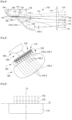
- FIG. 4 is a schematic longitudinal sectional view of a light module according to the second embodiment.
- the light module 102 comprises, similarly to the first embodiment, a first light source 104, an associated first reflective surface 106 and an associated auxiliary reflective surface 108, called a folding surface, with a front cut-off edge 110 for forming a first light beam 116 with a higher horizontal cut-off.
- the light module 102 also comprises a second light source 118 and an associated second reflective surface 120 for forming a second light beam 122.
- the length (along the optical axis) of the second reflecting surface 120 is advantageously shorter, so as to form light images of reduced height, as a complementary beam.
- This second light beam 122 has a lower horizontal cutoff formed essentially by the rear edge 120.1 of the second reflecting surface which is imaged by the projection lens 114.
- This is in this case plano-convex, it being understood that other configurations are possible.
- a convergence optical system 126 is optically arranged between the second light source 118 and the second reflecting surface 120. It is configured to concentrate the light rays emitted by the second light source 118 towards the rear edge 120.1 of the second reflecting surface 120.
- the convergence optical system 126 is in this case a series of lenses arranged opposite each of the light zones of the second light source 118.
- the light module 102 comprises a third light source 128 arranged in front of the second light source 118. It illuminates in the same direction as the first and second light sources, in this case vertically downwards considering the orientation of the Figure 4 where the optical axis 112 is horizontal.
- a third reflecting surface 130 is arranged in front of the second reflecting surface 120, preferably adjacent to said second reflecting surface 120. Similar to the second reflecting surface 120, the third reflecting surface 130 advantageously has a profile of the elliptical or parabolic type. It is advantageously a surface of revolution around an axis parallel to, or coincident with, the optical axis. Alternatively, it may be a free-form surface or a swept surface or an asymmetrical surface. It may also comprise several sectors or segments.
- the third light source 128 is arranged at a focus of the third reflecting surface 130 so that its rays are collected and reflected along the optical axis 112. At least a portion of these reflected rays may have inclination angles ⁇ in a vertical plane relative to said axis which are less than or equal to 25°, preferably less than or equal to 10°, so as to be in the so-called Gaussian conditions. These are advantageously the rays reflected by the portion rear of the third reflecting surface 130.
- the third light source 128, the third reflecting surface 130 and the projection lens 114 thus form a third light beam also with a lower horizontal cut-off, located above the second light beam 122.
- the sharpness of the horizontal cutoffs depends on the positioning of the focus 114.1 of the projection lens 114. If it is at the rear edge 120.1 of the second reflecting surface 120, or at least close to it, the cutoff of the second beam 122 will be sharp. If it is located further forward, at a distance from said rear edge 120.1, the sharpness of the cutoff of the second beam 122 will decrease, on the other hand the sharpness of the cutoff of the third beam 132 will increase as the distance between the focus and the rear edge 130.1 of the third reflecting surface decreases. As already mentioned in relation to the first embodiment, the sharpness of the horizontal cutoffs will also depend on the depth of field of the projection lens 114.
- FIG. 5 is a perspective representation of the reflective surfaces 106, 120 and 130, and of the second and third light sources 118 and 128. It can be seen that each of the second and third light sources 118 and 128 has a series of transversely distributed light zones, individually activatable, in correspondence with the transverse segmentation of the second and third reflective surfaces 120 and 130 into reflective surface strips 120.3 and 130.3.
- the converging optical system 126 comprises a series of converging lenses, each of which is optically arranged between one of the luminous zones of the second light source 118 and the corresponding reflective surface strip 120.3 of the second reflective surface 120.
- FIG. 6 schematically illustrates the light images of the first, second and third light beams 116, 122 and 132.
- the first beam 116 is a beam with a higher horizontal cutoff, in this case along the neutral horizontal axis H. It can thus be a lighting beam of the code type (commonly called “low beam”) or a part of such a beam.
- the second beam 122 consists of an addition of sub-beams each corresponding to one of the light zones of the second light source and to the corresponding reflective surface strip. These sub-beams are laterally adjacent.
- the second beam 122 makes it possible to supplement the first beam 116 in order to form a dipped beam. Selective activation of the sub-beams makes it possible to form an overall beam with a cut-off with a step.
- the third light beam 132 is similar to the second light beam 122, except that it is located above it and has a greater height.
- the sub-beams of the second and third beams are in this case aligned but can be offset transversely.
- the second and third light beams 122 and 132 may be, in combination with the first beam 116, a road type lighting beam (commonly called “high-beam”) of the segmented type, that is to say, transversely modulated by activating the useful light zones of the second and third light sources.
- THE figures 7 to 9 illustrate a third embodiment of the invention.
- the reference numbers of the second embodiment are used to designate identical or corresponding elements, these numbers being increased by 100. Reference is also made to the description of these elements in relation to the second embodiment.
- the third embodiment has a similarity to the second embodiment and is distinguished therefrom essentially by the absence of the first light beam with a higher horizontal cutoff and the components that produce it.
- the second and third light beams of the second embodiment then become the first and second light beams of the third embodiment.
- FIG. 7 is a schematic view in longitudinal section of a light module according to the third embodiment of the invention.
- the light module 202 comprises a first light source 218 and an associated first reflective surface 220 configured to collect and reflect the light rays along the optical axis 212 where at least a portion of these reflected rays have inclination angles ⁇ in a vertical plane relative to said axis which are less than or equal to 25°, preferably less than or equal to 10°, so as to be in the so-called Gaussian conditions, making it possible to obtain stigmatism, that is to say a sharpness of the projected image.
- the first light source 218 and the first reflective surface 220 then produce with the projection lens 214 a first light beam 222 with a lower horizontal cutoff.
- the light module 202 further comprises a second light source 228 and an associated second reflecting surface 230 configured to collect and reflect the light rays along the optical axis 212 where at least a portion of these reflected rays have inclination angles ⁇ in a vertical plane relative to said axis which are less than or equal to 25°, preferably less than or equal to 10°, so as to also be in the so-called Gaussian conditions.
- the second light source 228 and the second reflecting surface 220 then produce with the projection lens 214 a second light beam 232 with a lower horizontal cutoff, located above the first light beam 222.
- the sharpness of the horizontal cutoffs depends on the positioning of the focus 214.1 of the projection lens 214. If this is at the rear edge 220.1 of the first reflecting surface 220, or at least close to it, the cutoff of the first beam 222 will be sharp. If it is located further forward, at a distance from said rear edge 220.1, the sharpness of the cutoff of the first beam 222 will decrease, on the other hand the sharpness of the cutoff of the second beam 132 will increase as the distance between the focus and the rear edge 130.1 of the second reflecting surface decreases.
- FIG 8 is a perspective representation of the reflective surfaces 220 and 230, and the second and third light sources 118 and 128.
- each of the second and third light sources 118 and 128 has a series of light zones distributed transversely, individually activatable, in correspondence with the transverse segmentation of the second and third reflective surfaces 220 and 230 into reflective surface strips 220.3 and 230.3.
- the first beam 122 consists of an addition of sub-beams each corresponding to one of the light zones of the first light source and to the corresponding reflective surface strip. These sub-beams are laterally adjacent. They have a common lower horizontal cut-off, in this case parallel to the neutral horizontal axis H and on or below said axis, produced by the rear edge 220.1 of the first reflective surface 220 ( Figure 7 ). They also have a common upper horizontal cut made by the front edge 220.2 of the first reflective surface 220 ( Figure 7 ).
- the second light beam 232 is similar to the first light beam 222, except that it is located above it and has a greater height.
- the sub-beams of the first and second beams are in this case aligned but can be offset transversely.
- the first beam 222 can, in combination with a beam with a higher horizontal cut-off, produce a dipped beam. Selective activation of the sub-beams makes it possible to form an overall beam with a cut-off with a step.
- the first and second light beams 222 and 232 can produce, in combination with a beam with a higher horizontal cut-off produced by another module, a road-type lighting beam (commonly called “high-beam”) of the matrix type, that is to say, transversely modulated by activating the useful light zones of the second and third light sources.
- high-beam road-type lighting beam
Landscapes
- Engineering & Computer Science (AREA)
- General Engineering & Computer Science (AREA)
- Physics & Mathematics (AREA)
- Microelectronics & Electronic Packaging (AREA)
- Optics & Photonics (AREA)
- Non-Portable Lighting Devices Or Systems Thereof (AREA)
Claims (15)
- Leuchtmodul (2; 102; 202), insbesondere für ein Kraftfahrzeug, umfassend:- eine optische Achse (12; 112; 212);- eine erste Lichtquelle (4; 104; 218), die geeignet ist, Lichtstrahlen zu emittieren, und eine erste reflektierende Fläche (6; 106; 220), die dazu ausgestaltet ist, die von der ersten Lichtquelle emittierten Lichtstrahlen zu sammeln und in einem ersten Lichtbündel (16; 116; 222) zu reflektieren;- eine zweite Lichtquelle (18; 118; 228) und eine zweite reflektierende Fläche (20; 120; 230), die dazu ausgestaltet ist, die von der zweiten Lichtquelle emittierten Lichtstrahlen zu sammeln und in einem zweiten Lichtbündel (22; 122; 232) zu reflektieren;- ein optisches System (14; 114; 214), das dazu ausgestaltet ist, das erste und das zweite Lichtbündel (16, 22; 116, 122; 222, 232) zu projizieren;wobei das optische System (14; 114; 214) einen Brennpunkt beinhaltet, der auf oder in der Nähe der zweiten reflektierenden Fläche (20; 120; 230) gelegen ist, das heißt in einem Abstand von der zweiten reflektierenden Fläche von weniger als 10 mm, und das optische System (14; 114; 214) dazu ausgestaltet ist, ein Bild der zweiten reflektierenden Fläche (20; 120; 230), insbesondere des dem Brennpunkt nächstgelegenen Abschnitts der reflektierenden Fläche, zu bilden, dadurch gekennzeichnet, dassdie erste und die zweite Lichtquelle (4, 18; 104, 118; 218, 228) die Lichtstrahlen in die gleiche Richtung emittieren, dassdie erste und die zweite reflektierende Fläche (6, 20; 106, 120; 220, 230) entlang der optischen Achse (12; 112; 212) versetzt sind, wobei sich die erste reflektierende Fläche (6; 106; 220) hinter der zweiten reflektierenden Fläche (20; 120; 230) befindet, und dassdas erste und das zweite Lichtbündel (16; 116; 222 und 22; 122; 232) entlang der optischen Achse (12; 112; 212) des Moduls emittiert werden.
- Leuchtmodul (2; 102; 202) nach Anspruch 1, dadurch gekennzeichnet, dass die erste und die zweite reflektierende Fläche (4, 18; 104, 118; 218, 228) auf einem selben Kollektor (24; 124; 224) gebildet sind.
- Leuchtmodul (2; 102; 202) nach einem der Ansprüche 1 und 2, dadurch gekennzeichnet, dass die zweite reflektierende Fläche (20; 120; 230) quer zu der optischen Achse (12; 112; 212) segmentiert ist, so dass angrenzende Streifen der reflektierenden Fläche (20.3; 120.3; 230.3) gebildet werden, wobei die zweite Lichtquelle (18; 118; 228) mehrere einzeln aktivierbare Leuchtbereiche umfasst, die sich quer erstrecken und den angrenzenden Streifen der reflektierenden Fläche zugeordnet sind.
- Leuchtmodul (2; 102; 202) nach einem der Ansprüche 1 bis 3, dadurch gekennzeichnet, dass die zweite reflektierende Fläche (20; 120; 230) einen hinteren Rand (20.1; 120.1; 230.1) umfasst, der eine horizontale Hell-Dunkel-Grenze des zweiten Bündels bildet.
- Leuchtmodul (2; 102; 202) nach einem der Ansprüche 1 bis 4, dadurch gekennzeichnet, dass das optische System (14; 114; 214) einen Brennpunkt (14.1; 114.1; 214.1) umfasst, der auf der zweiten reflektierenden Fläche (20; 120; 230) oder in einem Abstand von der zweiten reflektierenden Fläche von weniger als 5 mm gelegen ist.
- Leuchtmodul (2; 102; 202) nach den Ansprüchen 4 und 5, dadurch gekennzeichnet, dass der Brennpunkt (14.1; 114.1; 214.1) des optischen Systems (14; 114; 214) an dem hinteren Rand (20.1; 120.1; 230.1) der zweiten reflektierenden Fläche (20; 120; 230) oder in einem Abstand von dem hinteren Rand von weniger als 10 mm gelegen ist.
- Leuchtmodul (2; 102; 202) nach einem der Ansprüche 1 bis 6, dadurch gekennzeichnet, dass die erste reflektierende Fläche (6; 106; 220) ein elliptisches Profil aufweist und die zweite reflektierende Fläche (20; 120; 230) ein elliptisches oder parabolisches Profil aufweist.
- Leuchtmodul (102) nach einem der Ansprüche 1 bis 7, dadurch gekennzeichnet, dass das Leuchtmodul ferner eine optische Bündelungsvorrichtung (126) umfasst, die optisch zwischen der zweiten Lichtquelle (118) und der zweiten reflektierenden Fläche (120) angeordnet ist und dazu ausgestaltet ist, die von der zweiten Lichtquelle emittierten Lichtstrahlen zu einem hinteren Rand (120.1) der zweiten reflektierenden Fläche (120) hin zu bündeln.
- Leuchtmodul (2; 102) nach einem der Ansprüche 1 bis 8, dadurch gekennzeichnet, dass die erste reflektierende Fläche (6; 106) ein elliptisches Profil mit einem ersten Brennpunkt, wobei die erste Lichtquelle (4; 104) in diesem ersten Brennpunkt gelegen ist, und einem zweiten Brennpunkt hat, wobei das Leuchtmodul ferner eine reflektierende Hilfsfläche (8; 108) mit einem vorderen Rand (10; 110), der an dem zweiten Brennpunkt gelegen ist, umfasst, wobei der vordere Rand einen Rand einer horizontalen Hell-Dunkel-Grenze mit oder ohne Knick des ersten Bündels (16; 116) bildet.
- Leuchtmodul (2; 102) nach einem der Ansprüche 4 und 6 und nach Anspruch 9, dadurch gekennzeichnet, dass der hintere Rand (20.1; 120.1) der zweiten reflektierenden Fläche (20; 120) an den Rand einer horizontalen Hell-Dunkel-Grenze mit oder ohne Knick (10; 110) des ersten Bündels (16; 116) angrenzt oder damit zusammenfällt.
- Leuchtmodul (102) nach einem der Ansprüche 9 und 10, dadurch gekennzeichnet, dass das Leuchtmodul ferner eine dritte Lichtquelle (128) umfasst, die geeignet ist, Lichtstrahlen zu emittieren, und eine dritte reflektierende Fläche (130), die an der Vorderseite der zweiten reflektierenden Fläche (120) an diese angrenzt und dazu ausgestaltet ist, die von der dritten Lichtquelle emittierten Lichtstrahlen zu sammeln und in einem dritten Lichtbündel (132) entlang der optischen Achse (112) zu reflektieren.
- Leuchtmodul (102) nach Anspruch 11, dadurch gekennzeichnet, dass die dritte reflektierende Fläche (130) einen hinteren Rand (130.1) umfasst, der eine horizontale Hell-Dunkel-Grenze des dritten Bündels (132) bildet.
- Leuchtmodul (102) nach einem der Ansprüche 11 und 12, dadurch gekennzeichnet, dass die dritte reflektierende Fläche (130) quer zu der optischen Achse (112) segmentiert ist, so dass angrenzende Streifen der reflektierenden Fläche (130.3) gebildet werden, wobei die dritte Lichtquelle (128) mehrere einzeln aktivierbare Leuchtbereiche umfasst, die sich quer erstrecken und den angrenzenden Streifen der reflektierenden Fläche zugeordnet sind.
- Leuchtmodul (202) nach einem der Ansprüche 1 bis 8, dadurch gekennzeichnet, dass die erste reflektierende Fläche (220) an der Rückseite der zweiten reflektierenden Fläche (230) an diese angrenzt und das optische System (214) dazu ausgestaltet ist, auch ein Bild der ersten reflektierenden Fläche (220) zu bilden.
- Leuchtmodul (202) nach Anspruch 14, dadurch gekennzeichnet, dass die erste reflektierende Fläche (220) quer zu der optischen Achse (212) segmentiert ist, so dass angrenzende Streifen der reflektierenden Fläche (230.3) gebildet werden, wobei die erste Lichtquelle (218) mehrere einzeln aktivierbare Leuchtbereiche umfasst, die sich quer erstrecken und den angrenzenden Streifen der reflektierenden Fläche zugeordnet sind.
Applications Claiming Priority (2)
| Application Number | Priority Date | Filing Date | Title |
|---|---|---|---|
| FR1912908A FR3103253B1 (fr) | 2019-11-19 | 2019-11-19 | Module lumineux combine imageant la surface eclairée d’un collecteur |
| PCT/EP2020/082607 WO2021099430A1 (fr) | 2019-11-19 | 2020-11-18 | Module lumineux combine imageant la surface eclairée d'un collecteur |
Publications (2)
| Publication Number | Publication Date |
|---|---|
| EP4062098A1 EP4062098A1 (de) | 2022-09-28 |
| EP4062098B1 true EP4062098B1 (de) | 2025-04-16 |
Family
ID=70613840
Family Applications (1)
| Application Number | Title | Priority Date | Filing Date |
|---|---|---|---|
| EP20808114.1A Active EP4062098B1 (de) | 2019-11-19 | 2020-11-18 | Kombiniertes leuchtmodul zur abbildung der beleuchteten fläche eines kollektors |
Country Status (5)
| Country | Link |
|---|---|
| US (1) | US11959610B2 (de) |
| EP (1) | EP4062098B1 (de) |
| CN (2) | CN114981590B (de) |
| FR (1) | FR3103253B1 (de) |
| WO (1) | WO2021099430A1 (de) |
Families Citing this family (8)
| Publication number | Priority date | Publication date | Assignee | Title |
|---|---|---|---|---|
| FR3124844B1 (fr) * | 2021-06-30 | 2023-06-30 | Valeo Vision | Module d’éclairage automobile vertical avec aspects éclairés jour et nuit identiques |
| FR3138497B1 (fr) * | 2022-07-28 | 2024-10-18 | Valeo Vision | Module lumineux pour dispositif d’éclairage d’un véhicule |
| FR3138499B1 (fr) * | 2022-07-28 | 2024-10-18 | Valeo Vision | Unité lumineuse de module lumineux d’un véhicule automobile |
| FR3138500B1 (fr) * | 2022-07-28 | 2024-10-18 | Valeo Vision | Unité lumineuse d’un module lumineux d’un véhicule |
| CN219140586U (zh) * | 2022-11-28 | 2023-06-06 | 法雷奥照明湖北技术中心有限公司 | 照明装置和机动车辆 |
| CN219140588U (zh) * | 2022-12-22 | 2023-06-06 | 法雷奥照明湖北技术中心有限公司 | 光学照射组件、照明设备以及机动车辆 |
| CN219530639U (zh) * | 2022-12-27 | 2023-08-15 | 法雷奥照明湖北技术中心有限公司 | 发光装置、机动车辆前照灯和机动车辆 |
| FR3159003A1 (fr) * | 2024-02-07 | 2025-08-08 | Valeo Vision | Module optique d’un dispositif lumineux d’un véhicule automobile. |
Family Cites Families (22)
| Publication number | Priority date | Publication date | Assignee | Title |
|---|---|---|---|---|
| JP2945376B1 (ja) * | 1998-05-01 | 1999-09-06 | スタンレー電気株式会社 | 灯 具 |
| JP4669434B2 (ja) * | 2006-04-24 | 2011-04-13 | 株式会社小糸製作所 | 車両用前照灯 |
| JP2008123753A (ja) * | 2006-11-09 | 2008-05-29 | Koito Mfg Co Ltd | 車両用灯具ユニット |
| JP2009301980A (ja) * | 2008-06-17 | 2009-12-24 | Koito Mfg Co Ltd | 灯具ユニット |
| DE102010013821B4 (de) * | 2010-04-03 | 2016-09-15 | Volkswagen Ag | Leuchtenvorrichtung und Verfahren zur Erzeugung einer ersten und einer zweiten Lichtfunktion für ein Fahrzeug |
| JP2013222553A (ja) * | 2012-04-13 | 2013-10-28 | Koito Mfg Co Ltd | 車両用灯具 |
| US20140362572A1 (en) * | 2013-06-06 | 2014-12-11 | National Central University | Led lighting device with high-low beams |
| JP6271183B2 (ja) * | 2013-08-12 | 2018-01-31 | 株式会社小糸製作所 | 車両用灯具 |
| TWI563219B (en) * | 2013-10-28 | 2016-12-21 | Epistar Corp | Illumination system having semiconductor light source module |
| TWI577584B (zh) * | 2014-02-24 | 2017-04-11 | 王正 | 車燈結構 |
| JP6410341B2 (ja) | 2014-05-23 | 2018-10-24 | 株式会社小糸製作所 | 車両用前照灯 |
| EP3179158A4 (de) * | 2014-08-07 | 2018-03-21 | Koito Manufacturing Co., Ltd. | Scheinwerfer für fahrzeuge |
| JP2016076389A (ja) * | 2014-10-07 | 2016-05-12 | 株式会社小糸製作所 | 車両用灯具 |
| KR101717686B1 (ko) * | 2015-05-12 | 2017-03-20 | 에스엘 주식회사 | 차량용 헤드램프 |
| CN105889840B (zh) * | 2016-06-08 | 2018-03-02 | 广东雷腾智能光电有限公司 | 一种自适应远近光一体led多模组前照灯 |
| JP6792427B2 (ja) * | 2016-11-22 | 2020-11-25 | 株式会社小糸製作所 | 車両用灯具 |
| SI25394A (sl) * | 2017-03-01 | 2018-09-28 | Hella Saturnus Slovenija d.o.o. | Prednji žaromet vozila |
| FR3065786B1 (fr) * | 2017-04-27 | 2019-11-29 | Valeo Vision | Module lumineux pour vehicule automobile |
| JP6884042B2 (ja) * | 2017-06-07 | 2021-06-09 | 株式会社小糸製作所 | 車両用灯具 |
| EP3805634A4 (de) * | 2018-06-01 | 2022-01-26 | Ichikoh Industries, Ltd. | Fahrzeuglampe |
| US10655809B1 (en) * | 2019-06-26 | 2020-05-19 | North American Lighting, Inc. | Vehicle lamp |
| KR102883492B1 (ko) * | 2020-08-13 | 2025-11-11 | 에스엘 주식회사 | 차량용 램프 |
-
2019
- 2019-11-19 FR FR1912908A patent/FR3103253B1/fr active Active
-
2020
- 2020-11-18 WO PCT/EP2020/082607 patent/WO2021099430A1/fr not_active Ceased
- 2020-11-18 US US17/777,799 patent/US11959610B2/en active Active
- 2020-11-18 EP EP20808114.1A patent/EP4062098B1/de active Active
- 2020-11-18 CN CN202080093904.7A patent/CN114981590B/zh active Active
- 2020-11-18 CN CN202411377925.8A patent/CN119196575A/zh active Pending
Also Published As
| Publication number | Publication date |
|---|---|
| FR3103253B1 (fr) | 2021-11-19 |
| EP4062098A1 (de) | 2022-09-28 |
| US11959610B2 (en) | 2024-04-16 |
| US20220412529A1 (en) | 2022-12-29 |
| WO2021099430A1 (fr) | 2021-05-27 |
| CN114981590A (zh) | 2022-08-30 |
| CN119196575A (zh) | 2024-12-27 |
| CN114981590B (zh) | 2024-11-12 |
| FR3103253A1 (fr) | 2021-05-21 |
Similar Documents
| Publication | Publication Date | Title |
|---|---|---|
| EP4062098B1 (de) | Kombiniertes leuchtmodul zur abbildung der beleuchteten fläche eines kollektors | |
| EP4235024B1 (de) | Leuchtvorrichtung, die die beleuchteten flächen von mindestens zwei kollektoren abbildet | |
| EP3830474A1 (de) | Leuchtmodul zur abbildung der beleuchteten fläche eines kollektors | |
| EP4264122B1 (de) | Beleuchtungsvorrichtung für ein kfz | |
| EP3517827B1 (de) | Leuchtmodul, das ein primäres optisches modul umfasst, das mit zwei formgebungsmatten ausgestattet ist | |
| EP3708905B1 (de) | Beleuchtungsvorrichtung zur abbildung eines gespiegelten bilds eines kollektors | |
| EP4264120A1 (de) | Kraftfahrzeugscheinwerfer mit mehreren beleuchtungsmodulen auf einer geneigten gemeinsamen platte | |
| EP3521692B1 (de) | Bifunktions-leuchtmodul mit gemeinsamer beleuchteter fläche | |
| EP4285051B1 (de) | Kraftfahrzeugvorrichtung zur beleuchtung der strasse | |
| WO2022129420A1 (fr) | Module lumineux imageant la surface eclairee d'un collecteur avec bloqueur de rayons parasites | |
| EP4264123B1 (de) | Beleuchtungsvorrichtung mit doppelfunktion und rotierender linse | |
| EP2436968B1 (de) | Vorrichtung zur Ausstrahlung von Licht für einen Autoscheinwerfer | |
| FR3042846A1 (fr) | Dispositif lumineux a guides optiques | |
| EP3128225B1 (de) | Beleuchtungssystem für kfz-scheinwerfer, das ein beleuchtungsmodul mit reduziertem platzbedarf umfasst | |
| EP3575675B1 (de) | Beleuchtungsmodul zur erzeugung einer hell-dunkel-grenze mit einem "zwei zonen" reflektor | |
| EP4500074B1 (de) | Lichtmodul mit einer die beleuchtete fläche eines kollektors abbildenden linse und einem streuende direktstrahlen blockierenden schirm | |
| WO2024133404A1 (fr) | Dispositif lumineux comprenant une pluralité de modules | |
| WO2023006947A1 (fr) | Module d'eclairage de vehicule automobile | |
| FR2999273A1 (fr) | Dispositif d'eclairage et/ou de signalisation pour vehicule automobile, comprenant un cache rotatif |
Legal Events
| Date | Code | Title | Description |
|---|---|---|---|
| STAA | Information on the status of an ep patent application or granted ep patent |
Free format text: STATUS: UNKNOWN |
|
| STAA | Information on the status of an ep patent application or granted ep patent |
Free format text: STATUS: THE INTERNATIONAL PUBLICATION HAS BEEN MADE |
|
| PUAI | Public reference made under article 153(3) epc to a published international application that has entered the european phase |
Free format text: ORIGINAL CODE: 0009012 |
|
| STAA | Information on the status of an ep patent application or granted ep patent |
Free format text: STATUS: REQUEST FOR EXAMINATION WAS MADE |
|
| 17P | Request for examination filed |
Effective date: 20220504 |
|
| AK | Designated contracting states |
Kind code of ref document: A1 Designated state(s): AL AT BE BG CH CY CZ DE DK EE ES FI FR GB GR HR HU IE IS IT LI LT LU LV MC MK MT NL NO PL PT RO RS SE SI SK SM TR |
|
| DAV | Request for validation of the european patent (deleted) | ||
| DAX | Request for extension of the european patent (deleted) | ||
| P01 | Opt-out of the competence of the unified patent court (upc) registered |
Effective date: 20230528 |
|
| STAA | Information on the status of an ep patent application or granted ep patent |
Free format text: STATUS: EXAMINATION IS IN PROGRESS |
|
| 17Q | First examination report despatched |
Effective date: 20240315 |
|
| GRAP | Despatch of communication of intention to grant a patent |
Free format text: ORIGINAL CODE: EPIDOSNIGR1 |
|
| STAA | Information on the status of an ep patent application or granted ep patent |
Free format text: STATUS: GRANT OF PATENT IS INTENDED |
|
| INTG | Intention to grant announced |
Effective date: 20241205 |
|
| GRAS | Grant fee paid |
Free format text: ORIGINAL CODE: EPIDOSNIGR3 |
|
| GRAA | (expected) grant |
Free format text: ORIGINAL CODE: 0009210 |
|
| STAA | Information on the status of an ep patent application or granted ep patent |
Free format text: STATUS: THE PATENT HAS BEEN GRANTED |
|
| AK | Designated contracting states |
Kind code of ref document: B1 Designated state(s): AL AT BE BG CH CY CZ DE DK EE ES FI FR GB GR HR HU IE IS IT LI LT LU LV MC MK MT NL NO PL PT RO RS SE SI SK SM TR |
|
| REG | Reference to a national code |
Ref country code: GB Ref legal event code: FG4D Free format text: NOT ENGLISH |
|
| REG | Reference to a national code |
Ref country code: CH Ref legal event code: EP Ref country code: DE Ref legal event code: R096 Ref document number: 602020049628 Country of ref document: DE |
|
| REG | Reference to a national code |
Ref country code: IE Ref legal event code: FG4D Free format text: LANGUAGE OF EP DOCUMENT: FRENCH |
|
| REG | Reference to a national code |
Ref country code: NL Ref legal event code: MP Effective date: 20250416 |
|
| PG25 | Lapsed in a contracting state [announced via postgrant information from national office to epo] |
Ref country code: NL Free format text: LAPSE BECAUSE OF FAILURE TO SUBMIT A TRANSLATION OF THE DESCRIPTION OR TO PAY THE FEE WITHIN THE PRESCRIBED TIME-LIMIT Effective date: 20250416 |
|
| REG | Reference to a national code |
Ref country code: AT Ref legal event code: MK05 Ref document number: 1785896 Country of ref document: AT Kind code of ref document: T Effective date: 20250416 |
|
| PG25 | Lapsed in a contracting state [announced via postgrant information from national office to epo] |
Ref country code: FI Free format text: LAPSE BECAUSE OF FAILURE TO SUBMIT A TRANSLATION OF THE DESCRIPTION OR TO PAY THE FEE WITHIN THE PRESCRIBED TIME-LIMIT Effective date: 20250416 Ref country code: PT Free format text: LAPSE BECAUSE OF FAILURE TO SUBMIT A TRANSLATION OF THE DESCRIPTION OR TO PAY THE FEE WITHIN THE PRESCRIBED TIME-LIMIT Effective date: 20250818 Ref country code: ES Free format text: LAPSE BECAUSE OF FAILURE TO SUBMIT A TRANSLATION OF THE DESCRIPTION OR TO PAY THE FEE WITHIN THE PRESCRIBED TIME-LIMIT Effective date: 20250416 |
|
| REG | Reference to a national code |
Ref country code: LT Ref legal event code: MG9D |
|
| PG25 | Lapsed in a contracting state [announced via postgrant information from national office to epo] |
Ref country code: NO Free format text: LAPSE BECAUSE OF FAILURE TO SUBMIT A TRANSLATION OF THE DESCRIPTION OR TO PAY THE FEE WITHIN THE PRESCRIBED TIME-LIMIT Effective date: 20250716 Ref country code: GR Free format text: LAPSE BECAUSE OF FAILURE TO SUBMIT A TRANSLATION OF THE DESCRIPTION OR TO PAY THE FEE WITHIN THE PRESCRIBED TIME-LIMIT Effective date: 20250717 |
|
| PG25 | Lapsed in a contracting state [announced via postgrant information from national office to epo] |
Ref country code: PL Free format text: LAPSE BECAUSE OF FAILURE TO SUBMIT A TRANSLATION OF THE DESCRIPTION OR TO PAY THE FEE WITHIN THE PRESCRIBED TIME-LIMIT Effective date: 20250416 |
|
| PG25 | Lapsed in a contracting state [announced via postgrant information from national office to epo] |
Ref country code: BG Free format text: LAPSE BECAUSE OF FAILURE TO SUBMIT A TRANSLATION OF THE DESCRIPTION OR TO PAY THE FEE WITHIN THE PRESCRIBED TIME-LIMIT Effective date: 20250416 |
|
| PG25 | Lapsed in a contracting state [announced via postgrant information from national office to epo] |
Ref country code: HR Free format text: LAPSE BECAUSE OF FAILURE TO SUBMIT A TRANSLATION OF THE DESCRIPTION OR TO PAY THE FEE WITHIN THE PRESCRIBED TIME-LIMIT Effective date: 20250416 |
|
| PG25 | Lapsed in a contracting state [announced via postgrant information from national office to epo] |
Ref country code: AT Free format text: LAPSE BECAUSE OF FAILURE TO SUBMIT A TRANSLATION OF THE DESCRIPTION OR TO PAY THE FEE WITHIN THE PRESCRIBED TIME-LIMIT Effective date: 20250416 |
|
| PG25 | Lapsed in a contracting state [announced via postgrant information from national office to epo] |
Ref country code: RS Free format text: LAPSE BECAUSE OF FAILURE TO SUBMIT A TRANSLATION OF THE DESCRIPTION OR TO PAY THE FEE WITHIN THE PRESCRIBED TIME-LIMIT Effective date: 20250716 |
|
| PG25 | Lapsed in a contracting state [announced via postgrant information from national office to epo] |
Ref country code: IS Free format text: LAPSE BECAUSE OF FAILURE TO SUBMIT A TRANSLATION OF THE DESCRIPTION OR TO PAY THE FEE WITHIN THE PRESCRIBED TIME-LIMIT Effective date: 20250816 |
|
| PG25 | Lapsed in a contracting state [announced via postgrant information from national office to epo] |
Ref country code: LV Free format text: LAPSE BECAUSE OF FAILURE TO SUBMIT A TRANSLATION OF THE DESCRIPTION OR TO PAY THE FEE WITHIN THE PRESCRIBED TIME-LIMIT Effective date: 20250416 |
|
| PGFP | Annual fee paid to national office [announced via postgrant information from national office to epo] |
Ref country code: DE Payment date: 20251117 Year of fee payment: 6 |
|
| PG25 | Lapsed in a contracting state [announced via postgrant information from national office to epo] |
Ref country code: SM Free format text: LAPSE BECAUSE OF FAILURE TO SUBMIT A TRANSLATION OF THE DESCRIPTION OR TO PAY THE FEE WITHIN THE PRESCRIBED TIME-LIMIT Effective date: 20250416 Ref country code: DK Free format text: LAPSE BECAUSE OF FAILURE TO SUBMIT A TRANSLATION OF THE DESCRIPTION OR TO PAY THE FEE WITHIN THE PRESCRIBED TIME-LIMIT Effective date: 20250416 |
|
| PGFP | Annual fee paid to national office [announced via postgrant information from national office to epo] |
Ref country code: FR Payment date: 20251128 Year of fee payment: 6 |
|
| REG | Reference to a national code |
Ref country code: DE Ref legal event code: R097 Ref document number: 602020049628 Country of ref document: DE |
|
| PG25 | Lapsed in a contracting state [announced via postgrant information from national office to epo] |
Ref country code: CZ Free format text: LAPSE BECAUSE OF FAILURE TO SUBMIT A TRANSLATION OF THE DESCRIPTION OR TO PAY THE FEE WITHIN THE PRESCRIBED TIME-LIMIT Effective date: 20250416 |
|
| PG25 | Lapsed in a contracting state [announced via postgrant information from national office to epo] |
Ref country code: EE Free format text: LAPSE BECAUSE OF FAILURE TO SUBMIT A TRANSLATION OF THE DESCRIPTION OR TO PAY THE FEE WITHIN THE PRESCRIBED TIME-LIMIT Effective date: 20250416 |
|
| PG25 | Lapsed in a contracting state [announced via postgrant information from national office to epo] |
Ref country code: SK Free format text: LAPSE BECAUSE OF FAILURE TO SUBMIT A TRANSLATION OF THE DESCRIPTION OR TO PAY THE FEE WITHIN THE PRESCRIBED TIME-LIMIT Effective date: 20250416 |
|
| PG25 | Lapsed in a contracting state [announced via postgrant information from national office to epo] |
Ref country code: IT Free format text: LAPSE BECAUSE OF FAILURE TO SUBMIT A TRANSLATION OF THE DESCRIPTION OR TO PAY THE FEE WITHIN THE PRESCRIBED TIME-LIMIT Effective date: 20250416 |
|
| PG25 | Lapsed in a contracting state [announced via postgrant information from national office to epo] |
Ref country code: RO Free format text: LAPSE BECAUSE OF FAILURE TO SUBMIT A TRANSLATION OF THE DESCRIPTION OR TO PAY THE FEE WITHIN THE PRESCRIBED TIME-LIMIT Effective date: 20250416 |
|
| PLBE | No opposition filed within time limit |
Free format text: ORIGINAL CODE: 0009261 |
|
| STAA | Information on the status of an ep patent application or granted ep patent |
Free format text: STATUS: NO OPPOSITION FILED WITHIN TIME LIMIT |
|
| REG | Reference to a national code |
Ref country code: CH Ref legal event code: L10 Free format text: ST27 STATUS EVENT CODE: U-0-0-L10-L00 (AS PROVIDED BY THE NATIONAL OFFICE) Effective date: 20260225 |
|
| 26N | No opposition filed |
Effective date: 20260119 |