EP4264123B1 - Beleuchtungsvorrichtung mit doppelfunktion und rotierender linse - Google Patents
Beleuchtungsvorrichtung mit doppelfunktion und rotierender linse Download PDFInfo
- Publication number
- EP4264123B1 EP4264123B1 EP21854808.9A EP21854808A EP4264123B1 EP 4264123 B1 EP4264123 B1 EP 4264123B1 EP 21854808 A EP21854808 A EP 21854808A EP 4264123 B1 EP4264123 B1 EP 4264123B1
- Authority
- EP
- European Patent Office
- Prior art keywords
- lighting device
- optical system
- light beam
- optical
- light
- Prior art date
- Legal status (The legal status is an assumption and is not a legal conclusion. Google has not performed a legal analysis and makes no representation as to the accuracy of the status listed.)
- Active
Links
Images
Classifications
-
- F—MECHANICAL ENGINEERING; LIGHTING; HEATING; WEAPONS; BLASTING
- F21—LIGHTING
- F21S—NON-PORTABLE LIGHTING DEVICES; SYSTEMS THEREOF; VEHICLE LIGHTING DEVICES SPECIALLY ADAPTED FOR VEHICLE EXTERIORS
- F21S41/00—Illuminating devices specially adapted for vehicle exteriors, e.g. headlamps
- F21S41/20—Illuminating devices specially adapted for vehicle exteriors, e.g. headlamps characterised by refractors, transparent cover plates, light guides or filters
- F21S41/25—Projection lenses
-
- F—MECHANICAL ENGINEERING; LIGHTING; HEATING; WEAPONS; BLASTING
- F21—LIGHTING
- F21S—NON-PORTABLE LIGHTING DEVICES; SYSTEMS THEREOF; VEHICLE LIGHTING DEVICES SPECIALLY ADAPTED FOR VEHICLE EXTERIORS
- F21S41/00—Illuminating devices specially adapted for vehicle exteriors, e.g. headlamps
- F21S41/10—Illuminating devices specially adapted for vehicle exteriors, e.g. headlamps characterised by the light source
- F21S41/14—Illuminating devices specially adapted for vehicle exteriors, e.g. headlamps characterised by the light source characterised by the type of light source
- F21S41/141—Light emitting diodes [LED]
- F21S41/147—Light emitting diodes [LED] the main emission direction of the LED being angled to the optical axis of the illuminating device
- F21S41/148—Light emitting diodes [LED] the main emission direction of the LED being angled to the optical axis of the illuminating device the main emission direction of the LED being perpendicular to the optical axis
-
- F—MECHANICAL ENGINEERING; LIGHTING; HEATING; WEAPONS; BLASTING
- F21—LIGHTING
- F21S—NON-PORTABLE LIGHTING DEVICES; SYSTEMS THEREOF; VEHICLE LIGHTING DEVICES SPECIALLY ADAPTED FOR VEHICLE EXTERIORS
- F21S41/00—Illuminating devices specially adapted for vehicle exteriors, e.g. headlamps
- F21S41/30—Illuminating devices specially adapted for vehicle exteriors, e.g. headlamps characterised by reflectors
- F21S41/32—Optical layout thereof
- F21S41/321—Optical layout thereof the reflector being a surface of revolution or a planar surface, e.g. truncated
-
- F—MECHANICAL ENGINEERING; LIGHTING; HEATING; WEAPONS; BLASTING
- F21—LIGHTING
- F21S—NON-PORTABLE LIGHTING DEVICES; SYSTEMS THEREOF; VEHICLE LIGHTING DEVICES SPECIALLY ADAPTED FOR VEHICLE EXTERIORS
- F21S41/00—Illuminating devices specially adapted for vehicle exteriors, e.g. headlamps
- F21S41/60—Illuminating devices specially adapted for vehicle exteriors, e.g. headlamps characterised by a variable light distribution
- F21S41/63—Illuminating devices specially adapted for vehicle exteriors, e.g. headlamps characterised by a variable light distribution by acting on refractors, filters or transparent cover plates
- F21S41/635—Illuminating devices specially adapted for vehicle exteriors, e.g. headlamps characterised by a variable light distribution by acting on refractors, filters or transparent cover plates by moving refractors, filters or transparent cover plates
-
- F—MECHANICAL ENGINEERING; LIGHTING; HEATING; WEAPONS; BLASTING
- F21—LIGHTING
- F21S—NON-PORTABLE LIGHTING DEVICES; SYSTEMS THEREOF; VEHICLE LIGHTING DEVICES SPECIALLY ADAPTED FOR VEHICLE EXTERIORS
- F21S43/00—Signalling devices specially adapted for vehicle exteriors, e.g. brake lamps, direction indicator lights or reversing lights
- F21S43/10—Signalling devices specially adapted for vehicle exteriors, e.g. brake lamps, direction indicator lights or reversing lights characterised by the light source
- F21S43/13—Signalling devices specially adapted for vehicle exteriors, e.g. brake lamps, direction indicator lights or reversing lights characterised by the light source characterised by the type of light source
- F21S43/14—Light emitting diodes [LED]
-
- F—MECHANICAL ENGINEERING; LIGHTING; HEATING; WEAPONS; BLASTING
- F21—LIGHTING
- F21S—NON-PORTABLE LIGHTING DEVICES; SYSTEMS THEREOF; VEHICLE LIGHTING DEVICES SPECIALLY ADAPTED FOR VEHICLE EXTERIORS
- F21S43/00—Signalling devices specially adapted for vehicle exteriors, e.g. brake lamps, direction indicator lights or reversing lights
- F21S43/40—Signalling devices specially adapted for vehicle exteriors, e.g. brake lamps, direction indicator lights or reversing lights characterised by the combination of reflectors and refractors
-
- F—MECHANICAL ENGINEERING; LIGHTING; HEATING; WEAPONS; BLASTING
- F21—LIGHTING
- F21W—INDEXING SCHEME ASSOCIATED WITH SUBCLASSES F21K, F21L, F21S and F21V, RELATING TO USES OR APPLICATIONS OF LIGHTING DEVICES OR SYSTEMS
- F21W2102/00—Exterior vehicle lighting devices for illuminating purposes
- F21W2102/10—Arrangement or contour of the emitted light
- F21W2102/13—Arrangement or contour of the emitted light for high-beam region or low-beam region
- F21W2102/135—Arrangement or contour of the emitted light for high-beam region or low-beam region the light having cut-off lines, i.e. clear borderlines between emitted regions and dark regions
- F21W2102/155—Arrangement or contour of the emitted light for high-beam region or low-beam region the light having cut-off lines, i.e. clear borderlines between emitted regions and dark regions having inclined and horizontal cutoff lines
-
- F—MECHANICAL ENGINEERING; LIGHTING; HEATING; WEAPONS; BLASTING
- F21—LIGHTING
- F21W—INDEXING SCHEME ASSOCIATED WITH SUBCLASSES F21K, F21L, F21S and F21V, RELATING TO USES OR APPLICATIONS OF LIGHTING DEVICES OR SYSTEMS
- F21W2103/00—Exterior vehicle lighting devices for signalling purposes
- F21W2103/55—Daytime running lights [DRL]
Definitions
- the invention relates to the field of lighting and light signaling, in particular for motor vehicles.
- Such a light module conventionally comprises a collector with a reflective surface of revolution with an elliptical profile, in the shape of a cap in a half-space delimited by a horizontal plane.
- An essentially point light source, of the electroluminescent diode type is located at a first focus of the reflective surface and illuminates in the half-space in the direction of said surface. The rays are thus reflected in a convergent manner towards a second focus of the reflective surface.
- Another generally flat reflective surface with a cut-off edge at the second focus, ensures an upward reflection of the rays which do not pass precisely through the second focus, these rays then being refracted by a thick lens towards the bottom of the lighting beam.
- This reflective surface is commonly referred to as a "folder” in that it "folds" towards the top of the projection lens the rays which would otherwise form an upper part of the lighting beam.
- Such a light module has the disadvantage of requiring high precision in the positioning of the folder and the cutting edge.
- the projection lens must be a thick lens due to its short focal length, which increases its weight and complicates its production, such as shrinkage defects.
- the collector has a certain height and, therefore, a certain height requirement.
- the published patent document WO 2020/025171 A1 discloses a light module in particular for a motor vehicle, comprising a collector with a reflective surface collecting and reflecting the light rays emitted by a light source into a light beam, similar to a folding light module.
- the light module also comprises an optical projection system, such as a lens, specifically configured to project the light beam in question by forming an image of the reflective surface of the collector.
- the optical projection system has a focus located on the reflective surface, for example at a rear edge thereof, so as to correctly image said edge and form a cut-off clear in the projected light beam.
- This type of light module has the advantages of compactness, particularly in height, and simplicity of production. They can be combined to form different light beams which add up.
- the invention aims to overcome at least one of the drawbacks of the aforementioned state of the art. More particularly, the invention aims to propose a lighting device which integrates a maximum of lighting functions.
- the invention relates to a light device for a motor vehicle, comprising one or more light sources capable of emitting light rays; one or more collectors each with a reflective surface configured to collect and reflect the light rays emitted by the one or more light sources, called reflected light rays, into a reflected light beam along an optical axis; an optical system comprising a projection lens performing a first optical function performing the projection of at least the majority of the reflected light beam into a projected light beam by imaging a portion of the or each reflective surface located, along a general direction of propagation of the light beam, behind the or each corresponding light source; remarkable in that the optical system comprises an additional portion distinct from the projection lens and performing a second optical function performing a diffusion of at least the majority of the reflected light beam into a diffused light beam, said optical system being rotatable about an axis of rotation between a first position where the first function is active and a second position where the second function is active.
- the collector can be a concave reflector.
- At least some of the reflected rays have angles of inclination relative to the optical axis that are less than or equal to 10°. This allows for so-called Gaussian conditions, thus allowing stigmatism.
- the additional part is formed by one or more diffusing screens, the or each diffusing screen being crossed by at least the majority of the reflected light beam when the optical system is in the second position, the at least majority of the reflected light beam being diffused after having crossed said screen to form the diffused light beam.
- the projection lens has a focal zone located on the reflecting surface of the or each of the corresponding collectors, at a rear edge of said reflecting surface. This simply makes it possible to image the part of the part of the reflecting surface located at the rear of the light source.
- the focal zone is located at a rear edge of said reflecting surface.
- this focal zone can be a focal point, also called a focus, or can be a focal line, also called a line of focuses.
- the optical system comprises an optical part comprising the projection lens and the additional part, the lighting device comprising a mechanism for rotating said optical part around the axis of rotation.
- said optical part is a transparent part.
- the optical part comprises a first input face and a first output face associated with the first input face, corresponding to the projection lens, and a second input face and a second output face associated with the second input face, corresponding to the additional part, the first and second input faces and/or the first and second output faces being angularly offset around the axis of rotation by an angle of between 60° and 120°.
- the second output face has an average height, perpendicular to the axis of rotation, greater than an average height, perpendicular to the axis of rotation, of the first output face.
- the first output face has an average height, perpendicular to the axis of rotation, less than 10 mm.
- the first input face in the first position of the optical system, is positioned facing the one or more collectors, and in the second position, the second input face is positioned facing the one or more collectors.
- the axis of rotation of the optical system is transverse to the optical axis and horizontal when the lighting device is in the operational position.
- the optical part is elongated along the axis of rotation.
- the rotation of the optical system between the first and second functions has an angular amplitude of between 60° and 120°.
- the light beam projected in the first position of the optical system is a lighting beam and the light beam diffused in the second position of the optical system is a signaling beam or a light signature.
- a light signature is a light beam having an aesthetic light function which would make it possible to identify the model and/or make of the vehicle in all circumstances.
- the light device comprises several light sources and several collectors with several reflecting surfaces so as to form several added reflected light beams, and in which the optical system is rotatable between the first position where the projection lens receives at least the majority of said reflected light beams and a second position where the additional part receives at least the majority of said reflected light beams.
- each of the at least one light source, the at least one collector and the at least one reflective surface is multiple so as to selectively form several light beams that add together.
- the multiple collectors, reflective surfaces and light sources are arranged side by side.
- the first function of the optical system comprises a focal line passing through the reflective surfaces, more advantageously through the rear edges of said reflective surfaces, or between said reflective surfaces and the corresponding light sources.
- the second function of said optical system forms a light beam from light rays emitted by one or more auxiliary light sources.
- the measures of the invention are interesting in that they make it possible to integrate at least one additional light function into a lighting device, without actually increasing the necessary volume.
- the light sources present in the device for the lighting function(s) can be used for the additional function.
- the [ fig.1 ] is a perspective view of a lighting device according to the invention.
- the lighting device 2 is, here, a selectively lighting and signaling device, as will be detailed below.
- the lighting device 2 comprises a housing 4 itself being able to consist of a series of components or housing portions, assembled to each other.
- the housing 4 comprises several optical cavities with light sources 6.1, 6.2, 6.3 and reflective surfaces 8.1, 8.2 and 8.3.
- the lighting device also comprises an optical system 10 capable of receiving and shaping the light beams in question.
- the optical system 10 comprises an optical part 12 with a dual function, namely a first optical projection function and a second optical light diffusion function.
- the optical part 12 is mounted to rotate about an axis of rotation 14 so as to activate, selectively, one or the other of the first and second functions.
- the lighting device 2 comprises a mechanism 16 for rotating said optical part 12 about the axis of rotation 14. This mechanism may comprise an electric motor coupled to an angle return mechanism itself coupled to the optical part.
- the second light diffusion function is activated, meaning that the light beams produced by the light sources and associated reflective surfaces will be diffused in order to provide a signaling function.
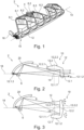
- FIGS. 2 and 3 illustrate schematically and in longitudinal section the lighting device of the [ fig.1 ] in the first and second functions, respectively. More specifically, these figures illustrate a single light source and a single reflective surface associated with the light source, it being understood that they apply to each of the light sources and associated reflective surfaces.
- fig.2 illustrates the light device 2 when the optical device is in the first position where the first optical function of projecting the light beam is active.
- the optical part 12 comprises a first portion 12.1 corresponding to the first function and a second portion 12.2 corresponding to the second function.
- the first portion 12.1 of the optical part 12 is active by being arranged facing the light rays emitted by the light source 6 and reflected by the reflecting surface 8, while the second portion 12.2 is inactive by being arranged at a distance from the rays in question.
- these two portions each have a generally elongated cross section, these two cross sections forming an elbow with an angle close to the order of 90°, advantageously between 70° and 100°.
- These cross sections in principle have different geometries given their different optical functions.
- the first portion 12.1 of the optical part 12, ensuring the first function forms a projection lens with an input face 12.1.1 and an input face 12.1.2.
- This lens may in particular be of the plano-convex or biconvex type.
- the second portion 12.2 of the optical part 12, ensuring the second function also comprises an input face 12.2 1 and an output face 12.2.2.
- the first portion 12.1 is formed by a projection lens while the second portion 12.2 is here formed by an additional part distinct from the projection lens.
- the light source 6 is advantageously of the semiconductor type, such as in particular a light-emitting diode.
- the light source 6 emits light rays in a half-space delimited by the main plane of said source, according to the example shown, in a main direction perpendicular to said plane and to the optical axis 18.
- the main emission direction may be between 65° and 115° relative to the optical axis 18.
- a collector 20 forms a shell-shaped or cap-shaped support, on the inner face of which the reflecting surface 8 is applied.
- the reflecting surface 8 advantageously has an elliptical or parabolic profile. It is advantageously a surface of revolution about an axis parallel to the optical axis. Alternatively, it may be a free-form surface or a swept surface or an asymmetrical surface. It may also comprise several sectors.
- the shell-shaped or cap-shaped collector 20 is advantageously made of materials having good heat resistance, for example glass or synthetic polymers such as polycarbonate PC or polyetherimide PEI.
- the expression "parabolic type" generally applies to reflectors whose surface has a single focus, i.e.
- a parabolic surface may therefore have parabolic portions or not.
- a reflector with such a surface is generally used alone to create a light beam. Alternatively, it can be used as a projection surface associated with an elliptical reflector. In this case, the light source of the parabolic reflector is the convergence zone of the rays reflected by the elliptical reflector.
- the light source 6 is arranged at a focus of the reflecting surface 8 of such that its rays are collected and reflected along the optical axis, said rays, called reflected rays, forming a reflected light beam. At least part of these reflected rays have angles of inclination a in a vertical plane relative to said axis which are less than or equal to 25°, preferably less than or equal to 10°, so as to be in the so-called Gaussian conditions, making it possible to obtain a stigmatism, that is to say a sharpness of the projected image. These are advantageously the rays reflected by the rear part of the reflecting surface 8.
- the first portion 12.1 of the optical part 12, forming the projection lens has a focus 12.1.3 which is located along the optical axis 18, at the level of the light source 6 or behind said source.
- the focus 12.1.3 is located on the reflecting surface 8, at a rear edge, here also lower edge, thereof. It should be noted that it is also possible for this focus to be located at the rear or at the front of the reflecting surface 8, preferably nearby, in particular less than 10 mm, preferably less than 5 mm.
- the first portion 12.1 described is configured to project at least the majority of the reflected light beam into a projected light beam performing a lighting light function.
- fig.3 illustrates the light device 2 when the optical device is in the second position where the second optical function of diffusing the light beam is active.
- the optical part has undergone a rotation about its rotation axis 14 of the order of 90°, in this case in the anti-clockwise direction, so as to make the first portion 12.1 inactive and the second portion 12.2 active.
- the input face 12.2.1 of the second portion 12.2 intersects with the optical axis 18 and is located opposite the reflecting surface 8 and the light source 6, so as to collect the light beam produced by the latter, also called the reflected light beam.
- At least one of the input 12.2.1 and output 12.2.2 faces may have a rough or grained surface so as to provide a light diffusion function.
- the second portion 12.2 is configured to project at least the majority of the reflected light beam into a diffusing light beam which here performs a light signaling function.
- the input face 12.2.1 of the second portion 12.2 of the optical part 12 is at a distance from the reflecting surface 8 that is potentially different from that of the input face 12.1.1 of the first portion 12.1 (when the latter is in the active position).
- the function of the second function of the optical system is not to image the reflecting surface 8 illuminated by the light source 6 like the first function.
- the second function consists of diffusing the light in order to provide a signaling function.
- the input face 12.2.1 of the second portion 12.2 is higher (in a direction perpendicular to the optical axis when the function is active) than the input face 12.1.1 of the first portion 12.1, allowing it to collect more rays reflected by the reflecting surface 8.
- auxiliary light sources for the second function, i.e. inactive for the first function.
- the second function described above may be, for example, a signaling function that is not necessary when the motor vehicle is moving.
- it may be a function such as a position light or lantern, or a light signature, activated when the vehicle is parked or stopped for a long time.
- the optical system 10 may be common to several collectors, reflecting surfaces and associated light sources, arranged side by side.
- the first function may then have not a point focus but a focus line passing through the rear parts of the reflecting surfaces in question.
- the focus line in question may not be rectilinear, in this case slightly curved.
Landscapes
- Engineering & Computer Science (AREA)
- General Engineering & Computer Science (AREA)
- Physics & Mathematics (AREA)
- Microelectronics & Electronic Packaging (AREA)
- Optics & Photonics (AREA)
- Non-Portable Lighting Devices Or Systems Thereof (AREA)
Claims (10)
- Leuchtvorrichtung (2) für ein Kraftfahrzeug, umfassend:• eine oder mehrere Lichtquellen (6), die geeignet sind, Lichtstrahlen zu emittieren;• einen oder mehrere Kollektoren (20) mit einer reflektierenden Oberfläche (8), wobei die oder jede reflektierende Oberfläche dazu ausgestaltet ist, die von der oder einer der mehreren Lichtquellen (6) emittierten Lichtstrahlen, reflektierte Lichtstrahlen genannt, zu sammeln und in ein entlang einer optischen Achse (18) reflektiertes Lichtbündel zu reflektieren;• ein optisches System (10), das eine Projektionslinse (12.1) umfasst, die eine erste optische Funktion ausführt, die die Projektion mindestens der Mehrheit des reflektierten Lichtbündels in ein projiziertes Lichtbündel ausführt, indem ein Teil der oder jeder reflektierenden Oberfläche (8) abgebildet wird, der entlang einer Hauptausbreitungsrichtung des Lichtbündels hinter der oder jeder entsprechenden Lichtquelle (6) gelegen ist;dadurch gekennzeichnet, dass das optische System (10) einen zusätzlichen Teil (12.2) umfasst, der von der Projektionslinse verschieden ist und eine zweite optische Funktion ausführt, die eine Streuung mindestens der Mehrheit des reflektierten Lichtbündels in ein gestreutes Lichtbündel ausführt, wobei das optische System um eine Drehachse (14) herum zwischen einer ersten Stellung, in der die erste Funktion aktiv ist, und einer zweiten Stellung, in der die zweite Funktion aktiv ist, drehbar ist.
- Leuchtvorrichtung (2) nach Anspruch 1, wobei der zusätzliche Teil (12.2) durch einen oder mehrere streuende Schirme gebildet wird, wobei der oder jeder streuende Schirm von mindestens der Mehrheit des reflektierten Lichtbündels durchquert wird, wenn das optische System (10) in der zweiten Stellung ist, wobei mindestens die Mehrheit des reflektierten Lichtbündels gestreut wird, nachdem es den Schirm durchquert hat, um das gestreute Lichtbündel zu bilden.
- Leuchtvorrichtung (2) nach einem der Ansprüche 1 und 2, wobei die Projektionslinse (12.1) einen Fokusbereich (12.1.3) aufweist, der auf der reflektierenden Oberfläche des oder jedes der entsprechenden Kollektoren, an einem hinteren Rand der reflektierenden Oberfläche, gelegen ist.
- Leuchtvorrichtung (2) nach einem der Ansprüche 1 bis 3, wobei das optische System (10) ein optisches Teil (12) umfasst, das die Projektionslinse und den zusätzlichen Teil umfasst, wobei die Leuchtvorrichtung (2) einen Drehmechanismus (16) zum Drehen des optischen Teils (12) um die Drehachse (14) herum umfasst.
- Leuchtvorrichtung (2) nach einem der vorhergehenden Ansprüche, wobei das optische Teil (12) eine erste Eintrittsseite (12.1.1) und eine der ersten Eintrittsseite (12.1.1) zugeordnete erste Austrittsseite (12.1.2), der Projektionslinse (12.1) entsprechend, und eine zweite Eintrittsseite (12.2.1) und eine der zweiten Eintrittsseite (12.2.1) zugeordnete zweite Austrittsseite (12.2.2), dem zusätzlichen Teil (12.2) entsprechend, umfasst, und wobei die ersten und zweiten Eintrittsseiten (12.1.1, 12.2.1) und/oder die ersten und zweiten Austrittsseiten (12.1.2, 12.2.2) winklig um die Drehachse (14) herum um einen Winkel zwischen 60° und 120° versetzt sind.
- Leuchtvorrichtung (2) nach dem vorhergehenden Anspruch, wobei, in der ersten Stellung des optischen Systems (10), die erste Eintrittsseite (12.1.1) gegenüber dem oder den mehreren Kollektoren (20) positioniert ist und, in der zweiten Stellung des optischen Systems (10), die zweite Eintrittsseite (12.2.1) gegenüber dem oder den mehreren Kollektoren (20) positioniert ist.
- Leuchtvorrichtung (2) nach einem der vorhergehenden Ansprüche, wobei die Drehachse (14) des optischen Systems (10) quer zu der optischen Achse (18) und horizontal verläuft, wenn die Leuchtvorrichtung (2) in der Betriebsstellung ist.
- Leuchtvorrichtung (2) nach einem der vorhergehenden Ansprüche, wobei das in der ersten Stellung des optischen Systems (10) projizierte Lichtbündel ein Beleuchtungsbündel ist und das in der zweiten Stellung des optischen Systems (10) gestreute Lichtbündel ein Signalisierungsbündel oder eine Leuchtsignatur ist.
- Leuchtvorrichtung (2) nach einem der vorhergehenden Ansprüche, wobei die Leuchtvorrichtung mehrere Lichtquellen (6) und mehrere Kollektoren (20) mit mehreren reflektierenden Oberflächen (8) umfasst, so dass mehrere sich addierende reflektierte Lichtbündel gebildet werden, und wobei das optische System (10) zwischen der ersten Stellung, in der die Projektionslinse (12.1) mindestens die Mehrheit der reflektierten Lichtbündel empfängt, und einer zweiten Stellung, in welcher der zusätzliche Teil (12.2) mindestens die Mehrheit der reflektierten Lichtbündel empfängt, drehbar ist.
- Leuchtvorrichtung (2) nach einem der vorhergehenden Ansprüche, wobei, in der zweiten Stellung des optischen Systems (10), die zweite Funktion des optischen Systems ein Lichtbündel ausgehend von Lichtstrahlen bildet, die von einer oder mehreren sekundären Lichtquellen emittiert werden.
Applications Claiming Priority (2)
| Application Number | Priority Date | Filing Date | Title |
|---|---|---|---|
| FR2013753A FR3118127B1 (fr) | 2020-12-18 | 2020-12-18 | Dispositif lumineux bi-fonction avec lentille rotative |
| PCT/EP2021/086330 WO2022129427A1 (fr) | 2020-12-18 | 2021-12-16 | Dispositif lumineux bi-fonction avec lentille rotative |
Publications (2)
| Publication Number | Publication Date |
|---|---|
| EP4264123A1 EP4264123A1 (de) | 2023-10-25 |
| EP4264123B1 true EP4264123B1 (de) | 2024-11-13 |
Family
ID=74554137
Family Applications (1)
| Application Number | Title | Priority Date | Filing Date |
|---|---|---|---|
| EP21854808.9A Active EP4264123B1 (de) | 2020-12-18 | 2021-12-16 | Beleuchtungsvorrichtung mit doppelfunktion und rotierender linse |
Country Status (4)
| Country | Link |
|---|---|
| EP (1) | EP4264123B1 (de) |
| CN (1) | CN116648579A (de) |
| FR (1) | FR3118127B1 (de) |
| WO (1) | WO2022129427A1 (de) |
Families Citing this family (2)
| Publication number | Priority date | Publication date | Assignee | Title |
|---|---|---|---|---|
| FR3139375B1 (fr) * | 2022-09-06 | 2024-10-04 | Valeo Vision | Module d’éclairage route avec source lumineuse dirigée vers le haut |
| CN120274230B (zh) * | 2025-04-11 | 2025-10-21 | 永林电子股份有限公司 | 一种警示车用贯穿灯总成 |
Family Cites Families (13)
| Publication number | Priority date | Publication date | Assignee | Title |
|---|---|---|---|---|
| WO1996016294A1 (en) * | 1994-11-17 | 1996-05-30 | Cunningham, David, W. | Lighting device incorporating a zoomable beamspreader |
| DE102004002280A1 (de) * | 2004-01-16 | 2005-08-25 | Automotive Lighting Reutlingen Gmbh | Scheinwerferanordnung |
| KR101054662B1 (ko) * | 2004-12-17 | 2011-08-08 | 현대자동차주식회사 | 차속 감지형 능동 등화장치 |
| JP2009151221A (ja) * | 2007-12-21 | 2009-07-09 | Seiko Epson Corp | 照明装置、画像表示装置及び偏光変換拡散部材 |
| JP5435379B2 (ja) * | 2012-10-26 | 2014-03-05 | スタンレー電気株式会社 | 車両用前照灯 |
| FR3016567B1 (fr) * | 2014-01-17 | 2016-01-29 | Peugeot Citroen Automobiles Sa | Dispositif d'eclairage reversible pour vehicule automobile |
| FR3016568B1 (fr) * | 2014-01-17 | 2016-01-29 | Peugeot Citroen Automobiles Sa | Dispositif d'eclairage a lentille mobile pour vehicule automobile |
| JP2016115582A (ja) * | 2014-12-16 | 2016-06-23 | 株式会社小糸製作所 | 配光デバイスを備えた車両用灯具 |
| WO2017086439A1 (ja) * | 2015-11-20 | 2017-05-26 | 大日本印刷株式会社 | 照明装置 |
| FR3084728B1 (fr) | 2018-07-31 | 2021-03-19 | Valeo Vision | Module lumineux imageant la surface eclairee d'un collecteur |
| FR3093789B1 (fr) * | 2019-03-14 | 2022-05-27 | Valeo Vision | Dispositif lumineux imageant les surfaces eclairees d’au moins deux collecteurs |
| FR3093788B1 (fr) * | 2019-03-14 | 2022-05-27 | Valeo Vision | Dispositif lumineux imageant une surface eclairee virtuelle d’un collecteur |
| CN111486404B (zh) * | 2020-04-17 | 2022-04-26 | 东风汽车有限公司 | 前组合车灯 |
-
2020
- 2020-12-18 FR FR2013753A patent/FR3118127B1/fr active Active
-
2021
- 2021-12-16 CN CN202180083938.2A patent/CN116648579A/zh active Pending
- 2021-12-16 EP EP21854808.9A patent/EP4264123B1/de active Active
- 2021-12-16 WO PCT/EP2021/086330 patent/WO2022129427A1/fr not_active Ceased
Also Published As
| Publication number | Publication date |
|---|---|
| WO2022129427A1 (fr) | 2022-06-23 |
| EP4264123A1 (de) | 2023-10-25 |
| CN116648579A (zh) | 2023-08-25 |
| FR3118127B1 (fr) | 2022-12-16 |
| FR3118127A1 (fr) | 2022-06-24 |
Similar Documents
| Publication | Publication Date | Title |
|---|---|---|
| EP3708904B1 (de) | Leuchtvorrichtung, die die beleuchteten flächen von mindestens zwei kollektoren abbildet | |
| EP4062098B1 (de) | Kombiniertes leuchtmodul zur abbildung der beleuchteten fläche eines kollektors | |
| WO2020025171A1 (fr) | Module lumineux imageant la surface eclairee d'un collecteur | |
| EP4264122B1 (de) | Beleuchtungsvorrichtung für ein kfz | |
| EP3167226B1 (de) | Beleuchtungsmodul für ein kraftfahrzeug | |
| EP4264120A1 (de) | Kraftfahrzeugscheinwerfer mit mehreren beleuchtungsmodulen auf einer geneigten gemeinsamen platte | |
| EP3708905B1 (de) | Beleuchtungsvorrichtung zur abbildung eines gespiegelten bilds eines kollektors | |
| FR3010772A1 (fr) | Dispositif d'emission de lumiere pour projecteur de vehicule automobile | |
| EP4264123B1 (de) | Beleuchtungsvorrichtung mit doppelfunktion und rotierender linse | |
| EP2976569B1 (de) | Beleuchtungs- und/oder meldemodul für ein kraftfahrzeug | |
| WO2022129420A1 (fr) | Module lumineux imageant la surface eclairee d'un collecteur avec bloqueur de rayons parasites | |
| EP3141806B1 (de) | Leuchtmodul aus transparentem material | |
| EP2302292A1 (de) | Optisches Modul mit Falzmaschine, das aus einem Diopter für transparentes Material/Luft gebildet wird | |
| EP4569262A1 (de) | Scheinwerfer mit vertikaler hell-dunkel-grenze und verlängerung für ein kraftfahrzeug | |
| EP3575675B1 (de) | Beleuchtungsmodul zur erzeugung einer hell-dunkel-grenze mit einem "zwei zonen" reflektor | |
| EP4500074B1 (de) | Lichtmodul mit einer die beleuchtete fläche eines kollektors abbildenden linse und einem streuende direktstrahlen blockierenden schirm | |
| EP3502553A1 (de) | Beleuchtungsvorrichtung für ein kraftfahrzeug | |
| WO2023006947A1 (fr) | Module d'eclairage de vehicule automobile | |
| WO2024133404A1 (fr) | Dispositif lumineux comprenant une pluralité de modules |
Legal Events
| Date | Code | Title | Description |
|---|---|---|---|
| STAA | Information on the status of an ep patent application or granted ep patent |
Free format text: STATUS: UNKNOWN |
|
| STAA | Information on the status of an ep patent application or granted ep patent |
Free format text: STATUS: THE INTERNATIONAL PUBLICATION HAS BEEN MADE |
|
| PUAI | Public reference made under article 153(3) epc to a published international application that has entered the european phase |
Free format text: ORIGINAL CODE: 0009012 |
|
| STAA | Information on the status of an ep patent application or granted ep patent |
Free format text: STATUS: REQUEST FOR EXAMINATION WAS MADE |
|
| 17P | Request for examination filed |
Effective date: 20230718 |
|
| AK | Designated contracting states |
Kind code of ref document: A1 Designated state(s): AL AT BE BG CH CY CZ DE DK EE ES FI FR GB GR HR HU IE IS IT LI LT LU LV MC MK MT NL NO PL PT RO RS SE SI SK SM TR |
|
| DAV | Request for validation of the european patent (deleted) | ||
| DAX | Request for extension of the european patent (deleted) | ||
| GRAP | Despatch of communication of intention to grant a patent |
Free format text: ORIGINAL CODE: EPIDOSNIGR1 |
|
| STAA | Information on the status of an ep patent application or granted ep patent |
Free format text: STATUS: GRANT OF PATENT IS INTENDED |
|
| INTG | Intention to grant announced |
Effective date: 20240612 |
|
| GRAS | Grant fee paid |
Free format text: ORIGINAL CODE: EPIDOSNIGR3 |
|
| GRAA | (expected) grant |
Free format text: ORIGINAL CODE: 0009210 |
|
| STAA | Information on the status of an ep patent application or granted ep patent |
Free format text: STATUS: THE PATENT HAS BEEN GRANTED |
|
| AK | Designated contracting states |
Kind code of ref document: B1 Designated state(s): AL AT BE BG CH CY CZ DE DK EE ES FI FR GB GR HR HU IE IS IT LI LT LU LV MC MK MT NL NO PL PT RO RS SE SI SK SM TR |
|
| REG | Reference to a national code |
Ref country code: GB Ref legal event code: FG4D Free format text: NOT ENGLISH |
|
| REG | Reference to a national code |
Ref country code: CH Ref legal event code: EP |
|
| REG | Reference to a national code |
Ref country code: DE Ref legal event code: R096 Ref document number: 602021021918 Country of ref document: DE |
|
| REG | Reference to a national code |
Ref country code: IE Ref legal event code: FG4D Free format text: LANGUAGE OF EP DOCUMENT: FRENCH |
|
| REG | Reference to a national code |
Ref country code: LT Ref legal event code: MG9D |
|
| REG | Reference to a national code |
Ref country code: NL Ref legal event code: MP Effective date: 20241113 |
|
| P01 | Opt-out of the competence of the unified patent court (upc) registered |
Free format text: CASE NUMBER: APP_8352/2025 Effective date: 20250219 |
|
| PG25 | Lapsed in a contracting state [announced via postgrant information from national office to epo] |
Ref country code: HR Free format text: LAPSE BECAUSE OF FAILURE TO SUBMIT A TRANSLATION OF THE DESCRIPTION OR TO PAY THE FEE WITHIN THE PRESCRIBED TIME-LIMIT Effective date: 20241113 Ref country code: PT Free format text: LAPSE BECAUSE OF FAILURE TO SUBMIT A TRANSLATION OF THE DESCRIPTION OR TO PAY THE FEE WITHIN THE PRESCRIBED TIME-LIMIT Effective date: 20250313 Ref country code: IS Free format text: LAPSE BECAUSE OF FAILURE TO SUBMIT A TRANSLATION OF THE DESCRIPTION OR TO PAY THE FEE WITHIN THE PRESCRIBED TIME-LIMIT Effective date: 20250313 |
|
| PG25 | Lapsed in a contracting state [announced via postgrant information from national office to epo] |
Ref country code: NL Free format text: LAPSE BECAUSE OF FAILURE TO SUBMIT A TRANSLATION OF THE DESCRIPTION OR TO PAY THE FEE WITHIN THE PRESCRIBED TIME-LIMIT Effective date: 20241113 Ref country code: FI Free format text: LAPSE BECAUSE OF FAILURE TO SUBMIT A TRANSLATION OF THE DESCRIPTION OR TO PAY THE FEE WITHIN THE PRESCRIBED TIME-LIMIT Effective date: 20241113 |
|
| REG | Reference to a national code |
Ref country code: AT Ref legal event code: MK05 Ref document number: 1741918 Country of ref document: AT Kind code of ref document: T Effective date: 20241113 |
|
| PG25 | Lapsed in a contracting state [announced via postgrant information from national office to epo] |
Ref country code: BG Free format text: LAPSE BECAUSE OF FAILURE TO SUBMIT A TRANSLATION OF THE DESCRIPTION OR TO PAY THE FEE WITHIN THE PRESCRIBED TIME-LIMIT Effective date: 20241113 |
|
| PG25 | Lapsed in a contracting state [announced via postgrant information from national office to epo] |
Ref country code: ES Free format text: LAPSE BECAUSE OF FAILURE TO SUBMIT A TRANSLATION OF THE DESCRIPTION OR TO PAY THE FEE WITHIN THE PRESCRIBED TIME-LIMIT Effective date: 20241113 |
|
| PG25 | Lapsed in a contracting state [announced via postgrant information from national office to epo] |
Ref country code: NO Free format text: LAPSE BECAUSE OF FAILURE TO SUBMIT A TRANSLATION OF THE DESCRIPTION OR TO PAY THE FEE WITHIN THE PRESCRIBED TIME-LIMIT Effective date: 20250213 |
|
| PG25 | Lapsed in a contracting state [announced via postgrant information from national office to epo] |
Ref country code: LV Free format text: LAPSE BECAUSE OF FAILURE TO SUBMIT A TRANSLATION OF THE DESCRIPTION OR TO PAY THE FEE WITHIN THE PRESCRIBED TIME-LIMIT Effective date: 20241113 Ref country code: GR Free format text: LAPSE BECAUSE OF FAILURE TO SUBMIT A TRANSLATION OF THE DESCRIPTION OR TO PAY THE FEE WITHIN THE PRESCRIBED TIME-LIMIT Effective date: 20250214 Ref country code: AT Free format text: LAPSE BECAUSE OF FAILURE TO SUBMIT A TRANSLATION OF THE DESCRIPTION OR TO PAY THE FEE WITHIN THE PRESCRIBED TIME-LIMIT Effective date: 20241113 |
|
| PG25 | Lapsed in a contracting state [announced via postgrant information from national office to epo] |
Ref country code: PL Free format text: LAPSE BECAUSE OF FAILURE TO SUBMIT A TRANSLATION OF THE DESCRIPTION OR TO PAY THE FEE WITHIN THE PRESCRIBED TIME-LIMIT Effective date: 20241113 |
|
| PGFP | Annual fee paid to national office [announced via postgrant information from national office to epo] |
Ref country code: FR Payment date: 20250131 Year of fee payment: 5 |
|
| PG25 | Lapsed in a contracting state [announced via postgrant information from national office to epo] |
Ref country code: RS Free format text: LAPSE BECAUSE OF FAILURE TO SUBMIT A TRANSLATION OF THE DESCRIPTION OR TO PAY THE FEE WITHIN THE PRESCRIBED TIME-LIMIT Effective date: 20250213 |
|
| PG25 | Lapsed in a contracting state [announced via postgrant information from national office to epo] |
Ref country code: SM Free format text: LAPSE BECAUSE OF FAILURE TO SUBMIT A TRANSLATION OF THE DESCRIPTION OR TO PAY THE FEE WITHIN THE PRESCRIBED TIME-LIMIT Effective date: 20241113 |
|
| PG25 | Lapsed in a contracting state [announced via postgrant information from national office to epo] |
Ref country code: DK Free format text: LAPSE BECAUSE OF FAILURE TO SUBMIT A TRANSLATION OF THE DESCRIPTION OR TO PAY THE FEE WITHIN THE PRESCRIBED TIME-LIMIT Effective date: 20241113 |
|
| PG25 | Lapsed in a contracting state [announced via postgrant information from national office to epo] |
Ref country code: EE Free format text: LAPSE BECAUSE OF FAILURE TO SUBMIT A TRANSLATION OF THE DESCRIPTION OR TO PAY THE FEE WITHIN THE PRESCRIBED TIME-LIMIT Effective date: 20241113 |
|
| PG25 | Lapsed in a contracting state [announced via postgrant information from national office to epo] |
Ref country code: RO Free format text: LAPSE BECAUSE OF FAILURE TO SUBMIT A TRANSLATION OF THE DESCRIPTION OR TO PAY THE FEE WITHIN THE PRESCRIBED TIME-LIMIT Effective date: 20241113 |
|
| PG25 | Lapsed in a contracting state [announced via postgrant information from national office to epo] |
Ref country code: SK Free format text: LAPSE BECAUSE OF FAILURE TO SUBMIT A TRANSLATION OF THE DESCRIPTION OR TO PAY THE FEE WITHIN THE PRESCRIBED TIME-LIMIT Effective date: 20241113 |
|
| PG25 | Lapsed in a contracting state [announced via postgrant information from national office to epo] |
Ref country code: CZ Free format text: LAPSE BECAUSE OF FAILURE TO SUBMIT A TRANSLATION OF THE DESCRIPTION OR TO PAY THE FEE WITHIN THE PRESCRIBED TIME-LIMIT Effective date: 20241113 |
|
| PG25 | Lapsed in a contracting state [announced via postgrant information from national office to epo] |
Ref country code: IT Free format text: LAPSE BECAUSE OF FAILURE TO SUBMIT A TRANSLATION OF THE DESCRIPTION OR TO PAY THE FEE WITHIN THE PRESCRIBED TIME-LIMIT Effective date: 20241113 |
|
| REG | Reference to a national code |
Ref country code: CH Ref legal event code: PL |
|
| REG | Reference to a national code |
Ref country code: DE Ref legal event code: R097 Ref document number: 602021021918 Country of ref document: DE |
|
| PG25 | Lapsed in a contracting state [announced via postgrant information from national office to epo] |
Ref country code: LU Free format text: LAPSE BECAUSE OF NON-PAYMENT OF DUE FEES Effective date: 20241216 |
|
| PG25 | Lapsed in a contracting state [announced via postgrant information from national office to epo] |
Ref country code: SE Free format text: LAPSE BECAUSE OF FAILURE TO SUBMIT A TRANSLATION OF THE DESCRIPTION OR TO PAY THE FEE WITHIN THE PRESCRIBED TIME-LIMIT Effective date: 20241113 |
|
| PG25 | Lapsed in a contracting state [announced via postgrant information from national office to epo] |
Ref country code: MC Free format text: LAPSE BECAUSE OF FAILURE TO SUBMIT A TRANSLATION OF THE DESCRIPTION OR TO PAY THE FEE WITHIN THE PRESCRIBED TIME-LIMIT Effective date: 20241113 |
|
| PLBE | No opposition filed within time limit |
Free format text: ORIGINAL CODE: 0009261 |
|
| STAA | Information on the status of an ep patent application or granted ep patent |
Free format text: STATUS: NO OPPOSITION FILED WITHIN TIME LIMIT |
|
| REG | Reference to a national code |
Ref country code: BE Ref legal event code: MM Effective date: 20241231 |
|
| PG25 | Lapsed in a contracting state [announced via postgrant information from national office to epo] |
Ref country code: BE Free format text: LAPSE BECAUSE OF NON-PAYMENT OF DUE FEES Effective date: 20241231 |
|
| PG25 | Lapsed in a contracting state [announced via postgrant information from national office to epo] |
Ref country code: CH Free format text: LAPSE BECAUSE OF NON-PAYMENT OF DUE FEES Effective date: 20241231 |
|
| 26N | No opposition filed |
Effective date: 20250814 |
|
| PG25 | Lapsed in a contracting state [announced via postgrant information from national office to epo] |
Ref country code: IE Free format text: LAPSE BECAUSE OF NON-PAYMENT OF DUE FEES Effective date: 20241216 |
|
| PGFP | Annual fee paid to national office [announced via postgrant information from national office to epo] |
Ref country code: DE Payment date: 20251231 Year of fee payment: 5 |