EP4062891A1 - Dispositif de massage - Google Patents
Dispositif de massage Download PDFInfo
- Publication number
- EP4062891A1 EP4062891A1 EP21164172.5A EP21164172A EP4062891A1 EP 4062891 A1 EP4062891 A1 EP 4062891A1 EP 21164172 A EP21164172 A EP 21164172A EP 4062891 A1 EP4062891 A1 EP 4062891A1
- Authority
- EP
- European Patent Office
- Prior art keywords
- belt
- massage
- vertical
- massage device
- horizontal
- Prior art date
- Legal status (The legal status is an assumption and is not a legal conclusion. Google has not performed a legal analysis and makes no representation as to the accuracy of the status listed.)
- Granted
Links
Images

Classifications
-
- A—HUMAN NECESSITIES
- A61—MEDICAL OR VETERINARY SCIENCE; HYGIENE
- A61H—PHYSICAL THERAPY APPARATUS, e.g. DEVICES FOR LOCATING OR STIMULATING REFLEX POINTS IN THE BODY; ARTIFICIAL RESPIRATION; MASSAGE; BATHING DEVICES FOR SPECIAL THERAPEUTIC OR HYGIENIC PURPOSES OR SPECIFIC PARTS OF THE BODY
- A61H7/00—Devices for suction-kneading massage; Devices for massaging the skin by rubbing or brushing not otherwise provided for
- A61H7/001—Devices for suction-kneading massage; Devices for massaging the skin by rubbing or brushing not otherwise provided for without substantial movement between the skin and the device
-
- A—HUMAN NECESSITIES
- A61—MEDICAL OR VETERINARY SCIENCE; HYGIENE
- A61H—PHYSICAL THERAPY APPARATUS, e.g. DEVICES FOR LOCATING OR STIMULATING REFLEX POINTS IN THE BODY; ARTIFICIAL RESPIRATION; MASSAGE; BATHING DEVICES FOR SPECIAL THERAPEUTIC OR HYGIENIC PURPOSES OR SPECIFIC PARTS OF THE BODY
- A61H11/00—Belts, strips or combs for massage purposes
-
- A—HUMAN NECESSITIES
- A61—MEDICAL OR VETERINARY SCIENCE; HYGIENE
- A61H—PHYSICAL THERAPY APPARATUS, e.g. DEVICES FOR LOCATING OR STIMULATING REFLEX POINTS IN THE BODY; ARTIFICIAL RESPIRATION; MASSAGE; BATHING DEVICES FOR SPECIAL THERAPEUTIC OR HYGIENIC PURPOSES OR SPECIFIC PARTS OF THE BODY
- A61H23/00—Percussion or vibration massage, e.g. using supersonic vibration; Suction-vibration massage; Massage with moving diaphragms
- A61H23/02—Percussion or vibration massage, e.g. using supersonic vibration; Suction-vibration massage; Massage with moving diaphragms with electric or magnetic drive
- A61H23/0254—Percussion or vibration massage, e.g. using supersonic vibration; Suction-vibration massage; Massage with moving diaphragms with electric or magnetic drive with rotary motor
- A61H23/0263—Percussion or vibration massage, e.g. using supersonic vibration; Suction-vibration massage; Massage with moving diaphragms with electric or magnetic drive with rotary motor using rotating unbalanced masses
-
- A—HUMAN NECESSITIES
- A61—MEDICAL OR VETERINARY SCIENCE; HYGIENE
- A61H—PHYSICAL THERAPY APPARATUS, e.g. DEVICES FOR LOCATING OR STIMULATING REFLEX POINTS IN THE BODY; ARTIFICIAL RESPIRATION; MASSAGE; BATHING DEVICES FOR SPECIAL THERAPEUTIC OR HYGIENIC PURPOSES OR SPECIFIC PARTS OF THE BODY
- A61H2201/00—Characteristics of apparatus not provided for in the preceding codes
- A61H2201/01—Constructive details
- A61H2201/0107—Constructive details modular
-
- A—HUMAN NECESSITIES
- A61—MEDICAL OR VETERINARY SCIENCE; HYGIENE
- A61H—PHYSICAL THERAPY APPARATUS, e.g. DEVICES FOR LOCATING OR STIMULATING REFLEX POINTS IN THE BODY; ARTIFICIAL RESPIRATION; MASSAGE; BATHING DEVICES FOR SPECIAL THERAPEUTIC OR HYGIENIC PURPOSES OR SPECIFIC PARTS OF THE BODY
- A61H2201/00—Characteristics of apparatus not provided for in the preceding codes
- A61H2201/01—Constructive details
- A61H2201/0119—Support for the device
- A61H2201/0138—Support for the device incorporated in furniture
- A61H2201/0149—Seat or chair
-
- A—HUMAN NECESSITIES
- A61—MEDICAL OR VETERINARY SCIENCE; HYGIENE
- A61H—PHYSICAL THERAPY APPARATUS, e.g. DEVICES FOR LOCATING OR STIMULATING REFLEX POINTS IN THE BODY; ARTIFICIAL RESPIRATION; MASSAGE; BATHING DEVICES FOR SPECIAL THERAPEUTIC OR HYGIENIC PURPOSES OR SPECIFIC PARTS OF THE BODY
- A61H2201/00—Characteristics of apparatus not provided for in the preceding codes
- A61H2201/01—Constructive details
- A61H2201/0157—Constructive details portable
-
- A—HUMAN NECESSITIES
- A61—MEDICAL OR VETERINARY SCIENCE; HYGIENE
- A61H—PHYSICAL THERAPY APPARATUS, e.g. DEVICES FOR LOCATING OR STIMULATING REFLEX POINTS IN THE BODY; ARTIFICIAL RESPIRATION; MASSAGE; BATHING DEVICES FOR SPECIAL THERAPEUTIC OR HYGIENIC PURPOSES OR SPECIFIC PARTS OF THE BODY
- A61H2201/00—Characteristics of apparatus not provided for in the preceding codes
- A61H2201/01—Constructive details
- A61H2201/0192—Specific means for adjusting dimensions
-
- A—HUMAN NECESSITIES
- A61—MEDICAL OR VETERINARY SCIENCE; HYGIENE
- A61H—PHYSICAL THERAPY APPARATUS, e.g. DEVICES FOR LOCATING OR STIMULATING REFLEX POINTS IN THE BODY; ARTIFICIAL RESPIRATION; MASSAGE; BATHING DEVICES FOR SPECIAL THERAPEUTIC OR HYGIENIC PURPOSES OR SPECIFIC PARTS OF THE BODY
- A61H2201/00—Characteristics of apparatus not provided for in the preceding codes
- A61H2201/12—Driving means
- A61H2201/1253—Driving means driven by a human being, e.g. hand driven
- A61H2201/1261—Driving means driven by a human being, e.g. hand driven combined with active exercising of the patient
- A61H2201/1284—Driving means driven by a human being, e.g. hand driven combined with active exercising of the patient using own weight
-
- A—HUMAN NECESSITIES
- A61—MEDICAL OR VETERINARY SCIENCE; HYGIENE
- A61H—PHYSICAL THERAPY APPARATUS, e.g. DEVICES FOR LOCATING OR STIMULATING REFLEX POINTS IN THE BODY; ARTIFICIAL RESPIRATION; MASSAGE; BATHING DEVICES FOR SPECIAL THERAPEUTIC OR HYGIENIC PURPOSES OR SPECIFIC PARTS OF THE BODY
- A61H2201/00—Characteristics of apparatus not provided for in the preceding codes
- A61H2201/16—Physical interface with patient
- A61H2201/1657—Movement of interface, i.e. force application means
- A61H2201/168—Movement of interface, i.e. force application means not moving
-
- A—HUMAN NECESSITIES
- A61—MEDICAL OR VETERINARY SCIENCE; HYGIENE
- A61H—PHYSICAL THERAPY APPARATUS, e.g. DEVICES FOR LOCATING OR STIMULATING REFLEX POINTS IN THE BODY; ARTIFICIAL RESPIRATION; MASSAGE; BATHING DEVICES FOR SPECIAL THERAPEUTIC OR HYGIENIC PURPOSES OR SPECIFIC PARTS OF THE BODY
- A61H2205/00—Devices for specific parts of the body
- A61H2205/08—Trunk
- A61H2205/081—Back
Definitions
- the present invention relates to a massage device.
- Back pain is a well-known and widespread ailment that many people suffer from in everyday life and at work.
- the wide spread of back pain can already be determined from a few figures (as of 2020):
- the total costs in Germany for back problems alone are estimated at around 50 billion euros.
- 20% of back patients suffer from chronic back pain, accounting for around 80% of the costs incurred for back problems.
- More than 18 million workers suffer from back pain as a result of their job.
- Well over 70% of them feel that their overall health and well-being are impaired by the condition and that their performance is restricted as a result.
- Sitting as such is not necessarily problematic, only a static long-term sitting without much movement becomes problematic. Static sitting can weaken the muscles in many parts of the body, since the muscles are not being used and therefore atrophy. For example, it is known that the tension that causes back pain is more likely to occur with weakened abdominal and back muscles than with well-trained ones and that a large part of the common back and neck complaints can be attributed to this. Due to lack of exercise, the fasciae also shorten and harden. Lymphatic fluid accumulates in tense muscles, the fiber layers stick together and become rigid and immobile.
- Trigger points which correspond to small muscle hardenings, are caused, among other things, by overloading or poor posture. Trigger points can be either active or latent, i.e. silent. The active trigger point not only causes pain when the muscle is active, but also when it is at rest. A latent trigger point, on the other hand, only causes pain when felt, but it also promotes further muscular imbalances and complaints.
- trigger points With a targeted trigger point therapy, the muscles can be relaxed and pain can be eliminated. Above all, trigger points, which can be felt as a lump and can be reached with the hands or auxiliary equipment, can be alleviated and dissolved by self-treatment.
- the possible uses of trigger point therapy are diverse, for example in the shoulder or arm area and in the entire spinal column area. The different Complaints are often expressed through pain, stiffness, dysfunction or sensory disturbances. The trigger points can be resolved with a short self-treatment.
- the object of the present invention is therefore to address one of the problems mentioned above, to improve the general prior art or to provide an alternative to what was previously known.
- a solution is to be provided with which mobilization of the muscles is made possible and tension and muscle hardening can be reduced.
- a massage device according to claim 1 is proposed.
- the massage device comprises a belt system and at least one massage device.
- the belt system serves as a supporting structure. Objects can be attached to the belt system at any desired position, with the attachment of a massage device or a large number of massage devices being provided on the belt system.
- the belt system has a first and a second vertical belt. It is therefore proposed that the belt system has at least two belts which are different and which are arranged essentially vertically.
- the belt system is accordingly formed from a large number of belts.
- the straps are designed as fabric straps.
- the straps can also be made of another material that has sufficient tear resistance and suitability as a supporting structure, such as leather or plastic straps.
- the first and second vertical chords are spaced apart from one another and each have a first end and a second end.
- the vertical chords are designed to run essentially parallel. It is therefore proposed that the two vertical chords are arranged at a spatial distance from one another, for example parallel, and do not intersect or touch. The vertical chords thus serve as support elements which essentially extend in a vertical direction.
- the belt system has at least one horizontal belt.
- the at least one horizontal belt is therefore aligned essentially horizontally.
- the at least one horizontal chord thus serves as a support element that extends in a horizontal direction.
- the horizontal chord is connected to the first vertical chord at a first connection point.
- the horizontal chord is connected to the second vertical chord at a second connection point.
- the horizontal chord thus connects the first and the second vertical chord. It is therefore proposed that the two vertical chords and the at least one horizontal chord are mechanically connected to one another, for example rigidly or detachably connected.
- the belt system also has a first and a second fastening means for mounting the belts on an assembly object.
- a seat is proposed as a particularly preferred mounting object, for example a seat in a vehicle or on a chair. It is therefore proposed that at least two fastening means are part of the belt system or the massage device in order to connect the belt system to the assembly object or to fix the belt system to the object.
- the fastening means can also be interpreted synonymously as a suspension, since the fastening means are intended to hang up or attach the massage device to the mounting object. The fastening means are therefore used to fix the belts of the belt system to the assembly object.
- the first fastening means is arranged on the respective first ends of the first and second vertical chord.
- the second fastening means is arranged at the respective second end of the first and second vertical strap. It is therefore proposed that the two ends of the respective vertical straps are attached to the assembly object, namely with the fastening means, in particular in such a way that the four end points of the vertical straps maintain their positions on the assembly object and do not slip when performing a trigger massage.
- the fastening means can be part of the vertical chords or a horizontal chord.
- the belt system also includes at least one massage device for trigger massage.
- a means for trigger massage is therefore proposed, it being understood that the massage means accordingly has such a shape which enables a selective massage of trigger points.
- the massage agent has a pebble-like shape for this purpose.
- the massage means forms a closed body and can accordingly also be understood synonymously as a massage unit.
- Several massage devices can also be attached to the belt system, for example three or more.
- the massage means has a belt mount for flat and detachable mounting of a belt of the belt system. It is therefore proposed that the belt holder is designed in such a way that a belt of the belt system can be pushed flat into the belt holder for the massage agent. Thus, for example after the belt system has been fastened to the assembly object by means of the fastening means, the massage means can be fastened or attached to the belts, for example by a vertical belt being pushed flat into the belt receptacle. In addition, the belt holder is designed in such a way that the massage means can also be detached again from the inserted belt.
- the at least one massage means is detachably fastened to the at least one horizontal belt by means of the belt mount. It is therefore proposed that the massage device or devices be attached to the at least one horizontal strap. The massage means is then detachably connected to the horizontal belt, i. H. the position of the massage device on the horizontal belt to which the massage device is attached is adjustable.
- the massage device can be placed at a freely selectable point on a belt of the belt system and the massage device can thus be adapted to the individual trigger points and body characteristics of the user, such as height and width.
- This provides a very flexible and customizable trigger massage system that can be used to effectively and individually treat trigger points.
- the belt system preferably has a large number of horizontal belts, with each horizontal belt being connected to the first vertical belt at a first connection point and to the second vertical belt at a second connection point, in particular in order to be able to place the at least one massage means in different massage positions.
- a plurality of horizontal chords are provided, which are aligned parallel to one another, for example, and are each individually connected to the two vertical chords at a first and a second connection point.
- the belt system consisting of the vertical belts and the multiplicity of horizontal belts can be designed in the form of a ladder.
- the massage means can be removed from a first horizontal strap and hung up again at another location on another horizontal strap.
- a massage device for trigger massage that is particularly easy to adjust is thus provided.
- the massage device preferably comprises a plurality of massage means in order to provide a multi-point massage with a plurality of massage means. It is therefore proposed that several massage means can be attached to the straps of the belt system. Thus, for example, several massage means can be attached to a horizontal belt, or several massage means can be divided among several horizontal belts. Thus, advantageously, several trigger points can be treated at the same time.
- the massage means is dimensionally stable and is made of a dimensionally stable material, in particular the massage means is made of plastic.
- a dimensionally stable material in particular the massage means is made of plastic.
- other dimensionally stable materials can also be provided, such as wood, carbon fiber or natural fiber material.
- Dimensionally stable describes that the massage agent retains its shape when a force is applied, which occurs during a trigger massage and acts on the massage agent.
- the plastic is a biodegradable plastic, preferably a home-compostable plastic.
- the massage means has a cavity or is hollow, with support struts preferably being arranged inside the cavity to maintain the shape of the massage means when a force is applied to the massage means.
- material can be saved and the weight of the massage means can be reduced.
- the mass means remains in shape through the support struts when a force acts on the massage means, for example the force or force effect that occurs during a trigger massage occurs and acts on the massage means during normal use of the massage device.
- the at least one horizontal chord is preferably connected to the first vertical chord at the first connection point via a detachable connection means. Additionally or alternatively, the at least one horizontal chord is connected to the second vertical chord at the second connection point via a detachable connection means. It is therefore proposed that the horizontal strap or straps be releasably connected to the vertical straps, so that the horizontal straps can be attached at any position between the vertical straps.
- the detachable connecting means for connecting the horizontal strap and the vertical straps is designed as a Velcro fastener.
- the horizontal straps can have a Velcro strip with barbs at the two connection points with the vertical straps and the vertical straps can have a Velcro strip with loops at the corresponding connection points.
- the massage means has a curved upper side and a substantially flat underside, with the belt receptacle being arranged in an area on the underside. It is thus proposed that the strap holder is arranged closer to the underside of the massage means.
- this has advantages in terms of mechanical stability and, on the other hand, the arrangement of the belt receptacle on an underside of the massage means increases the massage contact surface on the top side of the massage means. Due to the curved shape of the top, an effective and selective trigger massage can be provided.
- the belts stand out only slightly from the assembly object due to the arrangement of the belt holder on an underside, so that comfortable sitting is still possible.
- the belt receptacle is preferably designed as a wavy belt attachment channel that is open on three sides, in order to provide a planar insertion of a belt of the belt system into the belt attachment channel and around the belt to connect the massage agent detachably.
- the direction of insertion is the direction in which a strap is inserted into the receptacle.
- the waveform of the belt attachment channel preferably extends along the direction of insertion. The waveform serves to increase the friction of the inserted belt in the belt holder, so that the massage agent does not slip when a force is applied to the massage agent.
- the belt fastening channel which is open on three sides, makes it possible for a belt to be easily attached later, after the belt system to which the assembly object has been attached, by pushing the belt flat into the channel that is open on three sides.
- the belt attachment channel has a frontally arranged inclined belt insertion surface in relation to a horizontal axis of the massage means.
- the belt receptacle of the massage means has at least one laterally arranged inclined belt insertion surface in relation to one or the horizontal axis of the massage means.
- the sloping belt insertion surfaces make it easier to insert the belt that is to be inserted into the channel.
- the inclined surfaces serve as a guide for the belt to be inserted.
- a funnel-shaped slide-in guide is thus provided by the sloping surfaces, in order to more easily slide the belt into the belt-fastening channel of the massage means.
- the massage means is preferably set up with a vibration device arranged in an interior area of the massage means for vibration. It is thus proposed that massage means can vibrate to provide particularly effective stimulation at a trigger point to be treated.
- the vibration device of the massage means for generating vibration has at least one chargeable energy store for supplying an electrical vibration unit and a switching means for electrically connecting or disconnecting the vibration unit to the energy store.
- the electrical energy store can be designed, for example, as a chargeable lithium-ion battery.
- the electric vibration unit can be designed as an electric motor, on the shaft of which an unbalance is attached.
- a switching means is also provided for connecting or disconnecting the vibration unit to the energy store.
- a pressure switch or button can be provided as the switching means, for example, on an outside of the massage means.
- the first and additionally or alternatively the second fastening means are preferably designed as length-adjustable straps. It is therefore proposed that the length of the fastening means, which can also be part of the belts of the belt system, be adjustable. This allows the belt system to be adapted for attachment to different sized assembly objects. For example, a ladder buckle or a clamp buckle can be used to change the length.
- the first and the second fastening means are preferably designed with closure elements in such a way that the first end of the first vertical chord can be releasably connected to the first end of the second vertical chord via a first closure element. It is therefore proposed that a possibility be provided to form a fastening loop by connecting the first end of the first vertical strap to the first end of the second vertical strap. This loop can then be attached to an upper area of the assembly object, for example. In a concrete example, the loop can be placed and fixed around the headrest of a seat.
- the second end of the first vertical chord can be detachably connected to the second end of the second vertical chord via a second closure element. It is therefore proposed that a possibility be provided to form a fastening loop by connecting the second end of the first vertical strap to the second end of the second vertical strap. This loop can then be attached to a lower area of the mounting object, for example. In a further specific example, the loop can be placed and fixed around a lower area of a seat.
- first end of the first or second vertical strap can be connected to the second end of the first or second vertical strap via a third closure element. It is thus proposed that a possibility be provided to form a fastening loop by connecting the first end and the second end of a vertical strap. This loop can then be used, for example, to fasten the belt system in a rear area of the assembly object.
- a loop is formed by the mentioned connection, which can be placed along the back of a seat in order to fix the belt system.
- closure elements are designed as snap buckles or the like.
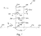
- FIG. 1 schematically shows a massage device 100 in a front view in one embodiment.
- the massage device has a belt system 200 that serves as a support structure for the massage means 300 .
- the belt system 200 has a first and a second vertical belt 210, 212.
- the two vertical belts 210, 212 are spaced apart and are designed to run parallel and each have a first and a second end E1 and E2.
- the belt system 200 also has four horizontal belts 220, 222, 224 and 226 which are arranged horizontally.
- Each of the four horizontal chords is connected to the first vertical chord at a first connection point and to the second vertical chord at a second connection point.
- connection points P1 and P2 for the horizontal belt 220 are shown.
- Each of the horizontal straps 220, 222, 224 and 226 is therefore mechanically connected to the two vertical belts 210 and 212 .
- the belt system 200 also has a first and a second fastening means 230, 232 for mounting the belts on an assembly object, the assembly object not being shown in the figure.
- An exemplary assembly object is in the figure 4 shown, namely a seat of a vehicle.
- the first fastening means 230 is arranged on the respective first ends E1 of the first and second vertical chords 210, 212 and is directly connected to them.
- the fastening element 230 is part of the vertical straps 210, 212 and is designed as a length-adjustable strap.
- the second fastening means 232 is arranged on the respective second ends E2 of the first and second vertical chords 210, 212 and is directly connected to them.
- the fastening element 232 is designed as a length-adjustable belt and has closure elements 242 and 244, which are designed as snap buckles.
- the fastening element 230 has a closure element 240, which is also designed as a snap buckle.
- the massage device 100 also has four massage means 300, 302, 304, 306 for trigger massage, with the massage means each having a belt mount for flat and detachable mounting of a belt of the belt system.
- the belt holder is in the figure 1 not shown and is in the Figures 2 and 3 shown.
- the massage device shown has a multiplicity of mass means 300, 302, 304,306 and a multiplicity of horizontal belts, with two massage means 302 and 304 being fastened to the horizontal belt 222. Only one massage device is attached to the vertical straps 220 and 224, namely the massage device 300 or 306.
- the massage devices are detachably connected to the vertical straps and can be connected to the straps as required. This is illustrated by a double arrow on the massage device 300 and also applies correspondingly to the other massage devices.
- the massage means 300, 302, 304 and 306 can be adjusted at will to provide a customized multi-point trigger massage.
- the massage means 300, 302, 304 and 306 are pebble-shaped and made of plastic and have a curved surface, such as in FIG Figure 2 or 3 shown.
- first and second fastening means 230 and 232 with closure elements 240, 242 and 244 are designed in such a way that the first end E1 of the first vertical strap 210 is connected to the first end E1 of the second vertical strap 212 via the closure element 240 or the buckle 240 is detachably connected.
- a fastening loop can be formed by connecting the buckle 240, with which the vertical straps 210 and 212 can be fixed to an assembly object, such as an upper area of an assembly object, as in FIG figure 4 shown.
- the second end E2 of the first vertical strap 210 can be detachably connected to the second end E2 of the second vertical strap 212 via the closure element 242, namely via the buckle 242, the buckle 242 being a second closure element.
- a fastening loop can be formed by connecting the buckle 242, with which the vertical straps 210 and 212 can be fixed to a lower area of an assembly object, such as to a lower area of an assembly object as in FIG figure 4 shown.
- first end E1 of the first or second vertical strap 210 or 212 can be connected to the second end E2 of the first or second vertical strap 210 or 212 via the closure element 244, the closure element representing a third closure element in this embodiment.
- two fastening loops can be formed by connecting the buckles 240 and 244, with which the vertical straps 210 and 212 can be fixed to an assembly object.
- the two loops would run parallel and along the back of the mounting object.
- an attachment to a rear portion of an assembly object is possible, such as a seat as in FIG figure 4 shown.
- the figure 2 shows a side view of a massage means 300 in one embodiment, i.e. the same embodiment as in FIG figure 3 in a different perspective and such as in the figures 1 , 4 and 5 shown.
- the massage means 300 has a curved upper side 308 and a substantially flat underside 310, namely in such a way that the massage means 300 is designed in the shape of a pebble.
- the belt mount 312 is arranged in an area on the underside 310 .
- the belt receptacle 312 is also designed with a wavy belt attachment channel that is open on three sides, in order to provide a planar insertion of a belt of the belt system into the belt attachment channel.
- a horizontal belt 220 is shown in dots and in section, which results from the perspective shown.
- the belt 220 can be pushed into the belt receptacle 312 or released due to the undulating belt fastening channel which is open on three sides.
- the waveform of the belt attachment passage 314 extends along an insertion direction, which corresponds to a direction in which a belt is inserted into or pulled out from the belt attachment passage.
- the direction of insertion is shown as a double arrow in the figure 2 shown.
- a belt inserted into the belt attachment channel 314 cants, so that the massage device 300 is releasably connected to an inserted belt, but sufficient fixation is ensured so that the massage device does not slip during a massage application.
- a part of a massage object 400 is indicated, on which the massage means lies flat on the underside 310 . Due to the arrangement of the receptacle 312 on the underside of the massage means 300, an air gap d between the belt 220 and the massage object 400 is small.
- the belt attachment channel 314 of the massage means 300 also has a frontally arranged inclined belt insertion surface 316 with respect to a horizontal axis of the massage means, the axis being shown as a dashed line in FIG figure 2 is shown.
- the belt attachment channel 314 of the massage device 300 has two laterally arranged inclined belt insertion surfaces 318 in relation to the horizontal axis of the massage device. These serve as an insertion aid to insert a belt into the massage agent.
- the figure 3 shows a front view of a massage device 300 as in FIG figure 2 shown and on the figure 2 will be referred to accordingly.
- the laterally arranged sloping belt insertion surfaces 318 of the belt attachment channel 314 of the belt receptacle 312 are shown more clearly and the pebble shape of the massage means can be seen from a different perspective.
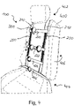
- FIG. 12 schematically shows a perspective view of a massage device 100 in one embodiment, which is attached to an assembly object 400, namely a seat of a vehicle.
- the massage system is designed analogously with the elements as before Figures 1 to 3 described and referred to.
- detachable connecting means 250 shown which are designed as a Velcro fastener.
- a strip of Velcro with loops extends along a path of the first and second vertical straps 210 and 212, respectively, with the horizontal straps 220, 222, 224 having a strip of Velcro with barbs at the connection points with the vertical straps 210, 212.
- the horizontal chord 220 can be attached to the two vertical chords 210, 212 at any desired position. This is indicated by a double arrow in the figure 4 illustrated.
- the assembly object has an upper area 402 , a lower area 404 and a rear area 406 .
- FIG. 12 illustrates how the massage device 100 is attached to the vehicle seat.
- loops are formed which are attached to the upper portion 402 and the lower portion 404.
- the vertical straps 210 and 212 as well as the horizontal straps 220-226 are tensioned, so that the massage means 300 for the carrier massage are detachably fastened to the straps.
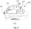
- the figure 5 shows schematically in a sectional and side view a massage means 300 in one embodiment, which is set up to vibrate.
- the massage means is equipped with a vibration device 320 arranged in an interior area of the massage means for vibration, wherein the vibration device 320 has a chargeable energy store 322 for supplying an electric vibration unit 324 and a switching means 326 for electrically connecting or disconnecting the vibration unit 324 to the energy store 322 .
- the vibration unit 324 is designed as an electric motor with an unbalance 330 that is attached to the shaft of the electric motor. With this arrangement, a vibration operation of the massage means 300 can be turned on and off.
- the rechargeable energy store which is also used as an accumulator can be understood to be recharged when the charge level of the memory has dropped.
- the massage means 300 also has a cavity in which support struts 328 are arranged to maintain the shape of the massage means when a force is applied.
Landscapes
- Health & Medical Sciences (AREA)
- Epidemiology (AREA)
- Pain & Pain Management (AREA)
- Physical Education & Sports Medicine (AREA)
- Rehabilitation Therapy (AREA)
- Life Sciences & Earth Sciences (AREA)
- Animal Behavior & Ethology (AREA)
- General Health & Medical Sciences (AREA)
- Public Health (AREA)
- Veterinary Medicine (AREA)
- Dermatology (AREA)
- Percussion Or Vibration Massage (AREA)
- Finger-Pressure Massage (AREA)
Priority Applications (1)
| Application Number | Priority Date | Filing Date | Title |
|---|---|---|---|
| EP21164172.5A EP4062891B1 (fr) | 2021-03-23 | 2021-03-23 | Dispositif de massage |
Applications Claiming Priority (1)
| Application Number | Priority Date | Filing Date | Title |
|---|---|---|---|
| EP21164172.5A EP4062891B1 (fr) | 2021-03-23 | 2021-03-23 | Dispositif de massage |
Publications (3)
| Publication Number | Publication Date |
|---|---|
| EP4062891A1 true EP4062891A1 (fr) | 2022-09-28 |
| EP4062891C0 EP4062891C0 (fr) | 2025-03-12 |
| EP4062891B1 EP4062891B1 (fr) | 2025-03-12 |
Family
ID=75173080
Family Applications (1)
| Application Number | Title | Priority Date | Filing Date |
|---|---|---|---|
| EP21164172.5A Active EP4062891B1 (fr) | 2021-03-23 | 2021-03-23 | Dispositif de massage |
Country Status (1)
| Country | Link |
|---|---|
| EP (1) | EP4062891B1 (fr) |
Citations (4)
| Publication number | Priority date | Publication date | Assignee | Title |
|---|---|---|---|---|
| GB2089217A (en) * | 1980-12-12 | 1982-06-23 | Soiron Ferdinand Von | Harness for eliminating tensions in the neck muscles |
| JPH1028625A (ja) * | 1996-07-17 | 1998-02-03 | Hisashi Kondo | 自動車シート用の背中マッサージ用具 |
| KR20140107887A (ko) * | 2013-02-28 | 2014-09-05 | 윤영근 | 전립선 온열 진동 마사지기 |
| US20150032038A1 (en) * | 2013-07-26 | 2015-01-29 | Ali Sied Atry | Self-Actuated Muscle Compression Device |
-
2021
- 2021-03-23 EP EP21164172.5A patent/EP4062891B1/fr active Active
Patent Citations (4)
| Publication number | Priority date | Publication date | Assignee | Title |
|---|---|---|---|---|
| GB2089217A (en) * | 1980-12-12 | 1982-06-23 | Soiron Ferdinand Von | Harness for eliminating tensions in the neck muscles |
| JPH1028625A (ja) * | 1996-07-17 | 1998-02-03 | Hisashi Kondo | 自動車シート用の背中マッサージ用具 |
| KR20140107887A (ko) * | 2013-02-28 | 2014-09-05 | 윤영근 | 전립선 온열 진동 마사지기 |
| US20150032038A1 (en) * | 2013-07-26 | 2015-01-29 | Ali Sied Atry | Self-Actuated Muscle Compression Device |
Also Published As
| Publication number | Publication date |
|---|---|
| EP4062891C0 (fr) | 2025-03-12 |
| EP4062891B1 (fr) | 2025-03-12 |
Similar Documents
| Publication | Publication Date | Title |
|---|---|---|
| EP3407842B1 (fr) | Orthèse de réclinaison à sangles de traction | |
| DE69000628T2 (de) | Orthese zur dreidimensionalen dynamischen rueckbildung einer skoliose. | |
| WO1985002537A1 (fr) | Prothese orthopedique pour l'articulation du genou | |
| EP2114325B1 (fr) | Dispositif pour soulager et soigner la colonne vertébrale cervicale | |
| EP1656972B1 (fr) | Appareil pour exercer les muscles abdominaux en position assise | |
| DE102013015288B4 (de) | Trainingsgerät | |
| EP4062891B1 (fr) | Dispositif de massage | |
| EP0078929B1 (fr) | Sommier à supports transversaux et éléments de liaison élastiques | |
| DE102020132128A1 (de) | Rückenorthese und Kit für eine Rückenorthese | |
| DE102013003746B4 (de) | Stuhl, Krafttrainingsgerät und Verwendung eines Stuhls als Krafttrainingsgerät | |
| DE102004009315A1 (de) | Vorrichtung zur Entlastung des Rückens | |
| WO2009068148A1 (fr) | Dispositif permettant de traiter une monture | |
| DE102004054085A1 (de) | Künstliches Bein vom Typ mit Sitzbeinunterstützung | |
| DE102014002375A1 (de) | Spannvorrichtung mit einem rahmen | |
| DE20020135U1 (de) | Trainingseinrichtung zur Erzielung einer Penisverlängerung und/oder Penisstimulierung | |
| EP4368154B1 (fr) | Orthèse dorsale | |
| DE3602784A1 (de) | Sprungbrett zum turnen | |
| EP3912694B1 (fr) | Dispositif de gymnastique | |
| DE102007012557B3 (de) | Bauchspanngurt | |
| DE19642765A1 (de) | Einstellbare Lendenwirbelstütze | |
| EP3576574A1 (fr) | Dispositif de siège destiné au support d'une position assise verticale | |
| DE102004008899B3 (de) | Trainingsgerät | |
| EP0387243B1 (fr) | Appareil pour le traitement conservatif de personnes souffrant de douleur à la région lombaire de la colonne vertebrale | |
| EP4477202A1 (fr) | Dispositif pour mobiliser le dos et ensemble | |
| DE2606729B2 (de) | Gerät zur therapeutischen Behandlung |
Legal Events
| Date | Code | Title | Description |
|---|---|---|---|
| PUAI | Public reference made under article 153(3) epc to a published international application that has entered the european phase |
Free format text: ORIGINAL CODE: 0009012 |
|
| STAA | Information on the status of an ep patent application or granted ep patent |
Free format text: STATUS: THE APPLICATION HAS BEEN PUBLISHED |
|
| AK | Designated contracting states |
Kind code of ref document: A1 Designated state(s): AL AT BE BG CH CY CZ DE DK EE ES FI FR GB GR HR HU IE IS IT LI LT LU LV MC MK MT NL NO PL PT RO RS SE SI SK SM TR |
|
| STAA | Information on the status of an ep patent application or granted ep patent |
Free format text: STATUS: REQUEST FOR EXAMINATION WAS MADE |
|
| 17P | Request for examination filed |
Effective date: 20230328 |
|
| RBV | Designated contracting states (corrected) |
Designated state(s): AL AT BE BG CH CY CZ DE DK EE ES FI FR GB GR HR HU IE IS IT LI LT LU LV MC MK MT NL NO PL PT RO RS SE SI SK SM TR |
|
| GRAP | Despatch of communication of intention to grant a patent |
Free format text: ORIGINAL CODE: EPIDOSNIGR1 |
|
| STAA | Information on the status of an ep patent application or granted ep patent |
Free format text: STATUS: GRANT OF PATENT IS INTENDED |
|
| RIC1 | Information provided on ipc code assigned before grant |
Ipc: A61H 11/00 20060101AFI20240925BHEP |
|
| INTG | Intention to grant announced |
Effective date: 20241004 |
|
| GRAS | Grant fee paid |
Free format text: ORIGINAL CODE: EPIDOSNIGR3 |
|
| GRAA | (expected) grant |
Free format text: ORIGINAL CODE: 0009210 |
|
| STAA | Information on the status of an ep patent application or granted ep patent |
Free format text: STATUS: THE PATENT HAS BEEN GRANTED |
|
| AK | Designated contracting states |
Kind code of ref document: B1 Designated state(s): AL AT BE BG CH CY CZ DE DK EE ES FI FR GB GR HR HU IE IS IT LI LT LU LV MC MK MT NL NO PL PT RO RS SE SI SK SM TR |
|
| REG | Reference to a national code |
Ref country code: GB Ref legal event code: FG4D Free format text: NOT ENGLISH |
|
| REG | Reference to a national code |
Ref country code: CH Ref legal event code: EP |
|
| REG | Reference to a national code |
Ref country code: DE Ref legal event code: R096 Ref document number: 502021006895 Country of ref document: DE |
|
| REG | Reference to a national code |
Ref country code: IE Ref legal event code: FG4D Free format text: LANGUAGE OF EP DOCUMENT: GERMAN |
|
| U01 | Request for unitary effect filed |
Effective date: 20250318 |
|
| U07 | Unitary effect registered |
Designated state(s): AT BE BG DE DK EE FI FR IT LT LU LV MT NL PT RO SE SI Effective date: 20250324 |
|
| PGFP | Annual fee paid to national office [announced via postgrant information from national office to epo] |
Ref country code: AT Payment date: 20250417 Year of fee payment: 5 |
|
| U20 | Renewal fee for the european patent with unitary effect paid |
Year of fee payment: 5 Effective date: 20250526 |
|
| PG25 | Lapsed in a contracting state [announced via postgrant information from national office to epo] |
Ref country code: RS Free format text: LAPSE BECAUSE OF FAILURE TO SUBMIT A TRANSLATION OF THE DESCRIPTION OR TO PAY THE FEE WITHIN THE PRESCRIBED TIME-LIMIT Effective date: 20250612 |
|
| PG25 | Lapsed in a contracting state [announced via postgrant information from national office to epo] |
Ref country code: ES Free format text: LAPSE BECAUSE OF FAILURE TO SUBMIT A TRANSLATION OF THE DESCRIPTION OR TO PAY THE FEE WITHIN THE PRESCRIBED TIME-LIMIT Effective date: 20250312 |
|
| PG25 | Lapsed in a contracting state [announced via postgrant information from national office to epo] |
Ref country code: NO Free format text: LAPSE BECAUSE OF FAILURE TO SUBMIT A TRANSLATION OF THE DESCRIPTION OR TO PAY THE FEE WITHIN THE PRESCRIBED TIME-LIMIT Effective date: 20250612 |
|
| PG25 | Lapsed in a contracting state [announced via postgrant information from national office to epo] |
Ref country code: HR Free format text: LAPSE BECAUSE OF FAILURE TO SUBMIT A TRANSLATION OF THE DESCRIPTION OR TO PAY THE FEE WITHIN THE PRESCRIBED TIME-LIMIT Effective date: 20250312 |
|
| PG25 | Lapsed in a contracting state [announced via postgrant information from national office to epo] |
Ref country code: GR Free format text: LAPSE BECAUSE OF FAILURE TO SUBMIT A TRANSLATION OF THE DESCRIPTION OR TO PAY THE FEE WITHIN THE PRESCRIBED TIME-LIMIT Effective date: 20250613 |
|
| PG25 | Lapsed in a contracting state [announced via postgrant information from national office to epo] |
Ref country code: SM Free format text: LAPSE BECAUSE OF FAILURE TO SUBMIT A TRANSLATION OF THE DESCRIPTION OR TO PAY THE FEE WITHIN THE PRESCRIBED TIME-LIMIT Effective date: 20250312 |
|
| PG25 | Lapsed in a contracting state [announced via postgrant information from national office to epo] |
Ref country code: PL Free format text: LAPSE BECAUSE OF FAILURE TO SUBMIT A TRANSLATION OF THE DESCRIPTION OR TO PAY THE FEE WITHIN THE PRESCRIBED TIME-LIMIT Effective date: 20250312 |
|
| PG25 | Lapsed in a contracting state [announced via postgrant information from national office to epo] |
Ref country code: CZ Free format text: LAPSE BECAUSE OF FAILURE TO SUBMIT A TRANSLATION OF THE DESCRIPTION OR TO PAY THE FEE WITHIN THE PRESCRIBED TIME-LIMIT Effective date: 20250312 |
|
| REG | Reference to a national code |
Ref country code: CH Ref legal event code: H13 Free format text: ST27 STATUS EVENT CODE: U-0-0-H10-H13 (AS PROVIDED BY THE NATIONAL OFFICE) Effective date: 20251023 |
|
| PG25 | Lapsed in a contracting state [announced via postgrant information from national office to epo] |
Ref country code: SK Free format text: LAPSE BECAUSE OF FAILURE TO SUBMIT A TRANSLATION OF THE DESCRIPTION OR TO PAY THE FEE WITHIN THE PRESCRIBED TIME-LIMIT Effective date: 20250312 |
|
| PG25 | Lapsed in a contracting state [announced via postgrant information from national office to epo] |
Ref country code: IS Free format text: LAPSE BECAUSE OF FAILURE TO SUBMIT A TRANSLATION OF THE DESCRIPTION OR TO PAY THE FEE WITHIN THE PRESCRIBED TIME-LIMIT Effective date: 20250712 |
|
| PG25 | Lapsed in a contracting state [announced via postgrant information from national office to epo] |
Ref country code: MC Free format text: LAPSE BECAUSE OF FAILURE TO SUBMIT A TRANSLATION OF THE DESCRIPTION OR TO PAY THE FEE WITHIN THE PRESCRIBED TIME-LIMIT Effective date: 20250312 |
|
| PLBE | No opposition filed within time limit |
Free format text: ORIGINAL CODE: 0009261 |
|
| STAA | Information on the status of an ep patent application or granted ep patent |
Free format text: STATUS: NO OPPOSITION FILED WITHIN TIME LIMIT |
|
| PG25 | Lapsed in a contracting state [announced via postgrant information from national office to epo] |
Ref country code: CH Free format text: LAPSE BECAUSE OF NON-PAYMENT OF DUE FEES Effective date: 20250331 |
|
| PG25 | Lapsed in a contracting state [announced via postgrant information from national office to epo] |
Ref country code: IE Free format text: LAPSE BECAUSE OF NON-PAYMENT OF DUE FEES Effective date: 20250323 |
|
| REG | Reference to a national code |
Ref country code: CH Ref legal event code: L10 Free format text: ST27 STATUS EVENT CODE: U-0-0-L10-L00 (AS PROVIDED BY THE NATIONAL OFFICE) Effective date: 20260121 |
|
| 26N | No opposition filed |
Effective date: 20251215 |
|
| GBPC | Gb: european patent ceased through non-payment of renewal fee |
Effective date: 20250612 |
|
| PG25 | Lapsed in a contracting state [announced via postgrant information from national office to epo] |
Ref country code: GB Free format text: LAPSE BECAUSE OF NON-PAYMENT OF DUE FEES Effective date: 20250612 |