EP4062996A1 - Filtre à air - Google Patents
Filtre à air Download PDFInfo
- Publication number
- EP4062996A1 EP4062996A1 EP20889064.0A EP20889064A EP4062996A1 EP 4062996 A1 EP4062996 A1 EP 4062996A1 EP 20889064 A EP20889064 A EP 20889064A EP 4062996 A1 EP4062996 A1 EP 4062996A1
- Authority
- EP
- European Patent Office
- Prior art keywords
- frame
- filter
- seal material
- air filter
- seal
- Prior art date
- Legal status (The legal status is an assumption and is not a legal conclusion. Google has not performed a legal analysis and makes no representation as to the accuracy of the status listed.)
- Granted
Links
Images





Classifications
-
- B—PERFORMING OPERATIONS; TRANSPORTING
- B01—PHYSICAL OR CHEMICAL PROCESSES OR APPARATUS IN GENERAL
- B01D—SEPARATION
- B01D46/00—Filters or filtering processes specially modified for separating dispersed particles from gases or vapours
- B01D46/52—Particle separators, e.g. dust precipitators, using filters embodying folded corrugated or wound sheet material
- B01D46/521—Particle separators, e.g. dust precipitators, using filters embodying folded corrugated or wound sheet material using folded, pleated material
-
- B—PERFORMING OPERATIONS; TRANSPORTING
- B01—PHYSICAL OR CHEMICAL PROCESSES OR APPARATUS IN GENERAL
- B01D—SEPARATION
- B01D46/00—Filters or filtering processes specially modified for separating dispersed particles from gases or vapours
- B01D46/52—Particle separators, e.g. dust precipitators, using filters embodying folded corrugated or wound sheet material
- B01D46/521—Particle separators, e.g. dust precipitators, using filters embodying folded corrugated or wound sheet material using folded, pleated material
- B01D46/523—Particle separators, e.g. dust precipitators, using filters embodying folded corrugated or wound sheet material using folded, pleated material with means for maintaining spacing between the pleats or folds
-
- B—PERFORMING OPERATIONS; TRANSPORTING
- B01—PHYSICAL OR CHEMICAL PROCESSES OR APPARATUS IN GENERAL
- B01D—SEPARATION
- B01D46/00—Filters or filtering processes specially modified for separating dispersed particles from gases or vapours
- B01D46/0002—Casings; Housings; Frame constructions
-
- B—PERFORMING OPERATIONS; TRANSPORTING
- B01—PHYSICAL OR CHEMICAL PROCESSES OR APPARATUS IN GENERAL
- B01D—SEPARATION
- B01D46/00—Filters or filtering processes specially modified for separating dispersed particles from gases or vapours
- B01D46/0084—Filters or filtering processes specially modified for separating dispersed particles from gases or vapours provided with safety means
- B01D46/0097—Special means for preventing bypass around the filter, i.e. in addition to usual seals
-
- F—MECHANICAL ENGINEERING; LIGHTING; HEATING; WEAPONS; BLASTING
- F16—ENGINEERING ELEMENTS AND UNITS; GENERAL MEASURES FOR PRODUCING AND MAINTAINING EFFECTIVE FUNCTIONING OF MACHINES OR INSTALLATIONS; THERMAL INSULATION IN GENERAL
- F16J—PISTONS; CYLINDERS; SEALINGS
- F16J15/00—Sealings
- F16J15/02—Sealings between relatively-stationary surfaces
- F16J15/14—Sealings between relatively-stationary surfaces by means of granular or plastic material, or fluid
-
- F—MECHANICAL ENGINEERING; LIGHTING; HEATING; WEAPONS; BLASTING
- F24—HEATING; RANGES; VENTILATING
- F24F—AIR-CONDITIONING; AIR-HUMIDIFICATION; VENTILATION; USE OF AIR CURRENTS FOR SCREENING
- F24F8/00—Treatment, e.g. purification, of air supplied to human living or working spaces otherwise than by heating, cooling, humidifying or drying
- F24F8/10—Treatment, e.g. purification, of air supplied to human living or working spaces otherwise than by heating, cooling, humidifying or drying by separation, e.g. by filtering
- F24F8/108—Treatment, e.g. purification, of air supplied to human living or working spaces otherwise than by heating, cooling, humidifying or drying by separation, e.g. by filtering using dry filter elements
-
- B—PERFORMING OPERATIONS; TRANSPORTING
- B01—PHYSICAL OR CHEMICAL PROCESSES OR APPARATUS IN GENERAL
- B01D—SEPARATION
- B01D2271/00—Sealings for filters specially adapted for separating dispersed particles from gases or vapours
- B01D2271/02—Gaskets, sealings
- B01D2271/022—Axial sealings
Definitions
- the present invention relates to an air filter.
- PTL 1 describes a filter with a lug.
- the filter with a lug prevents occurrence of air leak caused by the gap between the filter and the filter frame.
- the lug parts bonded to both ends of the filter are held and fixed between the filter frame and the prefilter frame. According to the configuration, no gap is formed between the filter and the filter frame, so as to prevent the occurrence of air leak.
- the filter with a lug of PTL 1 has a lug part in the direction along the folding lines of the filter. Therefore, the occurrence of gaps on the left and right side surfaces on the upstream side of the filter frame can be prevented, but it is difficult to prevent air leak occurring at the corner part, which is the seam part of the upper or lower frame and the left or right frame of the filter frame.
- the present invention has been made in consideration of the circumstances, and an object thereof is to provide an air filter that is capable of preventing air leak occurring at the corner part of the filter frame.
- the air filter according to the present invention includes: a pleated filter material folded into a zig-zag form at folding lines along a first direction to have peak parts and valley parts arising alternately in a second direction perpendicular to the first direction, trapping fine particles in a gaseous matter flowing in a gas flow direction perpendicular to the first direction and the second direction; a filter frame being a rectangular filter frame including one pair of first frame materials facing each other in the second direction having end parts in the first direction, and one pair of second frame materials facing each other in the first direction having end parts in the second direction, opening in the gas flow direction and housing the pleated filter material, each of the first frame materials and each of the second frame materials being combined to provide an overlap part where each of the end parts of each of the first frame materials and each of the end parts of each of the second frame materials overlap each other; and a buffer material disposed between at least each of the second frame materials of the filter frame and the pleated filter material, held with the overlap part.
- the air filter according to the present invention can prevent air leak occurring at the corner part of the filter frame.
- Fig. 1 is a perspective view of an air filter 1 according to the present embodiment.
- Fig. 2 is a partial cross sectional view of the air filter 1.
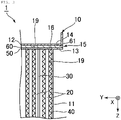
- Fig. 3 is a cross sectional view on the line III-III in Fig. 2 .
- the X direction in Figs. 1 to 11 is designated as a gas flow direction.
- the Z direction is designated as a vertically downward direction, and the inverse direction to the Z direction is designated as a vertically upward direction.
- the Y direction is designated as a horizontally leftward direction, and the inverse direction to the Y direction is designated as a horizontally rightward direction.
- the air filter 1 has a performance, for example, of a HEPA (high efficiency particulate air) filter.
- a HEPA filter is a filter that has a trapping efficiency of 99.97% or more at a rated air capacity to particles having a particle diameter of 0.3 ⁇ m, and an initial pressure loss of 245 Pa or less.
- the air filter 1 can be applied to various purposes of cleaning a gas at a high temperature.
- the air filter 1 is applied, for example, to cleaning of an exhaust gas discharged from an incinerator and cleaning of air in a drying furnace for drying components used in a semiconductor production process and a sterilization furnace for sterilizing medical devices.
- the air filter 1 is installed, for example, in midstream of a flow channel for a gas flow connected to the aforementioned furnace in incineration facilities, semiconductor production facilities, hospitals, research facilities, and the like.
- the air filter 1 includes a filter frame 10, a pleated filter material 20, a reinforcing plate 30, a separator 40, a seal material 50, and a buffer material 60.
- the filter frame 10 is a rectangular frame member that opens in the gas flow direction and houses the pleated filter material 20.
- the filter frame 10 is constituted by combining one pair of first frame materials 11 and one pair of second frame materials 12.
- the first frame materials 11 face each other in the horizontal direction (second direction) and have end parts 13 in the vertical direction (first direction).
- the second frame materials 12 face each other in the vertical direction and have end parts 14 in the horizontal direction.
- the filter frame 10 has four overlap parts 15 where each of the end parts 13 of each of the first frame materials 11 and each of the end parts 14 of each of the second frame materials 12 overlap each other, so as to combine the first frame material 11 and the second frame material 12.
- the first frame material 11 and the second frame material 12 are in contact directly or indirectly with each other in each of the overlap parts 15.
- the first frame material 11 and the second frame material 12 are connected and fixed with a connecting means, such as a bolt, in each of the overlap parts 15, so as to constitute the filter frame 10.
- the filter frame 10 is preferably formed of a material having heat resistance.
- the filter frame 10 is formed, for example, of a metal, such as stainless, a stainless steel (such as SUS304 and SUS430), aluminum, an aluminum alloy, a steel, and ceramics.
- the stainless may be plated with zinc or aluminum.
- the filter frame 10 may include a film formed through an alumite treatment, a chromate treatment, or the like.
- the pleated filter material 20 traps fine particles in a gaseous matter flowing in the gas flow direction.
- the pleated filter material 20 is formed by folding a filter material in a sheet form into a zig-zag form, and has peak parts and valley parts.
- the pleated filter material 20 has folding lines 21 along the vertical direction.
- the folding lines 21 form the peak parts and the valley parts appearing alternately in the horizontal direction.
- the pleated filter material 20 is disposed in the filter frame 10 in such a manner that the peak parts and the valley parts appear on the upstream side and the downstream side of the gas flow, respectively.
- the pleated filter material 20 is, for example, a fibrous material formed of glass fibers, silica fibers, or mixed fibers thereof.
- the pleated filter material 20 has, for example, such a form as a nonwoven fabric, paper, a cotton-like material, or a mat.
- the pleated filter material 20 may be formed of a glass nonwoven fabric, glass paper, glass wool, or the like formed of glass fibers.
- the pleated filter material 20 may contain a binder for adhering the fibers.
- the pleated filter material 20 may be held and supported between two sheets of breathable supports having heat resistance (such as metal meshes).
- the reinforcing plate 30 is a flat plate having an approximately rectangular shape.
- the reinforcing plate 30 is inserted between the peak parts adjacent to each other of the pleated filter material 20, i.e., inserted to the valley part thereof.
- the reinforcing plate 30 supports the positions in the vertical direction of the pleated filter material 20 and the other members. Specifically, the reinforcing plate 30 prevents the pleated filter material 20 and the separator 40 from being deformed (such as deviation and turnover) due to heat and from being deformed in the case where a physical force is applied thereto.
- Fig. 4 is a cross sectional view of the air filter 1 along the vertical direction for describing the reinforcing plate 30.
- the reinforcing plate 30 has one pair of edges 31 along the vertical direction and one pair of edges 32 along the gas flow direction. The lengths of the one pair of edges 31 along the vertical direction are approximately the same as the vertical length of the pleated filter material 20.
- the reinforcing plate 30 is inserted to at least a part of the valley part of the pleated filter material 20.
- the reinforcing plate 30 is disposed at a prescribed position of the air filter 1, and a necessary number of plies of the reinforcing plates 30 may be disposed.
- the reinforcing plate 30 has a thickness, for example, of 0.3 to 2.0 mm.
- the reinforcing plate 30 is formed, for example, of a metal.
- the reinforcing plate 30 that is formed of a metal supports the weight of the seal material 50 positioned upward, and prevents the seal material 50 from falling off.
- the thermal expansion coefficients (linear thermal expansion coefficients or linear expansion coefficients) of the reinforcing plate 30 and the filter frame 10 are preferably the same as each other. According to the configuration, for example, the breaking of the seal material 50 and the air filter 1 due to the effect of thermal expansion can be reduced.
- the air filter 1 In the case where the air filter 1 is used in a high temperature range as in a sterilization furnace or the like, the air filter 1 is exposed to a severe temperature change between stoppage and operation of the sterilization furnace. Under the repetition of the temperature change, the fibers of the seal material 50 are wasted to form a gap between the reinforcing plate 30 and the second frame material 12, which may cause leak.
- the air filter 1 has cutout parts 35 for the purpose of suppressing the occurrence of leak.
- the cutout parts 35 are formed on one pair of edges 32 along the gas flow direction, and each have a semicircular shape having an area increasing from both ends toward the center of each of the one pair of edges 32 along the gas flow direction.
- the one pair of edges 32 along the gas flow direction each have contact parts 36 and a non-contact part 37 with respect to the seal material 50.
- the contact parts 36 are formed on both the sides of the ends of the one pair of edges 32, and each are formed to have a width of 3 to 20 mm.
- the non-contact part 37 is the other part than the contact parts 36.
- the cutout parts 35 reduce the part where the reinforcing plate 30 comes into contact with the seal material 50.
- the reinforcing plate 30 expands in the vertical direction and the gas flow direction through thermal expansion. In a large expansion thereof in the vertical direction, the reinforcing plate 30 thrusts the seal material 50, and thereby the seal material 50 tends to crack.
- the elongation direction through thermal expansion of the reinforcing plate 30 can be diffused to reduce the elongation in the vertical direction. According to the mechanism, the thrust of the reinforcing plate 30 through thermal expansion onto the seal material 50 can be reduced to prevent the breaking of the seal material 50. Accordingly, even on repeated application of a high temperature, the reinforcing plate 30 suppresses the seal material 50 from being cracked, and prevents the leak from occurring.
- the separator 40 is a member retaining the gap (valley part) between the peak parts adjacent to each other of the pleated filter material 20.
- the separator 40 is formed, for example, of a metal, such as aluminum and a stainless steel.
- the separator 40 is preferably formed of aluminum or an aluminum alloy for weight reduction.
- the separator 40 has a thickness, for example, of 25 to 65 ⁇ m.
- the separator 40 is formed through corrugation where the material is folded into a wave shape.
- the separator 40 is inserted to each of the other valley parts than the valley part having the reinforcing plate 30 inserted thereto among the valley parts of the pleated filter material 20, in such a manner that the folding lines thereof are along the gas flow direction.
- the separator 40 has approximately the same vertical length as the vertical length of the pleated filter material 20.
- the seal material 50 (first and second seal materials) seals between at least a part of an inner surface 19 of the filter frame 10 (surface facing inward the air filter 1) and a part of the pleated filter material 20 facing that part.
- the seal material 50 seals between each of the second frame materials 12 and the pleated filter material 20.
- the pleated filter material 20 can come into surface contact with each of the first frame materials 11 through thrust of the separator 40, but comes into line contact with each of the second frame materials 12, failing to achieve surface contact.
- the seal material 50 is preferably provided between each of the second frame materials 12 and the pleated filter material 20. Due to the seal material 50 provided, the air filter 1 can exert a higher leak prevention effect than the case where only the buffer material 60 is provided between the filter frame 10 and the pleated filter material 20.
- the seal material 50 For suppressing the breaking of the seal material 50 due to the difference in thermal expansion amount from the filter frame 10 in the case where the air filter 1 is used in a high temperature range, it is considered to form the seal material 50 with a ceramic material that is regulated to have the same linear thermal expansion coefficient as the linear thermal expansion coefficient of the filter frame 10.
- the degree of freedom in selecting the material of the seal material 50 is restricted thereby.
- materials that have the same linear expansion coefficient in a certain temperature range have different linear thermal expansion coefficients in another temperature range, and there is a concern that the difference in thermal expansion amount cannot be suppressed consequently.
- the seal material formed of a ceramic material is generally obtained by coating a ceramic material in the form of paste on the filter material, followed by sintering.
- the present inventors have found that cracks of the seal material are formed in sintering the ceramic material, and dust emission from the ceramic material in use occurs due to the cracks. It has also been found that the dust emission from the seal material can be suppressed by using the following material as the seal material 50.
- the seal material 50 is formed of a ceramic material that has a ratio of the linear expansion coefficient (JIS R1618:2002) of the seal material 50 in a temperature range of 200 to 500°C of 10 to 200% with respect to the linear expansion coefficient (JIS Z2285:2003) of the filter frame 10 in that temperature range.
- the ceramic material include materials containing silica, alumina, and zirconia. It is preferred that the ceramic material does not contain crystalline silica (such as cristobalite) from the standpoint of preventing a carcinogenic material from being contained therein.
- the seal material 50 is formed, for example, by sintering a ceramic material in the form of paste or liquid.
- the seal material 50 of this type may have thereinside cracks occurring in sintering the ceramic material in some cases.
- the cracks have an effect of relaxing the stress inside the seal material 50 to suppress cracks newly occurring in use.
- the air filter 1 can be used.
- the ceramic material of the seal material 50 does not contain crystalline silica, contains amorphous silica and alumina, and is formed by sintering a ceramic material in the form of paste having a viscosity at room temperature (23°C) of 20,000 to 50,000 mPa ⁇ s.
- the crystalline silica is silica having a crystal structure of SiO 2 .
- the amorphous silica is silica having no crystal structure of SiO 2 .
- the ceramic material does not contain crystal silica, but contains amorphous silica or alumina, thereby facilitating the regulation of the thermal expansion coefficient of the seal material 50.
- the ceramic material has a viscosity at room temperature in the aforementioned range, and thereby is prevented from penetrating to the interior of the buffer material 60 before sintering. Accordingly, the function of the buffer material 60 described later allowing the seal material 50 to expand or contract after sintering can be favorably exhibited.
- the ceramic material having a viscosity in the aforementioned range at room temperature can be readily coated to a uniform thickness on the filter frame 10, and thereby the sintered seal material 50 can be suppressed from suffering unevenness in thickness and formation of pores.
- the components of the ceramic material in the form of paste except for water preferably contain amorphous silica and alumina in an amount of 50% by mass or more.
- the viscosity thereof at room temperature is preferably 25,000 to 45,000 mPa ⁇ s.
- the temperature range of 200 to 500°C is a temperature range of the atmosphere where the air filter 1 can be used.
- the temperature range is preferably 300 to 400°C. It suffices that the atmospheric temperature in use of the air filter 1 has the maximum temperature in the aforementioned temperature range, and for example, may be less than 200°C at the beginning of use.
- the ratio of the linear expansion coefficient of the seal material 50 with respect to the linear expansion coefficient of the filter frame 10 described above is calculated from the linear expansion coefficients of the filter frame 10 and the seal material 50 at the same temperature within the aforementioned temperature range. In the present embodiment, the ratio is 10 to 200%, and thereby the degree of freedom in selecting the combination of the filter frame 10 and the seal material 50 is enhanced.
- the ratio exceeds 200%, the thermal expansion of the seal material 50 along the filter frame 10 (along the horizontal direction, which is the longitudinal direction of the seal material 50) is restricted by each of the first frame materials 11, and thereby the compression stress is increased to cause a concern of breaking.
- the seal material 50 is pulled due to the too large thermal expansion amount of the filter frame 10 even though the buffer material 60 is provided, and thereby there is a concern that the cracks formed inside the seal material 50 proceed and appear on the surface of the seal material 50.
- the aforementioned ratio is preferably 50 to 150%.
- the linear expansion coefficient of the seal material 50 may be larger than the linear expansion coefficient of the filter frame 10, may be equal to the linear expansion coefficient of the filter frame 10, or may be smaller than the linear expansion coefficient of the filter frame 10.
- the linear expansion coefficient of the seal material 50 is larger than the linear expansion coefficient of the filter frame 10
- the thermal expansion of the seal material 50 in the longitudinal direction (horizontal direction) is restricted with an appropriate force of each of the first frame materials 11, which makes it difficult for the cracks of the seal material 50 to proceed. Therefore, the linear expansion coefficient of the seal material 50 is preferably larger than the linear expansion coefficient of the filter frame 10.
- the degree of freedom in selecting the combination of the filter frame 10 and the seal material 50 is enhanced, there are cases where the difference in thermal expansion amount between the filter frame 10 and the seal material 50 is increased depending on the selected combination thereof.
- the seal material 50 can expand or contract relative to the filter frame 10, and thereby the cracks inside the seal material 50 can be suppressed from proceeding. Consequently, the dust emission can be effectively suppressed.
- the linear expansion coefficient of the seal material 50 is also preferably 10% or more and less than 90% of the linear expansion coefficient of the filter frame 10 in a temperature range of 200 to 500°C.
- the case where the linear expansion coefficient of the seal material 50 is smaller than the linear expansion coefficient of the filter frame 10 is disadvantageous since the aforementioned effect of suppressing the progress of the cracks by appropriately restricting the thermal expansion of the seal material 50 in the longitudinal direction with the first frame material 11 is difficult to achieve.
- the buffer material 60 is disposed to intervene between the seal material 50 and the filter frame 10 as described above, and therefore the effect of suppressing the progress of the cracks can be obtained even though the thermal expansion of the seal material 50 is not restricted by the first frame material 11.
- the materials of the filter frame 10 for example, stainless has a larger linear expansion coefficient in a high temperature range than that in a low temperature range, and the thermal expansion amount of the filter frame 10 in use of the air filter 1 is larger than that in sintering. Accordingly, in the case where the seal material 50 is in contact with the filter frame 10, the seal material 50 is largely pulled by the filter frame 10, and the cracks of the seal material 50 readily proceed to cause dust emission.
- various ceramic materials having a smaller linear expansion coefficient than the stainless can be selected as the seal material 50 while selecting the stainless steel as the material of the filter frame 10, and thus even in this case, the progress of the cracks of the seal material 50 can be suppressed to suppress dust emission.
- the buffer material 60 is disposed between the second frame material 12 of the filter frame 10 and the seal material 50 (pleated filter material 20) .
- the buffer material 60 follows the expansion or contraction thereof, so as to retain the sealability between the pleated filter material 20 and the filter frame 10.
- the expansion or contraction of the filter frame 10 means the expansion or contraction thereof in the direction in parallel to the surface direction of the filter frame 10 facing the seal material 50.
- the buffer material 60 has ends 61 in the horizontal direction.
- the ends 61 are each extended to the overlap part 15 and held with the first frame material 11 and the second frame material 12.
- the buffer material 60 preferably has cushioning property and heat resistance, and is preferably formed, for example, of a fibrous material.
- the buffer material 60 formed of a fibrous material can readily expand and contact, and thus has a large effect of allowing the seal material 50 to expand or contact along the filter frame 10 (which may also be referred to as a buffer effect).
- the buffer material 60 formed of a fibrous material does not come into close contact with the filter frame 10, and thus can secure the slipperiness to the filter frame 10. Furthermore, in the case where the buffer material 60 in a compressed state is disposed between the seal material 50 and the filter frame 10, the sealability between the seal material 50 and the filter frame 10 can be obtained with the repulsive force of the fibrous material.
- the fibrous material may be formed, for example, of glass, ceramics, or minerals.
- the buffer material 60 formed of a fibrous material can contract along with the seal material 50 in sintering the seal material 50, and thereby an effect of suppressing the occurrence of cracks of the seal material 50 in sintering can also be obtained.
- the seal material 50 contracts, whereas the filter frame 10 expands. Accordingly, the buffer material 60 intervening between the seal material 50 and the filter frame 10 in sintering is effective therefor.
- the ceramics are, for example, a material containing silica, alumina, zirconia, and the like.
- a binder is contained in the buffer material 60
- the average fiber diameter of fibers constituting the fibrous material is, for example, 0.01 to 10 pm.
- the form of the buffer material 60 is, for example, a cotton-like form or a sponge form (porous form). Examples of the preferred buffer material 60 include glass wool and rock wool.
- no other member is disposed between the buffer material 60 and the seal material 50.
- the other member include a fibrous material in the form of sheet, such as filter paper and a nonwoven fabric. In the case where the member intervenes between the buffer material 60 and the seal material 50, there is a concern that the effect of suppressing the occurrence of cracks in sintering the seal material 50 is decreased.
- the air filter 1 particularly include a step of forming the seal material 50 and a step of disposing the buffer material 60.
- the step of forming the seal material 50 and the step of disposing the buffer material 60 may be performed, for example, in the manner shown in the items (1) and (2) below.
- the buffer material 60 is preferably disposed, for example, along the entire inner surface 19 of the second frame material 12.
- the seal material 50 preferably has such a size that does not protrude from the buffer material 60.
- the seal material 50 in the form of paste or liquid may be spontaneously dried, but is preferably sintered at a high temperature.
- the sintering is performed, for example, in a dry atmosphere at 100 to 200°C.
- the temperature is preferably increased to the sintering temperature at a temperature increasing rate of 3 to 16°C/min for suppressing the occurrence of cracks of the seal material 50.
- the seal material 50 in the form of paste does not contain crystalline silica, contains amorphous silica and alumina, and has a viscosity at room temperature (23°C) of 20,000 to 50,000 mPa ⁇ s, as described above.
- the thickness of the seal material 50 is preferably 3 to 20 mm.
- the thickness of the seal material 50 is preferably 5 to 15 mm.
- the thickness of the seal material 50 means the thickness thereof in the dry state (state after sintering). It has been found that the seal material 50 more readily causes cracks in sintering with a smaller thickness thereof. While a large internal stress occurs in the seal material 50 due to the contraction of the seal material 50 at the time when water escapes from the seal material 50 in sintering, it is considered that the thin seal material 50 cannot withstand the large internal stress. On the other hand, a too large thickness of the seal material 50 fails to achieve weight reduction of the air filter 1.
- the thickness of the buffer material 60 is preferably 1 to 15 mm.
- the thickness of the buffer material 60 is particularly preferably 3 to 10 mm.
- the seal material 50 moves downward due to the own weight thereof to compress the buffer material 60 against the filter frame 10. Accordingly, a gap occurs on the opposite side, i.e., between the buffer material 60 facing the second frame material 12 on the upper side and the second frame material 12 on the upper side, which causes a concern that leak occurs. This problem becomes conspicuous particularly in the case where the thickness of the seal material 50 is large.
- the ratio of the thickness of the seal material 50 with respect to the thickness of the buffer material 60 is preferably 1 or more, and more preferably 1.2 or more.
- the aforementioned ratio is preferably 5 or less, and more preferably 3 or less.
- the thickness of the buffer material 60 means the average value of the thicknesses measured at plural (three or more) positions along the longitudinal direction (horizontal direction) of the buffer material 60 disposed between the seal material 50 and the filter frame 10.
- the thickness of the buffer material 60 can be measured, for example, with a vernier caliper.
- the filter frame 10 has a corner part 16 formed in the overlap part 15.
- the corner part 16 is formed on the side of the inner surface 19 of the filter frame 10, and is a part where the first frame material 11 and the second frame material 12 perpendicularly cross each other.
- the pleated filter material 20 is disposed gas tightly on the filter frame 10 via the buffer material 60 and the seal material 50.
- more than a little gap is formed between the corner part 16 and the buffer material 60 or the seal material 50, resulting in a concern that air leak occurs at the corner part 16.
- the filter frame 10 is formed of a metal, in particular, there is a concern that air leak occurs.
- the buffer material 60 is extended to the overlap part 15 and held with the first frame material 11 and the second frame material 12. According to the configuration, the buffer material 60 can favorably prevent the formation of the gap and can suppress the air leak. As a result, the air filter 1 can suppress the decrease in trapping efficiency occurring locally at the corner part 16.
- the buffer material 60 may be provided between the pleated filter material 20 and the first frame material 11, and may be provided between the pleated filter material 20 and both the first frame material 11 and the second frame material 12.
- the buffer material 60 may also have the function of the seal material 50.
- the seal material 50 may be constituted, for example, by a geopolymer, glass wool, or urethane, other than the ceramic material.
- the air filter 1 may include a filling material used in the overlap part 15 for further reducing the air leak.
- Fig. 5 is a cross sectional view showing an air filter 1a as a modified example corresponding to Fig. 3 . The configurations and the parts thereof corresponding to the air filter 1 are attached with the same symbols, and redundant descriptions therefor are omitted.
- the air filter 1a includes a filling material 70 that is further disposed in the overlap part 15 in addition to the buffer material 60. Specifically, the filling material 70 is held between the first frame material 11 and the second frame material 12 in the overlap part 15, and fills the gap in the overlap part 15.
- the filling material 70 is formed of a material capable of filling the gap in the overlap part 15, and is formed, for example, of the similar filter paper to the pleated filter material 20, a sintered article of long fibers, or a foamed article.
- the filling material 70 may be disposed between the buffer material 60 and the second frame material 12. In alternative, the filling material 70 may be disposed between the separator 40 and the first frame material 11.
- the filling material 70 is preferably disposed on the buffer material 60 in the overlap part 15 on the side of the first frame material 11 and the bolt for clamping the first frame material 11. In clamping with the bolt, there is a concern that the fibers of the buffer material 60 are entangled on the bolt, inhibiting the clamping and releasing of the bolt.
- the filling material 70 is disposed between the bolt and the buffer material 60, thereby preventing the buffer material 60 from being entangled on the bolt in inserting the bolt.
- the filling material 70 presses the fibers of the buffer material 60 for preventing the fibers of the buffer material 60 entangled on the bolt from being taken out along with the bolt in releasing the bolt.
- the air filter 1a includes both the filling material 70 and the buffer material 60 existing in the overlap part 15, and thereby the gap in the overlap part 15 is filled more effectively to prevent the air leak than the air filter 1.
- FIG. 6 is a cross sectional view showing an air filter 1b as another modified example corresponding to Fig. 3 .
- An air filter 1b includes a buffer material 60b having an end part 61b that is folded along the shape of the inner surface 19 of the filter frame 10 for further reducing the air leak.
- the buffer material 60b has an angle part 62 formed by folding the end part 61b to the downward direction or the upward direction along the gas flow direction.
- the buffer material 60b is collapsed due to the cushioning property thereof in fabricating to form the overlap part 15 with the first frame material 11 and the second frame material 12, so that the a part of the angle part 62 is held in the overlap part 15.
- the buffer material 60b securely covers the corner part 16 and the gap between the pleated filter material 20 and the seal material 50, and thereby the air leak occurring from the corner part 16 can be further suppressed.
- the filling material 70 is disposed in the overlap part 15.
- the shape of the cutout part 35 is not particularly limited.
- plural cutout parts 35 may be provided on one pair of edges 32 along the gas flow direction, and the cutout part 35 may have a rectangular shape or a polygonal shape, but not a semicircular shape.
- Fig. 7 is a cross sectional view of an air filter 1c along the vertical direction for describing another reinforcing plate 30c corresponding to Fig. 4 .
- the configurations and the parts thereof corresponding to the air filter 1 are attached with the same symbols, and redundant descriptions therefor are omitted.
- the reinforcing plate 30c has cutout parts 35c each having an approximately rectangular shape, so as to form contact parts 36c and a non-contact part 37c on each of one pair of edges 32 along the gas flow direction.
- the expansion of the reinforcing plate 30c at the cutout part 35c occurs in the directions perpendicular to the edges constituting the periphery of the cutout part 35c, i.e., in the vertical direction and the gas flow direction.
- the contact parts 36c can be reduced, and the thrust of the reinforcing plate 30c onto the seal material 50 can be reduced similarly to the reinforcing plate 30. Consequently, the breaking of the seal material 50 in the air filter 1c can be prevented.
- the linear part constituting the periphery of the cutout part thermally expands in the direction perpendicular to the linear direction thereof, and the curved part thermally expands in the centrifugal directions.
- the reinforcing plate thermally expands in the centrifugal directions from the cutout part (i.e., in the directions not along the vertical direction), and thereby the force pressing the seal material 50 in the vertical direction is dispersed and reduced.
- the reinforcing plate can further prevent the breaking of the seal material 50 in the case where the cutout part 35 having a semicircular shape having no part perpendicular to the vertical direction is provided.
- the pleated filter material 20 comes into surface contact at end parts in the horizontal direction with each of the first frame materials 11 through thrust of the separator 40 as described above, and a presser plate may be provided for further sealing the contact surface.
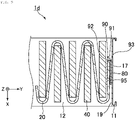
- Fig. 8 is an illustrative view showing an air filter 1d having a presser plate 90.
- Fig. 9 is a cross sectional view on the line IX-IX in Fig. 8 .
- the first frame material 11 and the second frame material 12 are partially omitted from the illustration.
- the configurations and the parts thereof corresponding to the air filter 1 are attached with the same symbols, and redundant descriptions therefor are omitted.
- the air filter 1d further includes, as compared with the air filter 1, a right and left side seal material 80 and a presser plate 90.
- the right and left side seal material 80 (third seal material) seals between a part on the inner surface 19 of each of the first frame material 11 and an end part 17 in the horizontal direction of the pleated filter material 20 facing the part of the inner surface 19.
- the right and left side seal material 80 is formed of the same material as the seal material 50 or glass fibers.
- the presser plate 90 compresses and holds the end part 17 of the pleated filter material 20 and the right and left side seal material 80, which are closely in contact with the first frame material 11 thereby.
- the presser plate 90 is formed of a thin plate of a metal, such as stainless, that is folded to have an L-shape viewed in the vertical direction.
- the presser plate 90 includes a rise part 91 and a press part 95.
- the rise part 91 is disposed perpendicularly to the inner surface 19 of the first frame material 11.
- the rise part 91 is disposed perpendicularly to the gas flow direction to cover the boundary between the right and left side seal material 80 and the end part 17 viewed from the upstream side.
- the rise part 91 has approximately the same vertical length as the vertical length of the pleated filter material 20.
- the rise part 91 has a smaller horizontal length than the thickness (horizontal length) of the right and left side seal material 80 and the pleated filter material 20 under no load.
- the press part 95 is a part that is formed by folding from an end part 92, which is one of end parts in the horizontal direction of the rise part 91 that is located separately from the first frame material 11, to the downstream side approximately perpendicularly to the rise part 91.
- the press part 95 is inserted between the end part 17 and the separator 40 disposed in the valley part formed by the pleated filter material 20 including the end part 17.
- an end part 93 which is one of end parts in the horizontal direction of the rise part 91 that is located on the side of the first frame material 11, is fixed to the inner surface 19 of the first frame material 11.
- the presser plate 90 is fixed with various fixing means, such as welding and a screw.
- the presser plate 90 is preferably fixed through welding, for reducing the gap between the inner surface 19 and the presser plate 90.
- the presser plate 90 forms a housing space with the inner surface 19 of the first frame material 11, the rise part 91, and the press part 95.
- the horizontal length of the rise part 91 is set to a smaller value than the thickness of the right and left side seal material 80 and the pleated filter material 20, as described above.
- the presser plate 90 houses in the housing space thereof the pleated filter material 20 and the right and left side seal material 80 under compression with the press part 95 in the direction toward the inner surface 19.
- the right and left side seal material 80 and the pleated filter material 20 are pressed onto the inner surface 19 of the first frame material 11.
- sealability can be obtained in the gaps among the inner surface 19 of the first frame material 11, the right and left side seal material 80, and the pleated filter material 20, and dust can be suppressed from entering into the gap between the first frame material 11 and the right and left side seal material 80.
- the voids in the fibers of the right and left side seal material 80 formed of a fibrous material can be reduced by compressing the right and left side seal material 80, thereby increasing the sealability.
- the presser plate 90 is disposed in such a manner that the rise part 91 covers the boundary between the right and left side seal material 80 and the end part 17 viewed from the downstream side.
- the vertical length of the presser plate 90 may be shorter than the vertical length of the pleated filter material 20, and the presser plate 90 may be disposed by dividing along the vertical direction.
- the shape of the presser plate 90 is not limited to the above, and another shape may be used as far as sealability can be imparted to gaps among the inner surface 19 of the first frame material 11, the right and left side seal material 80, and the pleated filter material 20.
- Fig. 10 is a cross sectional view of an air filter 1e having another presser plate 90e corresponding to Fig. 9 .
- the configurations and the parts thereof corresponding to the air filter 1 are attached with the same symbols, and redundant descriptions therefor are omitted.
- the presser plate 90e includes a rise part 91e and a press part 95e.
- the rise part 91e is disposed perpendicularly to the inner surface 19 of the first frame material 11.
- the rise part 91e is disposed perpendicularly to the gas flow direction to cover the boundary between the right and left side seal material 80 and the end part 17 viewed from the upstream side, along with the press part 95e.
- the rise part 91e has approximately the same vertical length as the vertical length of the pleated filter material 20.
- the press part 95e is a part that is formed by folding from an end part 93e, which is one of end parts in the horizontal direction of the rise part 91e that is located on the side of the first frame material 11, to the downstream side.
- the press part 95e is folded in such a manner that it gradually opens in the direction away from the inner surface 19 of the first frame material 11. According to the configuration, the press part 95e functions as a leaf spring pressing the end part 17 and the right and left side seal material 80 onto the inner surface 19.
- the presser plate 90e forms a housing space with the inner surface 19 of the first frame material 11 and the press part 95e.
- the horizontal length of the housing space (distance from the inner surface 19) is gradually increased along the gas flow direction.
- the presser plate 90e has a larger force pressing the right and left side seal material 80 and the pleated filter material 20 onto the inner surface 19 than the presser plate 90 due to the spring property thereof, and thus can further enhance the sealability.
- Fig. 11 is a cross sectional view of an air filter 1f having another right and left side seal material 80f corresponding to Fig. 9 .
- the right and left side seal material 80f is disposed between the first frame material 11 and the pleated filter material 20, and is also disposed between the pleated filter material 20 and the press part 95f by folding at the tip of the end part 17. According to the configuration, the thickness of the right and left side seal material 80 housed in the housing space is increased to enhance the compression rate of the right and left side seal material 80. Accordingly, the presser plate 90f can have a larger force pressing the right and left side seal material 80 and the pleated filter material 20 down onto the inner surface 19, and thus can further enhance the sealability.
Landscapes
- Chemical & Material Sciences (AREA)
- Chemical Kinetics & Catalysis (AREA)
- Engineering & Computer Science (AREA)
- General Engineering & Computer Science (AREA)
- Mechanical Engineering (AREA)
- Combustion & Propulsion (AREA)
- Filtering Of Dispersed Particles In Gases (AREA)
Applications Claiming Priority (6)
| Application Number | Priority Date | Filing Date | Title |
|---|---|---|---|
| JP2019210815 | 2019-11-21 | ||
| JP2019232222A JP7418911B2 (ja) | 2019-12-24 | 2019-12-24 | エアフィルタ |
| JP2020002170A JP7287907B2 (ja) | 2020-01-09 | 2020-01-09 | エアフィルタ |
| JP2020048208A JP7530190B2 (ja) | 2020-03-18 | 2020-03-18 | エアフィルタ |
| JP2020056458A JP7537896B2 (ja) | 2019-11-21 | 2020-03-26 | エアフィルタ |
| PCT/JP2020/043506 WO2021100873A1 (fr) | 2019-11-21 | 2020-11-20 | Filtre à air |
Publications (3)
| Publication Number | Publication Date |
|---|---|
| EP4062996A1 true EP4062996A1 (fr) | 2022-09-28 |
| EP4062996A4 EP4062996A4 (fr) | 2023-09-13 |
| EP4062996B1 EP4062996B1 (fr) | 2025-07-02 |
Family
ID=75980151
Family Applications (1)
| Application Number | Title | Priority Date | Filing Date |
|---|---|---|---|
| EP20889064.0A Active EP4062996B1 (fr) | 2019-11-21 | 2020-11-20 | Filtre à air |
Country Status (5)
| Country | Link |
|---|---|
| US (1) | US12544703B2 (fr) |
| EP (1) | EP4062996B1 (fr) |
| CN (1) | CN114746162B (fr) |
| ES (1) | ES3035687T3 (fr) |
| WO (1) | WO2021100873A1 (fr) |
Families Citing this family (2)
| Publication number | Priority date | Publication date | Assignee | Title |
|---|---|---|---|---|
| CN116440615B (zh) * | 2023-05-27 | 2025-09-16 | 杭州科百特过滤器材有限公司 | 一种高温空气过滤器 |
| TWI904631B (zh) * | 2024-04-10 | 2025-11-11 | 鈺祥企業股份有限公司 | 具有夾合結構之濾網框體 |
Family Cites Families (35)
| Publication number | Priority date | Publication date | Assignee | Title |
|---|---|---|---|---|
| GB513976A (en) * | 1938-08-09 | 1939-10-26 | Glenn L Martin Co | Methods of forming a sealed connection between two structural members |
| US3659719A (en) * | 1970-12-07 | 1972-05-02 | American Air Filter Co | Filter frame construction |
| US4199387A (en) * | 1977-12-02 | 1980-04-22 | Cambridge Filter Corporation | Air filter fabrication method |
| US4584005A (en) * | 1984-06-27 | 1986-04-22 | Flanders Filters, Inc. | High efficiency particulate air filter and method of fabricating same |
| US4885015A (en) | 1988-10-03 | 1989-12-05 | Cambridge Filter Corporation | HEPA air filter for high temperature environments and method of fabrication |
| US5639287A (en) * | 1994-05-16 | 1997-06-17 | Minnesota Mining And Manufacturing Company | Filter system for filtering fluids |
| JP3460032B2 (ja) * | 1995-01-09 | 2003-10-27 | ニッタ株式会社 | エアーフィルタ |
| JP2976065B2 (ja) | 1996-03-29 | 1999-11-10 | 金井 宏彰 | フィルタ |
| JP2000317237A (ja) * | 1999-05-07 | 2000-11-21 | Tokyo Roki Co Ltd | フィルタエレメント |
| US6406509B1 (en) * | 1999-07-01 | 2002-06-18 | 3M Innovative Properties Company | Extruded profile filter framing |
| US6521011B1 (en) * | 1999-07-15 | 2003-02-18 | 3M Innovative Properties Company | Self-supporting pleated filter and method of making same |
| US6319300B1 (en) * | 2000-07-12 | 2001-11-20 | Liou-Win Chen | Filter assembly of an air filter |
| JP2002166113A (ja) | 2000-11-29 | 2002-06-11 | Akamatsu Denki Seisakusho:Kk | 集塵用フィルター |
| US7001449B2 (en) * | 2001-02-05 | 2006-02-21 | N.V. Bekaert S.A. | Diesel exhaust filter system with electrical regeneration |
| DE10131422C2 (de) * | 2001-06-29 | 2003-05-08 | Sandler Helmut Helsa Werke | Filterelement mit einem plissierten Filterpack |
| US6740136B2 (en) * | 2001-10-12 | 2004-05-25 | 3M Innovative Properties Company | Interconnected filter frame and filter framing method |
| JP2003120815A (ja) * | 2001-10-18 | 2003-04-23 | Japan Gore Tex Inc | 矩形シール材 |
| US7294162B2 (en) * | 2003-11-04 | 2007-11-13 | Donaldson Company, Inc. | Exhaust filter |
| DE102004054246A1 (de) * | 2004-09-27 | 2006-04-06 | Carl Freudenberg Kg | Anordnung für ein plattenförmiges Filterelement in einem Gasfiltergehäuse |
| JP4696564B2 (ja) * | 2005-01-18 | 2011-06-08 | パナソニック株式会社 | フィルタ収納装置 |
| US7497888B2 (en) * | 2005-09-02 | 2009-03-03 | Ashwood Matthew P | Flexible size adjustable filter element |
| US7537632B2 (en) * | 2006-06-22 | 2009-05-26 | Clarcor Air Filtration Products, Inc. | Panel filter with frame |
| US7959699B2 (en) * | 2007-09-20 | 2011-06-14 | Lennox Industries Inc. | Collapsible filter with folding arms |
| JP4972020B2 (ja) | 2008-03-18 | 2012-07-11 | 日本バイリーン株式会社 | フィルタエレメント製造用櫛状部材、及びフィルタエレメント製造用櫛状部材を用いたフィルタエレメントの製造方法 |
| JP5049851B2 (ja) * | 2008-04-03 | 2012-10-17 | 日本無機株式会社 | 耐熱フィルタ |
| US20090301044A1 (en) * | 2008-06-09 | 2009-12-10 | Superior Fibers Llc | air filter frame |
| DE202008015078U1 (de) * | 2008-11-13 | 2010-04-08 | Mann+Hummel Gmbh | Luftfiltereinsatz |
| US8163054B1 (en) * | 2009-01-23 | 2012-04-24 | Glasfloss Industries, LP | Air filter with internal frame support |
| JP5651425B2 (ja) | 2010-10-22 | 2015-01-14 | 日本無機株式会社 | 耐熱フィルタおよび耐熱フィルタの製造方法 |
| JP2012240042A (ja) * | 2011-05-18 | 2012-12-10 | Nippon Air Filter Kk | 高温用エアフィルタ |
| US8685129B2 (en) * | 2011-06-14 | 2014-04-01 | 3M Innovative Properties Company | Framed air filter and method of making |
| JP5961450B2 (ja) * | 2012-05-29 | 2016-08-02 | 日本無機株式会社 | フィルタ及びフィルタの製造方法 |
| JP6275957B2 (ja) * | 2013-05-09 | 2018-02-07 | 日本無機株式会社 | ろ過装置、固定部材付き取付枠、及びろ過体 |
| US20150267927A1 (en) * | 2014-03-21 | 2015-09-24 | 3M Innovative Properties Company | Collapsible air filter assembly |
| JP6148275B2 (ja) | 2015-03-27 | 2017-06-14 | 進和テック株式会社 | 高温用エアフィルタとその製造方法 |
-
2020
- 2020-11-20 ES ES20889064T patent/ES3035687T3/es active Active
- 2020-11-20 EP EP20889064.0A patent/EP4062996B1/fr active Active
- 2020-11-20 CN CN202080080310.2A patent/CN114746162B/zh active Active
- 2020-11-20 US US17/777,912 patent/US12544703B2/en active Active
- 2020-11-20 WO PCT/JP2020/043506 patent/WO2021100873A1/fr not_active Ceased
Also Published As
| Publication number | Publication date |
|---|---|
| US20220401871A1 (en) | 2022-12-22 |
| CN114746162A (zh) | 2022-07-12 |
| EP4062996B1 (fr) | 2025-07-02 |
| EP4062996A4 (fr) | 2023-09-13 |
| WO2021100873A1 (fr) | 2021-05-27 |
| ES3035687T3 (en) | 2025-09-08 |
| CN114746162B (zh) | 2023-09-08 |
| US12544703B2 (en) | 2026-02-10 |
Similar Documents
| Publication | Publication Date | Title |
|---|---|---|
| US12544703B2 (en) | Air filter | |
| CN102575542B (zh) | 用于排气处理装置的安装垫 | |
| CN102686843B (zh) | 多层基底支承体和排气处理装置 | |
| KR100844250B1 (ko) | 소성로 및 이것을 이용한 다공질 세라믹 부재의 제조 방법 | |
| TWI765858B (zh) | 用於高溫應用之高效空氣過濾器組件、製造其之方法及其用途 | |
| JP7537896B2 (ja) | エアフィルタ | |
| EP3296008A1 (fr) | Filtre pour températures élevées | |
| JP2001082681A (ja) | 断熱材および複合断熱材 | |
| JP4283705B2 (ja) | 高温用エアフィルタ | |
| EP2583343B1 (fr) | Répartiteur de force pour un empilement de piles à combustible ou de cellules électrolytiques | |
| JP4715046B2 (ja) | ガスフィルタ装置 | |
| JPH0587756B2 (fr) | ||
| CN116440615B (zh) | 一种高温空气过滤器 | |
| CN219922419U (zh) | 一种空气过滤器 | |
| KR20250142344A (ko) | 에어 필터 | |
| JP3471711B2 (ja) | フィルタエレメントの保持構造 | |
| WO2023085438A1 (fr) | Structure d'isolation thermique, structure de four industriel et procédé de montage de structure d'isolation thermique | |
| JPS6335784Y2 (fr) | ||
| JP3370583B2 (ja) | 触媒コンバータ用シール材の製造方法 | |
| CN2830857Y (zh) | 防尘型非金属膨胀节 | |
| JPH0230715Y2 (fr) | ||
| JPH0326314A (ja) | ディーゼル機関排気微粒子除去装置 | |
| JP3229127B2 (ja) | セラミックス管のシール構造 | |
| JP2001219017A (ja) | フィルタ素子及びフィルタ素子アッセンブリ | |
| JP2005021760A (ja) | 高温用エアフィルタ |
Legal Events
| Date | Code | Title | Description |
|---|---|---|---|
| STAA | Information on the status of an ep patent application or granted ep patent |
Free format text: STATUS: THE INTERNATIONAL PUBLICATION HAS BEEN MADE |
|
| PUAI | Public reference made under article 153(3) epc to a published international application that has entered the european phase |
Free format text: ORIGINAL CODE: 0009012 |
|
| STAA | Information on the status of an ep patent application or granted ep patent |
Free format text: STATUS: REQUEST FOR EXAMINATION WAS MADE |
|
| 17P | Request for examination filed |
Effective date: 20220601 |
|
| AK | Designated contracting states |
Kind code of ref document: A1 Designated state(s): AL AT BE BG CH CY CZ DE DK EE ES FI FR GB GR HR HU IE IS IT LI LT LU LV MC MK MT NL NO PL PT RO RS SE SI SK SM TR |
|
| DAV | Request for validation of the european patent (deleted) | ||
| DAX | Request for extension of the european patent (deleted) | ||
| A4 | Supplementary search report drawn up and despatched |
Effective date: 20230816 |
|
| RIC1 | Information provided on ipc code assigned before grant |
Ipc: F16J 15/14 20060101ALI20230809BHEP Ipc: F16J 15/10 20060101ALI20230809BHEP Ipc: F24F 7/003 20210101ALI20230809BHEP Ipc: B01D 46/52 20060101AFI20230809BHEP |
|
| STAA | Information on the status of an ep patent application or granted ep patent |
Free format text: STATUS: EXAMINATION IS IN PROGRESS |
|
| 17Q | First examination report despatched |
Effective date: 20240508 |
|
| GRAP | Despatch of communication of intention to grant a patent |
Free format text: ORIGINAL CODE: EPIDOSNIGR1 |
|
| STAA | Information on the status of an ep patent application or granted ep patent |
Free format text: STATUS: GRANT OF PATENT IS INTENDED |
|
| INTG | Intention to grant announced |
Effective date: 20250130 |
|
| RIN1 | Information on inventor provided before grant (corrected) |
Inventor name: YAMAGUCHI, TAKEKI Inventor name: HAYASHI, SHIRO Inventor name: SEKI, KAZUYA |
|
| GRAS | Grant fee paid |
Free format text: ORIGINAL CODE: EPIDOSNIGR3 |
|
| GRAA | (expected) grant |
Free format text: ORIGINAL CODE: 0009210 |
|
| STAA | Information on the status of an ep patent application or granted ep patent |
Free format text: STATUS: THE PATENT HAS BEEN GRANTED |
|
| AK | Designated contracting states |
Kind code of ref document: B1 Designated state(s): AL AT BE BG CH CY CZ DE DK EE ES FI FR GB GR HR HU IE IS IT LI LT LU LV MC MK MT NL NO PL PT RO RS SE SI SK SM TR |
|
| REG | Reference to a national code |
Ref country code: GB Ref legal event code: FG4D |
|
| REG | Reference to a national code |
Ref country code: CH Ref legal event code: EP |
|
| REG | Reference to a national code |
Ref country code: DE Ref legal event code: R096 Ref document number: 602020054000 Country of ref document: DE |
|
| REG | Reference to a national code |
Ref country code: IE Ref legal event code: FG4D |
|
| REG | Reference to a national code |
Ref country code: ES Ref legal event code: FG2A Ref document number: 3035687 Country of ref document: ES Kind code of ref document: T3 Effective date: 20250908 |
|
| REG | Reference to a national code |
Ref country code: NL Ref legal event code: MP Effective date: 20250702 |
|
| PG25 | Lapsed in a contracting state [announced via postgrant information from national office to epo] |
Ref country code: PT Free format text: LAPSE BECAUSE OF FAILURE TO SUBMIT A TRANSLATION OF THE DESCRIPTION OR TO PAY THE FEE WITHIN THE PRESCRIBED TIME-LIMIT Effective date: 20251103 |
|
| PG25 | Lapsed in a contracting state [announced via postgrant information from national office to epo] |
Ref country code: NL Free format text: LAPSE BECAUSE OF FAILURE TO SUBMIT A TRANSLATION OF THE DESCRIPTION OR TO PAY THE FEE WITHIN THE PRESCRIBED TIME-LIMIT Effective date: 20250702 |
|
| REG | Reference to a national code |
Ref country code: AT Ref legal event code: MK05 Ref document number: 1808649 Country of ref document: AT Kind code of ref document: T Effective date: 20250702 |
|
| PG25 | Lapsed in a contracting state [announced via postgrant information from national office to epo] |
Ref country code: IS Free format text: LAPSE BECAUSE OF FAILURE TO SUBMIT A TRANSLATION OF THE DESCRIPTION OR TO PAY THE FEE WITHIN THE PRESCRIBED TIME-LIMIT Effective date: 20251102 |
|
| PGFP | Annual fee paid to national office [announced via postgrant information from national office to epo] |
Ref country code: DE Payment date: 20251118 Year of fee payment: 6 |
|
| PG25 | Lapsed in a contracting state [announced via postgrant information from national office to epo] |
Ref country code: NO Free format text: LAPSE BECAUSE OF FAILURE TO SUBMIT A TRANSLATION OF THE DESCRIPTION OR TO PAY THE FEE WITHIN THE PRESCRIBED TIME-LIMIT Effective date: 20251002 |
|
| REG | Reference to a national code |
Ref country code: LT Ref legal event code: MG9D |
|
| PG25 | Lapsed in a contracting state [announced via postgrant information from national office to epo] |
Ref country code: AT Free format text: LAPSE BECAUSE OF FAILURE TO SUBMIT A TRANSLATION OF THE DESCRIPTION OR TO PAY THE FEE WITHIN THE PRESCRIBED TIME-LIMIT Effective date: 20250702 |
|
| PG25 | Lapsed in a contracting state [announced via postgrant information from national office to epo] |
Ref country code: FI Free format text: LAPSE BECAUSE OF FAILURE TO SUBMIT A TRANSLATION OF THE DESCRIPTION OR TO PAY THE FEE WITHIN THE PRESCRIBED TIME-LIMIT Effective date: 20250702 |
|
| PGFP | Annual fee paid to national office [announced via postgrant information from national office to epo] |
Ref country code: IT Payment date: 20251128 Year of fee payment: 6 |
|
| PG25 | Lapsed in a contracting state [announced via postgrant information from national office to epo] |
Ref country code: HR Free format text: LAPSE BECAUSE OF FAILURE TO SUBMIT A TRANSLATION OF THE DESCRIPTION OR TO PAY THE FEE WITHIN THE PRESCRIBED TIME-LIMIT Effective date: 20250702 |
|
| PG25 | Lapsed in a contracting state [announced via postgrant information from national office to epo] |
Ref country code: GR Free format text: LAPSE BECAUSE OF FAILURE TO SUBMIT A TRANSLATION OF THE DESCRIPTION OR TO PAY THE FEE WITHIN THE PRESCRIBED TIME-LIMIT Effective date: 20251003 |
|
| PG25 | Lapsed in a contracting state [announced via postgrant information from national office to epo] |
Ref country code: CZ Free format text: LAPSE BECAUSE OF FAILURE TO SUBMIT A TRANSLATION OF THE DESCRIPTION OR TO PAY THE FEE WITHIN THE PRESCRIBED TIME-LIMIT Effective date: 20250702 Ref country code: SE Free format text: LAPSE BECAUSE OF FAILURE TO SUBMIT A TRANSLATION OF THE DESCRIPTION OR TO PAY THE FEE WITHIN THE PRESCRIBED TIME-LIMIT Effective date: 20250702 |
|
| PG25 | Lapsed in a contracting state [announced via postgrant information from national office to epo] |
Ref country code: LV Free format text: LAPSE BECAUSE OF FAILURE TO SUBMIT A TRANSLATION OF THE DESCRIPTION OR TO PAY THE FEE WITHIN THE PRESCRIBED TIME-LIMIT Effective date: 20250702 |
|
| PG25 | Lapsed in a contracting state [announced via postgrant information from national office to epo] |
Ref country code: BG Free format text: LAPSE BECAUSE OF FAILURE TO SUBMIT A TRANSLATION OF THE DESCRIPTION OR TO PAY THE FEE WITHIN THE PRESCRIBED TIME-LIMIT Effective date: 20250702 Ref country code: PL Free format text: LAPSE BECAUSE OF FAILURE TO SUBMIT A TRANSLATION OF THE DESCRIPTION OR TO PAY THE FEE WITHIN THE PRESCRIBED TIME-LIMIT Effective date: 20250702 |
|
| PG25 | Lapsed in a contracting state [announced via postgrant information from national office to epo] |
Ref country code: RS Free format text: LAPSE BECAUSE OF FAILURE TO SUBMIT A TRANSLATION OF THE DESCRIPTION OR TO PAY THE FEE WITHIN THE PRESCRIBED TIME-LIMIT Effective date: 20251002 |
|
| PGFP | Annual fee paid to national office [announced via postgrant information from national office to epo] |
Ref country code: ES Payment date: 20251216 Year of fee payment: 6 |
|
| PG25 | Lapsed in a contracting state [announced via postgrant information from national office to epo] |
Ref country code: RO Free format text: LAPSE BECAUSE OF FAILURE TO SUBMIT A TRANSLATION OF THE DESCRIPTION OR TO PAY THE FEE WITHIN THE PRESCRIBED TIME-LIMIT Effective date: 20250702 |
|
| PG25 | Lapsed in a contracting state [announced via postgrant information from national office to epo] |
Ref country code: SM Free format text: LAPSE BECAUSE OF FAILURE TO SUBMIT A TRANSLATION OF THE DESCRIPTION OR TO PAY THE FEE WITHIN THE PRESCRIBED TIME-LIMIT Effective date: 20250702 |
|
| PG25 | Lapsed in a contracting state [announced via postgrant information from national office to epo] |
Ref country code: DK Free format text: LAPSE BECAUSE OF FAILURE TO SUBMIT A TRANSLATION OF THE DESCRIPTION OR TO PAY THE FEE WITHIN THE PRESCRIBED TIME-LIMIT Effective date: 20250702 |
|
| PG25 | Lapsed in a contracting state [announced via postgrant information from national office to epo] |
Ref country code: SK Free format text: LAPSE BECAUSE OF FAILURE TO SUBMIT A TRANSLATION OF THE DESCRIPTION OR TO PAY THE FEE WITHIN THE PRESCRIBED TIME-LIMIT Effective date: 20250702 Ref country code: EE Free format text: LAPSE BECAUSE OF FAILURE TO SUBMIT A TRANSLATION OF THE DESCRIPTION OR TO PAY THE FEE WITHIN THE PRESCRIBED TIME-LIMIT Effective date: 20250702 |