EP4063038A1 - Dispositif d'évasement de tuyau - Google Patents
Dispositif d'évasement de tuyau Download PDFInfo
- Publication number
- EP4063038A1 EP4063038A1 EP21890535.4A EP21890535A EP4063038A1 EP 4063038 A1 EP4063038 A1 EP 4063038A1 EP 21890535 A EP21890535 A EP 21890535A EP 4063038 A1 EP4063038 A1 EP 4063038A1
- Authority
- EP
- European Patent Office
- Prior art keywords
- flaring
- pipe
- seat
- force
- installation housing
- Prior art date
- Legal status (The legal status is an assumption and is not a legal conclusion. Google has not performed a legal analysis and makes no representation as to the accuracy of the status listed.)
- Granted
Links
Images


Classifications
-
- B—PERFORMING OPERATIONS; TRANSPORTING
- B21—MECHANICAL METAL-WORKING WITHOUT ESSENTIALLY REMOVING MATERIAL; PUNCHING METAL
- B21D—WORKING OR PROCESSING OF SHEET METAL OR METAL TUBES, RODS OR PROFILES WITHOUT ESSENTIALLY REMOVING MATERIAL; PUNCHING METAL
- B21D41/00—Application of procedures in order to alter the diameter of tube ends
- B21D41/02—Enlarging
- B21D41/021—Enlarging by means of tube-flaring hand tools
-
- B—PERFORMING OPERATIONS; TRANSPORTING
- B21—MECHANICAL METAL-WORKING WITHOUT ESSENTIALLY REMOVING MATERIAL; PUNCHING METAL
- B21D—WORKING OR PROCESSING OF SHEET METAL OR METAL TUBES, RODS OR PROFILES WITHOUT ESSENTIALLY REMOVING MATERIAL; PUNCHING METAL
- B21D41/00—Application of procedures in order to alter the diameter of tube ends
- B21D41/02—Enlarging
- B21D41/026—Enlarging by means of mandrels
- B21D41/028—Enlarging by means of mandrels expandable mandrels
-
- B—PERFORMING OPERATIONS; TRANSPORTING
- B29—WORKING OF PLASTICS; WORKING OF SUBSTANCES IN A PLASTIC STATE IN GENERAL
- B29C—SHAPING OR JOINING OF PLASTICS; SHAPING OF MATERIAL IN A PLASTIC STATE, NOT OTHERWISE PROVIDED FOR; AFTER-TREATMENT OF THE SHAPED PRODUCTS, e.g. REPAIRING
- B29C57/00—Shaping of tube ends, e.g. flanging, belling or closing; Apparatus therefor, e.g. collapsible mandrels
- B29C57/02—Belling or enlarging, e.g. combined with forming a groove
- B29C57/04—Belling or enlarging, e.g. combined with forming a groove using mechanical means
Definitions
- the present application relates to the technical field of processing pipes, and in particular to a pipe flaring device.
- the flaring tool used is a split flaring tool.
- each flaring chip on the split flaring tool will abut against the inner wall of the pipe, so as to realize the flaring of the pipe.
- the split flaring tool is flaring, there is a gap between two adjacent flaring chips, so that the force acting on the inner wall of the pipe is uneven during flaring, resulting in the uneven force on the inner wall of the pipe, which causes that the roundness of the inner hole of the pipe after flaring is not enough, and many indentations are produced.
- a pipe flaring device comprises: an installation housing, a transmission mechanism, a flaring bulge ring and an introduction mechanism, wherein the installation housing is provided with a flaring cavity allowing a pipe to be inserted, the introduction mechanism is located in the flaring cavity, the flaring bulge ring is sleeved over the introduction mechanism, the introduction mechanism is connected with the transmission mechanism, the transmission mechanism is configured to drive the introduction mechanism to move in the flaring cavity, the introduction mechanism is configured to extend into the pipe, and the flaring bulge ring is configured for circumferentially abutting against a port of the pipe.
- the transmission mechanism comprises a supporting seat, a transmission rod, a force-applying assembly and a connecting assembly
- the supporting seat is provided with a guide sleeve
- the guide sleeve is installed in the flaring cavity
- the supporting seat and the installation housing are installed and cooperated with each other
- the transmission rod has one end which is connected with the force-applying assembly through the connecting assembly, and the other end which passes through the guide sleeve to be connected with the introduction mechanism.
- the introduction mechanism comprises a protection cover, a pipe-gripping sleeve and a first elastic abutting member, wherein the pipe-gripping sleeve is connected with the guide sleeve, the first elastic abutting member is movably connected with the pipe-gripping sleeve, a plurality of fixing tooth slots are provided on a side wall of the pipe-grapping sleeve along a circumferential direction of the pipe-gripping sleeve, fixing teeth corresponding to the fixing tooth slots are provided on the first elastic abutting member along a circumferential direction of the first elastic abutting member, the first elastic abutting member is configured for elastically abutting against the transmission rod, and the protection cover is sleeved over the first elastic abutting member.
- the introduction mechanism further comprises a first flaring seat
- the transmission mechanism further comprises a first fastener
- the flaring bulge ring is mounted on the first flaring seat
- the first flaring seat is movably sleeved over the guide sleeve
- a strip-shaped opening is provided on the guide sleeve in an axial direction of the guide sleeve
- a first fixing hole which is fixedly cooperated with the first fastener is provided on the first flaring seat
- the transmission rod is provided with a second fixing hole which is fixedly cooperated with the first fastener
- the second fixing hole is positionally corresponding to the strip-shaped opening
- the first flaring seat is fixedly cooperated with the transmission rod by means of the first fastener.
- the introduction mechanism further comprises a second flaring seat, a plurality of fixing members are arranged on the second flaring seat at intervals along a circumferential direction of the second flaring seat, the supporting seat is provided with an amounting hole allowing the fixing member to pass through, the flaring bulge ring is mounted on the second flaring seat, the second flaring seat is movably sleeved over the guide sleeve, and the fixing member is fixedly cooperated with the connecting assembly.
- the introduction mechanism comprises a buffer sleeve, a second elastic abutting member and a buffer ring, wherein the second elastic abutting member is movably connected with the guide sleeve, the second elastic abutting member is configured for elastically abutting against the transmission rod, the buffer sleeve and the buffer ring are both sleeved on the second elastic abutting member, and both the buffer sleeve and the buffer ring are configured to abut against a pipe wall of the pipe.
- the pipe flaring device further comprises a first positioning seat, wherein the first positioning seat is installed inside the installation housing, an end surface of the first positioning seat is configured to abut against a port of the pipe, the first positioning seat is provided with a first adapting port allowing the introduction mechanism to pass therethrough, an end of the first positioning seat is provided with a first abutting portion, the installation housing is provided with a second abutting portion that abuts and cooperates with the first abutting portion, wherein after the supporting seat and the installation housing are fixed by sleeving, one surface of the first abutting portion and the supporting seat abut against each other, and the other surface of the first abutting portion and the second abutting portion abut against each other.
- the pipe flaring device further comprises a second positioning seat, wherein the second positioning seat is installed inside the installation housing, an end surface of the second positioning seat is configured to abut against a port of the pipe, the second positioning seat is provided with a second adapting port allowing the introduction mechanism to pass therethrough, the second positioning seat is provided with a limiting member, a first thread is provided along a circumferential direction of the installation housing, a second thread is provided along a circumferential direction of the second positioning seat, the supporting seat is provided with a limiting opening adapted to the limiting member, the limiting member passes through the limiting opening along an axial direction of the installation housing and is connected with the connection assembly, and the first thread is threadedly matched with the second thread.
- a scale mark hole for measuring a depth position of the second positioning seat in the installation housing is provided along an axial direction of the installation housing.
- the force-applying assembly comprises a first force-applying arm, a second force-applying arm, a rotating member and a force transmission member, wherein the first force-applying arm and the second force-applying arm are rotatably cooperated with each other by means of the rotating member, the first force-applying arm is fixedly cooperated with the supporting seat, the first force-applying arm is provided with an assembling hole, and the force transmission member has one end connected with the second force-applying arm, and the other end which is connected with the connecting assembly through the assembling hole.
- the diameter of the end of the introduction mechanism is determined according to the diameter of the end of the pipe, that is, it ensures that the introduction mechanism can be smoothly inserted into the pipe. Then, according to the flaring requirement, the protruding diameter of the flaring bulge ring on the introduction mechanism is determined, that is, after the flaring bulge ring abuts against the port of the pipe, the size of the port of the pipe can be directly expanded to the preset port size. Further, by adjusting the transmission mechanism, the introduction mechanism and the flaring bulge ring will move toward the direction of inserting into the pipe, and the introduction mechanism will be inserted into the pipe before the flaring bulge ring.
- the introduction mechanism continues moving after being inserted into the pipe, until the flaring bulge ring is circumferentially abutting against the port of the pipe. At this time, the introduction mechanism moves in the pipe, which can avoid the dislocations of the flaring bulge ring and the port of the pipe.
- the above-mentioned pipe flaring device utilizes the flaring bulge ring to achieve uniform circumferential abutting against the port of the pipe, and that is, it ensures that the pipe is subjected to uniform force during flaring.
- 100 installation housing; 110, flaring cavity; 120, second abutting portion; 130, scale mark hole; 200, transmission mechanism; 210, supporting seat; 211, guide sleeve; 212, strip-shaped opening; 213, assembling hole; 214, limiting opening; 215, rubber ring; 220, transmission rod; 221, adapting seat; 230, force-applying assembly; 231, first force-applying arm; 232, second force-applying arm; 233, rotating member; 234, force transmission member; 240, connecting assembly; 241, first connecting seat; 242, second connecting seat; 243, third connecting seat; 2431, mounting slot; 244, first clip; 245, second clip; 246, first spring; 247; second spring; 248, second fastener; 249, third fastener; 250, first fastener; 300, flaring bulge ring; 400, introduction mechanism; 410, protection cover; 420, pipe-gripping sleeve; 421, fixing tooth slot; 430, first elastic abutting member; 431,
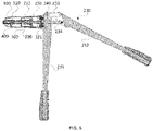
- the pipe flaring device comprises: an installation housing 100, a transmission mechanism 200, the flaring bulge ring 300 and the introduction mechanism 400.
- the installation housing 100 is provided with a flaring cavity 110 allowing the pipe to be inserted.
- the introduction mechanism 400 is located in the flaring cavity 110, the flaring bulge ring 300 is sleeved over (outside) the introduction mechanism 400.
- the introduction mechanism 400 is connected with the transmission mechanism 200, and the transmission mechanism 200 is configured to drive the introduction mechanism 400 to move in the flaring cavity 110, the introduction mechanism 400 is configured to extend into the pipe, and the flaring bulge ring 300 is configured to circumferentially abut against the port of the pipe.
- the end size of the introduction mechanism 400 is determined according to the diameter of the end of the pipe, that is, it ensures that the introduction mechanism 400 can be smoothly inserted into the pipe. Then, according to the flaring requirements, the protruding diameter of the flaring bulge ring 300 on the introduction mechanism 400 is determined, such that after the flaring bulge ring 300 abuts against the port of the pipe, the size of the port of the pipe can be directly expanded to the preset port size.
- the introduction mechanism 400 and the flaring bulge ring 300 will move toward the direction of inserting into the pipe, and the introduction mechanism 400 will be inserted into the pipe before the flaring bulge ring 300.
- the introduction mechanism 400 will continue moving until the flaring bulge ring 300 circumferentially abuts against the port of the pipe, and at this time, the introduction mechanism 400 moves in the pipe, which can avoid the misalignment of the flaring bulge ring 300 and the port of the pipe.
- the above-mentioned pipe flaring device utilizes the flaring bulge ring 300 to realize the uniform circumferential abutting against the pipe port, and that is, it ensures uniform force acting on the pipe during flaring.
- the transmission mechanism 200 comprises a supporting seat 210, a transmission rod 220, a force-applying assembly 230 and the connecting assembly 240.
- the supporting seat 210 is provided with a guide sleeve 211, and the guide sleeve 211 is installed in the flaring cavity 110, and the supporting seat 210 and the installation housing 100 are installed and cooperated with each other.
- the transmission rod 220 has one end which is connected with the force-applying assembly 230 via the connecting assembly 240, and the other end passing through the guide sleeve 211 to be connected with the introduction mechanism 400. Referring to FIG. 5 and FIG.
- the force-applying assembly 230 comprises a first force-applying arm 231, a second force-applying arm 232, a rotating member 233 and the force transmission member 234, wherein the first force-applying arm 231 and the second force-applying arm 232 are rotatably cooperated through the rotating member 233, the first force-applying arm 231 and the supporting seat 210 are fixedly cooperated.
- the first force-applying arm 231 is provided with an assembling hole.
- One end of the force transmission member 234 is connected with the second force-applying arm 232, and the other end of the force transmission member 234 is connected with the connecting component 240 through the assembling hole.
- the rotating member 233 comprises a connecting rod and a rotating shaft, that is, both ends of the connecting rod realize the rotating cooperation between the rotating member 233 and the first force-applying arm 231 and the rotating cooperation between the rotating member 233 and the second force-applying arm 232, through the rotating shaft.
- the force transmission member 234 is a force transmission post or force transmission rod.
- the guide sleeve 211 is installed on one of end surfaces of the supporting seat 210, and the supporting seat 210 and the installation housing 100 can be connected and fixed using bolts or screws, and the supporting seat 210 and the installation housing 100 can also be fixed through snap-fit and snapping groove, or the supporting seat 210 and the installation housing 100 are movably cooperated with each other.
- the connecting assembly 240 can comprise a first connecting seat 241, and the first connecting seat 241 is connected with the transmission rod 220.
- an adapting seat 221 can be additionally provided on the transmission rod 220, that is, the first connecting seat 241 is sleeved on the adapting seat 221, and at the same time, it can be fixed by means of a second fastener 248 (bolt or screw).
- the first connecting seat 241 is provided with a snapping groove, and the end of the force transmission member 234 is provided with a snapping ring or a snap-fit adapting to the snapping groove. At this time, the first force-applying arm 231 and the supporting seat 210 are threadedly fixed.
- connecting assembly 240 can comprise a third fastener 249, a second connecting seat 242, a third connecting seat 243, a first clip 244, a second clip 245, the first spring 246 and the second spring 247, wherein the third fastener 249 is a bolt or screw.
- the end of the transmission rod 220 is provided with a first connecting thread, and a second connecting thread matched with the first connecting thread is provided on the second connecting seat 242.
- the transmission rod 220 is fixedly cooperated with the second connecting seat 242, and the third connecting seat 243 and the second connecting seat 242 are fixed through a third fastener 249.
- the third connecting seat 243 is provided with a mounting slot 2431, and both the first clip 244 and the second clip 245 can be installed in the mounting slot 2431.
- the second connecting seat 242 will block openings of two ends of the mounting slot 2431.
- the first clip 244 abuts against one of the ports of the mounting slot 2431 through the first spring 246.
- the second clip 245 abuts against another port of the mounting slot 2431 through the second spring 247.
- the third connecting seat 243 is provided with a mounting opening allowing the force transmission member 234 to be inserted. After the force transmission member 234 is inserted into the third connecting seat 243 through the mounting opening, the first clip 244 and the second clip 245 will elastically abut against the force transmission member 234, thereby realizing the connection and fixation between the connection assembly 240 and the force-applying assembly 230.
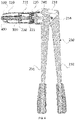
- the introduction mechanism 400 comprises a protection cover 410, a pipe-gripping sleeve 420 and a first elastic abutting member 430.
- the pipe-gripping sleeve 420 is connected with the guide sleeve 211, and the first elastic abutting member 430 is movably connected with the pipe-gripping sleeve 420.
- a plurality of fixing tooth slots 421 are arranged on the side wall of the pipe-gripping sleeve 420 along the circumferential direction of the pipe-gripping sleeve 420, and the fixing teeth 431 corresponding to the fixing tooth slots 421 are provided on the first elastic abutting member 430 along the circumferential direction of the first elastic abutting member 430.
- the first elastic abutting member 430 is used for elastically abutting against the transmission rod 220, and the protection cover 410 is sleeved over the first elastic abutting member 430.
- the protection cover 410 is a rigid cover.
- the first elastic abutting member 430 is an elastic cover, or the first elastic abutting member 430 comprises a plurality of elastic sheets.
- the multiple elastic sheets are spliced around the circumferential direction of the pipe-gripping sleeve 420, and one ends of the multiple elastic sheets are fixed, and the other ends of multiple elastic sheets are inserted into the pipe-gripping sleeve 420 and movably connected with the pipe-gripping sleeve 420.
- the transmission rod 220 is inserted into the first elastic abutting member 430 through the pipe-gripping sleeve 420, and at this time, the plurality of elastic sheets will elastically expand.
- the rigid protection cover 410 is sleeved over the first elastic abutting member 430, and then the protection cover 410 can play the role of protecting the first elastic abutting member 430.
- the elastic sheets can be driven by the transmission rod 220 to expand elastically, realizing that the fixing teeth 431 can protrude from the fixing slots 421, that is, it realizes the circumferential abutting between the fixing teeth 431 and the inner wall of the pipe, and ensures that the pipe does not move when the flaring bulge ring 300 enters the port of the pipe.
- the introduction mechanism 400 further comprises a first flaring seat 440
- the transmission mechanism 200 further comprises a first fastener 250
- the flaring bulge ring 300 is mounted on the first flaring seat 440
- the first flaring seat 440 is movably sleeved over the guide sleeve 211.
- the strip-shaped opening 212 is provided on the guide sleeve 211 along the axial direction of the guide sleeve 211.
- the first flaring seat 440 is provided with a first fixing hole fixedly cooperated with the first fastener 250.
- the transmission rod 220 is provided with a second fixing hole fixedly cooperated with the first fastener 250, and the second fixing hole is corresponding to the strip-shaped opening 212 in position.
- the first flaring seat 440 is fixedly cooperated with the transmission rod 220 through the first fastener 250.
- the first fastener 250 is a latch.
- the first flaring seat 440 is fixedly cooperated with the transmission rod 220 through the first fastener 250, and at the same time, the fixing ring 441 can be sleeved over a first flaring seat 440, and the fixing ring 441 covers the first fastener 250, so as to prevent the first fastener 250 from falling off from the first flaring seat 440.
- the long-side direction of the strip-shaped opening 212 is consistent with the movement direction of the transmission rod 220.
- the transmission rod 220 can drive the first flaring seat 440 to move within the opening range of the strip-shaped opening 212, and finally is inserted into the pipe through the first flaring seat 440, and the first flaring seat 440 flares the port of the pipe through the flaring bulge ring 300.
- the above-mentioned embodiment can ensure that the first flaring seat 440 moves in the preset direction, so that the first flaring seat 440 can enter the pipe more smoothly.
- the protection cover 410 firstly abuts against the side wall of the pipe, and then the first flaring seat 440 is inserted into the pipe for flaring. This embodiment described above increases contact area between the introduction mechanism 400 and the pipe, so that the pipe is subjected to more uniform force during flaring.
- the introduction mechanism 400 further comprises a second flaring seat 450.
- a plurality of fixing members 451 are provided on the second flaring seat 450 at intervals along the circumferential direction of the second flaring seat 450.
- the supporting seat 210 is provided with a mounting hole 213 allowing the fixing member 451 to pass through.
- the flaring bulge ring 300 is mounted on the second flaring seat 450.
- the second flaring seat 450 is movably sleeved over the guide sleeve 211.
- the fixing member 451 is fixedly cooperated with the connecting assembly 240.
- the fixing member 451 is a protruding strip or a rod body.
- the second flaring seat 450 is sleeved over the guide sleeve 211, and then by forming in the supporting seat 210 the mounting hole 213 allowing the fixing member 451 to pass through, it realizes that the second flaring seat 450 can pass through the supporting seat 210 to be connected with the force transmission mechanism, that is, it realizes the movable cooperation between the second flaring seat 450 and the guide sleeve 211.
- the second flaring seat 450 is inserted into the pipe, and the second flaring seat 450 uses the flaring bulge ring 300 to flare the port of the pipe.
- the above-mentioned embodiment can ensure that the second flaring seat 450 moves in a preset direction, so that the second flaring seat 450 can enter the pipe more smoothly.
- the introduction mechanism 400 includes a buffer sleeve 460, a second elastic abutting member 470 and a buffer ring 480.
- the second elastic abutting member 470 is movably connected with the guide sleeve 211.
- the second elastic abutting member 470 is used for elastically abutting against the transmission rod 220.
- the buffer sleeve 460 and the buffer ring 480 are both sleeved on the second elastic abutting member 470, and the buffer sleeve 460 and the buffer ring 480 are both used to abut against the pipe wall of the pipe.
- the buffer sleeve 460 and the buffer ring 480 are flexible resin or rubber.
- the second elastic abutting member 470 is an elastic cover, or the second elastic abutting member 470 includes a plurality of elastic sheets.
- the plurality of elastic sheets which are around the guide sleeve 211, are spliced along the circumferential direction thereof. One ends of the plurality of elastic sheets are fixed, and the other ends of the plurality of elastic sheets are inserted into the guide sleeve 211 and movably connected with the guide sleeve 211.
- the transmission rod 220 is inserted into the second elastic abutting member 470 through the guide sleeve 211, and at this time, the plurality of elastic sheets will be elastically expanded.
- the buffer sleeve 460 and the buffer ring 480 are disposed outside the second elastic abutting member 470, that is, the buffer sleeve can be elastically expanded along with the second elastic abutting member 470.
- the above-mentioned embodiment can prevent the plurality of elastic sheets from directly contacting the pipe wall of the pipe, so as to avoid forming a plurality of ribs on the inner wall of the pipe when the pipe is flared (the existence of the ribs can easily lead to cracking of the pipe).
- both the buffer sleeve 460 and the second abutting member 470 can be integrally formed with the guide sleeve 211. That is, when the transmission rod 220 moves toward the second abutting member 470 inside the guide sleeve 211, the second abutting member 470 can be expanded in the circumferential direction under the push of the transmission rod 220, so as to realize the circumferential abutting between the second abutting member 470 and the inner wall of the pipe.
- the pipe flaring device further includes a first positioning seat 500.
- the first positioning seat 500 is installed inside the installation housing 100.
- the end surface of the first positioning seat 500 is used to abut against the port of the pipe.
- the first positioning seat 500 is provided with a first adapting port 510 allowing the introduction mechanism 400 to pass therethrough.
- the end of the first positioning seat 500 is provided with a first abutting portion 520.
- the installation housing 100 is provided with a second abutting portion 120 that is abutted and cooperated with the first abutting portion 520.
- the first abutting portion 520 on the first positioning seat 500 is an abutting plate or an annular convex ring.
- the second abutting portion 120 of the installation housing 100 may be a stepped groove formed directly on the installation housing 100, or a stepped groove formed by making an annular plate inserted inside the installation housing 100. Further, the first positioning seat 500 is installed inside the installation housing 100.
- the installation housing 100 and the supporting seat 210 are connected and fixed to each other, one of surfaces of the first abutting portion 520 abuts against the supporting seat 210, and another surface of the first abutting portion 520 abuts against the second abutting portion 120, thereby realizing that the first positioning seat 500 is fixed inside the installation housing 100.
- the pipe After the pipe is inserted into the flaring cavity 110, the pipe will abut against the end surface of the first positioning seat 500, so that it is realized that the insertion depth of the pipe in the flaring cavity 110 is fixed.
- the pipe flaring device further includes a second positioning seat 600.
- the second positioning seat 600 is installed inside the installation housing 100. The end surface of the second positioning seat 600 is used to abut against the port of the pipe.
- the second positioning seat 600 is provided with a second adapting port 610 allowing the introduction mechanism 400 to pass therethrough.
- the second positioning seat 600 is provided with a limiting member 620.
- a first thread is provided along the circumferential direction of the installation housing 100, and a second thread is provided along the circumferential direction of the second positioning seat 600.
- the supporting seat 210 is provided with a limiting opening 214 adapted to the limiting member 620.
- the limiting member 620 passes through the limiting opening 214 along the axial direction of the installation housing 100 and is connected to the connecting assembly 240, and the first thread is threadedly matched with the second thread.
- a scale mark hole 130 for measuring the depth position of the second positioning seat 600 in the installation housing is provided along the axial direction of the installation housing 100.
- the installation housing 100 and the supporting seat 210 can rotate relative to each other.
- a sliding chute is provided on the inner wall of the installation housing, along the circumferential direction of the inner wall of the installation housing 100, and at the same time, a threaded hole corresponding to the sliding chute is provided on the supporting seat 210.
- the limiting member 620 is a limiting plate or a limiting rod. After the limiting member 620 is inserted into the limiting opening 214, the supporting seat 210 can limit the rotation of the second positioning seat 600 inside the installation housing 100. Meanwhile, the limiting member 620 can change the depth of the limiting member 620 inserted into the limiting opening 214 along the axial direction of the installation housing 100.
- the installation housing 100 can be rotatably cooperated with the supporting seat 210 (for example, the installation housing 100 is directly sleeved outside the supporting seat 210, and meanwhile the installation housing 100 can rotate relative to the supporting seat 210, and at the same time, it is also possible that a rubber ring 215 is additionally installed between the installation housing 100 and the supporting seat 210, to reduce the friction between the installation housing and the supporting seat 210).
- the second positioning seat 600 will move relative to the installation housing 100 under the cooperation of the first thread and the second thread, thereby changing the distance between the second positioning seat 600 and the end of the installation housing 100. That is, the depth of the pipe inserted into the flaring cavity 110 can be changed.
- by adding a scale mark hole 130 on the installation housing 100 it is possible to effectively learn the specific depth of the pipe inserted into the flaring cavity 110. That is, the above-mentioned embodiment can improve the usability of the pipe flaring device.
- orientation or position relationship indicated by terms “center”, “longitudinal”, “lateral”, “length”, “width”, “thickness”, “upper”, “lower”, “front”, “back”, “left”, “right”, “vertical”, “ horizontal”, “top”, “bottom”, “inner”, “outer”, “clockwise”, “counterclockwise”, “axial”, “radial”, “circumferential direction” and the like, are based on the orientation or position relationship shown in the drawings, and only for the convenience of describing the present application and simplifying the description, rather than indicating or implying that the device or element referred to must be in the particular orientation, or constructed and operated in the particular orientation, and therefore should not be construed as limitations on the present application.
- first and second are only used for the purpose of description, and should not be construed as indicating or implying the importance of relativity or implying the number of indicated technical features. Thus, if a feature is defined by “first” or “second”, it may expressly or implicitly comprise at least one feature.
- plural means at least two, such as, two, three, etc., unless expressly and specifically defined otherwise.
- install should be understood in a broad sense. For example, it can be fixedly connected, detachably connected, or integrally formed.
- first and second features when a first feature is “on” or “under” a second feature, the first and second features may be directly contacted with each other, or the first and second features are indirectly contacted with each other through an intermediate medium.
- first feature when the first feature is “above”, “over” and “on” the second feature, it may mean that the first feature is directly above or obliquely above the second feature, or simply means that the first feature is on the level higher than that of the second feature.
- first feature When the first feature is “below”, “underneath” and “under” the second feature, it may mean that the first feature is directly below or obliquely below the second feature, or simply means that the first feature is on the level lower than that of the second feature.
Landscapes
- Engineering & Computer Science (AREA)
- Mechanical Engineering (AREA)
- Mutual Connection Of Rods And Tubes (AREA)
- Quick-Acting Or Multi-Walled Pipe Joints (AREA)
- Pipe Accessories (AREA)
- Manufacturing Of Tubular Articles Or Embedded Moulded Articles (AREA)
Applications Claiming Priority (2)
| Application Number | Priority Date | Filing Date | Title |
|---|---|---|---|
| CN202022608653.1U CN214211962U (zh) | 2020-11-12 | 2020-11-12 | 管材扩口装置 |
| PCT/CN2021/088128 WO2022100000A1 (fr) | 2020-11-12 | 2021-04-19 | Dispositif d'évasement de tuyau |
Publications (4)
| Publication Number | Publication Date |
|---|---|
| EP4063038A1 true EP4063038A1 (fr) | 2022-09-28 |
| EP4063038A4 EP4063038A4 (fr) | 2023-07-26 |
| EP4063038B1 EP4063038B1 (fr) | 2025-08-27 |
| EP4063038C0 EP4063038C0 (fr) | 2025-08-27 |
Family
ID=77696975
Family Applications (1)
| Application Number | Title | Priority Date | Filing Date |
|---|---|---|---|
| EP21890535.4A Active EP4063038B1 (fr) | 2020-11-12 | 2021-04-19 | Dispositif d'évasement de tuyau |
Country Status (7)
| Country | Link |
|---|---|
| EP (1) | EP4063038B1 (fr) |
| CN (1) | CN214211962U (fr) |
| AU (1) | AU2021379629B2 (fr) |
| ES (1) | ES3040792T3 (fr) |
| GB (2) | GB202209874D0 (fr) |
| WO (1) | WO2022100000A1 (fr) |
| ZA (1) | ZA202207116B (fr) |
Families Citing this family (1)
| Publication number | Priority date | Publication date | Assignee | Title |
|---|---|---|---|---|
| CN112475068B (zh) * | 2020-11-12 | 2024-11-05 | 日丰企业(佛山)有限公司 | 管材扩口装置 |
Family Cites Families (12)
| Publication number | Priority date | Publication date | Assignee | Title |
|---|---|---|---|---|
| DE19843560A1 (de) * | 1998-09-23 | 2000-03-30 | Rheinauer Maschinen & Armature | Verfahren zur Herstellung einer Gehäusehalbschale für eine Absperrarmatur und Vorrichtung zur Durchführung des Verfahrens |
| EP2600993A4 (fr) * | 2010-08-06 | 2017-07-12 | American Grease Stick Company | Outil à évaser à main |
| DE102013105481A1 (de) * | 2013-05-28 | 2014-12-04 | Daniel Knipping | Aufweitung von Rohren |
| CN103878259A (zh) * | 2014-03-17 | 2014-06-25 | 刘战晓 | 新型全自动钢管扩口机 |
| CN204977432U (zh) * | 2015-09-11 | 2016-01-20 | 河北万利泰欧勒管业有限公司 | 一种塑料管材扩口模具 |
| JP6741223B2 (ja) * | 2016-03-25 | 2020-08-19 | 株式会社ノーリツ | 継手管の製造方法およびその装置 |
| US10940521B2 (en) * | 2017-06-29 | 2021-03-09 | Milwaukee Electric Tool Corporation | Swage tool |
| US20190283106A1 (en) * | 2018-03-14 | 2019-09-19 | Yung Chi Industry Co., Ltd. | Tube positioning device of tube flaring tool |
| CN208912894U (zh) * | 2018-10-30 | 2019-05-31 | 山东哈船船舶装备制造有限公司 | 一种铝蜂窝芯拉伸机 |
| CN110154369A (zh) * | 2019-05-24 | 2019-08-23 | 日丰科技有限公司 | 一种扩口钳 |
| CN210305402U (zh) * | 2019-07-26 | 2020-04-14 | 陈旭生 | 一种旋转式扩孔器 |
| CN112475068B (zh) * | 2020-11-12 | 2024-11-05 | 日丰企业(佛山)有限公司 | 管材扩口装置 |
-
2020
- 2020-11-12 CN CN202022608653.1U patent/CN214211962U/zh active Active
-
2021
- 2021-04-19 ES ES21890535T patent/ES3040792T3/es active Active
- 2021-04-19 GB GBGB2209874.3A patent/GB202209874D0/en not_active Ceased
- 2021-04-19 EP EP21890535.4A patent/EP4063038B1/fr active Active
- 2021-04-19 GB GB2209317.3A patent/GB2618164B/en active Active
- 2021-04-19 AU AU2021379629A patent/AU2021379629B2/en active Active
- 2021-04-19 WO PCT/CN2021/088128 patent/WO2022100000A1/fr not_active Ceased
-
2022
- 2022-06-27 ZA ZA2022/07116A patent/ZA202207116B/en unknown
Also Published As
| Publication number | Publication date |
|---|---|
| CN214211962U (zh) | 2021-09-17 |
| GB202209874D0 (en) | 2022-08-17 |
| EP4063038A4 (fr) | 2023-07-26 |
| NZ789687A (en) | 2025-05-02 |
| AU2021379629A1 (en) | 2022-07-14 |
| WO2022100000A1 (fr) | 2022-05-19 |
| EP4063038B1 (fr) | 2025-08-27 |
| AU2021379629B2 (en) | 2024-08-01 |
| ES3040792T3 (en) | 2025-11-05 |
| GB202209317D0 (en) | 2022-08-10 |
| EP4063038C0 (fr) | 2025-08-27 |
| GB2618164A (en) | 2023-11-01 |
| ZA202207116B (en) | 2023-05-31 |
| GB2618164B (en) | 2024-10-02 |
Similar Documents
| Publication | Publication Date | Title |
|---|---|---|
| AU2021379629B2 (en) | Pipe flaring device | |
| CN108288797B (zh) | 一种可调节安装的电源连接器 | |
| US20050072277A1 (en) | Torque wrench | |
| US20110011219A1 (en) | Screwdriver | |
| CN110153942B (zh) | 挠性环嵌入装置 | |
| CN102597551A (zh) | 接触可见型轴承螺杆传送设备 | |
| CN112475068B (zh) | 管材扩口装置 | |
| TWI852253B (zh) | 鉸鏈裝置 | |
| CN119509296A (zh) | 一种具有半月槽的轴检测装置 | |
| US11304326B2 (en) | Electronic device having electronic components connected with each other without gaps | |
| CN108119443A (zh) | 一种被动伸缩夹紧机构 | |
| US11255380B2 (en) | Bearing assembly and rotary shaft apparatus employing same | |
| CN211623987U (zh) | 一种方便操作的自动锁紧卡紧装置 | |
| KR20230112839A (ko) | 전동공구 | |
| WO2020084857A1 (fr) | Élément de montage | |
| CN222557746U (zh) | 一种用于墙内安装的预埋盒 | |
| CN218225432U (zh) | 一种吨桶旋盖用浮动旋爪机构 | |
| CN215830196U (zh) | 方钢长度可调的执手及门窗 | |
| CN114598250B (zh) | 调节支架和光伏发电装置 | |
| CN221153932U (zh) | 一种具有定位功能的支架结构及盖板 | |
| CN1204321C (zh) | 连接夹子和采用该连接夹子的用于马桶组件的卫生器具 | |
| WO2020084856A1 (fr) | Dispositif de mise à la terre de câble | |
| CN209466168U (zh) | 用于螺栓组件的辅助安装装置 | |
| CN115415722A (zh) | 定位装置 | |
| CN212080085U (zh) | 一种一体化成型同步轮 |
Legal Events
| Date | Code | Title | Description |
|---|---|---|---|
| STAA | Information on the status of an ep patent application or granted ep patent |
Free format text: STATUS: THE INTERNATIONAL PUBLICATION HAS BEEN MADE |
|
| PUAI | Public reference made under article 153(3) epc to a published international application that has entered the european phase |
Free format text: ORIGINAL CODE: 0009012 |
|
| STAA | Information on the status of an ep patent application or granted ep patent |
Free format text: STATUS: REQUEST FOR EXAMINATION WAS MADE |
|
| 17P | Request for examination filed |
Effective date: 20220623 |
|
| AK | Designated contracting states |
Kind code of ref document: A1 Designated state(s): AL AT BE BG CH CY CZ DE DK EE ES FI FR GB GR HR HU IE IS IT LI LT LU LV MC MK MT NL NO PL PT RO RS SE SI SK SM TR |
|
| STAA | Information on the status of an ep patent application or granted ep patent |
Free format text: STATUS: EXAMINATION IS IN PROGRESS |
|
| A4 | Supplementary search report drawn up and despatched |
Effective date: 20230622 |
|
| RIC1 | Information provided on ipc code assigned before grant |
Ipc: B29C 57/04 20060101ALI20230616BHEP Ipc: B21D 41/02 20060101AFI20230616BHEP |
|
| 17Q | First examination report despatched |
Effective date: 20230704 |
|
| DAV | Request for validation of the european patent (deleted) | ||
| DAX | Request for extension of the european patent (deleted) | ||
| GRAP | Despatch of communication of intention to grant a patent |
Free format text: ORIGINAL CODE: EPIDOSNIGR1 |
|
| STAA | Information on the status of an ep patent application or granted ep patent |
Free format text: STATUS: GRANT OF PATENT IS INTENDED |
|
| INTG | Intention to grant announced |
Effective date: 20250224 |
|
| GRAS | Grant fee paid |
Free format text: ORIGINAL CODE: EPIDOSNIGR3 |
|
| GRAA | (expected) grant |
Free format text: ORIGINAL CODE: 0009210 |
|
| STAA | Information on the status of an ep patent application or granted ep patent |
Free format text: STATUS: THE PATENT HAS BEEN GRANTED |
|
| AK | Designated contracting states |
Kind code of ref document: B1 Designated state(s): AL AT BE BG CH CY CZ DE DK EE ES FI FR GB GR HR HU IE IS IT LI LT LU LV MC MK MT NL NO PL PT RO RS SE SI SK SM TR |
|
| REG | Reference to a national code |
Ref country code: CH Ref legal event code: EP |
|
| REG | Reference to a national code |
Ref country code: IE Ref legal event code: FG4D |
|
| U01 | Request for unitary effect filed |
Effective date: 20250902 |
|
| U07 | Unitary effect registered |
Designated state(s): AT BE BG DE DK EE FI FR IT LT LU LV MT NL PT RO SE SI Effective date: 20250908 |
|
| REG | Reference to a national code |
Ref country code: ES Ref legal event code: FG2A Ref document number: 3040792 Country of ref document: ES Kind code of ref document: T3 Effective date: 20251105 |
|
| GRAT | Correction requested after decision to grant or after decision to maintain patent in amended form |
Free format text: ORIGINAL CODE: EPIDOSNCDEC |
|
| REG | Reference to a national code |
Ref country code: CH Ref legal event code: W10 Free format text: ST27 STATUS EVENT CODE: U-0-0-W10-W00 (AS PROVIDED BY THE NATIONAL OFFICE) Effective date: 20251112 |
|
| RAP4 | Party data changed (patent owner data changed or rights of a patent transferred) |
Owner name: RIFENG TECHNOLOGY CO., LTD. Owner name: RIFENG ENTERPRISE (FOSHAN) CO., LTD. Owner name: RIFENG ENTERPRISE GROUP CO., LTD. |
|
| U1H | Name or address of the proprietor changed after the registration of the unitary effect |
Owner name: RIFENG ENTERPRISE (FOSHAN) CO., LTD.; CN Owner name: RIFENG ENTERPRISE GROUP CO., LTD.; CN Owner name: RIFENG TECHNOLOGY CO., LTD.; CN |
|
| PG25 | Lapsed in a contracting state [announced via postgrant information from national office to epo] |
Ref country code: IS Free format text: LAPSE BECAUSE OF FAILURE TO SUBMIT A TRANSLATION OF THE DESCRIPTION OR TO PAY THE FEE WITHIN THE PRESCRIBED TIME-LIMIT Effective date: 20251227 |
|
| PG25 | Lapsed in a contracting state [announced via postgrant information from national office to epo] |
Ref country code: NO Free format text: LAPSE BECAUSE OF FAILURE TO SUBMIT A TRANSLATION OF THE DESCRIPTION OR TO PAY THE FEE WITHIN THE PRESCRIBED TIME-LIMIT Effective date: 20251127 |
|
| PG25 | Lapsed in a contracting state [announced via postgrant information from national office to epo] |
Ref country code: HR Free format text: LAPSE BECAUSE OF FAILURE TO SUBMIT A TRANSLATION OF THE DESCRIPTION OR TO PAY THE FEE WITHIN THE PRESCRIBED TIME-LIMIT Effective date: 20250827 |
|
| PG25 | Lapsed in a contracting state [announced via postgrant information from national office to epo] |
Ref country code: GR Free format text: LAPSE BECAUSE OF FAILURE TO SUBMIT A TRANSLATION OF THE DESCRIPTION OR TO PAY THE FEE WITHIN THE PRESCRIBED TIME-LIMIT Effective date: 20251128 |
|
| PG25 | Lapsed in a contracting state [announced via postgrant information from national office to epo] |
Ref country code: PL Free format text: LAPSE BECAUSE OF FAILURE TO SUBMIT A TRANSLATION OF THE DESCRIPTION OR TO PAY THE FEE WITHIN THE PRESCRIBED TIME-LIMIT Effective date: 20250827 |
|
| PG25 | Lapsed in a contracting state [announced via postgrant information from national office to epo] |
Ref country code: RS Free format text: LAPSE BECAUSE OF FAILURE TO SUBMIT A TRANSLATION OF THE DESCRIPTION OR TO PAY THE FEE WITHIN THE PRESCRIBED TIME-LIMIT Effective date: 20251127 |
|
| PG25 | Lapsed in a contracting state [announced via postgrant information from national office to epo] |
Ref country code: SM Free format text: LAPSE BECAUSE OF FAILURE TO SUBMIT A TRANSLATION OF THE DESCRIPTION OR TO PAY THE FEE WITHIN THE PRESCRIBED TIME-LIMIT Effective date: 20250827 |
|
| PGFP | Annual fee paid to national office [announced via postgrant information from national office to epo] |
Ref country code: GB Payment date: 20260306 Year of fee payment: 6 |
|
| PG25 | Lapsed in a contracting state [announced via postgrant information from national office to epo] |
Ref country code: CZ Free format text: LAPSE BECAUSE OF FAILURE TO SUBMIT A TRANSLATION OF THE DESCRIPTION OR TO PAY THE FEE WITHIN THE PRESCRIBED TIME-LIMIT Effective date: 20250827 |
|
| PG25 | Lapsed in a contracting state [announced via postgrant information from national office to epo] |
Ref country code: SK Free format text: LAPSE BECAUSE OF FAILURE TO SUBMIT A TRANSLATION OF THE DESCRIPTION OR TO PAY THE FEE WITHIN THE PRESCRIBED TIME-LIMIT Effective date: 20250827 |