EP4063254A1 - Bouée intelligente - Google Patents
Bouée intelligente Download PDFInfo
- Publication number
- EP4063254A1 EP4063254A1 EP22159133.2A EP22159133A EP4063254A1 EP 4063254 A1 EP4063254 A1 EP 4063254A1 EP 22159133 A EP22159133 A EP 22159133A EP 4063254 A1 EP4063254 A1 EP 4063254A1
- Authority
- EP
- European Patent Office
- Prior art keywords
- buoy
- floating body
- watercraft
- identification information
- electronic unit
- Prior art date
- Legal status (The legal status is an assumption and is not a legal conclusion. Google has not performed a legal analysis and makes no representation as to the accuracy of the status listed.)
- Withdrawn
Links
- 238000007667 floating Methods 0.000 claims abstract description 39
- 230000001133 acceleration Effects 0.000 claims abstract description 37
- 238000012544 monitoring process Methods 0.000 claims abstract description 20
- 230000005540 biological transmission Effects 0.000 claims abstract description 17
- 238000011156 evaluation Methods 0.000 claims abstract description 7
- 238000000034 method Methods 0.000 claims abstract description 7
- 230000002457 bidirectional effect Effects 0.000 claims description 5
- 230000001939 inductive effect Effects 0.000 claims description 5
- 230000005294 ferromagnetic effect Effects 0.000 claims description 4
- 238000001514 detection method Methods 0.000 description 5
- 238000005516 engineering process Methods 0.000 description 5
- 229920005830 Polyurethane Foam Polymers 0.000 description 4
- 230000003213 activating effect Effects 0.000 description 4
- 239000011496 polyurethane foam Substances 0.000 description 4
- 230000005291 magnetic effect Effects 0.000 description 3
- 230000001413 cellular effect Effects 0.000 description 2
- 230000005611 electricity Effects 0.000 description 2
- 238000012423 maintenance Methods 0.000 description 2
- 238000007726 management method Methods 0.000 description 2
- 230000002093 peripheral effect Effects 0.000 description 2
- 239000013589 supplement Substances 0.000 description 2
- XLYOFNOQVPJJNP-UHFFFAOYSA-N water Substances O XLYOFNOQVPJJNP-UHFFFAOYSA-N 0.000 description 2
- 229920000049 Carbon (fiber) Polymers 0.000 description 1
- 239000000853 adhesive Substances 0.000 description 1
- 230000001070 adhesive effect Effects 0.000 description 1
- 238000013459 approach Methods 0.000 description 1
- 150000001721 carbon Chemical class 0.000 description 1
- 239000004917 carbon fiber Substances 0.000 description 1
- 238000013500 data storage Methods 0.000 description 1
- 239000003822 epoxy resin Substances 0.000 description 1
- 230000006698 induction Effects 0.000 description 1
- 239000002184 metal Substances 0.000 description 1
- 229920000647 polyepoxide Polymers 0.000 description 1
- 238000010248 power generation Methods 0.000 description 1
- 238000012545 processing Methods 0.000 description 1
Images
Classifications
-
- B—PERFORMING OPERATIONS; TRANSPORTING
- B63—SHIPS OR OTHER WATERBORNE VESSELS; RELATED EQUIPMENT
- B63B—SHIPS OR OTHER WATERBORNE VESSELS; EQUIPMENT FOR SHIPPING
- B63B22/00—Buoys
- B63B22/02—Buoys specially adapted for mooring a vessel
-
- B—PERFORMING OPERATIONS; TRANSPORTING
- B63—SHIPS OR OTHER WATERBORNE VESSELS; RELATED EQUIPMENT
- B63B—SHIPS OR OTHER WATERBORNE VESSELS; EQUIPMENT FOR SHIPPING
- B63B22/00—Buoys
- B63B2022/006—Buoys specially adapted for measuring or watch purposes
Definitions
- the invention relates to a buoy for attaching watercraft, which is provided with a floating body and an electronic unit with a transmitter for wireless data transmission and with photovoltaic elements for powering the electronic unit, the floating body being in an occupied state when the watercraft is attached and when it is absent of a fixed watercraft in an unoccupied state, according to the preamble of claim 1.
- the invention further relates to a method for monitoring the occupancy state of buoys of a buoy field with a buoy according to the invention, according to the preamble of claim 8.
- Buoy fields are used by watercraft to temporarily secure the watercraft and generally include a plurality of buoys that are anchored at a distance from one another on the lake or seabed near the shore.
- the watercraft can be attached to a fastening device of the buoy using a line.
- a fee has to be paid for the use of a buoy.
- the procedure is usually such that the watercraft approaches the buoy field, searches for a free buoy and moors at the free buoy. Subsequently, either a registration office on land must be visited in order to report the mooring and pay the fee, or the operator of the buoy field visits the watercraft by boat to record the vehicle data and collect the fee.
- the aim of the invention is therefore, on the one hand, to enable simple management of a buoy field with little personnel effort and, on the other hand, to be able to discover and thus penalize unauthorized occupancy of a buoy.
- Claim 1 relates to a buoy for attaching watercraft, which is provided with a floating body and an electronic unit with a transmitter for wireless data transmission and with photovoltaic elements for powering the electronic unit, the floating body being in an occupied state when the watercraft is attached and in the absence of an attached vessel in an unoccupied condition.
- the floating body is provided with an acceleration sensor for measuring acceleration data for the floating body, and the acceleration sensor is connected to an evaluation unit of the electronic unit, which is designed to separate the acceleration data measured by the acceleration sensor when it is unoccupied from the acceleration data when it is occupied measured acceleration data.
- a buoy is thus realized which can determine the occupancy status autonomously.
- This determination of the occupancy state is carried out using an acceleration sensor, since the applicant has found that it is easily possible to distinguish between an unoccupied state and an occupied state of the buoy using the measured acceleration data.
- This distinction is made, for example, with the help of the detection of acceleration peaks caused by a watercraft attached to the buoy because the watercraft attached to the buoy repeatedly tears and tugs at the buoy. Comparable acceleration peaks do not occur with an unoccupied buoy floating in the water and can therefore be used to reliably distinguish between occupied and unoccupied states.
- An appropriately configured evaluation unit A 9-axis acceleration sensor with three three-axis sensors can be used as the acceleration sensor be, namely an acceleration sensor, a gyroscope and a geomagnetic sensor. These three sensors ensure that extremely accurate acceleration data for acceleration, angular rate and earth's magnetic field can be determined, whereby such sensors can be optimized for the best performance with the lowest power consumption.
- occupancy state information The information about an occupied or unoccupied state of a buoy is also referred to below as occupancy state information.
- occupancy state information The information about an occupied or unoccupied state of a buoy is also referred to below as occupancy state information.
- the transmission device can be sent together with buoy identification information identifying the buoy to a central monitoring unit, where it is compared, for example, with corresponding reservation information for the relevant buoy.
- This transmission of the occupancy status information can be initiated autonomously by the buoy, for example when there is a change in the occupancy status information.
- the occupancy status information is initially only stored in a data memory of the buoy and is only called up by the central monitoring unit when required.
- the transmission device is designed as part of a network connection for the bidirectional exchange of data.
- the transmission device is designed as a network connection for a wide area network, for example as NB-IoT (Narrow Band Internet-of-Things), which is a "Low Power Wide Area (LPWA)" radio technology with low energy requirements and a long range for the bidirectional transmission of small data packets.
- NB-IoT Near Band Internet-of-Things
- LPWA Low Power Wide Area
- this Reservation information is transmitted to the buoy and is displayed accordingly on the buoy.
- the floating body is provided with a lighting means that can be activated via the network connection.
- the buoy can thus be marked as reserved for the watercraft by the central monitoring unit, for example by activating a red light, and as available by activating a green light, for example.
- the floating body is provided with an inductive sensor for detecting conductive or ferromagnetic objects.
- An inductive sensor detects the presence of conductive or ferromagnetic objects, particularly metal objects, by changing a magnetic field in the vicinity of such an object.
- the arrangement of such a sensor enables the detection of metallic components of a watercraft, for example its anchor or its engine block, and can be used to supplement the acceleration data in order to optimize the detection of an occupied state and in particular to detect double occupancy of a buoy, i.e the presence of a second vessel improperly attached to the same buoy.
- a specific embodiment of the buoy preferably provides that the floating body is formed by a lower floating body part that is rotationally symmetrical about a longitudinal axis of the floating body and an upper functional body part, with the functional body part having an outer surface that is at least partially formed from planar partial surfaces.
- the planar sub-areas can be used, for example, for the arrangement of photovoltaic elements in order to facilitate their attachment to the floating body and to optimize their positioning with regard to maximum power generation. However, they can also be used to facilitate removal of the electronic unit for maintenance or repair purposes. For this purpose, it is proposed in particular that the electronic unit is arranged in a housing that is embedded in the floating body and on a planar face is arranged adjacent. The electronic unit can thus be found easily if required, for example by also marking the corresponding planar sub-area accordingly, and subsequently also easily removed by providing access to the electronic unit via the covering sub-area.
- the floating body is provided with a short-range radio transmitter for the wireless transmission of buoy identification information identifying the buoy.
- the short-range radio transmitter is based, for example, on "Bluetooth Low Energy (BLE)" technology, with which data can be exchanged with other devices within a limited radius of 10-100 m. The power consumption can be kept very low.
- BLE Bluetooth Low Energy
- the invention also relates to a method for monitoring the occupancy status of buoys in a field of buoys with a buoy according to the invention, it being proposed that the evaluation unit of the electronic unit of the buoy identify the occupancy status of the relevant buoy using the acceleration sensor as an unoccupied status or as an occupied status , and this occupancy status information is sent together with a buoy identification information identifying the buoy via the transmitting device to a central monitoring unit.
- the occupancy status information can be compared with corresponding reservation information for the relevant buoy. If occupancy of the buoy is detected but no reservation information is available, a warning message can be generated in order to indicate to the operator of the buoy field an unauthorized occupancy of a buoy.
- the location of each buoy is known, for example by each buoy being provided with a GPS sensor which carries out an exact determination of the position of the relevant buoy.
- a corresponding monitoring and reservation system could be designed in such a way that user-specific operating software (e.g. as an "application” or “app”) is provided for mobile devices, via which an interested party can reserve a specific buoy for a buoy field of his choice and sometimes pay immediately can.
- the mobile radio terminal can be a mobile phone (“smartphone”), for example, or a tablet, a laptop, or any other device equipped with a router or gateway that can set up and use mobile radio connections.
- the reservation for a specific buoy is sent via the cellular connection to the central monitoring unit, where it is stored and used as reservation information, for example by activating a lamp arranged on the relevant buoy accordingly.
- the buoy identification information can be retrieved from the mobile radio terminal via a short-range radio transmitter of the buoy when a mobile radio terminal equipped with a short-range radio interface for receiving the buoy identification information is present in the transmission range of the short-range radio transmitter .
- the buoy identification information is sent from the mobile radio terminal via a mobile radio connection together with watercraft identification information that identifies the watercraft to the central monitoring unit, with the central monitoring unit using the buoy identification information to link the watercraft identification information to the occupancy status information in terms of data technology. It is thus possible to check whether the buoy is occupied and whether there is a reservation for this buoy, and whether the watercraft for which the reservation was made is at the correct buoy.
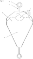
- FIG. 1 shows an embodiment of a buoy according to the invention with a rotationally symmetrical lower floating body part 1 and an upper functional body part 2, with the upper functional body part 2 covering the lower floating body part 1 in the manner of a hood and in a lower peripheral area tightly encompassing the upper peripheral area of the floating body part 1.
- Both parts consist of a laminated carbon fleece, i.e. a fleece made of carbon fibers, which is bonded with an epoxy resin.
- the interior of the floating body part 1 and the functional body part 2 are filled with polyurethane foam.
- the float portion 1 is frusto-conical about a longitudinal axis of the buoy defined by a stainless rod 3 crossing the buoy.
- the rod 3 has an eyelet at each of its upper and lower ends.
- the upper eyelet serves as a fastening device 4 for fastening the watercraft, and the lower eyelet serves for fastening to the underwater. After filling with the polyurethane foam, the lower floating body part 1 and the upper functional body part 2 together form the floating body of the buoy.
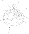
- the upper functional body part 2 has an outer surface which is at least partially formed from planar partial surfaces 5, such as in particular 2 can be removed.
- a top planar partial surface 5 also carries a shim 6 a nut 7, which serves to attach the rod 4.
- Photovoltaic elements 8 distributed around the circumference of the outer surface of the functional body part 2 are fastened to four of the planar partial surfaces 5 for generating electricity.
- On a further planar partial surface 5 there is a marking 9 and an access possibility to an underlying electronic unit in order to facilitate locating and accessing the electronic unit for maintenance or repair purposes.
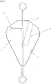
- the 3 shows the buoy according to 1 with an illustration of some internal components.
- the floating body part 1 and the functional body part 2 are filled with polyurethane foam, which ensures the tightness of the arrangement and serves as protection for the sensors and electronics embedded therein.
- a tubular housing 12 is placed so that it opens against a planar part surface 5 .
- the electronic unit can then be arranged in this housing 12, as will be explained in more detail below.
- an additional power source 13 is arranged, which converts kinetic energy of the buoy into electricity by shaking induction.
- the 3 two more temperature sensors 14, 15 can be removed.
- a lower temperature sensor 15 is used to determine the water temperature.
- An upper temperature sensor 14 is used to determine the air temperature.
- the photovoltaic elements 8 and the temperature sensors 14, 15 are connected to a printed circuit board of the electronic unit, which is arranged inside the housing 12.
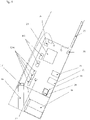
- the 4 shows a possible embodiment of such an electronic unit.
- the electronic unit has a circuit board which is initially connected to a power storage device 16 which supplies the electronic unit with power.
- the power storage 16 is of the photovoltaic elements 8 and the additional power source 13 charged via a charge controller 27.
- the electronic unit includes a GPS sensor 17, which is arranged on a support 18 and is used to determine the exact position of the buoy.
- An SD card slot 22 for local data storage and a slot 23 for a SIM card are also provided.
- the network connection 24 is provided by a modem and implemented, for example, as NB-IoT, which is an LPWA radio technology with a low energy requirement and a long range for the bidirectional transmission of small data packets.
- the circuit board is wired to an antenna as a transmission device 25, which is attached to the wall of the buoy, for example by means of adhesive strips.
- the circuit board of the electronic unit is also provided with an acceleration sensor 26, which can be designed, for example, as a 9-axis acceleration sensor with three three-axis sensors, namely an acceleration sensor, a gyroscope and a geomagnetic sensor. These three sensors ensure that extremely accurate acceleration data for acceleration, angular rate and earth's magnetic field can be determined, whereby such sensors can be optimized for the best performance with the lowest power consumption.
- the electronic unit is provided with an inductive sensor 28 for detecting conductive or ferromagnetic objects.
- an inductive sensor 28 enables the detection of metallic components of a watercraft, for example its anchor or its engine block, and can be used to supplement the acceleration data in order to optimize the detection of an occupied condition and in particular a To detect double occupancy of a buoy, i.e. the presence of a second watercraft that is illegally attached to the same buoy.
- the in the Figures 1-4 The buoy shown could be used in a monitoring and reservation system in which, for example, user-specific operating software (e.g. as an "application” or “app”) is provided for mobile radio terminals, via which an interested party can reserve a specific buoy for a buoy field of his choice and sometimes also can pay immediately.
- the mobile radio terminal can be a cell phone ("smartphone"), for example.
- the reservation for a specific buoy is made via the cellular connection to the central monitoring unit (in the Figures 1-4 not visible), where it is stored as reservation information and utilized by activating the lighting means 11 arranged on the relevant buoy accordingly.
- the boatman can register either via Bluetooth or using the buoy number, which can be entered in the app, whereupon the watercraft identification information can be compared with the buoy identification information with the Occupancy status information is linked in terms of data technology and the buoy in question is stored with the status "occupied”. It can also be checked whether the buoy is occupied and whether there is a reservation for this buoy, and whether the watercraft for which the reservation was made is at the correct buoy.
Landscapes
- Chemical & Material Sciences (AREA)
- Engineering & Computer Science (AREA)
- Combustion & Propulsion (AREA)
- Mechanical Engineering (AREA)
- Ocean & Marine Engineering (AREA)
- Arrangements For Transmission Of Measured Signals (AREA)
Applications Claiming Priority (1)
| Application Number | Priority Date | Filing Date | Title |
|---|---|---|---|
| AT600622021A AT525396A2 (de) | 2021-03-05 | 2021-03-05 | Smart buoy |
Publications (1)
| Publication Number | Publication Date |
|---|---|
| EP4063254A1 true EP4063254A1 (fr) | 2022-09-28 |
Family
ID=80595122
Family Applications (1)
| Application Number | Title | Priority Date | Filing Date |
|---|---|---|---|
| EP22159133.2A Withdrawn EP4063254A1 (fr) | 2021-03-05 | 2022-02-28 | Bouée intelligente |
Country Status (2)
| Country | Link |
|---|---|
| EP (1) | EP4063254A1 (fr) |
| AT (1) | AT525396A2 (fr) |
Citations (4)
| Publication number | Priority date | Publication date | Assignee | Title |
|---|---|---|---|---|
| EP1550086B1 (fr) * | 2002-10-07 | 2007-12-12 | Italgest Information Technology S.P.A. | Systeme permettant de commander et de gerer l'amarrage dans une zone de mer |
| CN106628006A (zh) * | 2016-12-28 | 2017-05-10 | 淮海工学院 | 一种智能手机波浪浮标 |
| FR3094337A1 (fr) * | 2019-03-28 | 2020-10-02 | Etm | Système d’amarrage comprenant une pluralite de bouees munies d’unites de communication |
| CN110422281B (zh) * | 2019-07-26 | 2021-01-19 | 山东蓝海可燃冰勘探开发研究院有限公司 | 海洋物联网智能浮标、水面或水下目标探测系统及其方法 |
-
2021
- 2021-03-05 AT AT600622021A patent/AT525396A2/de not_active Application Discontinuation
-
2022
- 2022-02-28 EP EP22159133.2A patent/EP4063254A1/fr not_active Withdrawn
Patent Citations (4)
| Publication number | Priority date | Publication date | Assignee | Title |
|---|---|---|---|---|
| EP1550086B1 (fr) * | 2002-10-07 | 2007-12-12 | Italgest Information Technology S.P.A. | Systeme permettant de commander et de gerer l'amarrage dans une zone de mer |
| CN106628006A (zh) * | 2016-12-28 | 2017-05-10 | 淮海工学院 | 一种智能手机波浪浮标 |
| FR3094337A1 (fr) * | 2019-03-28 | 2020-10-02 | Etm | Système d’amarrage comprenant une pluralite de bouees munies d’unites de communication |
| CN110422281B (zh) * | 2019-07-26 | 2021-01-19 | 山东蓝海可燃冰勘探开发研究院有限公司 | 海洋物联网智能浮标、水面或水下目标探测系统及其方法 |
Also Published As
| Publication number | Publication date |
|---|---|
| AT525396A2 (de) | 2023-03-15 |
Similar Documents
| Publication | Publication Date | Title |
|---|---|---|
| DE602004011425T2 (de) | Kommunikationssystem und Verfahren zum Kommunizieren zwischen Reifen/Rad-Einheit und Fahrzeugkarosserie | |
| DE102006033225B4 (de) | Manipulationserfassungssystem für Fahrzeugbauteile | |
| DE19716684B4 (de) | Anker-/Ankerketten-Überwachungsvorrichtung | |
| DE602004003787T2 (de) | Verfahren und Vorrichtung zur Nachrichtenlieferung | |
| DE102011018615B4 (de) | System, insbesondere Anlage, mit auf einem Boden verfahrbaren Fahrzeug | |
| DE102018210765A1 (de) | Lokalisierungssystem und Verfahren zum Betreiben desselben | |
| EP2637143B1 (fr) | Procédé de communication radio entre un capteur radio et une unité embarquée ainsi que capteur radio et unité embarquée associée | |
| EP1588900B1 (fr) | Disposif de lecture pour des capteurs dans le compartiment moteur d'un véhicule automobile | |
| EP4063254A1 (fr) | Bouée intelligente | |
| DE102008017790B4 (de) | Anordnung zur Identifizierung von Fahrzeuginsassen | |
| EP2502205A2 (fr) | Procédé pour générer une représentation d'un environnement | |
| DE102008043506A1 (de) | Gerät zur Erkennung von GNSS-Störsendern | |
| DE102005061249A1 (de) | Vorrichtung und Verfahren zur Prüfung und drahtlosen Übermittlung des Zustands eines Signalgebers | |
| DE102022116891A1 (de) | Flexible-Struktur, Flexible-Struktur-Anordnung und Flexible- Struktur-System | |
| CN205810130U (zh) | 一种校车使用的定位系统 | |
| DE60204138T2 (de) | System zum finden von fahrzeugen, die in gebäuden und oberflächen mit dach geparkt sind | |
| DE112005000571T5 (de) | System zur Überwachung eines Radzustandes | |
| WO2006079521A1 (fr) | Systeme et procede pour surveiller des objets groupes | |
| EP2963386B1 (fr) | Systeme de compas dote de transpondeur rfid | |
| AT521361B1 (de) | Zustellvorrichtung, Zustellsystem sowie Verfahren für die Zustellung von Sendungen | |
| DE19921759C2 (de) | Informationssystem und Verfahren zur Orientierung | |
| DE2137074A1 (de) | Verfahren und vorrichtung zum auffinden und verfolgen von schallabstrahlenden objekten im wasser | |
| DE10319114B4 (de) | Überwachung des Standorts eines geparkten Fahrzeugs | |
| DE102015212302B4 (de) | Verfahren und Vorrichtung zum Orten einer eine Parkfläche umfassenden Bodenplatte für einen Systemparkplatz | |
| DE102007039451A1 (de) | System zur Ortung beweglicher Objekte |
Legal Events
| Date | Code | Title | Description |
|---|---|---|---|
| PUAI | Public reference made under article 153(3) epc to a published international application that has entered the european phase |
Free format text: ORIGINAL CODE: 0009012 |
|
| STAA | Information on the status of an ep patent application or granted ep patent |
Free format text: STATUS: THE APPLICATION HAS BEEN PUBLISHED |
|
| AK | Designated contracting states |
Kind code of ref document: A1 Designated state(s): AL AT BE BG CH CY CZ DE DK EE ES FI FR GB GR HR HU IE IS IT LI LT LU LV MC MK MT NL NO PL PT RO RS SE SI SK SM TR |
|
| STAA | Information on the status of an ep patent application or granted ep patent |
Free format text: STATUS: THE APPLICATION IS DEEMED TO BE WITHDRAWN |
|
| 18D | Application deemed to be withdrawn |
Effective date: 20230329 |