EP4063653A1 - Volumetrische hochdruck-kolbenpumpe - Google Patents
Volumetrische hochdruck-kolbenpumpe Download PDFInfo
- Publication number
- EP4063653A1 EP4063653A1 EP22160445.7A EP22160445A EP4063653A1 EP 4063653 A1 EP4063653 A1 EP 4063653A1 EP 22160445 A EP22160445 A EP 22160445A EP 4063653 A1 EP4063653 A1 EP 4063653A1
- Authority
- EP
- European Patent Office
- Prior art keywords
- cylinder
- volumetric pump
- valve
- cylinder jacket
- valve body
- Prior art date
- Legal status (The legal status is an assumption and is not a legal conclusion. Google has not performed a legal analysis and makes no representation as to the accuracy of the status listed.)
- Granted
Links
Images


Classifications
-
- F—MECHANICAL ENGINEERING; LIGHTING; HEATING; WEAPONS; BLASTING
- F04—POSITIVE - DISPLACEMENT MACHINES FOR LIQUIDS; PUMPS FOR LIQUIDS OR ELASTIC FLUIDS
- F04B—POSITIVE-DISPLACEMENT MACHINES FOR LIQUIDS; PUMPS
- F04B53/00—Component parts, details or accessories not provided for in, or of interest apart from, groups F04B1/00 - F04B23/00 or F04B39/00 - F04B47/00
- F04B53/10—Valves; Arrangement of valves
- F04B53/109—Valves; Arrangement of valves inlet and outlet valve forming one unit
-
- F—MECHANICAL ENGINEERING; LIGHTING; HEATING; WEAPONS; BLASTING
- F04—POSITIVE - DISPLACEMENT MACHINES FOR LIQUIDS; PUMPS FOR LIQUIDS OR ELASTIC FLUIDS
- F04B—POSITIVE-DISPLACEMENT MACHINES FOR LIQUIDS; PUMPS
- F04B53/00—Component parts, details or accessories not provided for in, or of interest apart from, groups F04B1/00 - F04B23/00 or F04B39/00 - F04B47/00
- F04B53/10—Valves; Arrangement of valves
-
- F—MECHANICAL ENGINEERING; LIGHTING; HEATING; WEAPONS; BLASTING
- F04—POSITIVE - DISPLACEMENT MACHINES FOR LIQUIDS; PUMPS FOR LIQUIDS OR ELASTIC FLUIDS
- F04B—POSITIVE-DISPLACEMENT MACHINES FOR LIQUIDS; PUMPS
- F04B1/00—Multi-cylinder machines or pumps characterised by number or arrangement of cylinders
-
- F—MECHANICAL ENGINEERING; LIGHTING; HEATING; WEAPONS; BLASTING
- F04—POSITIVE - DISPLACEMENT MACHINES FOR LIQUIDS; PUMPS FOR LIQUIDS OR ELASTIC FLUIDS
- F04B—POSITIVE-DISPLACEMENT MACHINES FOR LIQUIDS; PUMPS
- F04B1/00—Multi-cylinder machines or pumps characterised by number or arrangement of cylinders
- F04B1/04—Multi-cylinder machines or pumps characterised by number or arrangement of cylinders having cylinders in star- or fan-arrangement
- F04B1/0404—Details or component parts
- F04B1/0452—Distribution members, e.g. valves
-
- F—MECHANICAL ENGINEERING; LIGHTING; HEATING; WEAPONS; BLASTING
- F04—POSITIVE - DISPLACEMENT MACHINES FOR LIQUIDS; PUMPS FOR LIQUIDS OR ELASTIC FLUIDS
- F04B—POSITIVE-DISPLACEMENT MACHINES FOR LIQUIDS; PUMPS
- F04B1/00—Multi-cylinder machines or pumps characterised by number or arrangement of cylinders
- F04B1/04—Multi-cylinder machines or pumps characterised by number or arrangement of cylinders having cylinders in star- or fan-arrangement
- F04B1/0404—Details or component parts
- F04B1/0452—Distribution members, e.g. valves
- F04B1/0456—Cylindrical
-
- F—MECHANICAL ENGINEERING; LIGHTING; HEATING; WEAPONS; BLASTING
- F04—POSITIVE - DISPLACEMENT MACHINES FOR LIQUIDS; PUMPS FOR LIQUIDS OR ELASTIC FLUIDS
- F04B—POSITIVE-DISPLACEMENT MACHINES FOR LIQUIDS; PUMPS
- F04B53/00—Component parts, details or accessories not provided for in, or of interest apart from, groups F04B1/00 - F04B23/00 or F04B39/00 - F04B47/00
- F04B53/16—Casings; Cylinders; Cylinder liners or heads; Fluid connections
-
- F—MECHANICAL ENGINEERING; LIGHTING; HEATING; WEAPONS; BLASTING
- F04—POSITIVE - DISPLACEMENT MACHINES FOR LIQUIDS; PUMPS FOR LIQUIDS OR ELASTIC FLUIDS
- F04B—POSITIVE-DISPLACEMENT MACHINES FOR LIQUIDS; PUMPS
- F04B53/00—Component parts, details or accessories not provided for in, or of interest apart from, groups F04B1/00 - F04B23/00 or F04B39/00 - F04B47/00
- F04B53/16—Casings; Cylinders; Cylinder liners or heads; Fluid connections
- F04B53/162—Adaptations of cylinders
- F04B53/166—Cylinder liners
Definitions
- the present invention relates to the field of piston volumetric pumps which can be installed on high-pressure cleaners or other machines for distributing and/or delivering fluids at high pressure, for example pressures in the order of 1500 bar.
- Piston volumetric pumps generally comprise an inlet manifold adapted to be connected to a tank containing the fluid to be pumped (typically water), a delivery manifold adapted to be connected to a fluid dispensing device (e.g. a lance or a dispensing gun) equipped with a terminal nozzle, and a regulating valve, hydraulically interposed between the delivery manifold and the dispensing device, which is designed to regulate the maximum delivery pressure of the fluid.
- a fluid dispensing device e.g. a lance or a dispensing gun
- piston volumetric pumps generally comprise a pump casing, defining one or more cylinders, and a head, attached to the pump casing and closing one end of each cylinder.
- An alternative piston is slidably accommodated inside each cylinder, which, together with the corresponding cylinder and head, defines a respective variable volume compression chamber.
- the pistons are kinematically connected to a drive shaft (eccentric) via a respective connecting rod-crank mechanism, which is designed to transform the rotary movement of the drive shaft, given by a drive motor, into a linear alternative movement of the piston.
- Each compression chamber is connected to the inlet manifold via a respective inlet check valve and to the discharge manifold via a respective delivery check valve.
- the high pressure of the fluid delivered by the end nozzle is guaranteed by the fluid sealing system on the pistons and the materials used to ensure adequate durability of the sealing system.
- a known sealing system consists, for each piston, of a high-pressure gasket of a stiffer material placed between the cylinder and the delivery valve body and a low-pressure gasket of a softer material placed between each cylinder and the pump head.
- the double gasket system is not particularly efficient because the high-pressure gasket, due to the high pulsating loads, tends, as it wears out, to let high-pressure fluid leak out, which quickly wears out the low-pressure gasket, causing fluid leakage that flows outside the pump casing.
- An object of the present invention is to overcome the mentioned drawbacks of the prior art, within the context of a simple and rational solution and at a contained cost.
- One aspect of the invention provides that the side wall of said central portion of the valve body of the delivery valve has an annular groove to increase the volume of the supply chamber.
- This solution lowers the pressure inside the supply chamber by facilitating the entry of fluid flowing from the high-pressure gasket into the supply chamber.
- valve body has a second portion whose free end comprises a valve seat of the delivery valve on which a shutter acts.
- a further aspect of the invention is that the second end portion is accommodated in a second cavity, preferably having circular section, which is derived from and coaxial with a back wall of the first cavity.
- a further aspect of the invention is that the cylinder jacket is inserted into an outer casing.
- a further aspect of the invention provides that the cylinder head is fixed to the outer casing.
- a further aspect of the invention provides for a low-pressure fluid inlet valve associated with the cylinder.
- the inlet valve comprises a shutter having an annular shape for obstructing the opening of the inlet duct and a central hole at the delivery duct.
- the annular shape of the delivery shutter has the advantage of making the shutter and therefore the inlet valve compact, and of being able to have the inlet ducts arranged circumferentially to the central delivery duct, which also makes the valve body of the delivery valve compact.
- volumetric pump comprises a casing, integral with the outer casing, and within which a thrust crank mechanism is housed associated with the piston.
- volumetric pump comprises a plurality of cylinders within which a respective alternative piston is accommodated.
- This aspect of the invention makes it possible to make pumps with different fluid flow rates.
- a piston volumetric pump that delivers a fluid (typically water at high pressures, i.e. in the order of 1500 bar and above) has been globally referred to as 10.
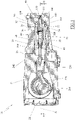
- the volumetric pump 10 has an outer casing 20, inside of which a cylinder jacket 30 is housed which contains a cylinder 35 in which at least one piston 40 slides which has alternative motion, thanks to a thrust crank mechanism associated with the piston itself.
- the cylinder 35 may be accommodated within the cylinder jacket 30, so that its axis A is parallel to or preferably coincides with the axis of the cylinder jacket 30 itself.
- the cylinder jacket 30 comprises a first axial end 36, which may be defined by a flat surface oriented orthogonally with respect to the axis of the cylinder 35.
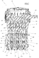
- This first axial end 36 of the cylinder jacket 30 is closed by a cylinder head 50, in which at least one low pressure fluid inlet manifold 60 and at least one low pressure fluid delivery manifold 70 are obtained ( Fig.2 ), a low pressure sealing gasket 55 being interposed between the head 50 and the cylinder jacket 30, which may have an annular shape with an axis parallel or coinciding with the axis A of the cylinder 35 and may be accommodated in a seat 56 obtained on a surface of the axial end 36.
- an axial end 25 of the casing 20 is coplanar with the axial end 36 of the cylinder jacket 30 and the head 50 rests against both axial ends 25 and 36 and is made integral with the outer casing 20 by means of customary fixing screws, not illustrated.
- the alternative piston 40 together with the corresponding cylinder 35 and cylinder head 50, defines a respective variable volume compression chamber 99.
- the positive displacement pump 10 within the casing 20 comprises a plurality of identical cylinders 35, in this case three, spaced apart and parallel to each other in which a respective piston 40 slides. This does not preclude other embodiments of the invention from comprising a different number of cylinders.
- the cylinder head 50 has at the cylinder 35 a seat 90 for receiving a pressure fluid delivery valve 100, which comprises a valve body 110 and a shutter 111 acting on a valve seat 112 of the valve body 110.
- the seat 90 has at least one first cavity 95 having a circular section, for example cylindrical, whose axis is parallel to or coincides with the axis A of the cylinder 35 and/or the cylinder jacket 30.
- the cavity 95 has an opening 96 at a contact surface between the cylinder head 50 and the first axial end 36 of the cylinder jacket 30.
- the diameter of the opening 96 is smaller than the outer diameter of the cylinder jacket 30, so that between the diameter of the cavity 95, at the opening 96, and the outer diameter of the cylinder jacket 30, there is a seat 56 for accommodating the low-pressure gasket 55, as can be seen in Figs. 3 and 4 .
- the valve body 110 of the delivery valve 100 comprises a first portion 120, which is fitted inside the cylinder jacket 30 with the interposition of a high-pressure gasket 130, and a central portion 115 accommodated inside the cavity 95.
- the first portion 120 has two annular bands 121 and 122, of which the first annular band 121 functions as a seat for the sealing gasket 130, while the function of the second annular band 122, located at the free axial end of the first portion 120 will be clarified below.
- the valve body 110 has a high pressure fluid delivery duct 140, preferably coaxial with the longitudinal axis A of the cylinder 35, and at least one low pressure fluid inlet duct 150.
- the inlet duct 150 has an opening 151 at the compression chamber 99, and an opening 152 that flows into a side wall 116 of the central portion 115 of the valve body 110.
- the first opening 151 is located on a surface of the free end of the first portion 120 of the valve body 110 at the compression chamber 99.
- valve body has eight low-pressure fluid inlet ducts 150 equally angularly equidistant from each other, visible two by two in the figures.
- the central portion 115 of the valve body 110 has a maximum outer diameter greater than the inner diameter of the cylinder jacket 30 and less than the diameter of the first cavity 95, such that a low pressure fluid supply chamber 160 is delimited at least by the side wall 116 of the central portion 115 of the valve body 110, by a portion of the inner surface of the first cavity 95 and by a portion of the surface of the axial end 36 of the cylinder jacket 30, said supply chamber 160 being in communication with each low pressure fluid inlet duct 150 and fluid inlet manifold 60.
- the high-pressure fluid flowing from the high-pressure gasket 130 pours into the low-pressure fluid supply chamber 160, reducing wear on the low-pressure gasket 55 and thereby increasing its service life. This makes it possible to reduce the maintenance work required to restore the low-pressure gasket 55.
- At least one annular groove 127 is made to increase the volume of the feed chamber 160.
- the seat 90 comprises a second cavity 97, coaxial with the first cavity 95 and derived from the back wall of the first cavity 95, opposed to the opening 96, and accommodates a second portion 118 of the valve body 110.
- the second portion 118 is distal to and opposite the first portion 120.
- the free end of the second portion 118 comprises the valve seat 112 on which the shutter 111 of the delivery valve 100 acts.
- the shutter 111 is accommodated and adapted to translate inside a support cage 113 which is inserted in an annular groove present at the free end of the second portion 118 of the valve body 110, a high-pressure gasket 119 of the usual type being interposed between the cage and a wall of said groove.
- the shutter 111 is normally held against the valve seat 112 by a compression spring 114 inserted inside the cage 113.
- the cylinder 35 is associated with a low-pressure fluid inlet valve 80 comprising a shutter 81 to obstruct the openings 151 of the inlet ducts 150.
- the shutter 81 is annular in shape and has a central hole at the delivery duct 140.
- the cylinder 35 has two respective opposite axial ends shaped like tangs 38 and 39.
- the tang 38 with which the inlet valve 80 is associated, has an outer diameter smaller than the maximum outer diameter of the cylinder and is provided with 4 through-holes 380, angularly equidistant from each other, for the inlet of the fluid into the chamber 100.
- the supply valve 80 is inserted in the annular space between the outer surface of the shank 38 and an inner surface of the cylinder jacket 30 in the annular space between the outer surface of the shank 38 and an inner surface of the cylinder jacket 30 inserted.
- the supply valve 80 comprises a cup-shaped body 82 ( Fig,4 ), which is inserted on the tang 38 and which has a hole on the bottom wall for the passage of the tang 38 itself.
- the open end of the cup-shaped body 82 is accommodated in the annular space defined between the inner surface of the cylinder jacket 30 and the annular band 122 of the first portion 120 of the valve body 110 and has the function of holding the high pressure gasket 130 in place.
- a compression spring 83 is inserted to which the shutter 81 is constrained, which is therefore normally maintained in a closed position, i.e. against the openings 151 of the delivery duct 150.
- the tang 39 ( Fig.4 ) of the cylinder 35 is inserted in a perforated cavity 300 of the cylinder jacket 30 in which a bushing 180 of the piston 40 is housed, a sealing gasket 181 being interposed between the bushing 180 and the tang 39.
- the outer casing 20 has a second axial end 26 to which a crankcase 27 is fixed, closed at the opposite end by a cover 28.
- the crankcase 27 houses a crankshaft 200 and three connecting rods 220, each of which is articulated both to the crankshaft 200 and to a rear shaft 230 fixed to a respective piston 40, in such a way as to form a thrust crank mechanism (of the connecting rod-crank type) adapted to transform the rotational movement of the crankshaft 200 into an alternative movement of the piston 40 along the direction defined by its longitudinal axis A.
- crankshaft 200 The rotation of the crankshaft 200 is driven by a motor (not illustrated) located outside the crankcase 27.
- a perforated clamping body 240 to allow the passage of the piston 40 and which has a seat for accommodating a lip gasket 250 whose function is to prevent any water leakage from the high pressure gasket 181.
Landscapes
- Engineering & Computer Science (AREA)
- Mechanical Engineering (AREA)
- General Engineering & Computer Science (AREA)
- Details Of Reciprocating Pumps (AREA)
- Reciprocating Pumps (AREA)
Applications Claiming Priority (1)
| Application Number | Priority Date | Filing Date | Title |
|---|---|---|---|
| IT102021000006824A IT202100006824A1 (it) | 2021-03-22 | 2021-03-22 | Pompa volumetrica a pistoni ad alta pressione |
Publications (2)
| Publication Number | Publication Date |
|---|---|
| EP4063653A1 true EP4063653A1 (de) | 2022-09-28 |
| EP4063653B1 EP4063653B1 (de) | 2024-07-17 |
Family
ID=76601542
Family Applications (1)
| Application Number | Title | Priority Date | Filing Date |
|---|---|---|---|
| EP22160445.7A Active EP4063653B1 (de) | 2021-03-22 | 2022-03-07 | Volumetrische hochdruck-kolbenpumpe |
Country Status (4)
| Country | Link |
|---|---|
| EP (1) | EP4063653B1 (de) |
| CN (1) | CN115163479A (de) |
| DK (1) | DK4063653T3 (de) |
| IT (1) | IT202100006824A1 (de) |
Cited By (2)
| Publication number | Priority date | Publication date | Assignee | Title |
|---|---|---|---|---|
| IT202200026238A1 (it) * | 2022-12-21 | 2024-06-21 | Mixtron S R L | Gruppo valvola di mandata e aspirazione automatico e pompa dotata di detto gruppo valvola |
| CN120444213A (zh) * | 2025-07-11 | 2025-08-08 | 中国矿业大学 | 一种适用于隧/巷道注浆的脉冲泵和注浆系统 |
Citations (4)
| Publication number | Priority date | Publication date | Assignee | Title |
|---|---|---|---|---|
| DE1162855B (de) * | 1961-06-19 | 1964-02-13 | Burckhardt Ag Maschf | Hochdruck-Kolbenpumpe fuer tiefkalte Fluessigkeiten |
| US4412792A (en) * | 1981-01-21 | 1983-11-01 | The Oilgear Company | Intensifier pump with integrated check valve |
| WO1995027142A1 (en) * | 1994-04-04 | 1995-10-12 | Reynolds Metals Company | High-pressure liquid pump and flow control valve |
| EP3578811A1 (de) * | 2018-06-08 | 2019-12-11 | Annovi Reverberi S.p.A. | Volumetrische kolbenpumpe |
Family Cites Families (1)
| Publication number | Priority date | Publication date | Assignee | Title |
|---|---|---|---|---|
| AU2012100687A4 (en) * | 2011-05-20 | 2012-06-14 | Techtronic Outdoor Products Technology Limited | Cylinder head for a pump |
-
2021
- 2021-03-22 IT IT102021000006824A patent/IT202100006824A1/it unknown
-
2022
- 2022-03-07 DK DK22160445.7T patent/DK4063653T3/da active
- 2022-03-07 EP EP22160445.7A patent/EP4063653B1/de active Active
- 2022-03-21 CN CN202210282231.0A patent/CN115163479A/zh active Pending
Patent Citations (4)
| Publication number | Priority date | Publication date | Assignee | Title |
|---|---|---|---|---|
| DE1162855B (de) * | 1961-06-19 | 1964-02-13 | Burckhardt Ag Maschf | Hochdruck-Kolbenpumpe fuer tiefkalte Fluessigkeiten |
| US4412792A (en) * | 1981-01-21 | 1983-11-01 | The Oilgear Company | Intensifier pump with integrated check valve |
| WO1995027142A1 (en) * | 1994-04-04 | 1995-10-12 | Reynolds Metals Company | High-pressure liquid pump and flow control valve |
| EP3578811A1 (de) * | 2018-06-08 | 2019-12-11 | Annovi Reverberi S.p.A. | Volumetrische kolbenpumpe |
Cited By (3)
| Publication number | Priority date | Publication date | Assignee | Title |
|---|---|---|---|---|
| IT202200026238A1 (it) * | 2022-12-21 | 2024-06-21 | Mixtron S R L | Gruppo valvola di mandata e aspirazione automatico e pompa dotata di detto gruppo valvola |
| WO2024134393A1 (en) * | 2022-12-21 | 2024-06-27 | Mixtron S.R.L. | Automatic delivery and suction valve assembly and pump provided with said valve assembly |
| CN120444213A (zh) * | 2025-07-11 | 2025-08-08 | 中国矿业大学 | 一种适用于隧/巷道注浆的脉冲泵和注浆系统 |
Also Published As
| Publication number | Publication date |
|---|---|
| IT202100006824A1 (it) | 2022-09-22 |
| DK4063653T3 (da) | 2024-10-14 |
| CN115163479A (zh) | 2022-10-11 |
| EP4063653B1 (de) | 2024-07-17 |
Similar Documents
| Publication | Publication Date | Title |
|---|---|---|
| EP2860396B1 (de) | Pumpe | |
| US4184817A (en) | High pressure multi-cylinder pump | |
| US5636975A (en) | Inlet and discharge valve arrangement for a high pressure pump | |
| EP4063653B1 (de) | Volumetrische hochdruck-kolbenpumpe | |
| CN111425368A (zh) | 泵送装置 | |
| US3715174A (en) | Diaphragm pump | |
| EP0011903B1 (de) | Hydraulische Pumpe | |
| US4229011A (en) | Lubrication system for reciprocating plunger compressors | |
| US4392787A (en) | Diaphragm pump | |
| US2716945A (en) | Variable stroke rotary cylinder pump | |
| CN110345371A (zh) | 自润滑泵的喉部密封件 | |
| US11732700B2 (en) | Automatic bidirectional valve and pump provided with said valve | |
| US5624246A (en) | Hydraulic ammonia solution pump | |
| EP3578811B1 (de) | Volumetrische kolbenpumpe | |
| EP4291782B1 (de) | Axialpumpe mit schrägscheibe | |
| US4721444A (en) | Fluid pump incorporating pulsation dampener surrounding its shaft | |
| US4242063A (en) | High pressure multi-cylinder pump | |
| CN115956160A (zh) | 用于输送介质的往复活塞泵 | |
| KR102216489B1 (ko) | 내연 피스톤 기관에 연료를 공급하기 위한 연료 펌프 | |
| GB2309270A (en) | Radial plunger pump | |
| JP2003148326A (ja) | シリンダ装置およびアキシャルピストンポンプ | |
| EP3601778B1 (de) | Kraftstoffpumpe für eine verbrennungskraftmaschine | |
| US20140144131A1 (en) | Energy Efficient Variable Displacement Dosing Pump | |
| US3640647A (en) | Diaphragm pump | |
| CN121986218A (zh) | 用于高压泵的平衡压力密封件 |
Legal Events
| Date | Code | Title | Description |
|---|---|---|---|
| PUAI | Public reference made under article 153(3) epc to a published international application that has entered the european phase |
Free format text: ORIGINAL CODE: 0009012 |
|
| STAA | Information on the status of an ep patent application or granted ep patent |
Free format text: STATUS: THE APPLICATION HAS BEEN PUBLISHED |
|
| AK | Designated contracting states |
Kind code of ref document: A1 Designated state(s): AL AT BE BG CH CY CZ DE DK EE ES FI FR GB GR HR HU IE IS IT LI LT LU LV MC MK MT NL NO PL PT RO RS SE SI SK SM TR |
|
| STAA | Information on the status of an ep patent application or granted ep patent |
Free format text: STATUS: REQUEST FOR EXAMINATION WAS MADE |
|
| 17P | Request for examination filed |
Effective date: 20230316 |
|
| RBV | Designated contracting states (corrected) |
Designated state(s): AL AT BE BG CH CY CZ DE DK EE ES FI FR GB GR HR HU IE IS IT LI LT LU LV MC MK MT NL NO PL PT RO RS SE SI SK SM TR |
|
| P01 | Opt-out of the competence of the unified patent court (upc) registered |
Effective date: 20230513 |
|
| GRAP | Despatch of communication of intention to grant a patent |
Free format text: ORIGINAL CODE: EPIDOSNIGR1 |
|
| STAA | Information on the status of an ep patent application or granted ep patent |
Free format text: STATUS: GRANT OF PATENT IS INTENDED |
|
| RIC1 | Information provided on ipc code assigned before grant |
Ipc: F16K 11/10 20060101ALI20240202BHEP Ipc: F04B 53/16 20060101ALI20240202BHEP Ipc: F04B 53/10 20060101ALI20240202BHEP Ipc: F04B 1/0456 20200101ALI20240202BHEP Ipc: F04B 1/0452 20200101AFI20240202BHEP |
|
| INTG | Intention to grant announced |
Effective date: 20240306 |
|
| GRAS | Grant fee paid |
Free format text: ORIGINAL CODE: EPIDOSNIGR3 |
|
| GRAA | (expected) grant |
Free format text: ORIGINAL CODE: 0009210 |
|
| STAA | Information on the status of an ep patent application or granted ep patent |
Free format text: STATUS: THE PATENT HAS BEEN GRANTED |
|
| AK | Designated contracting states |
Kind code of ref document: B1 Designated state(s): AL AT BE BG CH CY CZ DE DK EE ES FI FR GB GR HR HU IE IS IT LI LT LU LV MC MK MT NL NO PL PT RO RS SE SI SK SM TR |
|
| REG | Reference to a national code |
Ref country code: CH Ref legal event code: EP |
|
| REG | Reference to a national code |
Ref country code: DE Ref legal event code: R096 Ref document number: 602022004542 Country of ref document: DE |
|
| REG | Reference to a national code |
Ref country code: IE Ref legal event code: FG4D |
|
| REG | Reference to a national code |
Ref country code: DK Ref legal event code: T3 Effective date: 20241007 |
|
| REG | Reference to a national code |
Ref country code: LT Ref legal event code: MG9D |
|
| REG | Reference to a national code |
Ref country code: NL Ref legal event code: MP Effective date: 20240717 |
|
| PG25 | Lapsed in a contracting state [announced via postgrant information from national office to epo] |
Ref country code: PT Free format text: LAPSE BECAUSE OF FAILURE TO SUBMIT A TRANSLATION OF THE DESCRIPTION OR TO PAY THE FEE WITHIN THE PRESCRIBED TIME-LIMIT Effective date: 20241118 |
|
| REG | Reference to a national code |
Ref country code: AT Ref legal event code: MK05 Ref document number: 1704370 Country of ref document: AT Kind code of ref document: T Effective date: 20240717 |
|
| PG25 | Lapsed in a contracting state [announced via postgrant information from national office to epo] |
Ref country code: NL Free format text: LAPSE BECAUSE OF FAILURE TO SUBMIT A TRANSLATION OF THE DESCRIPTION OR TO PAY THE FEE WITHIN THE PRESCRIBED TIME-LIMIT Effective date: 20240717 |
|
| PG25 | Lapsed in a contracting state [announced via postgrant information from national office to epo] |
Ref country code: PT Free format text: LAPSE BECAUSE OF FAILURE TO SUBMIT A TRANSLATION OF THE DESCRIPTION OR TO PAY THE FEE WITHIN THE PRESCRIBED TIME-LIMIT Effective date: 20241118 Ref country code: NL Free format text: LAPSE BECAUSE OF FAILURE TO SUBMIT A TRANSLATION OF THE DESCRIPTION OR TO PAY THE FEE WITHIN THE PRESCRIBED TIME-LIMIT Effective date: 20240717 |
|
| PG25 | Lapsed in a contracting state [announced via postgrant information from national office to epo] |
Ref country code: NO Free format text: LAPSE BECAUSE OF FAILURE TO SUBMIT A TRANSLATION OF THE DESCRIPTION OR TO PAY THE FEE WITHIN THE PRESCRIBED TIME-LIMIT Effective date: 20241017 |
|
| PG25 | Lapsed in a contracting state [announced via postgrant information from national office to epo] |
Ref country code: FI Free format text: LAPSE BECAUSE OF FAILURE TO SUBMIT A TRANSLATION OF THE DESCRIPTION OR TO PAY THE FEE WITHIN THE PRESCRIBED TIME-LIMIT Effective date: 20240717 Ref country code: PL Free format text: LAPSE BECAUSE OF FAILURE TO SUBMIT A TRANSLATION OF THE DESCRIPTION OR TO PAY THE FEE WITHIN THE PRESCRIBED TIME-LIMIT Effective date: 20240717 Ref country code: GR Free format text: LAPSE BECAUSE OF FAILURE TO SUBMIT A TRANSLATION OF THE DESCRIPTION OR TO PAY THE FEE WITHIN THE PRESCRIBED TIME-LIMIT Effective date: 20241018 |
|
| PG25 | Lapsed in a contracting state [announced via postgrant information from national office to epo] |
Ref country code: BG Free format text: LAPSE BECAUSE OF FAILURE TO SUBMIT A TRANSLATION OF THE DESCRIPTION OR TO PAY THE FEE WITHIN THE PRESCRIBED TIME-LIMIT Effective date: 20240717 |
|
| PG25 | Lapsed in a contracting state [announced via postgrant information from national office to epo] |
Ref country code: LV Free format text: LAPSE BECAUSE OF FAILURE TO SUBMIT A TRANSLATION OF THE DESCRIPTION OR TO PAY THE FEE WITHIN THE PRESCRIBED TIME-LIMIT Effective date: 20240717 |
|
| PG25 | Lapsed in a contracting state [announced via postgrant information from national office to epo] |
Ref country code: AT Free format text: LAPSE BECAUSE OF FAILURE TO SUBMIT A TRANSLATION OF THE DESCRIPTION OR TO PAY THE FEE WITHIN THE PRESCRIBED TIME-LIMIT Effective date: 20240717 Ref country code: IS Free format text: LAPSE BECAUSE OF FAILURE TO SUBMIT A TRANSLATION OF THE DESCRIPTION OR TO PAY THE FEE WITHIN THE PRESCRIBED TIME-LIMIT Effective date: 20241117 |
|
| PG25 | Lapsed in a contracting state [announced via postgrant information from national office to epo] |
Ref country code: HR Free format text: LAPSE BECAUSE OF FAILURE TO SUBMIT A TRANSLATION OF THE DESCRIPTION OR TO PAY THE FEE WITHIN THE PRESCRIBED TIME-LIMIT Effective date: 20240717 |
|
| PG25 | Lapsed in a contracting state [announced via postgrant information from national office to epo] |
Ref country code: ES Free format text: LAPSE BECAUSE OF FAILURE TO SUBMIT A TRANSLATION OF THE DESCRIPTION OR TO PAY THE FEE WITHIN THE PRESCRIBED TIME-LIMIT Effective date: 20240717 Ref country code: RS Free format text: LAPSE BECAUSE OF FAILURE TO SUBMIT A TRANSLATION OF THE DESCRIPTION OR TO PAY THE FEE WITHIN THE PRESCRIBED TIME-LIMIT Effective date: 20241017 |
|
| PG25 | Lapsed in a contracting state [announced via postgrant information from national office to epo] |
Ref country code: RS Free format text: LAPSE BECAUSE OF FAILURE TO SUBMIT A TRANSLATION OF THE DESCRIPTION OR TO PAY THE FEE WITHIN THE PRESCRIBED TIME-LIMIT Effective date: 20241017 Ref country code: PL Free format text: LAPSE BECAUSE OF FAILURE TO SUBMIT A TRANSLATION OF THE DESCRIPTION OR TO PAY THE FEE WITHIN THE PRESCRIBED TIME-LIMIT Effective date: 20240717 Ref country code: NO Free format text: LAPSE BECAUSE OF FAILURE TO SUBMIT A TRANSLATION OF THE DESCRIPTION OR TO PAY THE FEE WITHIN THE PRESCRIBED TIME-LIMIT Effective date: 20241017 Ref country code: LV Free format text: LAPSE BECAUSE OF FAILURE TO SUBMIT A TRANSLATION OF THE DESCRIPTION OR TO PAY THE FEE WITHIN THE PRESCRIBED TIME-LIMIT Effective date: 20240717 Ref country code: IS Free format text: LAPSE BECAUSE OF FAILURE TO SUBMIT A TRANSLATION OF THE DESCRIPTION OR TO PAY THE FEE WITHIN THE PRESCRIBED TIME-LIMIT Effective date: 20241117 Ref country code: HR Free format text: LAPSE BECAUSE OF FAILURE TO SUBMIT A TRANSLATION OF THE DESCRIPTION OR TO PAY THE FEE WITHIN THE PRESCRIBED TIME-LIMIT Effective date: 20240717 Ref country code: GR Free format text: LAPSE BECAUSE OF FAILURE TO SUBMIT A TRANSLATION OF THE DESCRIPTION OR TO PAY THE FEE WITHIN THE PRESCRIBED TIME-LIMIT Effective date: 20241018 Ref country code: FI Free format text: LAPSE BECAUSE OF FAILURE TO SUBMIT A TRANSLATION OF THE DESCRIPTION OR TO PAY THE FEE WITHIN THE PRESCRIBED TIME-LIMIT Effective date: 20240717 Ref country code: ES Free format text: LAPSE BECAUSE OF FAILURE TO SUBMIT A TRANSLATION OF THE DESCRIPTION OR TO PAY THE FEE WITHIN THE PRESCRIBED TIME-LIMIT Effective date: 20240717 Ref country code: BG Free format text: LAPSE BECAUSE OF FAILURE TO SUBMIT A TRANSLATION OF THE DESCRIPTION OR TO PAY THE FEE WITHIN THE PRESCRIBED TIME-LIMIT Effective date: 20240717 Ref country code: AT Free format text: LAPSE BECAUSE OF FAILURE TO SUBMIT A TRANSLATION OF THE DESCRIPTION OR TO PAY THE FEE WITHIN THE PRESCRIBED TIME-LIMIT Effective date: 20240717 |
|
| PG25 | Lapsed in a contracting state [announced via postgrant information from national office to epo] |
Ref country code: RO Free format text: LAPSE BECAUSE OF FAILURE TO SUBMIT A TRANSLATION OF THE DESCRIPTION OR TO PAY THE FEE WITHIN THE PRESCRIBED TIME-LIMIT Effective date: 20240717 Ref country code: SM Free format text: LAPSE BECAUSE OF FAILURE TO SUBMIT A TRANSLATION OF THE DESCRIPTION OR TO PAY THE FEE WITHIN THE PRESCRIBED TIME-LIMIT Effective date: 20240717 |
|
| REG | Reference to a national code |
Ref country code: DE Ref legal event code: R097 Ref document number: 602022004542 Country of ref document: DE |
|
| PG25 | Lapsed in a contracting state [announced via postgrant information from national office to epo] |
Ref country code: EE Free format text: LAPSE BECAUSE OF FAILURE TO SUBMIT A TRANSLATION OF THE DESCRIPTION OR TO PAY THE FEE WITHIN THE PRESCRIBED TIME-LIMIT Effective date: 20240717 |
|
| PG25 | Lapsed in a contracting state [announced via postgrant information from national office to epo] |
Ref country code: CZ Free format text: LAPSE BECAUSE OF FAILURE TO SUBMIT A TRANSLATION OF THE DESCRIPTION OR TO PAY THE FEE WITHIN THE PRESCRIBED TIME-LIMIT Effective date: 20240717 |
|
| PG25 | Lapsed in a contracting state [announced via postgrant information from national office to epo] |
Ref country code: SK Free format text: LAPSE BECAUSE OF FAILURE TO SUBMIT A TRANSLATION OF THE DESCRIPTION OR TO PAY THE FEE WITHIN THE PRESCRIBED TIME-LIMIT Effective date: 20240717 |
|
| PLBE | No opposition filed within time limit |
Free format text: ORIGINAL CODE: 0009261 |
|
| STAA | Information on the status of an ep patent application or granted ep patent |
Free format text: STATUS: NO OPPOSITION FILED WITHIN TIME LIMIT |
|
| 26N | No opposition filed |
Effective date: 20250422 |
|
| PG25 | Lapsed in a contracting state [announced via postgrant information from national office to epo] |
Ref country code: SE Free format text: LAPSE BECAUSE OF FAILURE TO SUBMIT A TRANSLATION OF THE DESCRIPTION OR TO PAY THE FEE WITHIN THE PRESCRIBED TIME-LIMIT Effective date: 20240717 |
|
| PG25 | Lapsed in a contracting state [announced via postgrant information from national office to epo] |
Ref country code: MC Free format text: LAPSE BECAUSE OF FAILURE TO SUBMIT A TRANSLATION OF THE DESCRIPTION OR TO PAY THE FEE WITHIN THE PRESCRIBED TIME-LIMIT Effective date: 20240717 |
|
| REG | Reference to a national code |
Ref country code: CH Ref legal event code: H13 Free format text: ST27 STATUS EVENT CODE: U-0-0-H10-H13 (AS PROVIDED BY THE NATIONAL OFFICE) Effective date: 20251023 |
|
| PG25 | Lapsed in a contracting state [announced via postgrant information from national office to epo] |
Ref country code: LU Free format text: LAPSE BECAUSE OF NON-PAYMENT OF DUE FEES Effective date: 20250307 |
|
| REG | Reference to a national code |
Ref country code: BE Ref legal event code: MM Effective date: 20250331 |
|
| PG25 | Lapsed in a contracting state [announced via postgrant information from national office to epo] |
Ref country code: FR Free format text: LAPSE BECAUSE OF NON-PAYMENT OF DUE FEES Effective date: 20250331 |
|
| PG25 | Lapsed in a contracting state [announced via postgrant information from national office to epo] |
Ref country code: BE Free format text: LAPSE BECAUSE OF NON-PAYMENT OF DUE FEES Effective date: 20250331 |
|
| PG25 | Lapsed in a contracting state [announced via postgrant information from national office to epo] |
Ref country code: CH Free format text: LAPSE BECAUSE OF NON-PAYMENT OF DUE FEES Effective date: 20250331 |
|
| PG25 | Lapsed in a contracting state [announced via postgrant information from national office to epo] |
Ref country code: IE Free format text: LAPSE BECAUSE OF NON-PAYMENT OF DUE FEES Effective date: 20250307 |
|
| PGFP | Annual fee paid to national office [announced via postgrant information from national office to epo] |
Ref country code: DK Payment date: 20260325 Year of fee payment: 5 Ref country code: DE Payment date: 20260327 Year of fee payment: 5 |
|
| PGFP | Annual fee paid to national office [announced via postgrant information from national office to epo] |
Ref country code: IT Payment date: 20260128 Year of fee payment: 5 |