EP4063667B1 - Lüfter - Google Patents
Lüfter Download PDFInfo
- Publication number
- EP4063667B1 EP4063667B1 EP20890355.9A EP20890355A EP4063667B1 EP 4063667 B1 EP4063667 B1 EP 4063667B1 EP 20890355 A EP20890355 A EP 20890355A EP 4063667 B1 EP4063667 B1 EP 4063667B1
- Authority
- EP
- European Patent Office
- Prior art keywords
- air
- output
- air outlet
- way seat
- nozzle
- Prior art date
- Legal status (The legal status is an assumption and is not a legal conclusion. Google has not performed a legal analysis and makes no representation as to the accuracy of the status listed.)
- Active
Links
Images









Classifications
-
- F—MECHANICAL ENGINEERING; LIGHTING; HEATING; WEAPONS; BLASTING
- F04—POSITIVE - DISPLACEMENT MACHINES FOR LIQUIDS; PUMPS FOR LIQUIDS OR ELASTIC FLUIDS
- F04F—PUMPING OF FLUID BY DIRECT CONTACT OF ANOTHER FLUID OR BY USING INERTIA OF FLUID TO BE PUMPED; SIPHONS
- F04F5/00—Jet pumps, i.e. devices in which flow is induced by pressure drop caused by velocity of another fluid flow
- F04F5/14—Jet pumps, i.e. devices in which flow is induced by pressure drop caused by velocity of another fluid flow the inducing fluid being elastic fluid
- F04F5/16—Jet pumps, i.e. devices in which flow is induced by pressure drop caused by velocity of another fluid flow the inducing fluid being elastic fluid displacing elastic fluids
-
- F—MECHANICAL ENGINEERING; LIGHTING; HEATING; WEAPONS; BLASTING
- F04—POSITIVE - DISPLACEMENT MACHINES FOR LIQUIDS; PUMPS FOR LIQUIDS OR ELASTIC FLUIDS
- F04D—NON-POSITIVE-DISPLACEMENT PUMPS
- F04D17/00—Radial-flow pumps, e.g. centrifugal pumps; Helico-centrifugal pumps
- F04D17/06—Helico-centrifugal pumps
-
- F—MECHANICAL ENGINEERING; LIGHTING; HEATING; WEAPONS; BLASTING
- F04—POSITIVE - DISPLACEMENT MACHINES FOR LIQUIDS; PUMPS FOR LIQUIDS OR ELASTIC FLUIDS
- F04D—NON-POSITIVE-DISPLACEMENT PUMPS
- F04D25/00—Pumping installations or systems
- F04D25/02—Units comprising pumps and their driving means
- F04D25/06—Units comprising pumps and their driving means the pump being electrically driven
- F04D25/0606—Units comprising pumps and their driving means the pump being electrically driven the electric motor being specially adapted for integration in the pump
-
- F—MECHANICAL ENGINEERING; LIGHTING; HEATING; WEAPONS; BLASTING
- F04—POSITIVE - DISPLACEMENT MACHINES FOR LIQUIDS; PUMPS FOR LIQUIDS OR ELASTIC FLUIDS
- F04D—NON-POSITIVE-DISPLACEMENT PUMPS
- F04D25/00—Pumping installations or systems
- F04D25/02—Units comprising pumps and their driving means
- F04D25/08—Units comprising pumps and their driving means the working fluid being air, e.g. for ventilation
-
- F—MECHANICAL ENGINEERING; LIGHTING; HEATING; WEAPONS; BLASTING
- F04—POSITIVE - DISPLACEMENT MACHINES FOR LIQUIDS; PUMPS FOR LIQUIDS OR ELASTIC FLUIDS
- F04D—NON-POSITIVE-DISPLACEMENT PUMPS
- F04D29/00—Details, component parts, or accessories
- F04D29/40—Casings; Connections of working fluid
- F04D29/42—Casings; Connections of working fluid for radial or helico-centrifugal pumps
- F04D29/4206—Casings; Connections of working fluid for radial or helico-centrifugal pumps especially adapted for elastic fluid pumps
- F04D29/4226—Fan casings
- F04D29/4246—Fan casings comprising more than one outlet
-
- F—MECHANICAL ENGINEERING; LIGHTING; HEATING; WEAPONS; BLASTING
- F04—POSITIVE - DISPLACEMENT MACHINES FOR LIQUIDS; PUMPS FOR LIQUIDS OR ELASTIC FLUIDS
- F04D—NON-POSITIVE-DISPLACEMENT PUMPS
- F04D29/00—Details, component parts, or accessories
- F04D29/40—Casings; Connections of working fluid
- F04D29/42—Casings; Connections of working fluid for radial or helico-centrifugal pumps
- F04D29/44—Fluid-guiding means, e.g. diffusers
- F04D29/441—Fluid-guiding means, e.g. diffusers especially adapted for elastic fluid pumps
- F04D29/444—Bladed diffusers
-
- F—MECHANICAL ENGINEERING; LIGHTING; HEATING; WEAPONS; BLASTING
- F04—POSITIVE - DISPLACEMENT MACHINES FOR LIQUIDS; PUMPS FOR LIQUIDS OR ELASTIC FLUIDS
- F04D—NON-POSITIVE-DISPLACEMENT PUMPS
- F04D29/00—Details, component parts, or accessories
- F04D29/66—Combating cavitation, whirls, noise, vibration or the like; Balancing
- F04D29/661—Combating cavitation, whirls, noise, vibration or the like; Balancing especially adapted for elastic fluid pumps
- F04D29/668—Combating cavitation, whirls, noise, vibration or the like; Balancing especially adapted for elastic fluid pumps damping or preventing mechanical vibrations
-
- F—MECHANICAL ENGINEERING; LIGHTING; HEATING; WEAPONS; BLASTING
- F04—POSITIVE - DISPLACEMENT MACHINES FOR LIQUIDS; PUMPS FOR LIQUIDS OR ELASTIC FLUIDS
- F04D—NON-POSITIVE-DISPLACEMENT PUMPS
- F04D29/00—Details, component parts, or accessories
- F04D29/70—Suction grids; Strainers; Dust separation; Cleaning
- F04D29/701—Suction grids; Strainers; Dust separation; Cleaning especially adapted for elastic fluid pumps
- F04D29/703—Suction grids; Strainers; Dust separation; Cleaning especially adapted for elastic fluid pumps specially for fans, e.g. fan guards
Definitions
- the present disclosure relates generally to air adjusting equipment, and more particularly to a fan.
- Air purifiers are small household appliances used to purify indoor air, and they mainly solve indoor air pollution due to decoration or other reasons. Due to the persistence and uncertainty of the release of pollutants in indoor air, purifying indoor air with air purifiers is an internationally recognized method for improving indoor air quality. There are many different technologies and filter media in air purifiers that enable them to provide clean and safe air for the user.
- Commonly used air purification technologies include low-temperature asymmetric plasma air purification technology, adsorption technology, negative ion technology, negative oxygen ion technology, molecular complex technology, nano-TiO2 technology, high efficiency particulate air filter (HEPA) technology, electrostatic dust collection technology, active oxygen technology, etc.; Filter media related technologies mainly include photo catalysts, activated carbon, synthetic fibers, high-efficiency materials of HEPA, etc. The cost of high-quality filters will account for 20% to 30% of the total cost of air purifiers.
- FIG. 1 is a cross-sectional view of a bladeless fan in the prior art.
- most of fan assemblies include an annular nozzle 901, a housing 903, a base 904, a filter 905, a fan motor 906 and a mesh inner tank 907.
- the housing 903 with the air-input mesh is arranged on the base 904, the housing 903 is provided with a filter 905, the filter 905 is provided with a mesh inner tank 907, and the mesh inner tank 907 is provided with first air inlets of the fan motor 906.
- the annular nozzle 901 is located above the housing 903 in the gravity direction, and the air outlet of the fan motor 906 is connected to the nozzle 901.
- the indoor air is filtered by the meshes of the housing 903 and the filter 905 in sequence, then enters the mesh inner tank 907. Then the airflow is drawn by the fan motor 906 in a direction opposite to the gravity direction, conveyed to one end of the annular nozzle 901 in the direction opposite to the gravity direction (upward vertically), and finally emitted by the annular nozzle 901 to everywhere.
- the bladeless fan includes a base, a machine head and a flow dividing portion, a power system is contained in the base, and is used for generating a high-pressure air flow, the machine head includes two air outlet parts, each air outlet part is provided with an air way, each air outlet part is provided with an air outlet which communicates with the corresponding air way, the power system is connected with the two air outlet parts through the flow dividing portion, the flow dividing portion is used for guiding a high-pressure air flow to the two air outlet parts, the flow dividing portion includes a flow dividing portion body, the flow dividing portion body includes an inlet, two outlets and a three-way structure, the three-way structure communicates with the inlet and the two outlets, the two outlets communicate the corresponding air ways of the two air outlet parts, the high-pressure air flow enters the three-way structure from the inlet, the three-way structure is used for dividing the high-pressure air flow entering the three-way structure into two strands of
- the air guiding device of the folding type fan includes a base seat for generating fundamental air flow.
- An impeller and a motor for driving the impeller to rotate are arranged in the base seat.
- a ring-shaped nozzle is provided with an inner channel for receiving the fundamental air flow, and an air outlet seam is arranged in the ring-shaped nozzle.
- the fundamental air flow is emitted from the air outlet seam, and the fundamental air flow emitted by the air outlet seam pulls and absorbs outside air to form air flow
- CN205478589U discloses a bladeless fan and bladeless fan's every single move structure, the bladeless fan includes: a pedestal, a no leaf fan head, the no leaf fan head is rotationally installed on the base and with the base intercommunication, the rotation axis of the no leaf fan head is directional along the horizontal direction.
- the purpose of the present disclosure is to provide a fan to overcome the difficulty in the prior art.
- the fan can change the moving direction of the airflow therein, decrease the entire height and volume of the fan, prolong the filter's life, and reduce the use cost of the fan.
- a fan including:
- the air inlet of the air-output three-way seat is located at a first side of the air-output three-way seat
- the air-splitting wall body is located in the center of a second side of the air-output three-way seat
- the first air outlet and the second air outlet are located at two ends of the second side of the air-output three-way seat.
- the first air outlet and the second air outlet are exposed from two sides of the body, an air-output direction of the first air outlet and an air-output direction of the second air outlet are coaxial, and both perpendicular to an air-input direction of the air inlet of the air-output three-way seat.
- the air-splitting wall body is disposed based on a central axis of the air inlet of the air-output three-way seat, to equally divide the flowing area of the air inlet of the air-output three-way seat.
- the two sides of the air-splitting wall body respectively form a first guiding slope and a second guiding slope symmetric to each other, the first guiding slope guides a part of the airflow passing through the air inlet of the air-output three-way seat to the first air outlet, the second guiding slope guides a part of the airflow passing through the air inlet of the air-output three-way seat to the second air outlet.
- an inner wall of the air-output three-way seat is provided with a plurality of air-guiding pieces extending from the air inlet of the air-output three-way seat to the first air outlet or the second air outlet, respectively.
- an inner wall of the air-output three-way seat is provided with a plurality of air-guiding pieces extending from the air inlet of the air-output three-way seat to the second side of the air-output three-way seat, respectively.
- an inner wall of the air-output three-way seat is provided with a sunken air-guiding step extending from the first guiding slope to the first air outlet, the closer to the first air outlet, the larger the sunken distance of the sunken air-guiding step is;
- the inner wall of the air-output three-way seat is provided with a sunken air-guiding step extending from the second guiding slope to the second air outlet, the closer to the second air outlet, the larger the sunken distance of the sunken air-guiding step is.
- projections at two ends of the air-splitting wall body extend to the air inlet of the air-output three-way seat in the second direction, respectively, to form a U-shaped and plate-shaped air-splitting wall.
- the fan of the present disclosure can change the moving direction of airflow therein, decrease the entire volume and reduce the use cost of the fan.
- FIG. 2 is a schematic view of an inner air passage of a fan according to an embodiment of the present disclosure.
- FIG. 3 is a cross-sectional view along A-A direction in FIG. 2 .
- the fan of the embodiment includes a body 10 for generating an airflow and a nozzle 7.
- the body 10 at least includes a top cover 11, a filter 2, an air-input shroud 3 having air inlets, a fan motor unit 5 for generating the airflow, an outer housing 8 having air outlets and a nozzle 7.
- a first side 8A (shown in FIG. 17 ) of the outer housing 8 is provided with air-input holes 81.
- the filter 2 is located at a position, corresponding to the air-input holes 81, on an inner side of outer housing 8.
- the filter 2 is located upstream from the air-input shroud 3, and the filter 2 surrounds the air-input shroud 3.
- the air-input shroud 3 is located at the air inlets of the fan motor unit 5.
- the fan motor unit 5 makes the airflow pass through the body in a first direction W, wherein the first direction W is the gravity direction.
- the nozzle 7 is connected to the air outlet to receive the airflow from the body 10 and emit the airflow outward. Therefore, the airflow enters the nozzle 7 and is emitted out of the nozzle 7 at least after flowing in a second direction X opposite the first direction W.
- the second direction X is opposite to the gravity direction.
- the air inlets of the body 10 are provided on the air-input shroud 3 located in an upper portion of the body 10 in the gravity direction.
- the air outlets of the body 10 are located in a lower portion of a second side 8B (shown in FIG. 17 ) of the outer housing 8 of the body 10 in the gravity direction.
- the fan motor unit 5 is located in an area between the air inlets of the body 10 and the air outlets of the body 10.
- the nozzle 7 has at least one air-output passage extending in a direction parallel to the first direction W, the airflow passes through the air-output passage in the second direction X.
- the air passage of the fan provided by the present disclosure is designed completely different from the air passage in the prior art, the drawing direction of the fan motor unit 5 is inverted, the airflow is drawn from the upper portion of the body 10, passes through the fan motor unit 5 from top to bottom, then enters the nozzle 7 from the lower portion of the body 10. After the airflow flows through the nozzle 7 from bottom to top, the airflow is emitted outward from the air outlets 71 at different heights.
- the position of the fan motor unit 5 overlaps the position of the nozzle 7 in the first direction, so the entire height of the fan is decreased, the free space in the center of the nozzle 7 is fully utilized.
- the nozzle 7 of the present disclosure can be much bigger than the nozzle in the prior art, so the air supplying capability is greatly enhanced.
- the nozzle 7 can be a tubular member extending in a perpendicular direction and located at one side of the body 10, a lower section of the tubular member can be rotatably connected to an opening of the body 10.
- the nozzle 7 and the fan motor unit 5 can be arranged in parallel in a first direction W (or a second diction X).
- a projection of the nozzle 7 on a vertical plane at least partially overlaps a projection of the fan motor unit 5 on the same vertical plane. Therefore, the air outlets 71 of the nozzle 7 can be provided at the same horizontal height as the fan motor unit 5, or even lower than the horizontal height of the fan motor unit 5.
- the air passage is improved, to change the long flowing distance of the airflow when the airflow passes through the fan motor unit and the nozzle in sequence along a single direction to at least two short flowing distances having opposite directions. The two short flowing distances can be parallel to each other.
- the industrial technical barriers that the fan motor unit and the nozzle must be arranged in sequence in the height direction are broken.
- the entire height of the fan is largely decreased, the center of the gravity of the product is lowered, and the stability of the product in a standing state is increased.
- the air inlets of the body at an upper position won't draw the dust from the ground during drawing air, the usage load of the filter is reduced, to reduce the replacement of the filter, and reduce the use cost of the bladeless fan.
- the air outlets of the fan motor unit 5 are connected to two air-guiding passages, and the two air-guiding passages are respectively connected to openings on two sides of the body 10.
- the nozzle 7 has a nozzle body 70 in a shape of half a frame.
- the nozzle body 70 is bridge connected to a first surface of the body 10 facing toward the first direction W. Two ends of the nozzle body 70 are connected to the openings, respectively.
- the body 10 has at least one air-guiding passage, which can change the flowing direction of the airflow.
- the air-guiding passage extends in a third direction Y perpendicular to the first direction W, and respectively connects the air outlets of the fan motor unit 5 to the nozzle 7.
- the fan motor unit 5, the air-guiding passage and the nozzle 7 together form at least one U-shaped combined air passage, but the present disclosure is not limited to this.
- the nozzle body 70 is inverted U-shaped.
- the nozzle body 70 can rotate relative to the body 10 about an axis of the opening of the body 10 as the rotating shaft, so that the fan can output airflow in different directions.
- the airflow flowing along the nozzle body 70 is in a direction inclined relative to the vertical plane, the airflow still has a displacement in the second direction (opposite to the gravity direction) as the airflow enters a deeper portion of the nozzle body 70.
- the nozzle body 70 is provided with at least one air-output hole 71 opened in a fourth direction Z.
- the fourth direction Z is perpendicular to a plane formed by the first direction W and the third direction Y
- the air-output holes 71 of the nozzle body 70 form an inverted U-shaped air passage, the air inlets of the body 10 are located in the scope of the inverted U-shaped air passage.
- the nozzle body 70 has a first state and a second state.
- the first state the nozzle body 70 is bridge connected to the first surface of the body 10 facing toward the first direction W. After the nozzle body 70 rotates about the axis of the opening, the nozzle body 70 enters the second state.
- the second state the nozzle body 70 is away from a projection area of the filter 2 in the second section.
- the filter 2 can have an up and down displacement in the second diction to get in and out of the body 10 without contact with the nozzle body 70.
- a projection of the up and down displacement of the filter 2 in the second direction doesn't overlap a projection of the nozzle body 70 in the second direction when the nozzle body 7 is in the second state, so that the filter 2 can be detached and removed out of the body 10 in the second direction.
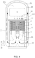
- FIG. 4 is a schematic view of the fan connecting to a functional module.
- the body 10 can be entirely disposed in the central area of the nozzle body 70.
- the central area of the nozzle 70 can be further utilized, to enhance the extended functions, that is, functional extended modules and the body 10 can be provided in the nozzle body 70 together.
- the first surface of the fan facing toward the first direction W and the first surface of the nozzle body 70 together form and surround the accommodating space 75.
- the accommodating space 75 is provided with at least one first connecting terminal 112.
- the fan can further include at least one functional extension member 9 located in the accommodating space 75, and at least one second connecting terminal 91 is connected to the first connecting terminal 112.
- the functional extension member 9 can be at least one of the following: an electronic humidifier; an electronic aromatherapy machine, a LED lamp, an electronic mosquito repellent, an electronic display screen, a charging seat for mobile terminal charging, but the present disclosure is not limited to this.
- the functional extension member 9 can be a jetting member, and the air outlet of the jetting member is exposed to the accommodating space 75. The airflow emitted from the nozzle 7 flows through the air outlet of the jetting member, but the present disclosure is not limited to this.
- Coanda surface is provided at the air outlets arranged on the nozzle 7.
- An air passage is formed from the first side of the nozzle body 70 to a second side of the nozzle body 70 through the accommodating space 75 in the nozzle body 70 with the function of the Coanda surface.
- the air passage conveys a part of the air at one side of the nozzle body 70 to the air output side of the nozzle body 70.
- the air outlet of the jetting member is located in the scope of the air passage formed at the air outlets of the nozzle 7.
- the part of the air flowing through the nozzle body 70 flows through the air outlet of the jetting member, and the functional air emitted by the jetting member is mixed to the airflow emitted from the fan.
- the functional extension member 9 is an electronic humidifier, the airflow emitted from the nozzle 7 flows through the air outlet of the electronic humidifier.
- the inner periphery of the nozzle 7 is provided with a plurality of air outlets opened toward the same side, the air outlets are provided with Coanda surface, to move a part of the air at one side of the nozzle body 70 to the air outlet side of the nozzle body 70, the part of the air passes through the air outlet of the electronic humidifier after passing through the nozzle body 70, to make the airflow emitted by the fan entirely moister. Therefore, the functions of the electronic humidifier and the fan are combined to enhance the humidify effect of the fan.
- the functional extension member 9 can be an electronic aromatherapy machine, the airflow emitted by the nozzle 7 passes through the air outlet of the electronic aromatherapy machine.
- the air outlets having the Coanda surface can also be used to combine the functions of the electronic aromatherapy machine and the fan, to improve the smell in the room, and will not be described in detail.
- the shape of the nozzle body 70 not only a channel for replacing the filter without moving the nozzle body 70 is provided, but also more functional air from the jetting member can be mixed to the airflow emitted from the fan with the help of the continuous Coanda surface formed at the circumferentially arranged air outlets, to combine different functions.
- FIG. 5 is a stereogram of the fan according to the embodiment of the present disclosure.
- FIG. 6 is a cross-sectional view along B-B direction in FIG. 5 .
- FIG. 7 is a cross-sectional view along C-C direction in FIG. 5 .
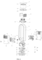
- FIG. 8 is an exploded view of the fan according to the embodiment of the present disclosure.
- the body of the fan includes the base 6, the fan motor unit 5 for generating the airflow, an air-input support 14, the air-input shroud 3 having the air inlets, the filter 2 and the top cover 11 arranged from bottom to top in the second direction X.
- the base 6 includes a power-box upper cover 61, a power supply board 62, a rotating synchronous motor 63, a rotating support 64, a base 65 and a base cover 66.
- the rotation of the rotating synchronous motor 63 can drive the components located above and supported by the power-box upper cover 61, that is, the fan motor unit 5, the air-input shroud 3 and the nozzle 7 etc., to rotate horizontally without replacing their positions.
- Two inner housings 4 capable of being aligned and engaged with each other are engaged together at two sides of the fan motor unit 5 and the base 6. After the inner housings 4 are engaged and screwed together, the fan motor unit 5 is limited at a position above the base 6.
- the sidewall on each end of each inner housing 4 is provided with a first catch 43, a screw hole 42 and a semicircle limiting slot 41 exposing an opening, the semicircle limiting slots 41 form an annular slot after the two inner housings are engaged together.
- the inner sides on two ends of the nozzle body 70 are provided with a first air inlet 72 and a second air inlet 73, respectively. The first air inlet 72 and the second air inlet 73 are connected to one opening, respectively.
- Two outer housings 8 capable of being aligned and engaged with each other are engaged together at the outer periphery of the inner housings 4.
- the outer housings 8 covers the air-input shroud 3 and the fan motor unit 5.
- An area corresponding to the air-input shroud 3 of each outer housing 8 is provided with a plurality of air inlets 81 arranged in a mesh shape.
- the sidewall on each end of each outer housing 8 is provided with a second catch 84, a semicircle splicing portion 82 and a screw hole 83.
- Each second catch 84 of the outer housing 8 is engaged with one first catch 43 of the inner housing 4.
- the lower surfaces of two side supporting frames 13 are connected to the air-input support 14.
- the upper surfaces of the side supporting frames 13 and the screw holes 83 on an upper end of the engaged outer housings 8 are connected through a screw hole 122 on an annular connecting frame 12.
- the inner side of the annular connecting frame 12 is provided with a positioning clamping slot 121.
- the height of the outer housing 8 is larger than the height of the fan motor unit 5.
- a space for accommodating the filter 2 and the air-input shroud 3 are provided between the two side supporting frames 13 above the engaged outer housings 8.
- a plurality of connecting columns 141 are provided on the lower surface of the air-input support 14.
- a plurality of connecting slots 523 are provided at an outer periphery of the fan motor unit 5.
- the connecting columns 141 are inserted in the connecting slots 523, the air-input shroud 3 is connected to an upper surface of the air-input support 14, so that the air-input shroud 3 can be connected to the air inlets of the fan motor unit 5 through the air-input support 14.
- the filter 2 surrounds the air-input shroud 3.
- the filter 2 is disposed upstream from the air inlets of the air-input shroud 3.
- the filter 2 is a tubular air filter 23 (shown in FIG. 20 ), a first side of the tubular air filter 23 is provided with a first annular supporting frame 22 (shown in FIG. 20 ) for fixing a first annular sealing member 21 (shown in FIG. 20 ), the lower surface of the top cover 11 is provided with an inserting slot 56, and the inserting slot 56 can be detachably engaged with the first annular supporting frame 22.
- the lower surface of the top cover 11 is provided with a positioning catch 111, which is detachably engaged in a rotation way with the positioning clamping slot 121 of the annular connecting frame 12.
- the top cover 11 and the air-input support 14 clamp the upper end surface and lower end surface of the filter 2.
- a second side of the tubular air filter 23 is provided with a second annular supporting frame 24 (shown in FIG. 29) for fixing a second annular sealing member 25 (shown in FIG. 20 ).
- the second annular supporting frame 24 is connected to the air-input support 14.
- the first side of the tubular air filter 23 is sealed with the top cover 11 through the first annular sealing member 21.
- the second side of the tubular air filter 23 is sealed with the air-input support 14 through the second annular sealing member 25.
- the first annular sealing member 21 and the second annular sealing member 25 are preferably made of memory sponge.
- the medium of the tubular air filter 23 can be made of existing air filter materials or air filter materials to be invented in the future, the present disclosure is not limited to this.
- FIG. 9 is an exploded view of a part of the fan according to the embodiment of the present disclosure.
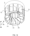
- FIG. 10 is a stereogram of the air inlets of the fan according to the embodiment of the present disclosure.
- FIG. 11 is a schematic view of an air inlet of the fan according to the embodiment of the present disclosure.
- FIG. 12 is a cross-sectional view along D-D direction in FIG. 11 .
- the body 10 of the fan provided by the embodiment is provided with the air-input shroud 3 having air inlets.
- the air-input shroud 3 is disposed downstream from the filter 2, and located in an annular area defined by the filter 2, to make the airflow filtered by the filter 2 enter the fan motor unit 5 through the air-input shroud 3.
- the air-input shroud 3 is located upstream from the air inlets of the fan motor unit 5.
- the air-input shroud 3 can spoil the airflow entering the fan motor unit 5 to reduce noise.
- a plurality of wave-shaped spoilers 32 are provided at an outer periphery of the air-input shroud 3 in the first direction W.
- the wave-shaped spoilers 32 are arranged in circumferential direction of the air-input shroud 3 and at intervals.
- the wave-shaped spoilers 32 extend from the outer periphery toward the center of the air-input shroud 3.
- Air-input passages 33 are formed in the intervals between adjacent wave-shaped spoilers 32.
- the wave-shaped spoilers 32 can divide the airflow drawn in to a plurality of airflows for the first time, to achieve the effect of silencing and noise reduction.
- the inner portion of the air-input shroud 3 is hollow to form a vortex passage 34, a first end of the vortex passage 34 is connected to the air-input passages 33 in a circumferential direction perpendicular to the first direction W, a second end of the vortex passage 34 is connected to the air inlets of the fan motor unit 5 in a second direction X, to reduce noises further.
- the two ends of the air-input passage 33 are provided with air inlets 31 exposed at the outer periphery of the air-input shroud 3 and a narrow slot connected to the vortex passage 34, to reduce the noise further.
- the closer to the vortex passage 34 the smaller the flow area of the air-input passages 33 are, and the closer to the air inlets 31, the larger the flow area of the air-input passages 33 are, to further reduce the noise.
- a rotatable impeller 53 is provided in the fan motor unit 5.
- the protruding direction of the wave shape of each wave-shaped spoiler 32 is the same with a rotation direction of the impeller 53.
- the angles of the air-input passages 33 entering the vortex passage 34 are different from each other, to further reduce the noise.
- a side of each wave-shaped spoilers 32 facing toward the air inlets of the fan motor assembly 5 is provided with a concave arc notch 35, to elongate the distance between the drawn air and the impeller, which also has the effect of reducing the noise.
- FIG. 13 is a stereogram of a fan motor unit of the fan according to the embodiment of the present disclosure.
- FIG. 14 is a cross-sectional view along E-E direction in FIG. 13 .
- FIG. 15 is an exploded view of the fan motor unit of the fan according to the embodiment of the present disclosure.
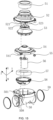
- FIG. 16 is a stereogram of an air-output three-way seat of the fan motor unit of the fan according to the embodiment of the present disclosure. As shown in FIGS.
- the fan motor unit 5 of the fan provided by the embodiment includes: an air-guiding opening shroud 51, an air-guiding shroud 52, the impeller 53, a motor support 54, a motor 56, a motor shroud 58 and an air-output three-way seat 50 assembled in sequence in the first direction W.
- the air-guiding opening shroud 51 seals and connects the vortex passage 34 of the air-input shroud 3 to the air-guiding shroud 52.
- the outer periphery surrounding the air-output three-way seat 50 is provided with a plurality of first positioning seat 501 and a plurality of first screw lugs 508.
- the motor 56 is located between the upper surface of the motor support 54 and the air-output three-way seat 50.
- a plurality of second positioning seat 541 surround the outer periphery of the air-guiding shroud 52.
- the air-output three-way seat 50 is screwed to the air-guiding shroud 52. After each second positioning seat 541 of the motor support 54 is connected to one first positioning seat 501 and one third positioning seat 521 through a flexible connecting piece, the second positioning seat 541 is clamped and limited between the first positioning seat 501 and the third positioning seat 521.
- the motor support 54 is not fixed, but limited between the air-guiding shroud 52 and the air-output three-way seat 5- by the flexible connecting pieces at a same horizontal plane. That is to say, the motor support 54 is suspended between the air-guiding shroud 52 and the air-output three-way seat 50.
- the flexible connecting piece and each positioning seat together form a vibration absorber, so that the motor support 54 won't contact with the air-guiding shroud 52 and the air-output three-way seat 50 during vibration.
- the vibration is transmitted by the contacting points of the vibration absorber, to largely reduce the noise and keep the stability of the fan.
- the top surface of the positioning vibration-damping pad 55 can be a flat surface, to transform the upward vibration generated by the dynamical system to a planar motion, to balance the vibration.
- the lower portion of the positioning vibration-damping pad 55 can be in a conical shape, and the bump of the conical shape contacts with other surfaces, to reduce the contact area and achieve the effect of reducing vibration.
- the center of the positioning vibration-damping pad 55 has a hollow blind hole. Therefore, the positioning vibration-damping pad 55 can be elastically deformed based on the central blind hole when the dynamical system generates vibration, to reduce the vibration. After the blind hole is assembled to the upper support, a sealed hollow hole is formed, to keep the air in the blind hole, so that the positioning vibration-damping pad can return quickly from its elastic deformation under the function of air pressure during vibration.
- the first positioning seats 501, the second positioning seats 541 and the third positioning seats 521 are provided with coaxial through holes, respectively.
- Each flexible connecting piece is a positioning vibration-damping pad 55 in a nail shape.
- the positioning vibration-damping pad 55 passes through and clamps the through holes of the first positioning seat 501, the second positioning seat 541 and the third positioning seat 521.
- the positioning vibration-damping pad 55 includes a rod portion, and an outward-expansion conical platform and an outward-expansion shoulder platform located at two ends of the rod portion, a maximum diameter of the outward-expansion conical platform and a maximum diameter of the outward-expansion shoulder platform are both larger than a diameter of the rod portion.
- the rod portion passes through the through holes of the first positioning seat 501, the second positioning seat 541 and the third positioning seat 521, to clamp the first positioning seat 501, the second positioning seat 541 and the third positioning seat 521 between the outward-expansion conical platform and the outward-expansion shoulder platform.
- the positioning vibration-damping pad 55 is provided with a hollow blind hole in the first direction W and along an axial direction.
- the hollow blind hole at least extends from the outward-expansion conical platform to the rod portion, or the hollow blind hole at least extends from the outward-expansion conical platform to the outward-expansion shoulder platform.
- an annular motor silencing cotton 57 surrounding the outer periphery of the motor 56 is provided between the motor support 54 and the air-output three-way seat 50. The noise caused for the high-speed rotation of the motor and the impeller is further reduced.
- the air-output three-way seat 50 includes an air inlet 507 at an air-output side of the impeller, a first air outlet 504 connected to the nozzle 7, a second air outlet 505 connected to the nozzle 7, and an air-splitting wall body 502.
- the air-splitting wall body 502 is used for splitting the airflow passing through the air inlet 507 and guiding the airflow to the first air outlet 504 and the second air outlet 505.
- the two ends of the nozzle body 70 are connected to the first air outlet 504 and the second air outlet 505, respectively.
- the air inlet 507 is located at a first side of the air-output three-way seat 50, the air-splitting wall body 502 is located in the center of a second ide of the air-output three-way seat 50.
- the first air outlet 504 and the second air outlet 505 are located at two ends of the second side of the air-output three-way seat 50.
- the first air outlet 504 and the second air outlet 505 are exposed out of the two sides of the body 10.
- the air-output direction of the first air outlet 504 and the air-output direction of the second air outlet 505 are coaxial, and both perpendicular to the air-input direction of the air inlet 507.
- the two sides of the air-splitting wall body 502 respectively form a first guiding slope and a second guiding slope symmetric to each other.
- the first guiding slope guides a part of the airflow passing through the air inlet 507 to the first air outlet 504, the second guiding slope guides a part of the airflow passing through the air inlet 507 to the second air outlet 505.
- the projections at two ends of the air-splitting wall body 502 extend to the air inlet 507 in the second direction X, respectively, to form a U-shaped and plate-shaped air-splitting wall. Therefore, the airflow passing through the air inlet 507 can be split while reducing the noise.
- the air-splitting wall body 502 is disposed based on a central axis of the air inlet 507, to equally divide the flowing area of the air inlet 507.
- the inner wall of the air-output three-way seat 50 is provided with a plurality of air-guiding pieces 506 extending from the air inlet 507 to the second side of the air-output three-way seat 50, respectively, but the present disclosure is not limited to this.
- the inner wall of the air-output three-way seat 50 is provided with a sunken air-guiding step extending from the first guiding slope to the first air outlet 504. The closer to the first air outlet 504, the larger the sunken distance of the sunken air-guiding step is.
- the inner wall of the air-output three-way seat 50 is provided with a sunken air-guiding step extending from the second guiding slope to the second air outlet 505.
- the air-output three-way seat 50 integrates the air-guiding function and the air-splitting function together, thereby largely reducing the height of the fan motor assembly 5, and further decreasing the total height and volume of the entire fan.
- the inner wall of the air-output three-way seat 50 is provided with a plurality of air-guiding pieces extending from the air inlet 507 to the first air outlet 504 or the second air outlet 505, respectively, and the present disclosure is not limited to this.
- the air inlet 507 is a mouth of an annular tube, a distance between the mouth of the annular tube and the first air outlet 504 or the second air outlet 505 in the first direction W is d, a diameter of the first air outlet 504 and the second air outlet 505 is h, a ratio d/h ranges from 2.0 to 3.5.
- the airflow generated from impeller 53 enters the air inlet 507 of the air-output three-way seat 50, the airflow will turn the flowing direction at an angle of at least 90° in a very short distance. If the ratio d/h is too small, the air pressure of the airflow will be decreased, the air-output will be reduced, and the air supplying distance will be shortened. If the ratio d/h is too big, vortex negative pressure will be generated, turbulence will be formed and thereby causing a lot of noise.
- the range of the ratio d/h is one of the following ranges: 2.1-3.4, 2.2-3.3, 2.3-3.2, 2.4-3.1, 2.5-3.0, 2.6-2.9, 2.7-2.8.
- the ratio d/h is 2.7.
- FIGS. 17-20 schematically show the mounting process of the fan according to the embodiment of the present disclosure.
- the mounting process of the fan provided by the embodiment is: firstly, the air-input shroud 3, the air-input support 14, the fan motor unit 5 and the base 6 are connected through the first inner housing 4.
- the nozzle 7 having two annular shoulder platforms 74 at two ends is inserted in a horizontal direction to the semicircle limiting slot 41 exposed from the inner housing 4. Therefore, the first air inlet 72 and the second air inlet 73 of the annular shoulder platforms 74 are respectively connected to the first air outlet 504 and the second air outlet 505 of the air-output three-way seat 50 of the fan motor unit 5, and sealed through a sealing ring 59.
- the second inner housing 4 and the first inner housing 4 are engaged and screwed through the screw hole 42, to clamp the annular shoulder platforms 74 in the annular slots formed by the assembly of the two semicircle limiting slots, so that the nozzle 7 can rotate based on the annular slot.
- the two outer housings 8 are snap-fit at the outer periphery of the inner housing 4, the side supporting frame 13 is mounted, then the upper end of the side supporting frame 13 and the upper end of the outer housing 8 are screwed together through the annular connecting frame 12.
- the filter 2 is put in the space between the inner wall of the outer housing 8 and the outer periphery of the air-input shroud 3.
- the filter 2 is sealed and clamped between the top cover 11 and the air-input support frame 14 through the rotating locking between the top cover 11 and the annular connecting frame 12.
- the mounting way of the present disclosure is different from the existing way of sleeving the nozzle 7 on the body in a vertical direction.
- the mounting way of the present disclosure is benefit for the sealing of the air passage, and reduces the mounting difficulty.
- the purpose of the present disclosure is to provide a fan, which can change the moving direction of the airflow, the entire volume of the fan is decreased, and the use cost is reduced.
Landscapes
- Engineering & Computer Science (AREA)
- Mechanical Engineering (AREA)
- General Engineering & Computer Science (AREA)
- Physics & Mathematics (AREA)
- Fluid Mechanics (AREA)
- Structures Of Non-Positive Displacement Pumps (AREA)
Claims (9)
- Ventilator, umfassend:ein Gehäuse (10), das mindestens einen Lufteintritt, mindestens einen Luftaustritt und eine Ventilatormotoreinheit (5) zum Erzeugen eines Luftstroms umfasst, wobei die Ventilatormotoreinheit (5) ein Laufrad (53), einen Motor (56) und ein Luftauslass-Dreiwegestück umfasst; undeine Düse (7), die mit dem Luftaustritt des Gehäuses (10) verbunden ist, wobei die Düse (7) konfiguriert ist, um den Luftstrom vom Gehäuse (10) zu empfangen und den Luftstrom auszustoßen, wobei die Düse (7) einen Düsenkörper (70) in Form eines halben Rahmens umfasst;wobei das Luftauslass-Dreiwegestück (50) mindestens einen Lufteintritt (507), der an einer Luftauslassseite des Laufrads (53) angeordnet ist, einen ersten Luftaustritt (504), der mit der Düse (7) verbunden ist, einen zweiten Luftaustritt (505), der mit der Düse (7) verbunden ist und einen Luftaufteilungswandkörper (502) zum Aufteilen des Luftstroms, der durch den Lufteintritt (507) des Luftauslass-Dreiwegestücks (50) hindurchgeht, und zum anschließenden Leiten des Luftstroms zum ersten Luftaustritt (504) bzw. zum zweiten Luftaustritt (505) umfasst, wobei zwei Enden des Düsenkörpers (70) mit dem ersten Luftaustritt (504) bzw. dem zweiten Luftaustritt (505) verbunden sind;dadurch gekennzeichnet, dass der Luftstrom durch eine Lufteinlassabdeckung (3) und die Ventilatormotoreinheit (5) nacheinander in Schwerkraftrichtung hindurchgeht und dann in die Düse (7) eintritt, der Luftstrom sich mindestens entlang einer der Schwerkraftrichtung entgegengesetzten Richtung bewegt und dann aus der Düse (7) ausgestoßen wird; der Lufteintritt des Gehäuses (10) an einem oberen Abschnitt des Gehäuses (10) in Schwerkraftrichtung angeordnet ist, der Luftaustritt des Gehäuses (10) an einem unteren Abschnitt des Gehäuses (10) in Schwerkraftrichtung angeordnet ist, die Ventilatormotoreinheit (5) in einem Bereich zwischen dem Lufteintritt des Gehäuses (10) und dem Luftaustritt des Gehäuses (10) angeordnet ist, eine Position der Ventilatormotoreinheit (5) eine Position der Düse (7) in Schwerkraftrichtung überlappt, der Motor (56) in Schwerkraftrichtung oberhalb des Luftauslass-Dreiwegestücks (50) angeordnet ist, und eine Achse des Motors (56) und eine Achse des Lufteintritts (507) sich in Schwerkraftrichtung erstrecken.
- Ventilator nach Anspruch 1, wobei der Lufteintritt (507) des Luftauslass-Dreiwegestücks (50) an einer ersten Seite des Luftauslass-Dreiwegestücks (50) angeordnet ist, der Luftaufteilungswandkörper (502) in der Mitte einer zweiten Seite des Luftauslass-Dreiwegestücks (50) angeordnet ist, der erste Luftaustritt (504) und der zweite Luftaustritt (505) an zwei Enden der zweiten Seite des Luftauslass-Dreiwegestücks (50) angeordnet sind.
- Ventilator nach Anspruch 1, wobei der erste Luftaustritt (504) und der zweite Luftaustritt (505) an zwei Seiten des Körpers (10) freiliegen, eine Luftauslassrichtung des ersten Luftaustritts (504) und eine Luftauslassrichtung des zweiten Luftaustritts (505) koaxial sind und beide senkrecht zu einer Lufteinlassrichtung des Lufteintritts (507) des Luftauslass-Dreiwegestücks (50) verlaufen.
- Ventilator nach Anspruch 1, wobei der Luftaufteilungswandkörper (502) auf der Basis einer Mittelachse des Lufteintritts (507) des Luftauslass-Dreiwegestücks (50) angeordnet ist, um die Strömungsfläche des Lufteintritts (507) des Luftauslass-Dreiwegestücks (50) gleichmäßig zu teilen.
- Ventilator nach Anspruch 1, wobei die beiden Seiten des Luftaufteilungswandkörpers (502) jeweils eine erste Führungsschräge und eine zweite Führungsschräge symmetrisch zueinander bilden, wobei die erste Führungsschräge einen Teil des Luftstroms, der durch den Lufteintritt (507) des Luftauslass-Dreiwegestücks (50) hindurchgeht, zum ersten Luftaustritt (504) leitet, wobei die zweite Führungsschräge einen Teil des Luftstroms, der durch den Lufteintritt (507) des Luftauslass-Dreiwegestücks (50) hindurchgeht, zum zweiten Luftaustritt (505) leitet.
- Ventilator nach Anspruch 5, wobei eine Innenwand des Luftauslass-Dreiwegestücks (50) mit einer Vielzahl von Luftführungsstücken versehen ist, die sich vom Lufteintritt (507) des Luftauslass-Dreiwegestücks (50) zum ersten Luftaustritt (504) bzw. zum zweiten Luftaustritt (505) erstrecken.
- Ventilator nach Anspruch 2 und 5, wobei eine Innenwand des Luftauslass-Dreiwegestücks (50) mit einer Vielzahl von Luftführungsstücken (506) versehen ist, die sich vom Lufteintritt (507) des Luftauslass-Dreiwegestücks (50) zur zweiten Seite des Luftauslass-Dreiwegestücks (50) erstrecken.
- Ventilator nach irgendeinem Punkt von Anspruch 5, wobei eine Innenwand des Luftauslass-Dreiwegestücks (50) mit einer abgesenkten Luftführungsstufe versehen ist, die sich von der ersten Führungsschräge zum ersten Luftaustritt (504) erstreckt, wobei je näher sie sich am ersten Luftaustritt (504) befindet, desto größer der abgesenkte Abstand der abgesenkten Luftführungsstufe ist;
die Innenwand des Luftauslass-Dreiwegestücks (50) mit einer abgesenkten Luftführungsstufe versehen ist, die sich von der zweiten Führungsschräge zum zweiten Luftaustritt (505) erstreckt, wobei je näher sie sich am zweiten Luftaustritt (505) befindet, desto größer der abgesenkte Abstand der abgesenkten Luftführungsstufe ist. - Ventilator nach Anspruch 1, wobei sich Vorsprünge an zwei Enden des Luftaufteilungswandkörpers (502) zum Lufteintritt (507) des Luftauslass-Dreiwegestücks (50) in der zur Schwerkraftrichtung entgegengesetzten Richtung erstrecken, um eine U-förmige und plattenförmige Luftaufteilungswand zu bilden.
Applications Claiming Priority (3)
| Application Number | Priority Date | Filing Date | Title |
|---|---|---|---|
| CN201921992588.8U CN210949304U (zh) | 2019-11-18 | 2019-11-18 | 风扇 |
| CN201911130114.7A CN110792640B (zh) | 2019-11-18 | 2019-11-18 | 风扇 |
| PCT/CN2020/128630 WO2021098599A1 (zh) | 2019-11-18 | 2020-11-13 | 风扇 |
Publications (4)
| Publication Number | Publication Date |
|---|---|
| EP4063667A1 EP4063667A1 (de) | 2022-09-28 |
| EP4063667A4 EP4063667A4 (de) | 2022-12-21 |
| EP4063667B1 true EP4063667B1 (de) | 2024-08-28 |
| EP4063667C0 EP4063667C0 (de) | 2024-08-28 |
Family
ID=75980836
Family Applications (1)
| Application Number | Title | Priority Date | Filing Date |
|---|---|---|---|
| EP20890355.9A Active EP4063667B1 (de) | 2019-11-18 | 2020-11-13 | Lüfter |
Country Status (4)
| Country | Link |
|---|---|
| US (1) | US11920614B2 (de) |
| EP (1) | EP4063667B1 (de) |
| ES (1) | ES2991816T3 (de) |
| WO (1) | WO2021098599A1 (de) |
Families Citing this family (1)
| Publication number | Priority date | Publication date | Assignee | Title |
|---|---|---|---|---|
| CN119042146B (zh) * | 2024-10-24 | 2025-01-28 | 深圳市几素科技有限公司 | 便携式风扇 |
Family Cites Families (22)
| Publication number | Priority date | Publication date | Assignee | Title |
|---|---|---|---|---|
| GB2464736A (en) * | 2008-10-25 | 2010-04-28 | Dyson Technology Ltd | Fan with a filter |
| GB2476171B (en) * | 2009-03-04 | 2011-09-07 | Dyson Technology Ltd | Tilting fan stand |
| GB2468323A (en) * | 2009-03-04 | 2010-09-08 | Dyson Technology Ltd | Fan assembly |
| CN202091268U (zh) * | 2011-04-29 | 2011-12-28 | 李德正 | 可折叠式无叶片风扇 |
| TWM419831U (en) | 2011-06-16 | 2012-01-01 | Kable Entpr Co Ltd | Bladeless fan |
| CN203035626U (zh) * | 2012-11-16 | 2013-07-03 | 杜芳敏 | 折叠式风扇的导风装置 |
| CN202937528U (zh) | 2012-12-07 | 2013-05-15 | 应辉 | 一种无叶风扇的导风结构 |
| CN203670312U (zh) | 2014-01-22 | 2014-06-25 | 应辉 | 一种可枢转折叠式无叶风扇 |
| CN205478589U (zh) | 2016-02-01 | 2016-08-17 | 广东美的环境电器制造有限公司 | 无叶风扇和无叶风扇的俯仰结构 |
| CN105650743B (zh) | 2016-03-28 | 2019-03-12 | 广东美的制冷设备有限公司 | 空调室内机 |
| CN106762755A (zh) | 2017-02-20 | 2017-05-31 | 卢碧莲 | 智能空气处理装置 |
| CN106870422B (zh) * | 2017-04-28 | 2023-09-08 | 广东美的环境电器制造有限公司 | 无叶风扇 |
| KR101988169B1 (ko) | 2018-04-13 | 2019-06-11 | 박수성 | 휴대용 선풍기 |
| CN208651295U (zh) | 2018-07-17 | 2019-03-26 | 中山市创为电子科技有限公司 | 一种具有显示功能的无叶风扇 |
| CN208749619U (zh) | 2018-08-30 | 2019-04-16 | 高永� | 无叶风扇及其无叶扇头 |
| CN109236703B (zh) | 2018-11-19 | 2020-04-07 | 浙江工商大学 | 一种可调节角度的无叶风扇结构 |
| CN110219814B (zh) | 2019-06-12 | 2024-10-29 | 珠海格力电器股份有限公司 | 一种造风机构及无叶风扇 |
| CN110762060B (zh) | 2019-11-18 | 2025-09-16 | 应辉 | 风扇 |
| CN110792640B (zh) | 2019-11-18 | 2025-09-16 | 应辉 | 风扇 |
| CN110762061B (zh) | 2019-11-18 | 2025-06-10 | 应辉 | 风扇 |
| CN110792639B (zh) | 2019-11-18 | 2023-08-25 | 应辉 | 风扇以及风扇更换过滤器的方法 |
| CN210949304U (zh) | 2019-11-18 | 2020-07-07 | 应辉 | 风扇 |
-
2020
- 2020-11-13 WO PCT/CN2020/128630 patent/WO2021098599A1/zh not_active Ceased
- 2020-11-13 US US17/756,145 patent/US11920614B2/en active Active
- 2020-11-13 ES ES20890355T patent/ES2991816T3/es active Active
- 2020-11-13 EP EP20890355.9A patent/EP4063667B1/de active Active
Also Published As
| Publication number | Publication date |
|---|---|
| EP4063667A4 (de) | 2022-12-21 |
| US11920614B2 (en) | 2024-03-05 |
| EP4063667A1 (de) | 2022-09-28 |
| ES2991816T3 (es) | 2024-12-05 |
| US20220397125A1 (en) | 2022-12-15 |
| EP4063667C0 (de) | 2024-08-28 |
| WO2021098599A1 (zh) | 2021-05-27 |
Similar Documents
| Publication | Publication Date | Title |
|---|---|---|
| CN110762060B (zh) | 风扇 | |
| CN110762062B (zh) | 风扇以及风扇更换过滤器的方法 | |
| CN105091123B (zh) | 一种空气净化器 | |
| CN110792639B (zh) | 风扇以及风扇更换过滤器的方法 | |
| CN110792640B (zh) | 风扇 | |
| CN110762061B (zh) | 风扇 | |
| CN111306082A (zh) | 风扇 | |
| EP4063667B1 (de) | Lüfter | |
| CN111237221B (zh) | 风扇 | |
| CN110762063B (zh) | 风扇 | |
| JP7377350B2 (ja) | 浄化装置 | |
| CN210919598U (zh) | 风扇 | |
| CN210949216U (zh) | 风扇 | |
| CN211501114U (zh) | 风扇 | |
| CN210949302U (zh) | 风扇 | |
| CN210949306U (zh) | 风扇 | |
| CN210949305U (zh) | 风扇 | |
| CN210949304U (zh) | 风扇 | |
| CN211852219U (zh) | 风扇 | |
| CN105098545B (zh) | 一种空气净化器、空气净化模块及其中心连接器 | |
| CN105091121A (zh) | 一种空气净化器及其空气净化模块 | |
| CN210919599U (zh) | 风扇 | |
| CN211501019U (zh) | 风扇 | |
| CN211501113U (zh) | 风扇 | |
| CN210949303U (zh) | 风扇 |
Legal Events
| Date | Code | Title | Description |
|---|---|---|---|
| STAA | Information on the status of an ep patent application or granted ep patent |
Free format text: STATUS: THE INTERNATIONAL PUBLICATION HAS BEEN MADE |
|
| PUAI | Public reference made under article 153(3) epc to a published international application that has entered the european phase |
Free format text: ORIGINAL CODE: 0009012 |
|
| STAA | Information on the status of an ep patent application or granted ep patent |
Free format text: STATUS: REQUEST FOR EXAMINATION WAS MADE |
|
| 17P | Request for examination filed |
Effective date: 20220530 |
|
| AK | Designated contracting states |
Kind code of ref document: A1 Designated state(s): AL AT BE BG CH CY CZ DE DK EE ES FI FR GB GR HR HU IE IS IT LI LT LU LV MC MK MT NL NO PL PT RO RS SE SI SK SM TR |
|
| REG | Reference to a national code |
Ref country code: DE Free format text: PREVIOUS MAIN CLASS: F04F0005160000 Ref country code: DE Ref legal event code: R079 Ref document number: 602020036862 Country of ref document: DE Free format text: PREVIOUS MAIN CLASS: F04F0005160000 Ipc: F04D0017060000 |
|
| A4 | Supplementary search report drawn up and despatched |
Effective date: 20221121 |
|
| RIC1 | Information provided on ipc code assigned before grant |
Ipc: F04F 5/16 20060101ALI20221115BHEP Ipc: F04D 29/70 20060101ALI20221115BHEP Ipc: F04D 29/66 20060101ALI20221115BHEP Ipc: F04D 29/44 20060101ALI20221115BHEP Ipc: F04D 29/42 20060101ALI20221115BHEP Ipc: F04D 25/08 20060101ALI20221115BHEP Ipc: F04D 25/06 20060101ALI20221115BHEP Ipc: F04D 17/06 20060101AFI20221115BHEP |
|
| DAV | Request for validation of the european patent (deleted) | ||
| DAX | Request for extension of the european patent (deleted) | ||
| GRAP | Despatch of communication of intention to grant a patent |
Free format text: ORIGINAL CODE: EPIDOSNIGR1 |
|
| STAA | Information on the status of an ep patent application or granted ep patent |
Free format text: STATUS: GRANT OF PATENT IS INTENDED |
|
| RIC1 | Information provided on ipc code assigned before grant |
Ipc: F04F 5/16 20060101ALI20240405BHEP Ipc: F04D 29/70 20060101ALI20240405BHEP Ipc: F04D 29/66 20060101ALI20240405BHEP Ipc: F04D 29/44 20060101ALI20240405BHEP Ipc: F04D 29/42 20060101ALI20240405BHEP Ipc: F04D 25/08 20060101ALI20240405BHEP Ipc: F04D 25/06 20060101ALI20240405BHEP Ipc: F04D 17/06 20060101AFI20240405BHEP |
|
| INTG | Intention to grant announced |
Effective date: 20240429 |
|
| GRAS | Grant fee paid |
Free format text: ORIGINAL CODE: EPIDOSNIGR3 |
|
| GRAA | (expected) grant |
Free format text: ORIGINAL CODE: 0009210 |
|
| STAA | Information on the status of an ep patent application or granted ep patent |
Free format text: STATUS: THE PATENT HAS BEEN GRANTED |
|
| AK | Designated contracting states |
Kind code of ref document: B1 Designated state(s): AL AT BE BG CH CY CZ DE DK EE ES FI FR GB GR HR HU IE IS IT LI LT LU LV MC MK MT NL NO PL PT RO RS SE SI SK SM TR |
|
| REG | Reference to a national code |
Ref country code: CH Ref legal event code: EP |
|
| REG | Reference to a national code |
Ref country code: DE Ref legal event code: R096 Ref document number: 602020036862 Country of ref document: DE |
|
| REG | Reference to a national code |
Ref country code: IE Ref legal event code: FG4D |
|
| U01 | Request for unitary effect filed |
Effective date: 20240925 |
|
| U07 | Unitary effect registered |
Designated state(s): AT BE BG DE DK EE FI FR IT LT LU LV MT NL PT RO SE SI Effective date: 20241018 |
|
| REG | Reference to a national code |
Ref country code: ES Ref legal event code: FG2A Ref document number: 2991816 Country of ref document: ES Kind code of ref document: T3 Effective date: 20241205 |
|
| U20 | Renewal fee for the european patent with unitary effect paid |
Year of fee payment: 5 Effective date: 20241125 |
|
| PG25 | Lapsed in a contracting state [announced via postgrant information from national office to epo] |
Ref country code: NO Free format text: LAPSE BECAUSE OF FAILURE TO SUBMIT A TRANSLATION OF THE DESCRIPTION OR TO PAY THE FEE WITHIN THE PRESCRIBED TIME-LIMIT Effective date: 20241128 |
|
| PG25 | Lapsed in a contracting state [announced via postgrant information from national office to epo] |
Ref country code: PL Free format text: LAPSE BECAUSE OF FAILURE TO SUBMIT A TRANSLATION OF THE DESCRIPTION OR TO PAY THE FEE WITHIN THE PRESCRIBED TIME-LIMIT Effective date: 20240828 Ref country code: GR Free format text: LAPSE BECAUSE OF FAILURE TO SUBMIT A TRANSLATION OF THE DESCRIPTION OR TO PAY THE FEE WITHIN THE PRESCRIBED TIME-LIMIT Effective date: 20241129 |
|
| PG25 | Lapsed in a contracting state [announced via postgrant information from national office to epo] |
Ref country code: IS Free format text: LAPSE BECAUSE OF FAILURE TO SUBMIT A TRANSLATION OF THE DESCRIPTION OR TO PAY THE FEE WITHIN THE PRESCRIBED TIME-LIMIT Effective date: 20241228 |
|
| PG25 | Lapsed in a contracting state [announced via postgrant information from national office to epo] |
Ref country code: HR Free format text: LAPSE BECAUSE OF FAILURE TO SUBMIT A TRANSLATION OF THE DESCRIPTION OR TO PAY THE FEE WITHIN THE PRESCRIBED TIME-LIMIT Effective date: 20240828 |
|
| PG25 | Lapsed in a contracting state [announced via postgrant information from national office to epo] |
Ref country code: RS Free format text: LAPSE BECAUSE OF FAILURE TO SUBMIT A TRANSLATION OF THE DESCRIPTION OR TO PAY THE FEE WITHIN THE PRESCRIBED TIME-LIMIT Effective date: 20241128 |
|
| PG25 | Lapsed in a contracting state [announced via postgrant information from national office to epo] |
Ref country code: RS Free format text: LAPSE BECAUSE OF FAILURE TO SUBMIT A TRANSLATION OF THE DESCRIPTION OR TO PAY THE FEE WITHIN THE PRESCRIBED TIME-LIMIT Effective date: 20241128 Ref country code: PL Free format text: LAPSE BECAUSE OF FAILURE TO SUBMIT A TRANSLATION OF THE DESCRIPTION OR TO PAY THE FEE WITHIN THE PRESCRIBED TIME-LIMIT Effective date: 20240828 Ref country code: NO Free format text: LAPSE BECAUSE OF FAILURE TO SUBMIT A TRANSLATION OF THE DESCRIPTION OR TO PAY THE FEE WITHIN THE PRESCRIBED TIME-LIMIT Effective date: 20241128 Ref country code: IS Free format text: LAPSE BECAUSE OF FAILURE TO SUBMIT A TRANSLATION OF THE DESCRIPTION OR TO PAY THE FEE WITHIN THE PRESCRIBED TIME-LIMIT Effective date: 20241228 Ref country code: HR Free format text: LAPSE BECAUSE OF FAILURE TO SUBMIT A TRANSLATION OF THE DESCRIPTION OR TO PAY THE FEE WITHIN THE PRESCRIBED TIME-LIMIT Effective date: 20240828 Ref country code: GR Free format text: LAPSE BECAUSE OF FAILURE TO SUBMIT A TRANSLATION OF THE DESCRIPTION OR TO PAY THE FEE WITHIN THE PRESCRIBED TIME-LIMIT Effective date: 20241129 |
|
| PG25 | Lapsed in a contracting state [announced via postgrant information from national office to epo] |
Ref country code: SM Free format text: LAPSE BECAUSE OF FAILURE TO SUBMIT A TRANSLATION OF THE DESCRIPTION OR TO PAY THE FEE WITHIN THE PRESCRIBED TIME-LIMIT Effective date: 20240828 |
|
| PG25 | Lapsed in a contracting state [announced via postgrant information from national office to epo] |
Ref country code: CZ Free format text: LAPSE BECAUSE OF FAILURE TO SUBMIT A TRANSLATION OF THE DESCRIPTION OR TO PAY THE FEE WITHIN THE PRESCRIBED TIME-LIMIT Effective date: 20240828 |
|
| PG25 | Lapsed in a contracting state [announced via postgrant information from national office to epo] |
Ref country code: SK Free format text: LAPSE BECAUSE OF FAILURE TO SUBMIT A TRANSLATION OF THE DESCRIPTION OR TO PAY THE FEE WITHIN THE PRESCRIBED TIME-LIMIT Effective date: 20240828 |
|
| PLBE | No opposition filed within time limit |
Free format text: ORIGINAL CODE: 0009261 |
|
| STAA | Information on the status of an ep patent application or granted ep patent |
Free format text: STATUS: NO OPPOSITION FILED WITHIN TIME LIMIT |
|
| PG25 | Lapsed in a contracting state [announced via postgrant information from national office to epo] |
Ref country code: MC Free format text: LAPSE BECAUSE OF FAILURE TO SUBMIT A TRANSLATION OF THE DESCRIPTION OR TO PAY THE FEE WITHIN THE PRESCRIBED TIME-LIMIT Effective date: 20240828 |
|
| 26N | No opposition filed |
Effective date: 20250530 |
|
| PG25 | Lapsed in a contracting state [announced via postgrant information from national office to epo] |
Ref country code: IE Free format text: LAPSE BECAUSE OF NON-PAYMENT OF DUE FEES Effective date: 20241113 |
|
| REG | Reference to a national code |
Ref country code: CH Ref legal event code: U11 Free format text: ST27 STATUS EVENT CODE: U-0-0-U10-U11 (AS PROVIDED BY THE NATIONAL OFFICE) Effective date: 20251201 |
|
| U20 | Renewal fee for the european patent with unitary effect paid |
Year of fee payment: 6 Effective date: 20251111 |
|
| PGFP | Annual fee paid to national office [announced via postgrant information from national office to epo] |
Ref country code: GB Payment date: 20251111 Year of fee payment: 6 |
|
| PGFP | Annual fee paid to national office [announced via postgrant information from national office to epo] |
Ref country code: CH Payment date: 20251201 Year of fee payment: 6 |
|
| PG25 | Lapsed in a contracting state [announced via postgrant information from national office to epo] |
Ref country code: HU Free format text: LAPSE BECAUSE OF FAILURE TO SUBMIT A TRANSLATION OF THE DESCRIPTION OR TO PAY THE FEE WITHIN THE PRESCRIBED TIME-LIMIT; INVALID AB INITIO Effective date: 20201113 |
|
| PG25 | Lapsed in a contracting state [announced via postgrant information from national office to epo] |
Ref country code: CY Free format text: LAPSE BECAUSE OF FAILURE TO SUBMIT A TRANSLATION OF THE DESCRIPTION OR TO PAY THE FEE WITHIN THE PRESCRIBED TIME-LIMIT; INVALID AB INITIO Effective date: 20201113 |
|
| PGFP | Annual fee paid to national office [announced via postgrant information from national office to epo] |
Ref country code: ES Payment date: 20260211 Year of fee payment: 6 |