EP4063742A1 - Appareil à vapeur pourvu de système spécifique de conduite de fluide - Google Patents
Appareil à vapeur pourvu de système spécifique de conduite de fluide Download PDFInfo
- Publication number
- EP4063742A1 EP4063742A1 EP22160249.3A EP22160249A EP4063742A1 EP 4063742 A1 EP4063742 A1 EP 4063742A1 EP 22160249 A EP22160249 A EP 22160249A EP 4063742 A1 EP4063742 A1 EP 4063742A1
- Authority
- EP
- European Patent Office
- Prior art keywords
- fluid line
- adapter
- tank
- cooking appliance
- steam cooking
- Prior art date
- Legal status (The legal status is an assumption and is not a legal conclusion. Google has not performed a legal analysis and makes no representation as to the accuracy of the status listed.)
- Withdrawn
Links
- 239000012530 fluid Substances 0.000 title claims abstract description 192
- 238000010411 cooking Methods 0.000 title claims abstract description 52
- 239000007788 liquid Substances 0.000 claims abstract description 77
- 230000008878 coupling Effects 0.000 claims abstract description 67
- 238000010168 coupling process Methods 0.000 claims abstract description 67
- 238000005859 coupling reaction Methods 0.000 claims abstract description 67
- 230000005484 gravity Effects 0.000 claims abstract description 13
- 238000006073 displacement reaction Methods 0.000 claims description 28
- 238000003780 insertion Methods 0.000 claims description 8
- 230000037431 insertion Effects 0.000 claims description 8
- XLYOFNOQVPJJNP-UHFFFAOYSA-N water Substances O XLYOFNOQVPJJNP-UHFFFAOYSA-N 0.000 description 13
- 238000009423 ventilation Methods 0.000 description 4
- 230000002457 bidirectional effect Effects 0.000 description 3
- 238000007726 management method Methods 0.000 description 3
- 230000037361 pathway Effects 0.000 description 2
- 206010003830 Automatism Diseases 0.000 description 1
- 230000000903 blocking effect Effects 0.000 description 1
- 230000008859 change Effects 0.000 description 1
- 230000006735 deficit Effects 0.000 description 1
- 210000003746 feather Anatomy 0.000 description 1
- 230000001771 impaired effect Effects 0.000 description 1
- 230000006872 improvement Effects 0.000 description 1
- 238000000034 method Methods 0.000 description 1
- NJPPVKZQTLUDBO-UHFFFAOYSA-N novaluron Chemical compound C1=C(Cl)C(OC(F)(F)C(OC(F)(F)F)F)=CC=C1NC(=O)NC(=O)C1=C(F)C=CC=C1F NJPPVKZQTLUDBO-UHFFFAOYSA-N 0.000 description 1
- 230000008569 process Effects 0.000 description 1
- 238000005086 pumping Methods 0.000 description 1
- 230000003245 working effect Effects 0.000 description 1
Images

Classifications
-
- F—MECHANICAL ENGINEERING; LIGHTING; HEATING; WEAPONS; BLASTING
- F24—HEATING; RANGES; VENTILATING
- F24C—DOMESTIC STOVES OR RANGES ; DETAILS OF DOMESTIC STOVES OR RANGES, OF GENERAL APPLICATION
- F24C15/00—Details
- F24C15/003—Details moisturising of air
-
- F—MECHANICAL ENGINEERING; LIGHTING; HEATING; WEAPONS; BLASTING
- F24—HEATING; RANGES; VENTILATING
- F24C—DOMESTIC STOVES OR RANGES ; DETAILS OF DOMESTIC STOVES OR RANGES, OF GENERAL APPLICATION
- F24C15/00—Details
- F24C15/32—Arrangements of ducts for hot gases, e.g. in or around baking ovens
- F24C15/322—Arrangements of ducts for hot gases, e.g. in or around baking ovens with forced circulation
- F24C15/327—Arrangements of ducts for hot gases, e.g. in or around baking ovens with forced circulation with air moisturising
Definitions
- One aspect of the invention relates to a steam cooking appliance according to the preamble of claim 1.
- Steam cooking appliances usually have a steam generation system. This is used to generate steam from a liquid, in particular water, by means of an evaporator of the steam generation system, which steam can then be introduced into the cooking chamber. The steam can be used to prepare food in the cooking chamber. Steam generation systems can be constructed in different ways. Devices are known in this regard that have a corresponding system outside the cooking chamber. This can usually have an evaporator, a vapor separator and a liquid container.
- systems which have a further separate tank in addition to this configuration.
- This tank is intended for external filling.
- Such a further separate tank can be removed from the housing of the steam cooking appliance in order to fill it with water externally to the appliance.
- the separate tank is connected to the fluid line container of the steam generation system via lines.
- water can then be conducted from the tank to the liquid container of the steam generation system by means of a pump of the steam cooking appliance. With a different second pump, residual liquid in the fluid line container can be pumped back to the tank.
- Such systems are component intensive and require two separate pumps.
- the water is fed from the tank to the fluid line container of the steam generation system on the basis of gravity.
- a pump can be saved, for example.
- One aspect of the invention relates to a steam cooking appliance with a housing.
- the steamer also has a cooking chamber. This is formed in the housing.
- the steam cooking appliance also has a steam generation system.
- the steam generation system is arranged in the housing.
- the vapor generation system is intended to generate vapor from liquid. This is intended to be placed in the cooking chamber in order to prepare food with it.
- the steam generation system has a separate tank. This is intended in particular to be filled with liquid externally to the steamer.
- the tank is arranged in the housing. Viewed in the vertical direction of the steam cooking appliance, the tank, in particular in its entirety, is arranged higher than a liquid container of the steam generation system.
- the liquid tank is a separate tank from the tank.
- the steamer also has a pump. This is intended to convey liquid from the liquid container to the tank. In particular, the pump is therefore only intended to convey the liquid in this one direction of flow, namely from the liquid container to the tank.
- the steamer also has a fluid line adapter.
- the tank has a line socket. This fluid line adapter is coupled directly to this line connector of the tank.
- the fluid line adapter and the line connector are separate components in this regard.
- the fluid line adapter has a first, internal fluid line path via which liquid can be routed from the line socket through the fluid line adapter to a coupling socket of the steam cooking appliance. In particular, this conduction is completed when a first operating state of the fluid line adapter in this respect is set.
- the coupling piece is movably arranged on an adapter outlet of the fluid line adapter. In addition, the coupling piece is connected in a fluid-conducting manner to the fluid line container on a first line path, which is measured between the tank and the liquid container.
- the fluid line adapter has a second internal fluid line path, at least partially different from the first, with which liquid can be routed from an adapter inlet of the fluid line adapter, which is different from the adapter outlet of the fluid line adapter, to the line connector. In particular, this routing is completed when a second operating state of the fluid line adapter is set.
- the adapter inlet is fluidly connected to the liquid container on a second line path, which is separate from the first line path.
- it is therefore intended to improve the bidirectional fluid line from the tank to the liquid container by means of a very specific component, namely the fluid line adapter.
- this fluid line adapter is virtually the only component that makes it possible to set the respective flow paths individually and thus to release and block them.
- a highly functional concept can thus be provided. This is implemented in a way that saves both space and components.
- the individual flow paths can be released and blocked individually and in this respect also made possible in a very defined and precise manner. Undesirable leaks can be avoided in this way.
- a clear improvement is achieved precisely in this configuration, in which two pumps are not provided for each of the flow paths, but on the one hand only the principle of gravity is to be implemented and on the other hand only one pump is to be used for return delivery. Undesirably occurring backflows or overflows between the fluid line paths can thereby be avoided.
- the possibility that a relative movement between the coupling piece and the fluid line adapter is made possible also advantageously contributes to the simple, fast and highly functional switching between the two internal fluid line paths.
- the safe movement of the fluid line adapter can also be made possible by this configuration. In particular, due to this configuration, it can be moved, in particular linearly displaceably, as it were between the tank and the coupling piece.
- the tank and the fluid line adapter as well as the coupling socket are arranged in a linear sequence relative to one another.
- a simple axial movement of the fluid line adapter relative to the coupling piece coupled to it enables a simple displacement path.
- This also contributes positively to the fact that the corresponding changeover between the internal fluid line paths is highly functional.
- this also makes it possible for the fluid line adapter to be connected to at least one component of the tank in a relatively movable manner.
- a relative movement of the fluid line adapter to an outer housing of the tank is possible in this respect.
- This also allows the tank to be positioned in different operating positions. In this regard, different positions can then also result in relation to the fluid line adapter.
- This also makes it possible to easily adjust the positions of the components mentioned in relation to one another. This in turn means that the internal fluid line paths of the fluid line adapter can also be released or blocked automatically depending on this with high precision.
- the desired positional changes can be achieved by simple displacements, which then release or block the flow paths.
- the fluid line adapter forms a structural unit.
- This has an adapter outer housing in which the two fluid line paths are formed.
- This adapter outer housing can be tubular.
- this adapter outer housing has a longitudinal axis. This is oriented parallel or coaxially to a longitudinal axis of the coupling piece.
- this longitudinal axis of the adapter outer housing is parallel or coaxial to the longitudinal axis of the tank. It is precisely this configuration that also supports the advantageous, above-mentioned possibilities of relative movement between the components mentioned.
- the individual positioning of the named components in relation to one another can be easily adjusted merely by means of a simple linear displacement.
- the first fluid conduit is part of a gravity fluid conduit as a conduit between the tank and the liquid container.
- the first fluid pathway is part of a gravity fluid pathway that extends between the tank and the liquid container.
- the second fluid line path is part of a pump fluid line path as another line path that extends between the liquid container and the tank.
- a partial path for fluid in the fluid line adapter which starts at the line socket, is part of both the first fluid line path and the second fluid line path.
- This can also support the compact design of the fluid line adapter.
- a clever design of these fluid line paths in the outer housing of the fluid line adapter itself can also save space accordingly.
- the compactness of the entire fluid line adapter can be improved again.
- the fluid line adapter it is then possible for the fluid line adapter to be connected directly to the line socket of the tank at only one coupling point. It is therefore only necessary at the interface between the fluid line adapter and the tank to provide this partial path. At the interface between the fluid line adapter and the tank, it is therefore not necessary to provide two separate sockets that would be provided individually and separately for the two fluid line paths.
- the coupling piece is mounted in the adapter housing in an axially displaceable manner. It extends in all displacement positions on both sides of the adapter outlet.
- the mobility of the coupling piece relative to the adapter housing is to be considered in general terms. This also means that the coupling piece is moved relative to the adapter housing and thus this coupling piece is the moving part.
- This arrangement of the coupling piece, which extends out of the adapter outlet of the adapter outer housing is also a simple connection of this coupling piece to a line allows. The line then leads from the coupling piece to the liquid container of the vapor generation system.
- the coupling piece has at least one seal.
- the outlet of the adapter outer housing is also sealed off by this coupling piece.
- Undesirable leakage of liquid from the adapter outer housing at this adapter outlet can also be avoided as a result. Nevertheless, the relative movement between the coupling piece and the adapter outer housing can be reliably achieved.
- the coupling piece is arranged in a stationary manner on a support base of the steamer.
- the support base is a component that is separate from the adapter outer housing of the fluid line adapter.
- the coupling piece can be arranged mechanically firmly and stably.
- the carrier base is a stable carrier for this coupling socket. Mechanical forces that occur with the relative movement options mentioned above can then be easily absorbed and dissipated by the carrier base.
- the support base can be arranged on a further component of the steamer or a device component of the steamer. For example, this can be a horizontal wall of the steamer. The support of the base can thus be applied to this horizontal wall from above. In this regard, it can be connected to this horizontal wall, which is separate therefrom.
- the horizontal wall can be a ceiling wall. This can be arranged between a top wall of the outer housing of the steamer and a top wall of a muffle of the steamer, which delimits the cooking space. It can be part of a ventilation duct of the steamer.
- the support base can be firmly connected to a separate outer housing of the tank.
- one in particular Movement coupling provided.
- the support base can also be displaced in a motion-coupled manner in this respect.
- a particularly advantageous concept is achieved in order to achieve relative displacements between the coupling piece and the fluid line adapter.
- the fluid line adapter which is arranged between the outer housing of the tank and the coupling piece, is particularly advantageously mounted in a relatively displaceable manner by this mechanical connection of the outer housing of the tank and the support base. This enables the particularly stable mechanical mounting of the fluid line adapter in series between the components mentioned. A particularly precise and linear displacement between the components is thereby achieved.
- the support base is movably arranged on the device component already mentioned above.
- the carrier base has a slot in a base base, so that a linear path of movement of the carrier base is specified by the slot.
- the support base is arranged directly on a further device component and the movement is coupled to the outer housing of the tank and the support base can also be moved to a certain extent relative to the device component.
- a certain amount of guidance for the carrier base is also provided by this elongated hole. This further improves the possibility of linear movement of the carrier base.
- an outer housing of the tank is arranged to be axially movable. It can be provided that the tank has an outer housing and an inner housing.
- the inner housing is the component in which the water is arranged directly. Provision can be made for the outer housing to be arranged such that it can be displaced relative to the inner housing. With this possibility, the position of the outer housing can be changed. Since the outer housing is in particular that component which enables the coupling to tank-external device components, the tank, in particular the outer housing, can be positioned in various defined positions in relation to these device components. This can also result in defined positions, which on the one hand define the intermediate position and on the other hand an end position.
- a respective operating state can then also be characterized in that, on the one hand, the gravitational supply of water to the liquid container is released and the return, in particular the pumping back from the liquid container to the tank, is blocked.
- a concrete state can be defined by the intermediate position, with which the second fluid line path of the fluid line adapter is then released.
- the position of the fluid line adapter that releases either the first fluid line path or the second fluid line path is thus very easily possible for the position of the fluid line adapter that releases either the first fluid line path or the second fluid line path to be automatically set only by adjusting the position of the tank, in particular its outer housing.
- This also provides a particularly simple operating concept for manually releasing or blocking the individual fluid line paths in the fluid line adapter as required. In this exemplary embodiment, this can then be achieved by simply adjusting the tank, in particular the linear adjustment of the outer housing, from the end position to the intermediate position or from the intermediate position to the end position.
- the first fluid line path in the fluid line adapter is automatically released in a first displacement position, the end position, of the outer housing of the tank relative to the fluid line adapter.
- a second displacement position the intermediate position, of the outer housing of the tank relative to the fluid line adapter, the second fluid line path in the fluid line adapter is automatically released.
- the other route is then automatically blocked.
- the displacement movement of the coupling piece in the adapter outer housing or the relative movement between the coupling piece and the adapter outer housing is movement-coupled to the displacement movement of the outer housing of the tank. They therefore carry out the same movement and/or the same movement path.
- the fluid line adapter has a tappet that can be moved, in particular axially. This is arranged in the adapter outer housing.
- the tappet is intended to be provided so that the first fluid line path is released or blocked depending on the operating state of the fluid line adapter.
- the fluid line adapter has a spring. This is particularly coupled to the ram.
- the tappet is pressed into a closed position in the axial direction with this spring in order to block the first fluid line path.
- an automatism is generated which automatically causes this pressing into the closed position during the relative movement between the outer housing of the tank, the fluid line adapter and the coupling piece.
- the tank is coupled to the fluid line adapter with a push-pull device.
- a push-pull device This is a highly functional principle, which on the other hand enables quick coupling and decoupling.
- the tank can be reversibly removed from the housing of the steam cooking appliance and reinserted in order to be filled with liquid, in particular water.
- a switch of the steam cooking appliance is actuated, in which case the pump for returning the liquid from the liquid container to the tank is activated. Even then, an active automatic switching on of the pump can be achieved.
- the steam cooking appliance has a control unit. This controls the process.
- an integrated valve can be implemented in the fluid line adapter by the tappet in the fluid line adapter having a tappet seat. This particularly advantageously enables the first fluid line path to be blocked and released in the fluid line adapter. Especially with an integrated valve.
- one embodiment provides that the adjustment of the water tank, in particular its outer housing, into the at least two different, defined displacement positions, namely the intermediate position and the end position, is formed by the push-pull system.
- the push-pull system In this case, in an extended state and thus in an end position, a hydraulic connection between the tank and the liquid container of the steam generation system is reached will.
- the retracted state and thus in the intermediate position there is a hydraulic connection between the liquid container and the tank through the second fluid line path in the fluid line adapter.
- the steamer also has a control unit. At least the pump can be controlled with this. In one exemplary embodiment, it can also be provided that the movement of the tank between the two positions mentioned is controlled by the control unit. For example, the motorized movement of the water tank can then be carried out if such a motor is present in the steamer.
- top”, bottom”, “front”, “back”, “horizontal”, “vertical”, “depth direction”, “width direction”, “height direction” etc. are the positions specified for the intended use and intended arrangement of the device and directions given.
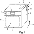
- FIG. 1 a schematic representation of a steamer 1 is shown.
- the steamer 1 has a housing 2 .
- a muffle 3 is arranged in the housing 2 . This delimits a cooking chamber 4 with its walls.
- the cooking chamber 4 is closed at the front by a door 5 of the steamer 1 . This is in 1 shown in closed condition.
- the steam cooking appliance 1 can also have an operating and/or display device 6 .
- the steam cooking appliance 1 can have a control unit 7 .
- the steamer 1 has a steam generating device or a steam generating system 8 . This is arranged in the housing 2 . It is arranged outside of the cooking space 4 . In particular, it can be arranged in an intermediate space between the housing 2 and the muffle 3 .
- the steam generation system 8 is arranged behind the muffle 3 in the depth direction (z-direction).
- the steamer 1 also has a separate tank 9 .
- the tank 9 is arranged in the housing 2 . It is arranged in a space between the housing 2 and the muffle 3 . Viewed in the height direction (y-direction) of the steam cooking appliance 1 , the tank 9 is arranged completely above a fluid line container 10 of the steam generation system 11 .
- This tank 9 is fluidly connected by lines to the liquid container 10 spaced therefrom.
- a fluid line is formed from the tank 9 to the liquid container 10 on the basis of gravity. This means that the liquid, in particular the water, flows from the tank 9 to the liquid container 10 purely on the basis of gravity.
- a pump is not provided in this regard.
- the steamer 1 has a pump 11 .
- the pump 11 is arranged in the housing 2 . In particular, it is arranged above the muffle 3 .
- the pump 11 is intended to convey liquid from the liquid container 10 to the tank 9 . In particular, the pump 11 is only intended and used to convey the liquid from the liquid container 10 to the tank 9 .
- FIG. 2 a partial detail of the steamer 1 is shown in an enlarged view.
- the housing 2 is not shown here.
- the interior of the housing 2 is therefore viewed.
- other device components are arranged above a muffle 3 (not shown).
- It can be a ventilation shaft 12, for example.
- a support plate 13 is provided for this purpose.
- the pump 11 can be arranged, in particular fastened, on this support plate 13 .
- the tank 9 can be arranged on this support plate 13 .
- the steam generation system 8 is shown.
- the liquid container 10 is shown here.
- an evaporator 14 of the vapor generation system 8 is shown.
- a vapor separator 15 of the vapor generation system 8 is shown in the exemplary embodiment.
- the tank 9 has an outer housing 16 .
- an inner housing 17 of the tank 9 is arranged therein.
- the liquid, in particular the water, is introduced directly into the inner housing 17 .
- the steamer 1 has a fluid line adapter 18 .
- the fluid line adapter 18 is coupled directly to the tank 9 .
- the steamer 1 has a coupling socket 19 . This is directly connected to the fluid line adapter 18 .
- the tank 9 is indirectly fluidly connected to the liquid container 10 via the fluid line adapter 18 .
- the coupling piece 19 is connected directly to an inlet 21 of the liquid container 10 by a line 20 .
- an outlet 22 of the liquid container 10 is connected to the pump 11 by a line 23 .
- the pump 11 is also connected in a fluid-conducting manner to the fluid line adapter 18 by a line 24 with an adapter inlet 25 .
- the tank 9 has a ventilation nozzle 26 . Air in the tank 9, in particular in the inner housing 17, can easily escape via this.
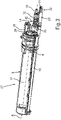
- FIG. 3 a perspective view of an arrangement 27 is shown.
- This has the tank 9 , the fluid line adapter 18 and the coupling piece 19 .
- the fluid line adapter 18 is directly coupled to the tank 9 with a push-pull system 28 .
- the outer housing 16 is connected directly to a support base 29 .
- the coupling socket 19 is arranged in a stationary manner on the carrier base 29 .
- the carrier base 29 is arranged directly on the device component, in particular the carrier plate 13 .
- a movable attachment can be provided for this purpose.
- the carrier base 29 can have a slot 31 on a base 30 .
- a fastening unit for example a screw, can be passed through this elongated hole 31 .
- a displacement movement of the carrier base 29 relative to the carrier plate 13 can be made possible through the elongated hole 31 .
- the carrier base 29 is connected to the outer housing 16 in a movement-coupled manner, a displacement movement of the outer housing 16 can also cause a corresponding displacement of the carrier base 29 .
- the push-pull system 28 can be positioned in particular at least the outer housing 16 of the tank 9 in at least two different positions along a longitudinal axis A.
- the longitudinal axis A is here both the longitudinal axis of the tank 9. It can be a longitudinal axis that runs parallel to a longitudinal axis of the fluid line adapter 18.
- this longitudinal axis A also runs parallel to a longitudinal axis B of the coupling piece 19.
- the tank 9, the fluid line adapter 18 and the coupling piece 9 are thus arranged in series along this longitudinal axis.
- an adapter outer housing 32 of the fluid line adapter 18 is arranged or mounted so that it can move relative to the outer housing 16 and the carrier base 29 between the tank 9 and the coupling socket 19 . Therefore, if the position of the tank 9, in particular the outer housing 16, is adjusted along the longitudinal axis A, this also leads in particular to a corresponding displacement of the carrier base 29 with the coupling piece 19 arranged stationary thereon.
- the coupling piece 19 is mounted in the adapter outer housing 32 so that it can move relatively .
- a relative movement is then also carried out in the outer adapter housing 32 . Because of these relative movement possibilities, a first fluid line path in the fluid line adapter 18 or a different second fluid line path in the fluid line adapter 18 is then automatically released or blocked.
- the longitudinal axis B of the fluid line adapter 18 is also shown. In the exemplary embodiment, this is also the longitudinal axis of the coupling socket 19.
- the adapter outer housing 32 is in 3 drawn in dashed lines and thus indicated transparently, so that the inner workings of the fluid line adapter 18 can be seen.
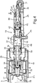
- FIG. 12 is a horizontal sectional view through the arrangement 27 according to FIG 3 shown in the area of the fluid line adapter 18 and the coupling piece 19 .
- the sectional plane is formed by the depth direction and the width direction (x-direction) of the steamer 1 .
- the tank 9 has a line socket 33 .
- the fluid line adapter 18 has an insertion socket 34 .
- this insertion socket 34 is arranged in a stationary manner in the outer adapter housing 32 . It is arranged at the end in such a way that it extends out of the adapter outer housing 32 .
- the insertion socket 34 is installed in a stationary manner in the adapter outer housing 32 .
- radial connecting elements 35 engage in a recess 36 in the jacket wall of the outer housing 32 .
- a seal 37 can be provided, with which the interface between the inside of the adapter outer housing 32 and the insertion socket 34 is sealed.
- the insertion socket 34 is coupled into the line socket 33 .
- a state is shown in which the tank 9, in particular the outer housing 16, is arranged in an end position.
- this is a first displacement position.
- a first fluid line path 40 of the fluid line adapter 18 is automatically released. This means that liquid can flow on this first, predefined fluid line path 40 into the coupling piece 19 and from there into the in 4 not shown line 20 can flow.
- the relevant principle of gravity enables this flow of the fluid.
- a specific relative position between the outer housing 16, the fluid line adapter 18 and the coupling piece 19 is set here in the direction of the longitudinal axes A and B.
- the coupling piece 19 protrudes into the adapter outer housing 32 and is movably mounted therein along the longitudinal axis B.
- a relative movement between the coupling piece 19 and the adapter outer housing 32 is thus made possible in this regard.
- the fluid then flows through the fluid line adapter 18 along the illustrated arrows P2 on this first fluid line path 40 .
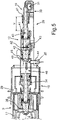
- the outer adapter housing 32 is more or less pushed into the outer housing 16 than in 4 .
- the coupling stub 19 protrudes in the position in figure 5 further out of an adapter outlet 41 of the fluid line adapter 18, in particular of the adapter outer housing 32, than in the state in 4 . This therefore means that with this linear displacement of the outer housing 16 relative to the fluid line adapter 18 there is also automatically a relative displacement of the coupling socket 19 relative to the fluid line adapter 18 .
- the first fluid line path 40 in the fluid line adapter 18 is automatically blocked.
- no fluid is conveyed from the liquid container 10 back to the tank 9.
- the line 22 is filled and in the filled state, when the outlet 22 is closed, no more water can flow through, the complete flow on the first fluid line path 40 is made possible. That this second fluid line path 44 then in accordance with this state 4 is also open up to the closed exit 22 is then irrelevant.
- the plunger 42 sits in this closed position with a seal 45 on a stop 46, which is formed inside the adapter outer housing 32, firmly.
- This partial path 46 is both a component of the first fluid line path 40 and, at the same time, a component of the second fluid line path 44.
- a bidirectional Conducting the fluid from the tank 9 and into the tank 9 allows.
- this also shows the corresponding positional difference between the outer housing 16 and the fluid line adapter 18 .
- the adapter inlet 26 is connected to the liquid container 10 via a second line path 49
- the adapter outlet 41 is connected to the liquid container 10 via a first line path 48 .
- the first conduction path 48 and the second conduction path 49 are in 2 symbolically marked.
- the fluid line adapter 18 forms a structural unit. This has the adapter outer housing 32 in which the fluid line paths 40 and 44 are formed.
- the first fluid line path 40 is part of a gravity fluid line path, which is formed in particular by the first line path 48 .
- the second fluid line path 44 is part of a pump fluid line path, which is formed in particular by the second line path 49 .
- the tank 9 can be completely removed from the housing 2 . In this regard, it can then be filled externally with water. This also improves the cleanability.
Landscapes
- Engineering & Computer Science (AREA)
- Chemical & Material Sciences (AREA)
- Combustion & Propulsion (AREA)
- Mechanical Engineering (AREA)
- General Engineering & Computer Science (AREA)
- Cookers (AREA)
Applications Claiming Priority (1)
| Application Number | Priority Date | Filing Date | Title |
|---|---|---|---|
| DE102021202846.2A DE102021202846A1 (de) | 2021-03-23 | 2021-03-23 | Dampfgargerät mit spezifischem Fluidleitungssystem, sowie Verfahren |
Publications (1)
| Publication Number | Publication Date |
|---|---|
| EP4063742A1 true EP4063742A1 (fr) | 2022-09-28 |
Family
ID=80628807
Family Applications (1)
| Application Number | Title | Priority Date | Filing Date |
|---|---|---|---|
| EP22160249.3A Withdrawn EP4063742A1 (fr) | 2021-03-23 | 2022-03-04 | Appareil à vapeur pourvu de système spécifique de conduite de fluide |
Country Status (2)
| Country | Link |
|---|---|
| EP (1) | EP4063742A1 (fr) |
| DE (1) | DE102021202846A1 (fr) |
Citations (7)
| Publication number | Priority date | Publication date | Assignee | Title |
|---|---|---|---|---|
| EP2083223A1 (fr) * | 2006-11-02 | 2009-07-29 | Sharp Kabushiki Kaisha | Dispositif pour diluer la vapeur déchargée et cuisinière en étant dotée |
| FR2958724A1 (fr) * | 2010-04-09 | 2011-10-14 | Fagorbrandt Sas | Four de cuisson comprenant au moins un dispositif de guidage d'une conduite de circulation d'eau entre un tiroir de remplissage d'eau et un reservoir d'eau. |
| EP2518413A2 (fr) * | 2011-04-28 | 2012-10-31 | Samsung Electronics Co., Ltd. | Appareil de cuisson à la vapeur |
| DE102012200289A1 (de) * | 2012-01-11 | 2013-07-11 | BSH Bosch und Siemens Hausgeräte GmbH | Haushalts-Dampfgargerät mit außerhalb des Behandlungsraums angeordnetem Dampferzeuger |
| EP3180984A1 (fr) | 2015-12-18 | 2017-06-21 | BSH Hausgeräte GmbH | Appareil de cuisson |
| EP3553393A1 (fr) * | 2018-04-12 | 2019-10-16 | LG Electronics Inc. | Appareil de cuisson |
| DE102019201462A1 (de) * | 2019-02-05 | 2020-08-06 | BSH Hausgeräte GmbH | Gargerät mit einer Dampferzeugungsvorrichtung, die eine Regulierungseinrichtung mit zumindest einem Schwimmerventil aufweist, sowie Verfahren zum Betreiben einer Dampferzeugungsvorrichtung |
Family Cites Families (3)
| Publication number | Priority date | Publication date | Assignee | Title |
|---|---|---|---|---|
| US7537004B2 (en) | 2005-05-03 | 2009-05-26 | Whirlpool Corporation | Steam oven with fluid supply and drain vessel |
| DE102017214932A1 (de) | 2017-08-25 | 2019-02-28 | BSH Hausgeräte GmbH | Dampfgargerät |
| DE102017214928A1 (de) | 2017-08-25 | 2019-02-28 | BSH Hausgeräte GmbH | Dampfgargerät |
-
2021
- 2021-03-23 DE DE102021202846.2A patent/DE102021202846A1/de active Pending
-
2022
- 2022-03-04 EP EP22160249.3A patent/EP4063742A1/fr not_active Withdrawn
Patent Citations (8)
| Publication number | Priority date | Publication date | Assignee | Title |
|---|---|---|---|---|
| EP2083223A1 (fr) * | 2006-11-02 | 2009-07-29 | Sharp Kabushiki Kaisha | Dispositif pour diluer la vapeur déchargée et cuisinière en étant dotée |
| FR2958724A1 (fr) * | 2010-04-09 | 2011-10-14 | Fagorbrandt Sas | Four de cuisson comprenant au moins un dispositif de guidage d'une conduite de circulation d'eau entre un tiroir de remplissage d'eau et un reservoir d'eau. |
| EP2375169B1 (fr) | 2010-04-09 | 2013-06-26 | FagorBrandt SAS | Four de cuisson comprenant un dispositif de guidage d'une conduite de circulation d'eau entre un tiroir de remplissage d'eau et un réservoir d'eau. |
| EP2518413A2 (fr) * | 2011-04-28 | 2012-10-31 | Samsung Electronics Co., Ltd. | Appareil de cuisson à la vapeur |
| DE102012200289A1 (de) * | 2012-01-11 | 2013-07-11 | BSH Bosch und Siemens Hausgeräte GmbH | Haushalts-Dampfgargerät mit außerhalb des Behandlungsraums angeordnetem Dampferzeuger |
| EP3180984A1 (fr) | 2015-12-18 | 2017-06-21 | BSH Hausgeräte GmbH | Appareil de cuisson |
| EP3553393A1 (fr) * | 2018-04-12 | 2019-10-16 | LG Electronics Inc. | Appareil de cuisson |
| DE102019201462A1 (de) * | 2019-02-05 | 2020-08-06 | BSH Hausgeräte GmbH | Gargerät mit einer Dampferzeugungsvorrichtung, die eine Regulierungseinrichtung mit zumindest einem Schwimmerventil aufweist, sowie Verfahren zum Betreiben einer Dampferzeugungsvorrichtung |
Also Published As
| Publication number | Publication date |
|---|---|
| DE102021202846A1 (de) | 2022-09-29 |
Similar Documents
| Publication | Publication Date | Title |
|---|---|---|
| DE102007036844B4 (de) | Verfahren zum Betrieb einer hydropneumatischen Vorrichtung zur Druckübersetzung | |
| DE102011050037B3 (de) | Steckereinheit und Verbindungssystem zum Verbinden von Kapillaren, insbesondere für die Hochleistungsflüssigkeitschromatographie | |
| EP1423614B1 (fr) | Transmetteur de pression | |
| DE202017003295U1 (de) | Arbeitsmaschinen-Einspannvorrichtung mit Bilderfassungsfunktion | |
| EP4063742A1 (fr) | Appareil à vapeur pourvu de système spécifique de conduite de fluide | |
| DE102005051598B4 (de) | Betriebsfluid-Zuführvorrichtung | |
| EP3253351A1 (fr) | Table d'opération | |
| DE102020210289B3 (de) | Fluidbetätigter Linearantrieb | |
| EP2735321B1 (fr) | Support de cartouches pour une machine de dialyse | |
| DE102019213522A1 (de) | Getriebeölmodul für eine Getriebeeinrichtung | |
| EP2705268B1 (fr) | Parcours hydraulique doté d'un dispositif d'évacuation de l'air | |
| EP1605109A1 (fr) | Cuvette de WC | |
| EP2952810A1 (fr) | Armature destinee a filtrer des milieux liquides | |
| DE202007003861U1 (de) | Hubdüse, insbesondere in einer Scheinwerferreinigungsanlage | |
| DE102017202083A1 (de) | Schmiermittelreservoirsystem | |
| DE20300666U1 (de) | Anschlussvorrichtung für Fluidleitungen | |
| DD298167A5 (de) | Vorrichtung zur ueberwachung des durchflusses eines fliessfaehigen mediums durch einen stroemungsraum | |
| DE20303877U1 (de) | Handgeführtes Preßgerät | |
| DE102005031221A1 (de) | Siebvorrichtung | |
| WO2022130166A1 (fr) | Dispositif d'installation pour l'installation d'un dispositif de séparation d'échantillon | |
| EP3366851B1 (fr) | Ensemble soupape de remplissage universel | |
| DE202015105045U1 (de) | Kreuzgelenkrohrverbindung | |
| EP0004858A2 (fr) | Appareil pour cintrer des tubes | |
| DE102006024095A1 (de) | Druckanschlussvorrichtung für eine Führungsdrahteinheit | |
| DE102006017077B4 (de) | Vorrichtung zum Aufbringen eines Befettungsmittels auf eine Werkstückoberfläche |
Legal Events
| Date | Code | Title | Description |
|---|---|---|---|
| PUAI | Public reference made under article 153(3) epc to a published international application that has entered the european phase |
Free format text: ORIGINAL CODE: 0009012 |
|
| STAA | Information on the status of an ep patent application or granted ep patent |
Free format text: STATUS: THE APPLICATION HAS BEEN PUBLISHED |
|
| AK | Designated contracting states |
Kind code of ref document: A1 Designated state(s): AL AT BE BG CH CY CZ DE DK EE ES FI FR GB GR HR HU IE IS IT LI LT LU LV MC MK MT NL NO PL PT RO RS SE SI SK SM TR |
|
| STAA | Information on the status of an ep patent application or granted ep patent |
Free format text: STATUS: REQUEST FOR EXAMINATION WAS MADE |
|
| 17P | Request for examination filed |
Effective date: 20230328 |
|
| RBV | Designated contracting states (corrected) |
Designated state(s): AL AT BE BG CH CY CZ DE DK EE ES FI FR GB GR HR HU IE IS IT LI LT LU LV MC MK MT NL NO PL PT RO RS SE SI SK SM TR |
|
| GRAP | Despatch of communication of intention to grant a patent |
Free format text: ORIGINAL CODE: EPIDOSNIGR1 |
|
| STAA | Information on the status of an ep patent application or granted ep patent |
Free format text: STATUS: GRANT OF PATENT IS INTENDED |
|
| INTG | Intention to grant announced |
Effective date: 20231110 |
|
| STAA | Information on the status of an ep patent application or granted ep patent |
Free format text: STATUS: THE APPLICATION IS DEEMED TO BE WITHDRAWN |
|
| 18D | Application deemed to be withdrawn |
Effective date: 20240312 |