EP4063780A1 - Appareil pour le stockage et la récupération de chaleur résiduelle dans une couche naturelle d'eau - Google Patents
Appareil pour le stockage et la récupération de chaleur résiduelle dans une couche naturelle d'eau Download PDFInfo
- Publication number
- EP4063780A1 EP4063780A1 EP21210998.7A EP21210998A EP4063780A1 EP 4063780 A1 EP4063780 A1 EP 4063780A1 EP 21210998 A EP21210998 A EP 21210998A EP 4063780 A1 EP4063780 A1 EP 4063780A1
- Authority
- EP
- European Patent Office
- Prior art keywords
- extraction
- discharge
- water
- well
- heat storage
- Prior art date
- Legal status (The legal status is an assumption and is not a legal conclusion. Google has not performed a legal analysis and makes no representation as to the accuracy of the status listed.)
- Granted
Links
Images
Classifications
-
- F—MECHANICAL ENGINEERING; LIGHTING; HEATING; WEAPONS; BLASTING
- F28—HEAT EXCHANGE IN GENERAL
- F28D—HEAT-EXCHANGE APPARATUS, NOT PROVIDED FOR IN ANOTHER SUBCLASS, IN WHICH THE HEAT-EXCHANGE MEDIA DO NOT COME INTO DIRECT CONTACT
- F28D20/00—Heat storage plants or apparatus in general; Regenerative heat-exchange apparatus not covered by groups F28D17/00 or F28D19/00
- F28D20/0034—Heat storage plants or apparatus in general; Regenerative heat-exchange apparatus not covered by groups F28D17/00 or F28D19/00 using liquid heat storage material
- F28D20/0043—Heat storage plants or apparatus in general; Regenerative heat-exchange apparatus not covered by groups F28D17/00 or F28D19/00 using liquid heat storage material specially adapted for long-term heat storage; Underground tanks; Floating reservoirs; Pools; Ponds
-
- F—MECHANICAL ENGINEERING; LIGHTING; HEATING; WEAPONS; BLASTING
- F28—HEAT EXCHANGE IN GENERAL
- F28F—DETAILS OF HEAT-EXCHANGE AND HEAT-TRANSFER APPARATUS, OF GENERAL APPLICATION
- F28F27/00—Control arrangements or safety devices specially adapted for heat-exchange or heat-transfer apparatus
- F28F27/02—Control arrangements or safety devices specially adapted for heat-exchange or heat-transfer apparatus for controlling the distribution of heat-exchange media between different channels
-
- Y—GENERAL TAGGING OF NEW TECHNOLOGICAL DEVELOPMENTS; GENERAL TAGGING OF CROSS-SECTIONAL TECHNOLOGIES SPANNING OVER SEVERAL SECTIONS OF THE IPC; TECHNICAL SUBJECTS COVERED BY FORMER USPC CROSS-REFERENCE ART COLLECTIONS [XRACs] AND DIGESTS
- Y02—TECHNOLOGIES OR APPLICATIONS FOR MITIGATION OR ADAPTATION AGAINST CLIMATE CHANGE
- Y02E—REDUCTION OF GREENHOUSE GAS [GHG] EMISSIONS, RELATED TO ENERGY GENERATION, TRANSMISSION OR DISTRIBUTION
- Y02E60/00—Enabling technologies; Technologies with a potential or indirect contribution to GHG emissions mitigation
- Y02E60/14—Thermal energy storage
Definitions
- the subject of the invention is a device arrangement for accumulating excess heat in a natural water-permeable layer and for its recovery, applicable in the underground storage of excess heat, especially in its efficient use.
- a mixture of water and gravel is used as a storage medium, located in a hole dug in the ground and thermally insulated from the surrounding ground and from the atmosphere by means of a plastic film. Hot water is drawn directly from the reservoir or through a coil arranged in the reservoir.
- controllable valves are built into surface sections of the pipeline, to which drain pipelines are connected and introduced to both wells.
- the solution ensures easy and quick change of the well function from extraction to absorbent one and vice versa, through appropriate setting the controllable valves.
- the heat pump is used for air conditioning and cooling, and the recuperative heat from the heat pump is discharged with the water into the aquifer, where it is collected for use during the winter period.
- the wells perform alternately the functions of extraction or discharge wells.
- Japanese patent specification JP6325835B2 discloses a method of storing heat in a labyrinthine tank formed in the area of a water-permeable layer situated between impermeable layers.
- the tank is separated by contouring parts of the water-permeable layer with impermeable, vertical walls from the surface to a depth below the ceiling of the underlying impermeable layer and by providing a closed area inside the vertical, impermeable partitions forming a labyrinth-shaped channel, maximizing the length of a flow path between holes drilled from the surface: a discharge hole and an extraction hole, connected, by means of pumps, to a heat exchanger, to which air conditioning can be further connected.
- Water stored in a water-permeable layer also insulated from the surface can be used to heat rooms, and to cool them in summer.
- the invention solves the technical problem of a method of storing heat in natural water-permeable layers - ATES (Aquifer Thermal Energy Storage), consisting in the inability to use it in water-permeable layers with low water accumulation or with significant water outflow from the area designated for the storage, while ensuring high efficiency and low thermal inertia.
- ATES Anafer Thermal Energy Storage
- the essence of the device arrangement for accumulating excess heat in a natural water-permeable layer and for its recovery comprising a heat storage filled with water, which constitutes a closed area, separated from the water-permeable layer by means of anti-filtration walls, being vertical or having slope close to vertical, made of the ground surface to a depth below the floor of the water-permeable layer, and comprising at least one extraction well situated in this area and a heat exchanger, at least one discharge well and at least one pump, consists in that the anti-filtration walls are diaphragm walls that constitute a thermally insulating partition, wherein the extraction well and the discharge well are constitued by one dual-function extraction-discharge well equipped with a discharge pipeline and an extraction pipeline hydraulically connected to the pump directly or indirectly, wherein the pump is connected by means of an electric power cable to a frequency converter which has a signal connection to a checking, measuring and control equipment, which furthermore has a signal connection to multilevel temperature and water level measuring probes located in the extraction-discharge well and
- the checking, measuring and control equipment has a signal connection to controllable valves situated on hydraulic lines that connect an extraction collector to an extraction pipeline, and to controllable valves situated on hydraulic lines that connect a discharge collector to a discharge pipeline.
- the extraction and discharge collectors are led to the heat exchanger, and the heat storage is covered on top with a horizontal partition that constitutes an anti-filtration cover and thermal insulation.
- the heat storage is additionally covered with a layer of soil lying on the horizontal partition, which allows to ensure the biological function on the surface, above the heat storage. It is preferable that between the established water level in the heat storage and the horizontal partition, there is a waterless space filled with soil air, that constitutes an additional thermal insulation.
- the pump is a pump or a pump set installed on a surface between the extraction collector and the heat exchanger.
- the pump is a submersible pump, installed in place of a suction stainer, on the extraction pipeline.
- the walls of the heat storage form a ring shape when they are projected on a horizontal plane.
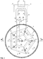
- the arrangment comprises dual-function extraction-discharge wells arranged such that one well is situated in the middle of the heat storage, and the others are arranged evenly at a constant distance from the center, wherein in directions representing the bisector of an angle defined by the two adjacent extraction-discharge wells and the central extraction-discharge well, the control and measurement holes are located.
- Fig. 1 shows schematically a top view of an underground excess heat storage along with an installation diagram on the surface
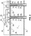
- Fig. 2 shows schematically a vertical cross-section through the center of the underground excess heat storage separated in a natural water-permeable layer, along with an installation on the surface.
- a device arrangement for accumulating excess heat in a natural water-permeable layer and for its recovery comprises an underground heat storage 1 made in a natural part of a water-permeable layer 2, covered with a horizontal partition 3 that constitutes a thermal and filtration insulation and a layer of soil 4 lying thereon.
- the natural water-permeable layer 2 is limited by a vertical anti-filtration wall 5 constituting a thermal and filtration insulation, forming a ring-shaped closed area having an inner radius of 52 m.
- the vertical wall 5 is recessed over a distance of 1 m into a natural impermeable layer 6, lying under the natural water-permeable layer 2.
- a water table level 24 in the heat storage 1 is above the natural underground water level 7 in the natural water-permeable layer 2.
- each dual-function extraction-discharge well 8 there is a vertical extraction pipeline 10, ended at the lower part with a suction stainer 11 with a check valve, submerged below the dynamic level of the water table 24 existing in that well, and the upper end of the extraction pipeline 10 is connected to an extraction collector 12 through a controllable valve 21. Furthermore, in each dual-function extraction-discharge well 8 there is a vertical discharge pipeline 13, the lower end of which is situated at the lower part of the underground heat storage 1, and the upper end is connected to a discharge collector 14 through a controllable valve 22.
- the extraction collector 12 and the discharge collector 14, made in the technology of pre-insulated pipes and located below the ground surface, are led to the heat exchanger 15, to which a heat supply installation 16 and a heat collection installation 17 are also connected.
- each dual-function extraction-discharge well 8 in each control and measurement hole 9 and in the heat exchanger 15 there are multilevel temperature and water level measuring probes 18 connected by means of a signal wire 26 to a checking, measuring and control equipment 19, which in turn is connected, by means of the signal wire 26, to the frequency converter 23 and to the controllable valves 21 and 22.
- a waterless space 25 filled with soil air, that constitutes an additional thermal insulation.
- a method of its operation can be presented.
- the multilevel measuring probes 18 transmitting readings to the checking, measuring and control equipment 19, the vertical temperature field distribution and the water table level 24 in the underground excess heat storage 1 as well as the temperature field distribution in the heat exchanger 15 are controlled.
- the water table level 24 in the heat storage 1 needs to be raised, it is supplemented with a set of pumps (not shown in the drawing) from the area of the natural water-permeable layer 2 or from another water source.
- the extraction, discharge function or temporary exclusion of individual wells 8 is determined in each case on the basis of measurement data obtained from all the multilevel measuring probes 18.
- a dedicated software of the checking, measuring and control equipment 19 individually determines the operating mode of each well 8 in real time, depending on the temperature field distribution in the space of the heat storage 1. Circulating water flow rate in the vertical extraction pipeline 10, the extraction collector 12, the discharge pipeline 13, and the discharge collector 14 depends on the operation of the pump set 20, in which the rotational speed control is applied by means of the frequency converter 23, controlled by the checking, measuring and control equipment 19.
- the checking, measuring and control equipment 19 turns the pump set 20 on and off depending on the pressure in the cummulative discharge collector 14 and on the temperature value measured by the multilevelymi measuring probes 18, and also individually controls the controllable valves 21 and 22 that regulate hot water extraction in order to transfer heat through the heat exchanger 15 to the accumulated heat collection installation 17 or its discharge to the heat storage 1, after it has been collected in the heat exchanger 15 from the excess heat supply installation 16.
- the signal transmission between the measuring probes 18, the checking, measuring and control equipment 19, the pump set 20 and the frequency converter 23, as well as the controllable valves 21 regulating water extraction and the controllable valves 22 regulating water discharge is performed wirelessly, by means of radio waves.
- the pumps 20 are submersible pumps, installed in each dual-function extraction-discharge well 8 in place of the suction stainer 11.
- the pumps 20 are elecrically powered and their operation is individually regulated by the checking, measuring and control equipment 19 using the frequency converter 23.
Landscapes
- Engineering & Computer Science (AREA)
- Physics & Mathematics (AREA)
- Thermal Sciences (AREA)
- Mechanical Engineering (AREA)
- General Engineering & Computer Science (AREA)
- Sewage (AREA)
- Heat-Exchange Devices With Radiators And Conduit Assemblies (AREA)
- Investigation Of Foundation Soil And Reinforcement Of Foundation Soil By Compacting Or Drainage (AREA)
- Other Air-Conditioning Systems (AREA)
Applications Claiming Priority (1)
| Application Number | Priority Date | Filing Date | Title |
|---|---|---|---|
| PL437388A PL248700B1 (pl) | 2021-03-24 | 2021-03-24 | Układ urządzeń do akumulacji ciepła nadmiarowego w naturalnej warstwie wodoprzepuszczalnej oraz do jego odzysku |
Publications (3)
| Publication Number | Publication Date |
|---|---|
| EP4063780A1 true EP4063780A1 (fr) | 2022-09-28 |
| EP4063780B1 EP4063780B1 (fr) | 2023-11-08 |
| EP4063780C0 EP4063780C0 (fr) | 2023-11-08 |
Family
ID=80784800
Family Applications (1)
| Application Number | Title | Priority Date | Filing Date |
|---|---|---|---|
| EP21210998.7A Active EP4063780B1 (fr) | 2021-03-24 | 2021-11-29 | Appareil pour le stockage et la récupération de chaleur résiduelle dans une couche naturelle d'eau |
Country Status (2)
| Country | Link |
|---|---|
| EP (1) | EP4063780B1 (fr) |
| PL (1) | PL248700B1 (fr) |
Cited By (2)
| Publication number | Priority date | Publication date | Assignee | Title |
|---|---|---|---|---|
| CN117051941A (zh) * | 2023-08-30 | 2023-11-14 | 苏州上扬环境技术有限公司 | 一种不断水施工修复检查井的方法 |
| CN119801630A (zh) * | 2025-01-08 | 2025-04-11 | 西安科技大学 | 一种矿山地下空间响应式增强型储热充填系统及储能方法 |
Citations (8)
| Publication number | Priority date | Publication date | Assignee | Title |
|---|---|---|---|---|
| DE2657244A1 (de) * | 1975-12-23 | 1977-07-07 | Atomenergi Ab | Warmwasserreservoir |
| CH594795A5 (en) * | 1976-08-05 | 1978-01-31 | Pierino Tosi | Thermic energy storage with water as medium |
| FR2504099A2 (fr) * | 1979-08-08 | 1982-10-22 | Coste Jean | Procede de stockage calorifuge de grandes quantites d'eau chaude, et moyens pour sa mise en oeuvre |
| US4399656A (en) * | 1974-09-30 | 1983-08-23 | Nikolaus Laing | Long-period thermal storage accumulators |
| DE3232268A1 (de) * | 1982-04-03 | 1983-10-06 | Erdmann Horst | Langzeit-energiespeicher fuer heizzwecke |
| JPS6325835B2 (fr) | 1979-08-30 | 1988-05-26 | Shin Meiwa Ind Co Ltd | |
| PL217289B1 (pl) | 2010-10-04 | 2014-07-31 | Akademia Górniczo Hutnicza Im Stanisława Staszica W Krakowie | Układ instalacji geotermii płytkiej |
| KR101670007B1 (ko) | 2016-06-15 | 2016-10-27 | 한국지역난방기술 (주) | 열원의 공급온도에 따라 축열 공간의 선택이 가능한 보어홀 방식의 계간 축열 시스템 |
-
2021
- 2021-03-24 PL PL437388A patent/PL248700B1/pl unknown
- 2021-11-29 EP EP21210998.7A patent/EP4063780B1/fr active Active
Patent Citations (8)
| Publication number | Priority date | Publication date | Assignee | Title |
|---|---|---|---|---|
| US4399656A (en) * | 1974-09-30 | 1983-08-23 | Nikolaus Laing | Long-period thermal storage accumulators |
| DE2657244A1 (de) * | 1975-12-23 | 1977-07-07 | Atomenergi Ab | Warmwasserreservoir |
| CH594795A5 (en) * | 1976-08-05 | 1978-01-31 | Pierino Tosi | Thermic energy storage with water as medium |
| FR2504099A2 (fr) * | 1979-08-08 | 1982-10-22 | Coste Jean | Procede de stockage calorifuge de grandes quantites d'eau chaude, et moyens pour sa mise en oeuvre |
| JPS6325835B2 (fr) | 1979-08-30 | 1988-05-26 | Shin Meiwa Ind Co Ltd | |
| DE3232268A1 (de) * | 1982-04-03 | 1983-10-06 | Erdmann Horst | Langzeit-energiespeicher fuer heizzwecke |
| PL217289B1 (pl) | 2010-10-04 | 2014-07-31 | Akademia Górniczo Hutnicza Im Stanisława Staszica W Krakowie | Układ instalacji geotermii płytkiej |
| KR101670007B1 (ko) | 2016-06-15 | 2016-10-27 | 한국지역난방기술 (주) | 열원의 공급온도에 따라 축열 공간의 선택이 가능한 보어홀 방식의 계간 축열 시스템 |
Non-Patent Citations (1)
| Title |
|---|
| J. CHODURY: "Instalacje sloneczne. Dobor, montaz i nowe konstrukcje kolektorow", RYNEK INSTALACYJNY, WYD.: DOM WYDAWNICZY MEDIUM, WARSZAWA, 2011 |
Cited By (2)
| Publication number | Priority date | Publication date | Assignee | Title |
|---|---|---|---|---|
| CN117051941A (zh) * | 2023-08-30 | 2023-11-14 | 苏州上扬环境技术有限公司 | 一种不断水施工修复检查井的方法 |
| CN119801630A (zh) * | 2025-01-08 | 2025-04-11 | 西安科技大学 | 一种矿山地下空间响应式增强型储热充填系统及储能方法 |
Also Published As
| Publication number | Publication date |
|---|---|
| EP4063780B1 (fr) | 2023-11-08 |
| PL248700B1 (pl) | 2026-01-19 |
| EP4063780C0 (fr) | 2023-11-08 |
| PL437388A1 (pl) | 2022-09-26 |
Similar Documents
| Publication | Publication Date | Title |
|---|---|---|
| US3965972A (en) | Heating and cooling system | |
| KR101524820B1 (ko) | 지열 에너지 시스템 및 작동 방법 | |
| EP2176548B1 (fr) | Système d'énergie géothermique et procédé de fonctionnement | |
| JP5963790B2 (ja) | 地下水循環型地中熱採熱システム及び地中熱利用冷暖房又は給湯システム | |
| CN109340864A (zh) | 一种中深层与浅层地热能联合供热及浅层地热能补热系统 | |
| RU2429428C2 (ru) | Система и распределительная цистерна для сети низкотемпературной энергии | |
| EP4063780B1 (fr) | Appareil pour le stockage et la récupération de chaleur résiduelle dans une couche naturelle d'eau | |
| CN202547190U (zh) | 地源热泵的地埋管系统 | |
| EP2619509B1 (fr) | Système pour stocker de l'énergie thermique, ensemble de chauffage comprenant ledit système et procédé de fabrication dudit système | |
| JPH08184063A (ja) | 地中蓄熱装置 | |
| CN209084867U (zh) | 一种中深层与浅层地热能联合供热及浅层地热能补热系统 | |
| WO2022260584A1 (fr) | Stockage d'énergie thermique et procédé de régulation d'un stockage d'énergie thermique | |
| CN113668644A (zh) | 一种单井双管式含水层储能系统 | |
| GB2482435A (en) | Geothermal energy system and method of operation | |
| GB2482437A (en) | Geothermal energy system and method of operation | |
| GB2482436A (en) | Geothermal energy system and method of operation | |
| CN116839959A (zh) | 一种双u型地埋管地源热泵的测试方法 | |
| CN203068876U (zh) | 高效扰动式地源热泵换热器 | |
| RU2717890C1 (ru) | Способ подземного аккумулирования тепла или холода | |
| CN201962730U (zh) | 高原永久冻土地带给水管路热媒伴管保温装置 | |
| RU2064141C1 (ru) | Геотермальная энергетическая установка | |
| CN208748857U (zh) | 地埋重力热管间接加热外墙保温系统 | |
| CN102853471B (zh) | 夏季蓄热式太阳能供暖洗浴系统 | |
| KR20160140309A (ko) | 단일 관정 지중 열교환기의 취수 및 환수 분리 시스템 | |
| RU2683059C1 (ru) | Способ извлечения и использования геотермального тепла для охлаждения грунтов вокруг тоннелей метрополитена |
Legal Events
| Date | Code | Title | Description |
|---|---|---|---|
| PUAI | Public reference made under article 153(3) epc to a published international application that has entered the european phase |
Free format text: ORIGINAL CODE: 0009012 |
|
| STAA | Information on the status of an ep patent application or granted ep patent |
Free format text: STATUS: THE APPLICATION HAS BEEN PUBLISHED |
|
| AK | Designated contracting states |
Kind code of ref document: A1 Designated state(s): AL AT BE BG CH CY CZ DE DK EE ES FI FR GB GR HR HU IE IS IT LI LT LU LV MC MK MT NL NO PL PT RO RS SE SI SK SM TR |
|
| STAA | Information on the status of an ep patent application or granted ep patent |
Free format text: STATUS: REQUEST FOR EXAMINATION WAS MADE |
|
| 17P | Request for examination filed |
Effective date: 20230310 |
|
| RBV | Designated contracting states (corrected) |
Designated state(s): AL AT BE BG CH CY CZ DE DK EE ES FI FR GB GR HR HU IE IS IT LI LT LU LV MC MK MT NL NO PL PT RO RS SE SI SK SM TR |
|
| GRAP | Despatch of communication of intention to grant a patent |
Free format text: ORIGINAL CODE: EPIDOSNIGR1 |
|
| STAA | Information on the status of an ep patent application or granted ep patent |
Free format text: STATUS: GRANT OF PATENT IS INTENDED |
|
| RIC1 | Information provided on ipc code assigned before grant |
Ipc: F28F 27/02 20060101AFI20230329BHEP |
|
| INTG | Intention to grant announced |
Effective date: 20230425 |
|
| RAP3 | Party data changed (applicant data changed or rights of an application transferred) |
Owner name: AKADEMIA GORNICZO-HUTNICZA IM. STANISLAWA STASZICA W KRAKOWIE |
|
| GRAS | Grant fee paid |
Free format text: ORIGINAL CODE: EPIDOSNIGR3 |
|
| GRAJ | Information related to disapproval of communication of intention to grant by the applicant or resumption of examination proceedings by the epo deleted |
Free format text: ORIGINAL CODE: EPIDOSDIGR1 |
|
| GRAL | Information related to payment of fee for publishing/printing deleted |
Free format text: ORIGINAL CODE: EPIDOSDIGR3 |
|
| STAA | Information on the status of an ep patent application or granted ep patent |
Free format text: STATUS: REQUEST FOR EXAMINATION WAS MADE |
|
| INTC | Intention to grant announced (deleted) | ||
| GRAP | Despatch of communication of intention to grant a patent |
Free format text: ORIGINAL CODE: EPIDOSNIGR1 |
|
| STAA | Information on the status of an ep patent application or granted ep patent |
Free format text: STATUS: GRANT OF PATENT IS INTENDED |
|
| GRAA | (expected) grant |
Free format text: ORIGINAL CODE: 0009210 |
|
| STAA | Information on the status of an ep patent application or granted ep patent |
Free format text: STATUS: THE PATENT HAS BEEN GRANTED |
|
| INTG | Intention to grant announced |
Effective date: 20230918 |
|
| AK | Designated contracting states |
Kind code of ref document: B1 Designated state(s): AL AT BE BG CH CY CZ DE DK EE ES FI FR GB GR HR HU IE IS IT LI LT LU LV MC MK MT NL NO PL PT RO RS SE SI SK SM TR |
|
| REG | Reference to a national code |
Ref country code: GB Ref legal event code: FG4D |
|
| REG | Reference to a national code |
Ref country code: CH Ref legal event code: EP |
|
| REG | Reference to a national code |
Ref country code: DE Ref legal event code: R096 Ref document number: 602021006627 Country of ref document: DE |
|
| REG | Reference to a national code |
Ref country code: IE Ref legal event code: FG4D |
|
| U01 | Request for unitary effect filed |
Effective date: 20231110 |
|
| U07 | Unitary effect registered |
Designated state(s): AT BE BG DE DK EE FI FR IT LT LU LV MT NL PT SE SI Effective date: 20231121 |
|
| U20 | Renewal fee for the european patent with unitary effect paid |
Year of fee payment: 3 Effective date: 20231116 |
|
| PG25 | Lapsed in a contracting state [announced via postgrant information from national office to epo] |
Ref country code: GR Free format text: LAPSE BECAUSE OF FAILURE TO SUBMIT A TRANSLATION OF THE DESCRIPTION OR TO PAY THE FEE WITHIN THE PRESCRIBED TIME-LIMIT Effective date: 20240209 |
|
| PG25 | Lapsed in a contracting state [announced via postgrant information from national office to epo] |
Ref country code: IS Free format text: LAPSE BECAUSE OF FAILURE TO SUBMIT A TRANSLATION OF THE DESCRIPTION OR TO PAY THE FEE WITHIN THE PRESCRIBED TIME-LIMIT Effective date: 20240308 |
|
| PG25 | Lapsed in a contracting state [announced via postgrant information from national office to epo] |
Ref country code: ES Free format text: LAPSE BECAUSE OF FAILURE TO SUBMIT A TRANSLATION OF THE DESCRIPTION OR TO PAY THE FEE WITHIN THE PRESCRIBED TIME-LIMIT Effective date: 20231108 |
|
| PG25 | Lapsed in a contracting state [announced via postgrant information from national office to epo] |
Ref country code: IS Free format text: LAPSE BECAUSE OF FAILURE TO SUBMIT A TRANSLATION OF THE DESCRIPTION OR TO PAY THE FEE WITHIN THE PRESCRIBED TIME-LIMIT Effective date: 20240308 Ref country code: GR Free format text: LAPSE BECAUSE OF FAILURE TO SUBMIT A TRANSLATION OF THE DESCRIPTION OR TO PAY THE FEE WITHIN THE PRESCRIBED TIME-LIMIT Effective date: 20240209 Ref country code: ES Free format text: LAPSE BECAUSE OF FAILURE TO SUBMIT A TRANSLATION OF THE DESCRIPTION OR TO PAY THE FEE WITHIN THE PRESCRIBED TIME-LIMIT Effective date: 20231108 |
|
| PG25 | Lapsed in a contracting state [announced via postgrant information from national office to epo] |
Ref country code: RS Free format text: LAPSE BECAUSE OF FAILURE TO SUBMIT A TRANSLATION OF THE DESCRIPTION OR TO PAY THE FEE WITHIN THE PRESCRIBED TIME-LIMIT Effective date: 20231108 Ref country code: PL Free format text: LAPSE BECAUSE OF FAILURE TO SUBMIT A TRANSLATION OF THE DESCRIPTION OR TO PAY THE FEE WITHIN THE PRESCRIBED TIME-LIMIT Effective date: 20231108 Ref country code: NO Free format text: LAPSE BECAUSE OF FAILURE TO SUBMIT A TRANSLATION OF THE DESCRIPTION OR TO PAY THE FEE WITHIN THE PRESCRIBED TIME-LIMIT Effective date: 20240208 Ref country code: HR Free format text: LAPSE BECAUSE OF FAILURE TO SUBMIT A TRANSLATION OF THE DESCRIPTION OR TO PAY THE FEE WITHIN THE PRESCRIBED TIME-LIMIT Effective date: 20231108 |
|
| PG25 | Lapsed in a contracting state [announced via postgrant information from national office to epo] |
Ref country code: CZ Free format text: LAPSE BECAUSE OF FAILURE TO SUBMIT A TRANSLATION OF THE DESCRIPTION OR TO PAY THE FEE WITHIN THE PRESCRIBED TIME-LIMIT Effective date: 20231108 |
|
| PG25 | Lapsed in a contracting state [announced via postgrant information from national office to epo] |
Ref country code: SK Free format text: LAPSE BECAUSE OF FAILURE TO SUBMIT A TRANSLATION OF THE DESCRIPTION OR TO PAY THE FEE WITHIN THE PRESCRIBED TIME-LIMIT Effective date: 20231108 |
|
| PG25 | Lapsed in a contracting state [announced via postgrant information from national office to epo] |
Ref country code: SM Free format text: LAPSE BECAUSE OF FAILURE TO SUBMIT A TRANSLATION OF THE DESCRIPTION OR TO PAY THE FEE WITHIN THE PRESCRIBED TIME-LIMIT Effective date: 20231108 Ref country code: SK Free format text: LAPSE BECAUSE OF FAILURE TO SUBMIT A TRANSLATION OF THE DESCRIPTION OR TO PAY THE FEE WITHIN THE PRESCRIBED TIME-LIMIT Effective date: 20231108 Ref country code: RO Free format text: LAPSE BECAUSE OF FAILURE TO SUBMIT A TRANSLATION OF THE DESCRIPTION OR TO PAY THE FEE WITHIN THE PRESCRIBED TIME-LIMIT Effective date: 20231108 Ref country code: CZ Free format text: LAPSE BECAUSE OF FAILURE TO SUBMIT A TRANSLATION OF THE DESCRIPTION OR TO PAY THE FEE WITHIN THE PRESCRIBED TIME-LIMIT Effective date: 20231108 |
|
| REG | Reference to a national code |
Ref country code: DE Ref legal event code: R097 Ref document number: 602021006627 Country of ref document: DE |
|
| PG25 | Lapsed in a contracting state [announced via postgrant information from national office to epo] |
Ref country code: MC Free format text: LAPSE BECAUSE OF FAILURE TO SUBMIT A TRANSLATION OF THE DESCRIPTION OR TO PAY THE FEE WITHIN THE PRESCRIBED TIME-LIMIT Effective date: 20231108 |
|
| PG25 | Lapsed in a contracting state [announced via postgrant information from national office to epo] |
Ref country code: MC Free format text: LAPSE BECAUSE OF FAILURE TO SUBMIT A TRANSLATION OF THE DESCRIPTION OR TO PAY THE FEE WITHIN THE PRESCRIBED TIME-LIMIT Effective date: 20231108 |
|
| REG | Reference to a national code |
Ref country code: IE Ref legal event code: MM4A |
|
| PLBE | No opposition filed within time limit |
Free format text: ORIGINAL CODE: 0009261 |
|
| STAA | Information on the status of an ep patent application or granted ep patent |
Free format text: STATUS: NO OPPOSITION FILED WITHIN TIME LIMIT |
|
| PG25 | Lapsed in a contracting state [announced via postgrant information from national office to epo] |
Ref country code: IE Free format text: LAPSE BECAUSE OF NON-PAYMENT OF DUE FEES Effective date: 20231129 |
|
| 26N | No opposition filed |
Effective date: 20240809 |
|
| PG25 | Lapsed in a contracting state [announced via postgrant information from national office to epo] |
Ref country code: IE Free format text: LAPSE BECAUSE OF NON-PAYMENT OF DUE FEES Effective date: 20231129 |
|
| U20 | Renewal fee for the european patent with unitary effect paid |
Year of fee payment: 4 Effective date: 20241003 |
|
| REG | Reference to a national code |
Ref country code: CH Ref legal event code: PL |
|
| REG | Reference to a national code |
Ref country code: CH Ref legal event code: PL |
|
| PG25 | Lapsed in a contracting state [announced via postgrant information from national office to epo] |
Ref country code: CH Free format text: LAPSE BECAUSE OF NON-PAYMENT OF DUE FEES Effective date: 20241130 |
|
| PG25 | Lapsed in a contracting state [announced via postgrant information from national office to epo] |
Ref country code: CY Free format text: LAPSE BECAUSE OF FAILURE TO SUBMIT A TRANSLATION OF THE DESCRIPTION OR TO PAY THE FEE WITHIN THE PRESCRIBED TIME-LIMIT; INVALID AB INITIO Effective date: 20211129 |
|
| U20 | Renewal fee for the european patent with unitary effect paid |
Year of fee payment: 5 Effective date: 20251021 |
|
| PG25 | Lapsed in a contracting state [announced via postgrant information from national office to epo] |
Ref country code: TR Free format text: LAPSE BECAUSE OF FAILURE TO SUBMIT A TRANSLATION OF THE DESCRIPTION OR TO PAY THE FEE WITHIN THE PRESCRIBED TIME-LIMIT Effective date: 20231108 |
|
| PG25 | Lapsed in a contracting state [announced via postgrant information from national office to epo] |
Ref country code: HU Free format text: LAPSE BECAUSE OF FAILURE TO SUBMIT A TRANSLATION OF THE DESCRIPTION OR TO PAY THE FEE WITHIN THE PRESCRIBED TIME-LIMIT; INVALID AB INITIO Effective date: 20211129 |