EP4064536B1 - Procédé de commande d'alimentation électrique pour dispositif de conversion de puissance, et dispositif de conversion de puissance - Google Patents
Procédé de commande d'alimentation électrique pour dispositif de conversion de puissance, et dispositif de conversion de puissance Download PDFInfo
- Publication number
- EP4064536B1 EP4064536B1 EP21810517.9A EP21810517A EP4064536B1 EP 4064536 B1 EP4064536 B1 EP 4064536B1 EP 21810517 A EP21810517 A EP 21810517A EP 4064536 B1 EP4064536 B1 EP 4064536B1
- Authority
- EP
- European Patent Office
- Prior art keywords
- power
- conversion apparatus
- power conversion
- battery
- charging
- Prior art date
- Legal status (The legal status is an assumption and is not a legal conclusion. Google has not performed a legal analysis and makes no representation as to the accuracy of the status listed.)
- Active
Links
Images

Classifications
-
- H—ELECTRICITY
- H02—GENERATION; CONVERSION OR DISTRIBUTION OF ELECTRIC POWER
- H02M—APPARATUS FOR CONVERSION BETWEEN AC AND AC, BETWEEN AC AND DC, OR BETWEEN DC AND DC, AND FOR USE WITH MAINS OR SIMILAR POWER SUPPLY SYSTEMS; CONVERSION OF DC OR AC INPUT POWER INTO SURGE OUTPUT POWER; CONTROL OR REGULATION THEREOF
- H02M1/00—Details of apparatus for conversion
- H02M1/0003—Details of control, feedback or regulation circuits
- H02M1/0006—Arrangements for supplying an adequate voltage to the control circuit of converters
-
- H—ELECTRICITY
- H02—GENERATION; CONVERSION OR DISTRIBUTION OF ELECTRIC POWER
- H02J—ELECTRIC POWER NETWORKS; CIRCUIT ARRANGEMENTS OR SYSTEMS FOR SUPPLYING OR DISTRIBUTING ELECTRIC POWER; SYSTEMS FOR STORING ELECTRIC ENERGY
- H02J7/00—Circuit arrangements for charging or discharging batteries or for supplying loads from batteries
-
- H—ELECTRICITY
- H02—GENERATION; CONVERSION OR DISTRIBUTION OF ELECTRIC POWER
- H02J—ELECTRIC POWER NETWORKS; CIRCUIT ARRANGEMENTS OR SYSTEMS FOR SUPPLYING OR DISTRIBUTING ELECTRIC POWER; SYSTEMS FOR STORING ELECTRIC ENERGY
- H02J7/00—Circuit arrangements for charging or discharging batteries or for supplying loads from batteries
- H02J7/90—Regulation of charging or discharging current or voltage
- H02J7/927—Regulation of charging or discharging current or voltage with introduction of pulses during the charging process
-
- B—PERFORMING OPERATIONS; TRANSPORTING
- B60—VEHICLES IN GENERAL
- B60L—PROPULSION OF ELECTRICALLY-PROPELLED VEHICLES; SUPPLYING ELECTRIC POWER FOR AUXILIARY EQUIPMENT OF ELECTRICALLY-PROPELLED VEHICLES; ELECTRODYNAMIC BRAKE SYSTEMS FOR VEHICLES IN GENERAL; MAGNETIC SUSPENSION OR LEVITATION FOR VEHICLES; MONITORING OPERATING VARIABLES OF ELECTRICALLY-PROPELLED VEHICLES; ELECTRIC SAFETY DEVICES FOR ELECTRICALLY-PROPELLED VEHICLES
- B60L1/00—Supplying electric power to auxiliary equipment of vehicles
-
- B—PERFORMING OPERATIONS; TRANSPORTING
- B60—VEHICLES IN GENERAL
- B60L—PROPULSION OF ELECTRICALLY-PROPELLED VEHICLES; SUPPLYING ELECTRIC POWER FOR AUXILIARY EQUIPMENT OF ELECTRICALLY-PROPELLED VEHICLES; ELECTRODYNAMIC BRAKE SYSTEMS FOR VEHICLES IN GENERAL; MAGNETIC SUSPENSION OR LEVITATION FOR VEHICLES; MONITORING OPERATING VARIABLES OF ELECTRICALLY-PROPELLED VEHICLES; ELECTRIC SAFETY DEVICES FOR ELECTRICALLY-PROPELLED VEHICLES
- B60L53/00—Methods of charging batteries, specially adapted for electric vehicles; Charging stations or on-board charging equipment therefor; Exchange of energy storage elements in electric vehicles
- B60L53/10—Methods of charging batteries, specially adapted for electric vehicles; Charging stations or on-board charging equipment therefor; Exchange of energy storage elements in electric vehicles characterised by the energy transfer between the charging station and the vehicle
- B60L53/11—DC charging controlled by the charging station, e.g. mode 4
-
- B—PERFORMING OPERATIONS; TRANSPORTING
- B60—VEHICLES IN GENERAL
- B60L—PROPULSION OF ELECTRICALLY-PROPELLED VEHICLES; SUPPLYING ELECTRIC POWER FOR AUXILIARY EQUIPMENT OF ELECTRICALLY-PROPELLED VEHICLES; ELECTRODYNAMIC BRAKE SYSTEMS FOR VEHICLES IN GENERAL; MAGNETIC SUSPENSION OR LEVITATION FOR VEHICLES; MONITORING OPERATING VARIABLES OF ELECTRICALLY-PROPELLED VEHICLES; ELECTRIC SAFETY DEVICES FOR ELECTRICALLY-PROPELLED VEHICLES
- B60L53/00—Methods of charging batteries, specially adapted for electric vehicles; Charging stations or on-board charging equipment therefor; Exchange of energy storage elements in electric vehicles
- B60L53/20—Methods of charging batteries, specially adapted for electric vehicles; Charging stations or on-board charging equipment therefor; Exchange of energy storage elements in electric vehicles characterised by converters located in the vehicle
- B60L53/22—Constructional details or arrangements of charging converters specially adapted for charging electric vehicles
-
- B—PERFORMING OPERATIONS; TRANSPORTING
- B60—VEHICLES IN GENERAL
- B60L—PROPULSION OF ELECTRICALLY-PROPELLED VEHICLES; SUPPLYING ELECTRIC POWER FOR AUXILIARY EQUIPMENT OF ELECTRICALLY-PROPELLED VEHICLES; ELECTRODYNAMIC BRAKE SYSTEMS FOR VEHICLES IN GENERAL; MAGNETIC SUSPENSION OR LEVITATION FOR VEHICLES; MONITORING OPERATING VARIABLES OF ELECTRICALLY-PROPELLED VEHICLES; ELECTRIC SAFETY DEVICES FOR ELECTRICALLY-PROPELLED VEHICLES
- B60L53/00—Methods of charging batteries, specially adapted for electric vehicles; Charging stations or on-board charging equipment therefor; Exchange of energy storage elements in electric vehicles
- B60L53/20—Methods of charging batteries, specially adapted for electric vehicles; Charging stations or on-board charging equipment therefor; Exchange of energy storage elements in electric vehicles characterised by converters located in the vehicle
- B60L53/24—Using the vehicle's propulsion converter for charging
-
- B—PERFORMING OPERATIONS; TRANSPORTING
- B60—VEHICLES IN GENERAL
- B60L—PROPULSION OF ELECTRICALLY-PROPELLED VEHICLES; SUPPLYING ELECTRIC POWER FOR AUXILIARY EQUIPMENT OF ELECTRICALLY-PROPELLED VEHICLES; ELECTRODYNAMIC BRAKE SYSTEMS FOR VEHICLES IN GENERAL; MAGNETIC SUSPENSION OR LEVITATION FOR VEHICLES; MONITORING OPERATING VARIABLES OF ELECTRICALLY-PROPELLED VEHICLES; ELECTRIC SAFETY DEVICES FOR ELECTRICALLY-PROPELLED VEHICLES
- B60L53/00—Methods of charging batteries, specially adapted for electric vehicles; Charging stations or on-board charging equipment therefor; Exchange of energy storage elements in electric vehicles
- B60L53/30—Constructional details of charging stations
- B60L53/31—Charging columns specially adapted for electric vehicles
-
- H—ELECTRICITY
- H02—GENERATION; CONVERSION OR DISTRIBUTION OF ELECTRIC POWER
- H02J—ELECTRIC POWER NETWORKS; CIRCUIT ARRANGEMENTS OR SYSTEMS FOR SUPPLYING OR DISTRIBUTING ELECTRIC POWER; SYSTEMS FOR STORING ELECTRIC ENERGY
- H02J7/00—Circuit arrangements for charging or discharging batteries or for supplying loads from batteries
- H02J7/02—Circuit arrangements for charging or discharging batteries or for supplying loads from batteries for charging batteries from AC mains by converters
-
- H—ELECTRICITY
- H02—GENERATION; CONVERSION OR DISTRIBUTION OF ELECTRIC POWER
- H02J—ELECTRIC POWER NETWORKS; CIRCUIT ARRANGEMENTS OR SYSTEMS FOR SUPPLYING OR DISTRIBUTING ELECTRIC POWER; SYSTEMS FOR STORING ELECTRIC ENERGY
- H02J7/00—Circuit arrangements for charging or discharging batteries or for supplying loads from batteries
- H02J7/02—Circuit arrangements for charging or discharging batteries or for supplying loads from batteries for charging batteries from AC mains by converters
- H02J7/04—Regulation of charging current or voltage
- H02J7/06—Regulation of charging current or voltage using discharge tubes or semiconductor devices
-
- H—ELECTRICITY
- H02—GENERATION; CONVERSION OR DISTRIBUTION OF ELECTRIC POWER
- H02J—ELECTRIC POWER NETWORKS; CIRCUIT ARRANGEMENTS OR SYSTEMS FOR SUPPLYING OR DISTRIBUTING ELECTRIC POWER; SYSTEMS FOR STORING ELECTRIC ENERGY
- H02J7/00—Circuit arrangements for charging or discharging batteries or for supplying loads from batteries
- H02J7/40—Circuit arrangements for charging or discharging batteries or for supplying loads from batteries characterised by the exchange of charge or discharge related data
- H02J7/44—Circuit arrangements for charging or discharging batteries or for supplying loads from batteries characterised by the exchange of charge or discharge related data between battery management systems and power sources
-
- H—ELECTRICITY
- H02—GENERATION; CONVERSION OR DISTRIBUTION OF ELECTRIC POWER
- H02J—ELECTRIC POWER NETWORKS; CIRCUIT ARRANGEMENTS OR SYSTEMS FOR SUPPLYING OR DISTRIBUTING ELECTRIC POWER; SYSTEMS FOR STORING ELECTRIC ENERGY
- H02J7/00—Circuit arrangements for charging or discharging batteries or for supplying loads from batteries
- H02J7/485—Circuit arrangements for charging or discharging batteries or for supplying loads from batteries with provisions for charging different types of batteries
-
- H—ELECTRICITY
- H02—GENERATION; CONVERSION OR DISTRIBUTION OF ELECTRIC POWER
- H02J—ELECTRIC POWER NETWORKS; CIRCUIT ARRANGEMENTS OR SYSTEMS FOR SUPPLYING OR DISTRIBUTING ELECTRIC POWER; SYSTEMS FOR STORING ELECTRIC ENERGY
- H02J7/00—Circuit arrangements for charging or discharging batteries or for supplying loads from batteries
- H02J7/80—Circuit arrangements for charging or discharging batteries or for supplying loads from batteries including monitoring or indicating arrangements
- H02J7/82—Control of state of charge [SOC]
-
- H—ELECTRICITY
- H02—GENERATION; CONVERSION OR DISTRIBUTION OF ELECTRIC POWER
- H02J—ELECTRIC POWER NETWORKS; CIRCUIT ARRANGEMENTS OR SYSTEMS FOR SUPPLYING OR DISTRIBUTING ELECTRIC POWER; SYSTEMS FOR STORING ELECTRIC ENERGY
- H02J7/00—Circuit arrangements for charging or discharging batteries or for supplying loads from batteries
- H02J7/90—Regulation of charging or discharging current or voltage
- H02J7/933—Regulation of charging or discharging current or voltage the cycle being controlled or terminated in response to electric parameters
-
- H—ELECTRICITY
- H02—GENERATION; CONVERSION OR DISTRIBUTION OF ELECTRIC POWER
- H02M—APPARATUS FOR CONVERSION BETWEEN AC AND AC, BETWEEN AC AND DC, OR BETWEEN DC AND DC, AND FOR USE WITH MAINS OR SIMILAR POWER SUPPLY SYSTEMS; CONVERSION OF DC OR AC INPUT POWER INTO SURGE OUTPUT POWER; CONTROL OR REGULATION THEREOF
- H02M1/00—Details of apparatus for conversion
- H02M1/32—Means for protecting converters other than automatic disconnection
-
- H—ELECTRICITY
- H02—GENERATION; CONVERSION OR DISTRIBUTION OF ELECTRIC POWER
- H02M—APPARATUS FOR CONVERSION BETWEEN AC AND AC, BETWEEN AC AND DC, OR BETWEEN DC AND DC, AND FOR USE WITH MAINS OR SIMILAR POWER SUPPLY SYSTEMS; CONVERSION OF DC OR AC INPUT POWER INTO SURGE OUTPUT POWER; CONTROL OR REGULATION THEREOF
- H02M1/00—Details of apparatus for conversion
- H02M1/36—Means for starting or stopping converters
-
- H—ELECTRICITY
- H02—GENERATION; CONVERSION OR DISTRIBUTION OF ELECTRIC POWER
- H02M—APPARATUS FOR CONVERSION BETWEEN AC AND AC, BETWEEN AC AND DC, OR BETWEEN DC AND DC, AND FOR USE WITH MAINS OR SIMILAR POWER SUPPLY SYSTEMS; CONVERSION OF DC OR AC INPUT POWER INTO SURGE OUTPUT POWER; CONTROL OR REGULATION THEREOF
- H02M7/00—Conversion of AC power input into DC power output; Conversion of DC power input into AC power output
- H02M7/02—Conversion of AC power input into DC power output without possibility of reversal
- H02M7/04—Conversion of AC power input into DC power output without possibility of reversal by static converters
-
- B—PERFORMING OPERATIONS; TRANSPORTING
- B60—VEHICLES IN GENERAL
- B60L—PROPULSION OF ELECTRICALLY-PROPELLED VEHICLES; SUPPLYING ELECTRIC POWER FOR AUXILIARY EQUIPMENT OF ELECTRICALLY-PROPELLED VEHICLES; ELECTRODYNAMIC BRAKE SYSTEMS FOR VEHICLES IN GENERAL; MAGNETIC SUSPENSION OR LEVITATION FOR VEHICLES; MONITORING OPERATING VARIABLES OF ELECTRICALLY-PROPELLED VEHICLES; ELECTRIC SAFETY DEVICES FOR ELECTRICALLY-PROPELLED VEHICLES
- B60L2210/00—Converter types
- B60L2210/10—DC to DC converters
-
- B—PERFORMING OPERATIONS; TRANSPORTING
- B60—VEHICLES IN GENERAL
- B60L—PROPULSION OF ELECTRICALLY-PROPELLED VEHICLES; SUPPLYING ELECTRIC POWER FOR AUXILIARY EQUIPMENT OF ELECTRICALLY-PROPELLED VEHICLES; ELECTRODYNAMIC BRAKE SYSTEMS FOR VEHICLES IN GENERAL; MAGNETIC SUSPENSION OR LEVITATION FOR VEHICLES; MONITORING OPERATING VARIABLES OF ELECTRICALLY-PROPELLED VEHICLES; ELECTRIC SAFETY DEVICES FOR ELECTRICALLY-PROPELLED VEHICLES
- B60L2210/00—Converter types
- B60L2210/30—AC to DC converters
-
- B—PERFORMING OPERATIONS; TRANSPORTING
- B60—VEHICLES IN GENERAL
- B60Y—INDEXING SCHEME RELATING TO ASPECTS CROSS-CUTTING VEHICLE TECHNOLOGY
- B60Y2200/00—Type of vehicle
- B60Y2200/90—Vehicles comprising electric prime movers
- B60Y2200/91—Electric vehicles
-
- H—ELECTRICITY
- H02—GENERATION; CONVERSION OR DISTRIBUTION OF ELECTRIC POWER
- H02J—ELECTRIC POWER NETWORKS; CIRCUIT ARRANGEMENTS OR SYSTEMS FOR SUPPLYING OR DISTRIBUTING ELECTRIC POWER; SYSTEMS FOR STORING ELECTRIC ENERGY
- H02J2207/00—Details of circuit arrangements for charging or discharging batteries or supplying loads from batteries
- H02J2207/20—Charging or discharging characterised by the power electronics converter
-
- Y—GENERAL TAGGING OF NEW TECHNOLOGICAL DEVELOPMENTS; GENERAL TAGGING OF CROSS-SECTIONAL TECHNOLOGIES SPANNING OVER SEVERAL SECTIONS OF THE IPC; TECHNICAL SUBJECTS COVERED BY FORMER USPC CROSS-REFERENCE ART COLLECTIONS [XRACs] AND DIGESTS
- Y02—TECHNOLOGIES OR APPLICATIONS FOR MITIGATION OR ADAPTATION AGAINST CLIMATE CHANGE
- Y02T—CLIMATE CHANGE MITIGATION TECHNOLOGIES RELATED TO TRANSPORTATION
- Y02T10/00—Road transport of goods or passengers
- Y02T10/60—Other road transportation technologies with climate change mitigation effect
- Y02T10/70—Energy storage systems for electromobility, e.g. batteries
-
- Y—GENERAL TAGGING OF NEW TECHNOLOGICAL DEVELOPMENTS; GENERAL TAGGING OF CROSS-SECTIONAL TECHNOLOGIES SPANNING OVER SEVERAL SECTIONS OF THE IPC; TECHNICAL SUBJECTS COVERED BY FORMER USPC CROSS-REFERENCE ART COLLECTIONS [XRACs] AND DIGESTS
- Y02—TECHNOLOGIES OR APPLICATIONS FOR MITIGATION OR ADAPTATION AGAINST CLIMATE CHANGE
- Y02T—CLIMATE CHANGE MITIGATION TECHNOLOGIES RELATED TO TRANSPORTATION
- Y02T10/00—Road transport of goods or passengers
- Y02T10/60—Other road transportation technologies with climate change mitigation effect
- Y02T10/7072—Electromobility specific charging systems or methods for batteries, ultracapacitors, supercapacitors or double-layer capacitors
Definitions
- Embodiments of the present application relate to the field of charging, and more specifically, relate to a power supply control method of a power conversion apparatus and a power conversion apparatus.
- an electric vehicle due to its advantages such as high environmental protection, low noise, low use cost, has a huge market prospect and can effectively promote energy conservation and pollution reduction, which is beneficial to social development and progress.
- the present application introduces a power conversion apparatus which is used for a power conversion between the charging pile and the power battery, but as to how to provide the power supply for the power conversion apparatus, there is no a clear solution at present.
- CN107317365A discloses a charging device, a charging method and a vehicle.
- the charging device disclosed by the invention comprises a battery interface, a charging interface and a DC/DC converter, wherein the battery interface is electrically coupled to a battery of the vehicle, the charging interface is electrically coupled to a power supply interface of a DC charging station and is used for receiving an input current of the DC charging station, and the DC/DC converter is used for increasing the input current received by the charging interface to obtain an output current and providing the output current for the battery through the battery interface so as to charge the battery.
- a power battery is a battery for providing a power source for the power consumption device.
- the power battery may be a power storage battery.
- the power battery can be a lithium-ion battery, a lithium metal battery, a lead-acid battery, a nickel-cadmium battery, a nickel-metal hydride battery, a lithium-sulfur battery, a lithium-air battery or a sodium-ion battery etc., embodiments of the present application have no specific limit.
- the power battery in the present application embodiment can be a battery core, it can also be a battery module or a battery pack, embodiments of the present application have no specific limit.
- the power consumption device may be a vehicle, a ship or a spacecraft etc., and embodiments of the present application have no limit on this.
- a battery management system (BMS) of the power battery is a control system which protects the use safety of the power battery, implementing a charging and discharging management, high voltage control, battery protection, battery data collection, battery state evaluation etc.
- a charging pile also known as charger, is a device for charging the power battery.
- the charging pile can output a charging power in accordance with charging demand of the BMS, to charge the power battery.
- the charging pile can output a voltage and a current in accordance with a demand voltage and a demand current sent by BMS.
- the range of voltage and current output by the charging pile is unable match with the power battery.
- a minimum voltage or current output by the charging pile may also cause a lithium plating during the charging, the power battery cannot be normally charged.
- a conversion of power form may be required between the charging pile and the power battery, for example: voltage change, current change, power state change, current, voltage, power timing change, etc.
- embodiments of the present application introduce a power conversion apparatus between the charging pile and the power battery
- the power conversion apparatus can conduct a power conversion between the charging pile and the power battery. If it is required to conduct a power conversion between the charging pile and the power battery, the power conversion apparatus converts the power type output by the charging pile into power type required by the power battery.
- the power conversion apparatus can convert a direct current power output by the charging pile into a pulse power, or, change the voltage value, change current value, or change timing of voltage and current, etc.
- FIG. 1 is a schematic diagram of an application framework of a power conversion apparatus according to embodiments of the present application.
- the power conversion apparatus 110 is provided between the charging pile 120 and the BMS of the power battery, namely, power conversion apparatus 110 is connected with the charging pile 120 and the BMS 130 respectively, and the charging pile 120 is not directly connected with the BMS 130.
- the charging pile 120 is directly connected with the BMS 130, then the charging process is started, to charge the power battery.
- the charging pile 120 may be unable to directly normally charge the power battery. Therefore, in embodiments of the present application, a power conversion apparatus 110 is added, and power conversion is conducted between the charging pile 120 and the power battery.
- the power conversion apparatus 110 can include a control unit 111 and a power unit 112.
- the control unit 111 is responsible for detecting the states of the charging pile 120 and the BMS 130 during the charging; the control unit 111 is respectively connected to the charging pile 120 and the BMS 130 via a communication line 140, to conduct an information interaction respectively with the charging pile 120 and the BMS 130.
- the control unit 111 is also connected with the power unit 112 via the communication line 140, to conduct an information interaction with the power unit 112 and control the power unit 112 to conduct the power conversion.
- the communication line 140 may be a communication line for controller area network (CAN).
- the power unit 112 is responsible for converting the power type output by the charging pile 120 into the power type required by the power battery, on the basis of instruction from the control unit 111.
- the power unit 112 is connected with the control unit 111 via the communication line 140 to conduct the information interaction.
- a communication protocol can be configured between the control unit 111 and the power unit 112, for example, syntax, semantics and timing which define the communication, etc., to ensure the normal interaction between the control unit 111 and the power unit 112.
- a control strategy can be configured on the control unit 111.
- the control unit 111 determines a state of the present charging process by parsing the charging message between the charging pile 120 and the BMS 130, to control the corresponding operation conducted by the power unit 112. For example, when the pre-charging condition is met, power unit 112 is controlled to conduct a pre-charging operation. Meanwhile the control unit 111 communicates with the power unit 112, and acquires the state of the power unit 112, to execute the corresponding operation. For example, when the power unit 112 reports a failure, the control unit 111 timely sends a stop pre-charging command.
- the power unit 112 is respectively connected with the charging pile 120 and the BMS 130 via a high voltage line 150, to convert the charging power output by the charging pile 120 via the high voltage line150 and then output to the BMS to charge the power battery.
- capacitors with high capacity in the power conversion apparatus 110 for example, a first capacitor 161 and a second capacitor 162.
- the battery pack managed by the BMS 130 can be called as the power battery.
- the power conversion apparatus can be integrated into the charging pile or the hybrid electrical vehicle, it can also be an independent apparatus. If the power conversion apparatus is integrated into the charging pile or the hybrid electrical vehicle, the charging pile or power battery can conduct a power supply to the power conversion apparatus. If the power conversion apparatus is an independent apparatus, the power conversion apparatus can obtain the electricity by a traditional method namely via a standard grid (namely, municipal electricity provided by the government) or an external direct current power, or, the power conversion apparatus can also obtain electricity via an auxiliary power or charging power of the charging pile, or a power battery, in case that it is respectively connected with the charging pile and the power battery.
- the external direct current power in embodiments of the present application should include but not limited to devices such as portable charger etc.
- one power can be chosen from the multiple powers as the working power of the power conversion apparatus.
- the power supply priority of the multiple powers can be set in advance, in case that the power conversion apparatus obtains the multiple powers, and one power can be chosen from the multiple powers as the working power of the power conversion apparatus based on the preset power supply priority.
- the standard grid is of alternating current electricity
- the charging power and the power battery are of high voltage electricity
- the working power of the power conversion apparatus is of low voltage and direct current, thus, before providing the power supply for the power conversion apparatus, it is required to convert the one chosen power supply into the working power of the power conversion apparatus.
- Embodiments of the present application are mainly based on in case that the power conversion apparatus with the charging pile and the power battery are respectively connected, how to provide the power supply for the power conversion apparatus. Specifically, as shown in FIG. 2 , the method 200 includes a portion or all of the following steps:
- the auxiliary power of the charging pile may first output, at this moment because the high voltage system is not power-on, but the power conversion apparatus needs a self-test and communicating with the charging pile and the BMS managing the power battery, thus, at this moment the power-on self-test can be conducted by using the auxiliary power of the charging pile, after the self-test succeeds and the high voltage system is power-on, the power supply can be provided for the power conversion apparatus by using the charging power of the charging pile or the power battery. Further, the one of the charging power and power battery with the higher priority can be regarded as the working power of the power conversion apparatus, on the basis of the preset power supply priority.
- the charging pile can be aware of the connection success information, the auxiliary power of the charging pile starts to output, correspondingly, the power conversion apparatus can acquire the auxiliary power.
- the charging pile can also send the connection success information to the power conversion apparatus, correspondingly, after the power conversion apparatus receives the connection success information sent by the charging pile, it can acquire the auxiliary power.
- the power conversion apparatus When the power conversion apparatus conducts the self-test by using the auxiliary power, meanwhile the power conversion apparatus respectively communicates with the charging pile and the BMS, after the self-test of the power conversion apparatus succeeds and information interaction is conducted with the charging pile and the BMS, the charging pile and the BMS can respectively close the switch at the high voltage side, namely, the charging power of the charging pile outputs, power battery outputs.
- the power conversion apparatus can also determine the working power of the power conversion apparatus on the basis of preset power supply priority.
- the working power of the power conversion apparatus when the priority of the power battery is higher than that of the charging battery, the working power of the power conversion apparatus is switched from the auxiliary power to the power battery; when the priority of the charging battery is higher than that of the power battery, the working power of the power conversion apparatus is switched from the auxiliary power to the charging power.
- the power supply priority order of the charging power and the power battery can be first determined.
- the power supply priority order of the charging power and the power battery can be determined by some state parameters of the charging power and the power battery.
- the power supply priority order of the charging power and the power battery can be determined by electric quantity of the power battery.
- the power supply priority order of the charging power and the power battery can be determined on the basis of the temperature of the power battery.
- the power supply priority order of the charging power and the power battery can be determined on the basis of state of charge (State of Charge, SOC) or voltage of the power battery.
- SOC state of charge
- Embodiments of the present application have no limit on the state parameter for determining the power supply priority order of the charging power and the power battery.
- the power supply priority order of the charging power and the power battery is determined on the basis of the electric quantity of the power battery, specifically, the power supply priority order of the two can be determined on the basis of a preset first threshold. For example, when the electric quantity of the power battery is higher than the first threshold, it is believed that the power battery is sufficient to provide a stable power for the power conversion apparatus, namely it is determined that the power supply priority of the power battery is higher than the power supply priority of the charging power. When the electric quantity of the power battery is less than or equal to the first threshold, it is believed that the power battery is insufficient to provide a table power for the power conversion apparatus, namely, it is determined that the power supply priority of the power battery is less than the power supply priority of the charging power.
- the power supply priority order of the charging power and the power battery can also be determined on the basis of the temperature of the power battery.
- the power supply priority order of the two can be determined on the basis of a preset second threshold. For example, when the temperature of the power battery is higher than the second threshold, it is believed that the power battery is sufficient to provide stable power for the power conversion apparatus, namely, it is determined that the power supply priority of the power battery is higher than the power supply priority of the charging power. When the temperature of the power battery is less than or equal to the second threshold, it is believed that the power battery is insufficient to provide a stable power for the power conversion apparatus, namely, it is determined that the power supply priority of the power battery is less than the power supply priority of charging power.
- various thresholds in embodiments of the present application can be obtained by experience. In other words, they are obtained by a lot of experiments. It can be believed that, the first threshold or the second threshold is a critical value which can provide a table power for the power conversion apparatus.
- the power supply priority of the power battery is higher than the power supply priority of the charging power, namely, the power conversion apparatus directly regards the power battery as its working power.
- the power supply priority order of the above-mentioned each power can also be preset in advance, and stored inside the power conversion apparatus.
- the power supply priority order of a standard grid 1, an external direct current power 2, an auxiliary power 3, a charging power 4 and a power battery 5 be in advance preset as: 5>4>2>1>3.
- the priority order can be: 5>2>4>1>3.
- the power supply priority of the auxiliary power can be set as the lowest.
- the multiple powers can first be converted into the working power of the power conversion apparatus, then one is chosen to provide the power supply for the power conversion apparatus. Or one power can also be chosen from the multiple powers first, and then be converted into the working power of the power conversion apparatus to provide a power supply for it.
- a standard grid or an external direct current power can provide the power supply for the power conversion apparatus.
- the standard grid can be first converted into a direct current.
- the power supply can be provided directly to the power conversion apparatus by the standard grid, thereby reducing the complexity of the system power supply strategy.
- the working power of the power conversion apparatus when the power conversion apparatus can acquire multiple powers, can also be switched among the multiple powers. Specifically, the working power of the power conversion apparatus can be switched from the power with a lower power supply priority to the power with a higher power supply priority.
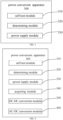
- FIG. 3 shows a schematic block diagram of a power conversion apparatus 300 of embodiments of the present application.
- the power conversion apparatus 300 includes:
- the power output by the power supply module 330 can meet the demand of different vehicle types, a boosting or step-down circuit can also integrated into the power conversion apparatus, to realize the match with the charging pile and the power battery.
- the power supply control device which is the power conversion apparatus of embodiments of the present application can be integrated in the power conversion apparatus, namely, the power supply control device is the power conversion apparatus, it can also be independent of the power conversion apparatus, and separately provides the working power for the power conversion apparatus.
- the determining module 320 is specifically configured to: determine the power supply priority order of the charging power and the power battery, on the basis of electric quantity of the power battery.
- the determining module 320 is specifically configured to: determine that the power supply priority of the power battery is higher than the power supply priority of the charging power, under the condition that the electric quantity of the power battery is higher than a first threshold; or, determine that the power supply priority of the power battery is less than the power supply priority of the charging power, under the condition that the electric quantity of the power battery is less than or equal to the first threshold.
- the power conversion apparatus 300 also includes: an acquiring module 340, configured to: acquire the auxiliary power when determining the power conversion apparatus is in a normal working mode, the normal working mode is a working mode in which the charging pile, the power conversion apparatus and the power battery are interconnected.
- an acquiring module 340 configured to: acquire the auxiliary power when determining the power conversion apparatus is in a normal working mode, the normal working mode is a working mode in which the charging pile, the power conversion apparatus and the power battery are interconnected.
- the acquiring module 340 is specifically configured to: acquire the auxiliary power when receiving a connection success information sent by the charging pile.
- the power conversion apparatus 300 also includes: a direct current to direct current (DC-DC) module 350, configured to: convert the charging power and/or the power battery into a working power of the power conversion apparatus before the power conversion apparatus determines the one of the charging power of the charging pile and the power battery with a higher power supply priority as the current working power of the power conversion apparatus.
- DC-DC direct current to direct current
- the power conversion apparatus 300 can include one DC-DC module 350, in other words, the charging power and the power battery can share one DC-DC module 350; the power conversion apparatus 300 can also include two DC-DC modules 250, in other words, the charging power and the power battery respectively use one DC-DC module 350.
- the power supply module 330 is also configured to: in an off-line debugging mode of the power conversion apparatus, determine a standard grid or an external direct current power as the current working power of the power conversion apparatus.
- the power conversion apparatus 300 also includes: An alternating current to direct current (AC-DC) module 360, configured to convert the standard grid into the working power of the power conversion apparatus before the power conversion apparatus determines the standard grid as the working power of the power conversion apparatus.
- AC-DC alternating current to direct current
- the power conversion apparatus 300 is configured to convert a direct current output by the charging power into a pulse current and charge to the power battery.
- FIG. 5 shows a schematic block diagram of a power supply control system
- the power supply control system includes a charging pile 510, a BMS 520, a power unit 50, a control unit 540, a power supply module 550, a DC-DC module 560 and a AC-DC module 570, where, the power unit 530 and the control unit 540 constitute a power conversion apparatus, optionally, the power supply module 550, the DC-DC module 560 and the AC-DC module 570 can also be integrated into the power conversion apparatus.
- the power unit 530 and the control unit 540 constitute a power conversion apparatus
- the power supply module 550, the DC-DC module 560 and the AC-DC module 570 can also be integrated into the power conversion apparatus.
- the standard grid after being converted by AC-DC module 570 is output by the power supply module 350, and the auxiliary power A+/A- and external direct current power are directly output by the power supply module 550, the charging power DC+/DC- and the BMS are required to be output by the power supply module 550 after the DC-DC conversion.
- the power supply module 550 can correspond to the power supply module 330, the determining module 320 and the acquiring module 340 in the above-mentioned power conversion apparatus 300, while the self-test module 310 in the power conversion apparatus 300 can be implemented by the control unit 540 and the power unit 530.
- FIG. 6 shows a schematic block diagram of a power conversion apparatus 600 of another embodiment of the present application.
- a power conversion apparatus 600 includes a memory 610 and a processor 620, where, the memory 610 is configured for storing an instruction, the processor 620 is configured for reading the instruction and executing the method of aforementioned various embodiments of present application based on the instruction.
- Embodiments of the present application also provide a readable storage medium for storing a computer program, the computer program is configured for executing the method of aforementioned various embodiments of the present application.
- the disclosed system, device and method can be implemented in other manner.
- the device embodiments described above are only schematic, for example, the division of the unit is merely a division of logic function, the actual implementation can have additional division method, for example multiple units or assemblies can be combined or can be integrate into another system, or some features can be omitted or not implemented.
- the mutual interconnection or direct interconnection or communication connect can be indirect interconnection or communication connection via some interfaces, devices or units, they can be electric, mechanical or in other forms.
- the unit illustrated as a separate component may be or may on be physically separated, the components shown as a unit may be or may not be a physical unit, namely can be located in one place, or can be distributed to multiple network units. A portion of or all of the units can be chosen according to actual demand to accomplish the purpose of this embodiment.
- each functional unit in each embodiment of the present application can be integrated in one processing unit, they can also be separate physical presence of each unit, two or more units can also be integrated into one unit.
- the function is implemented in manner of software and sold or used as an independent product, it can be stored in one computer readable storage medium.
- the technical solution of present application can be essentially or the portion which contributes the prior art or a portion of the technical solution can be embodied in software product
- the computer software product is stored in one storage medium, including several instructions for one computer apparatus (it may be a personal computer, a server, or a network apparatus, etc.) executing all of or a portion of the steps of method in each embodiment of the present application.
- the aforementioned storage medium includes: USB flash drive, mobile hard disk drive, read-only memory (ROM), random access memory (RAM), disk or optical disk or several media which can store a program code.
Landscapes
- Engineering & Computer Science (AREA)
- Power Engineering (AREA)
- Transportation (AREA)
- Mechanical Engineering (AREA)
- Charge And Discharge Circuits For Batteries Or The Like (AREA)
- Dc-Dc Converters (AREA)
Claims (15)
- Procédé de commande d'alimentation en puissance (200) pour un appareil de conversion de puissance, dans lequel l'appareil de conversion de puissance comprend une unité de commande et une unité de puissance, l'unité de puissance est configurée pour convertir un courant continu émis en sortie par une puissance de charge d'un chargeur selon un courant pulsé et pour charger une batterie de puissance, et l'unité de commande est configurée pour commander l'unité de puissance pour mettre en œuvre la conversion de puissance, le procédé comprend :la mise en œuvre (S210) d'un autotest d'alimentation en puissance avec une puissance auxiliaire du chargeur par l'appareil de conversion de puissance ;la détermination (S220) de l'ordre de priorité d'alimentation en puissance d'une puissance de charge du chargeur et de la batterie de puissance sur la base d'un paramètre d'état de la batterie de puissance, sous la condition consistant en ce que l'autotest de l'appareil de conversion de puissance est réussi ;la détermination (S230) de la puissance de charge du chargeur ou de la batterie de puissance selon celle qui présente une priorité d'alimentation en puissance plus élevée en tant que puissance de travail courante de l'appareil de conversion de puissance par l'appareil de conversion de puissance, dans lequel la puissance de travail est une alimentation en puissance pour l'unité de commande ;l'alimentation en puissance de l'unité de commande conformément à la puissance de travail courante.
- Procédé de commande d'alimentation en puissance selon la revendication 1, dans lequel la détermination (S230) de l'ordre de priorité d'alimentation en puissance de la puissance de charge et de la batterie de puissance sur la base du paramètre d'état de la batterie de puissance comprend
la détermination de l'ordre de priorité d'alimentation en puissance de la puissance de charge et de la batterie de puissance par l'appareil de conversion de puissance sur la base d'une quantité électrique de la batterie de puissance. - Procédé de commande d'alimentation en puissance selon la revendication 2, dans lequel la détermination de l'ordre de priorité d'alimentation en puissance de la puissance de charge et de la batterie de puissance par l'appareil de conversion de puissance sur la base de la quantité électrique de la batterie de puissance comprend :
la détermination du fait que la priorité d'alimentation en puissance de la batterie de puissance est supérieure à la priorité d'alimentation en puissance de la puissance de charge par l'appareil de conversion de puissance, sous la condition consistant en ce que la quantité électrique de la batterie de puissance est supérieure à un premier seuil ; ou la détermination du fait que la priorité d'alimentation en puissance de la batterie de puissance est inférieure à la priorité d'alimentation en puissance de la puissance de charge par l'appareil de conversion de puissance, sous la condition consistant en ce que la quantité électrique de la batterie de puissance est inférieure ou égale au premier seuil. - Procédé de commande d'alimentation en puissance selon l'une quelconque des revendications 1 à 3, dans lequel le procédé comprend en outre :
l'acquisition de la puissance auxiliaire par l'appareil de conversion de puissance lorsqu'il est déterminé que l'appareil de conversion de puissance est dans un mode de fonctionnement normal, le mode de fonctionnement normal est un mode de fonctionnement dans lequel le chargeur, l'appareil de conversion de puissance et la batterie de puissance sont interconnectés. - Procédé de commande d'alimentation en puissance selon la revendication 4, dans lequel l'acquisition de la puissance auxiliaire par l'appareil de conversion de puissance lors de la détermination du fait que l'appareil de conversion de puissance est dans le mode de fonctionnement normal, l'appareil de conversion de puissance accède à la puissance auxiliaire, comprenant :
l'acquisition de la puissance auxiliaire par l'appareil de conversion de puissance lors de la réception d'une information de succès de connexion envoyée par le chargeur. - Procédé de commande d'alimentation en puissance selon l'une quelconque des revendications 1 à 5, dans lequel, avant la détermination de la puissance de charge du chargeur ou de la batterie de puissance selon celle qui présente une priorité d'alimentation en puissance plus élevée en tant que puissance de travail courante de l'appareil de conversion de puissance par l'appareil de conversion de puissance, le procédé comprend en outre :
la conversion de la puissance de charge et/ou de la batterie de puissance selon une puissance de travail de l'appareil de conversion de puissance par l'appareil de conversion de puissance. - Procédé de commande d'alimentation en puissance selon l'une quelconque des revendications 1 à 6, dans lequel le procédé comprend en outre :
dans un mode de débogage hors ligne de l'appareil de conversion de puissance, la détermination d'un réseau standard ou d'une puissance en courant continu externe en tant que puissance de travail courante de l'appareil de conversion de puissance par l'appareil de conversion de puissance. - Procédé de commande d'alimentation en puissance selon la revendication 7, dans lequel, avant la détermination du réseau standard en tant que puissance de travail de l'appareil de conversion de puissance par l'appareil de conversion de puissance, le procédé comprend en outre :
la conversion du réseau standard selon la puissance de travail de l'appareil de conversion de puissance par l'appareil de conversion de puissance. - Procédé de commande d'alimentation en puissance selon l'une quelconque des revendications 1 à 8, dans lequel l'appareil de conversion de puissance est configuré pour convertir un courant continu émis en sortie par la puissance de charge selon un courant pulsé et pour charger la batterie de puissance.
- Appareil de conversion de puissance (300), dans lequel l'appareil de conversion de puissance est configuré pour mettre en œuvre une conversion de puissance entre un chargeur et une batterie de puissance, l'appareil de conversion de puissance comprend :une unité de puissance, configurée pour convertir un courant continu émis en sortie par une puissance de charge d'une pile de charge selon un courant pulsé et pour charger une batterie de puissance ;une unité de commande, configurée pour commander l'unité de puissance pour mettre en œuvre la conversion de puissance ; un module d'autotest (310), configuré pour mettre en œuvre un autotest d'alimentation en puissance en utilisant une puissance auxiliaire du chargeur ;un module de détermination (320), configuré pour déterminer l'ordre de priorité d'alimentation d'une puissance de charge du chargeur et de la batterie de puissance sur la base d'un paramètre d'état de la batterie de puissance, sous la condition consistant en ce que l'autotest de l'appareil de conversion de puissance est réussi ;un module d'alimentation en puissance (330), configuré pour déterminer la puissance de charge du chargeur ou la batterie de puissance selon celle qui présente une priorité d'alimentation en puissance plus élevée en tant que puissance de travail courante de l'appareil de conversion de puissance, dans lequel la puissance de travail est une alimentation en puissance pour l'unité de commande ;le module d'alimentation en puissance (330) est configuré pour alimenter en puissance l'unité de commande conformément à la puissance de travail courante.
- Appareil de conversion de puissance (300) selon la revendication 10, dans lequel l'appareil de conversion de puissance comprend en outre :
un module d'acquisition (340), configuré pour acquérir la puissance auxiliaire lors de la détermination du fait que l'appareil de conversion de puissance est dans un mode de fonctionnement normal, le mode de fonctionnement normal est un mode de fonctionnement dans lequel le chargeur, l'appareil de conversion de puissance et la batterie de puissance sont interconnectés. - Appareil de conversion de puissance (300) selon la revendication 11, dans lequel le module d'acquisition (340) est spécifiquement configuré pour :
acquérir la puissance auxiliaire lors de la réception d'une information de succès de connexion envoyée par le chargeur. - Appareil de conversion de puissance (300) selon l'une quelconque des revendications 10 à 12, dans lequel l'appareil de conversion de puissance comprend en outre :
un module courant continu à courant continu, DC-DC, (350), configuré pour convertir la puissance de charge et/ou la batterie de puissance selon une puissance de travail de l'appareil de conversion de puissance avant que l'appareil de conversion de puissance ne détermine la puissance de charge du chargeur ou la batterie de puissance selon celle qui présente la priorité d'alimentation en puissance plus élevée en tant que puissance de travail courante de l'appareil de conversion de puissance. - Appareil de conversion de puissance (300) selon l'une quelconque des revendications 10 à 13, dans lequel le module d'alimentation en puissance (330) est en outre configuré pour :
dans un mode de débogage hors ligne de l'appareil de conversion de puissance, déterminer un réseau standard ou une puissance en courant continu externe en tant que puissance de travail courante de l'appareil de conversion de puissance. - Appareil de conversion de puissance (600), comprenant une mémoire (610) et un processeur (620), dans lequel la mémoire (610) stocke des instructions qui, lorsqu'elles sont exécutées par le processeur, forcent l'appareil de conversion de puissance (600) à mettre en œuvre le procédé selon l'une quelconque des revendications 1 à 9.
Priority Applications (1)
| Application Number | Priority Date | Filing Date | Title |
|---|---|---|---|
| HUE21810517A HUE069223T2 (hu) | 2021-01-28 | 2021-01-28 | Energiaellátás-vezérlési eljárás energiaátalakító eszközhöz, valamint energiaátalakító eszköz |
Applications Claiming Priority (1)
| Application Number | Priority Date | Filing Date | Title |
|---|---|---|---|
| PCT/CN2021/074179 WO2022160187A1 (fr) | 2021-01-28 | 2021-01-28 | Procédé de commande d'alimentation électrique pour dispositif de conversion de puissance, et dispositif de conversion de puissance |
Publications (3)
| Publication Number | Publication Date |
|---|---|
| EP4064536A1 EP4064536A1 (fr) | 2022-09-28 |
| EP4064536A4 EP4064536A4 (fr) | 2022-09-28 |
| EP4064536B1 true EP4064536B1 (fr) | 2024-10-16 |
Family
ID=82496116
Family Applications (1)
| Application Number | Title | Priority Date | Filing Date |
|---|---|---|---|
| EP21810517.9A Active EP4064536B1 (fr) | 2021-01-28 | 2021-01-28 | Procédé de commande d'alimentation électrique pour dispositif de conversion de puissance, et dispositif de conversion de puissance |
Country Status (7)
| Country | Link |
|---|---|
| US (1) | US20220239135A1 (fr) |
| EP (1) | EP4064536B1 (fr) |
| JP (1) | JP7326491B2 (fr) |
| KR (1) | KR102644605B1 (fr) |
| CN (1) | CN116250158A (fr) |
| HU (1) | HUE069223T2 (fr) |
| WO (1) | WO2022160187A1 (fr) |
Families Citing this family (9)
| Publication number | Priority date | Publication date | Assignee | Title |
|---|---|---|---|---|
| KR102893180B1 (ko) * | 2021-01-28 | 2025-12-01 | 컨템포러리 엠퍼렉스 테크놀로지 (홍콩) 리미티드 | 충전 방법, 전원 배터리의 배터리 관리 시스템 및 충전 파일 |
| KR102644606B1 (ko) * | 2021-01-28 | 2024-03-08 | 컨템포러리 엠퍼렉스 테크놀로지 씨오., 리미티드 | 충전 방법 및 전력 변환 장치 |
| KR102726227B1 (ko) * | 2021-01-28 | 2024-11-05 | 컨템포러리 엠퍼렉스 테크놀로지 (홍콩) 리미티드 | 충전 방법, 전원 배터리의 배터리 관리 시스템 및 충전 파일 |
| WO2022261910A1 (fr) * | 2021-06-17 | 2022-12-22 | 宁德时代新能源科技股份有限公司 | Procédé et appareil de commande de charge, système de gestion de batterie et support de stockage lisible |
| WO2023004712A1 (fr) * | 2021-07-29 | 2023-02-02 | 宁德时代新能源科技股份有限公司 | Appareil de charge et de décharge, procédé de charge de batterie et système de charge et de décharge |
| CN116452198B (zh) * | 2023-06-14 | 2023-09-01 | 南京能可瑞科技有限公司 | 一种充电桩离线授权和计费方法及系统 |
| CN119519342A (zh) * | 2023-08-25 | 2025-02-25 | 台达电子工业股份有限公司 | 供电系统、电源转换器及电力转换方法 |
| EP4635786A1 (fr) * | 2024-04-18 | 2025-10-22 | Shell Internationale Research Maatschappij B.V. | Système et procédé de charge de véhicule électrique |
| CN119093574A (zh) * | 2024-11-11 | 2024-12-06 | 上海融和智电新能源有限公司 | 放电切换充电枪不断电系统、方法、介质、程序产品及终端 |
Family Cites Families (16)
| Publication number | Priority date | Publication date | Assignee | Title |
|---|---|---|---|---|
| JPH0832160B2 (ja) * | 1990-01-31 | 1996-03-27 | 三菱電機株式会社 | パルス電源装置 |
| US6175311B1 (en) * | 2000-02-17 | 2001-01-16 | Digipower Manufacturing Inc. | On-line UPS controllable from far end |
| US7570020B1 (en) * | 2005-09-30 | 2009-08-04 | National Semiconductor Corporation | Apparatus and method for magnetic charger IC for batteries with recycling of the LC filter for re-use as a battery step-down converter |
| CN103117585B (zh) * | 2011-11-16 | 2016-02-10 | 长丰集团有限责任公司 | 一种电动汽车混合储能充电系统 |
| CN102780249A (zh) * | 2012-08-17 | 2012-11-14 | 天津清源电动车辆有限责任公司 | 利用超级电容实现电动汽车快速充电的方法 |
| US11126242B2 (en) * | 2013-10-28 | 2021-09-21 | Virtual Power Systems, Inc. | Time varying power management within datacenters |
| JP6204902B2 (ja) * | 2014-11-19 | 2017-09-27 | 三菱重工業株式会社 | 充放電制御装置及びこれを有する電池システム |
| CN205039200U (zh) * | 2015-10-12 | 2016-02-17 | 北京新能源汽车股份有限公司 | 动力电池系统及具有其的车辆 |
| KR101734210B1 (ko) * | 2015-10-29 | 2017-05-11 | 포항공과대학교 산학협력단 | 양방향 직류-직류 컨버터 |
| CN107317365A (zh) * | 2016-04-27 | 2017-11-03 | 法乐第(北京)网络科技有限公司 | 充电装置、充电方法以及车辆 |
| JP7044500B2 (ja) * | 2016-09-12 | 2022-03-30 | 積水化学工業株式会社 | 電力供給システム |
| CN108111032A (zh) * | 2016-11-25 | 2018-06-01 | 台达电子工业股份有限公司 | 功率变换装置与功率变换方法 |
| CN107264308B (zh) * | 2017-05-31 | 2020-03-06 | 北京新能源汽车股份有限公司 | 一种车载供电系统及汽车 |
| CN207368734U (zh) * | 2017-08-24 | 2018-05-15 | 深圳市沃特玛电池有限公司 | 一种光伏储能充电系统 |
| US11159084B2 (en) * | 2018-12-14 | 2021-10-26 | Infineon Technologies Ag | Protection circuit with a cut-off switch for power systems |
| US11135934B2 (en) * | 2019-09-06 | 2021-10-05 | Nio Usa, Inc. | Vehicle power devices, systems, and methods for sleep mode |
-
2021
- 2021-01-28 JP JP2021572482A patent/JP7326491B2/ja active Active
- 2021-01-28 EP EP21810517.9A patent/EP4064536B1/fr active Active
- 2021-01-28 CN CN202180060171.1A patent/CN116250158A/zh active Pending
- 2021-01-28 HU HUE21810517A patent/HUE069223T2/hu unknown
- 2021-01-28 WO PCT/CN2021/074179 patent/WO2022160187A1/fr not_active Ceased
- 2021-01-28 KR KR1020217040050A patent/KR102644605B1/ko active Active
- 2021-12-02 US US17/540,436 patent/US20220239135A1/en active Pending
Also Published As
| Publication number | Publication date |
|---|---|
| KR102644605B1 (ko) | 2024-03-08 |
| HUE069223T2 (hu) | 2025-02-28 |
| JP2023514881A (ja) | 2023-04-12 |
| KR20220110666A (ko) | 2022-08-09 |
| CN116250158A (zh) | 2023-06-09 |
| JP7326491B2 (ja) | 2023-08-15 |
| EP4064536A1 (fr) | 2022-09-28 |
| WO2022160187A1 (fr) | 2022-08-04 |
| US20220239135A1 (en) | 2022-07-28 |
| EP4064536A4 (fr) | 2022-09-28 |
Similar Documents
| Publication | Publication Date | Title |
|---|---|---|
| EP4064536B1 (fr) | Procédé de commande d'alimentation électrique pour dispositif de conversion de puissance, et dispositif de conversion de puissance | |
| KR102801326B1 (ko) | 배터리 충전 방법 및 충방전 장치 | |
| EP4068561B1 (fr) | Procédé de charge et dispositif de conversion de puissance | |
| KR102893181B1 (ko) | 배터리 충전 방법, 배터리 관리 시스템 및 충방전 장치 | |
| KR102534561B1 (ko) | 충방전 장치, 배터리 충방전 방법 및 충방전 시스템 | |
| KR20130111191A (ko) | 배터리 특성 자동 인식 시스템, 이에 적용되는 배터리 정보 저장 장치 및 이를 이용한 배터리 관리 장치의 최적화 방법 | |
| US12230987B2 (en) | Power conversion device | |
| US20220239120A1 (en) | Pre-charging method of power conversion device and power conversion device | |
| CN115836424B (zh) | 充电的方法、动力电池的电池管理系统和充电桩 | |
| KR102644604B1 (ko) | 충방전 장치, 배터리 충전 방법 및 충방전 시스템 | |
| WO2024139742A1 (fr) | Groupe de batteries, système de stockage d'énergie, système d'alimentation sans coupure et véhicule électrique | |
| KR102645452B1 (ko) | 충방전 장치, 배터리 충전 방법 및 충방전 시스템 | |
| KR101658865B1 (ko) | 통신 에러로부터 잘못된 제어 알고리즘의 수행을 방지하는 배터리 관리 장치 | |
| KR101633834B1 (ko) | 전원 안전 차단 기능을 가진 배터리 관리 시스템 및 그 제어 방법 | |
| CN205725051U (zh) | 一种实现电池扩容的装置 | |
| CN114362303B (zh) | 换电柜充电方法、装置、电子设备及存储介质 | |
| CN114498890B (zh) | 多电池的主电池切换方法、装置、设备、系统及存储介质 | |
| CN105896724A (zh) | 智能型发电机组负荷控制方法及系统 | |
| CN118810442A (zh) | 一种铅酸电池管理系统及其控制方法 | |
| CN119726994A (zh) | 电池充电方法及系统 |
Legal Events
| Date | Code | Title | Description |
|---|---|---|---|
| STAA | Information on the status of an ep patent application or granted ep patent |
Free format text: STATUS: UNKNOWN |
|
| STAA | Information on the status of an ep patent application or granted ep patent |
Free format text: STATUS: THE INTERNATIONAL PUBLICATION HAS BEEN MADE |
|
| PUAI | Public reference made under article 153(3) epc to a published international application that has entered the european phase |
Free format text: ORIGINAL CODE: 0009012 |
|
| STAA | Information on the status of an ep patent application or granted ep patent |
Free format text: STATUS: REQUEST FOR EXAMINATION WAS MADE |
|
| 17P | Request for examination filed |
Effective date: 20211201 |
|
| A4 | Supplementary search report drawn up and despatched |
Effective date: 20220629 |
|
| AK | Designated contracting states |
Kind code of ref document: A1 Designated state(s): AL AT BE BG CH CY CZ DE DK EE ES FI FR GB GR HR HU IE IS IT LI LT LU LV MC MK MT NL NO PL PT RO RS SE SI SK SM TR |
|
| STAA | Information on the status of an ep patent application or granted ep patent |
Free format text: STATUS: EXAMINATION IS IN PROGRESS |
|
| 17Q | First examination report despatched |
Effective date: 20231123 |
|
| REG | Reference to a national code |
Ref country code: DE Ref legal event code: R079 Ref document number: 602021020444 Country of ref document: DE Free format text: PREVIOUS MAIN CLASS: H02M0001000000 Ipc: H02M0001360000 |
|
| DAV | Request for validation of the european patent (deleted) | ||
| DAX | Request for extension of the european patent (deleted) | ||
| RIC1 | Information provided on ipc code assigned before grant |
Ipc: B60L 53/30 20190101ALI20240424BHEP Ipc: B60L 53/20 20190101ALI20240424BHEP Ipc: B60L 53/31 20190101ALI20240424BHEP Ipc: B60L 53/22 20190101ALI20240424BHEP Ipc: B60L 53/10 20190101ALI20240424BHEP Ipc: H02J 7/06 20060101ALI20240424BHEP Ipc: H02M 1/36 20070101AFI20240424BHEP |
|
| GRAP | Despatch of communication of intention to grant a patent |
Free format text: ORIGINAL CODE: EPIDOSNIGR1 |
|
| STAA | Information on the status of an ep patent application or granted ep patent |
Free format text: STATUS: GRANT OF PATENT IS INTENDED |
|
| INTG | Intention to grant announced |
Effective date: 20240611 |
|
| GRAS | Grant fee paid |
Free format text: ORIGINAL CODE: EPIDOSNIGR3 |
|
| GRAA | (expected) grant |
Free format text: ORIGINAL CODE: 0009210 |
|
| STAA | Information on the status of an ep patent application or granted ep patent |
Free format text: STATUS: THE PATENT HAS BEEN GRANTED |
|
| RAP1 | Party data changed (applicant data changed or rights of an application transferred) |
Owner name: CONTEMPORARY AMPEREX TECHNOLOGY(HONG KONG) LIMITED |
|
| AK | Designated contracting states |
Kind code of ref document: B1 Designated state(s): AL AT BE BG CH CY CZ DE DK EE ES FI FR GB GR HR HU IE IS IT LI LT LU LV MC MK MT NL NO PL PT RO RS SE SI SK SM TR |
|
| REG | Reference to a national code |
Ref country code: GB Ref legal event code: FG4D |
|
| REG | Reference to a national code |
Ref country code: CH Ref legal event code: EP Ref country code: DE Ref legal event code: R096 Ref document number: 602021020444 Country of ref document: DE |
|
| REG | Reference to a national code |
Ref country code: IE Ref legal event code: FG4D |
|
| REG | Reference to a national code |
Ref country code: NL Ref legal event code: FP |
|
| REG | Reference to a national code |
Ref country code: LT Ref legal event code: MG9D |
|
| P01 | Opt-out of the competence of the unified patent court (upc) registered |
Free format text: CASE NUMBER: APP_1257/2025 Effective date: 20250109 |
|
| REG | Reference to a national code |
Ref country code: HU Ref legal event code: AG4A Ref document number: E069223 Country of ref document: HU |
|
| REG | Reference to a national code |
Ref country code: AT Ref legal event code: MK05 Ref document number: 1733753 Country of ref document: AT Kind code of ref document: T Effective date: 20241016 |
|
| PG25 | Lapsed in a contracting state [announced via postgrant information from national office to epo] |
Ref country code: IS Free format text: LAPSE BECAUSE OF FAILURE TO SUBMIT A TRANSLATION OF THE DESCRIPTION OR TO PAY THE FEE WITHIN THE PRESCRIBED TIME-LIMIT Effective date: 20250216 Ref country code: PT Free format text: LAPSE BECAUSE OF FAILURE TO SUBMIT A TRANSLATION OF THE DESCRIPTION OR TO PAY THE FEE WITHIN THE PRESCRIBED TIME-LIMIT Effective date: 20250217 Ref country code: HR Free format text: LAPSE BECAUSE OF FAILURE TO SUBMIT A TRANSLATION OF THE DESCRIPTION OR TO PAY THE FEE WITHIN THE PRESCRIBED TIME-LIMIT Effective date: 20241016 |
|
| PG25 | Lapsed in a contracting state [announced via postgrant information from national office to epo] |
Ref country code: FI Free format text: LAPSE BECAUSE OF FAILURE TO SUBMIT A TRANSLATION OF THE DESCRIPTION OR TO PAY THE FEE WITHIN THE PRESCRIBED TIME-LIMIT Effective date: 20241016 |
|
| PG25 | Lapsed in a contracting state [announced via postgrant information from national office to epo] |
Ref country code: BG Free format text: LAPSE BECAUSE OF FAILURE TO SUBMIT A TRANSLATION OF THE DESCRIPTION OR TO PAY THE FEE WITHIN THE PRESCRIBED TIME-LIMIT Effective date: 20241016 |
|
| PG25 | Lapsed in a contracting state [announced via postgrant information from national office to epo] |
Ref country code: ES Free format text: LAPSE BECAUSE OF FAILURE TO SUBMIT A TRANSLATION OF THE DESCRIPTION OR TO PAY THE FEE WITHIN THE PRESCRIBED TIME-LIMIT Effective date: 20241016 |
|
| PG25 | Lapsed in a contracting state [announced via postgrant information from national office to epo] |
Ref country code: NO Free format text: LAPSE BECAUSE OF FAILURE TO SUBMIT A TRANSLATION OF THE DESCRIPTION OR TO PAY THE FEE WITHIN THE PRESCRIBED TIME-LIMIT Effective date: 20250116 |
|
| PG25 | Lapsed in a contracting state [announced via postgrant information from national office to epo] |
Ref country code: GR Free format text: LAPSE BECAUSE OF FAILURE TO SUBMIT A TRANSLATION OF THE DESCRIPTION OR TO PAY THE FEE WITHIN THE PRESCRIBED TIME-LIMIT Effective date: 20250117 Ref country code: AT Free format text: LAPSE BECAUSE OF FAILURE TO SUBMIT A TRANSLATION OF THE DESCRIPTION OR TO PAY THE FEE WITHIN THE PRESCRIBED TIME-LIMIT Effective date: 20241016 Ref country code: LV Free format text: LAPSE BECAUSE OF FAILURE TO SUBMIT A TRANSLATION OF THE DESCRIPTION OR TO PAY THE FEE WITHIN THE PRESCRIBED TIME-LIMIT Effective date: 20241016 |
|
| PG25 | Lapsed in a contracting state [announced via postgrant information from national office to epo] |
Ref country code: PL Free format text: LAPSE BECAUSE OF FAILURE TO SUBMIT A TRANSLATION OF THE DESCRIPTION OR TO PAY THE FEE WITHIN THE PRESCRIBED TIME-LIMIT Effective date: 20241016 |
|
| PG25 | Lapsed in a contracting state [announced via postgrant information from national office to epo] |
Ref country code: RS Free format text: LAPSE BECAUSE OF FAILURE TO SUBMIT A TRANSLATION OF THE DESCRIPTION OR TO PAY THE FEE WITHIN THE PRESCRIBED TIME-LIMIT Effective date: 20250116 |
|
| PG25 | Lapsed in a contracting state [announced via postgrant information from national office to epo] |
Ref country code: SM Free format text: LAPSE BECAUSE OF FAILURE TO SUBMIT A TRANSLATION OF THE DESCRIPTION OR TO PAY THE FEE WITHIN THE PRESCRIBED TIME-LIMIT Effective date: 20241016 |
|
| PG25 | Lapsed in a contracting state [announced via postgrant information from national office to epo] |
Ref country code: DK Free format text: LAPSE BECAUSE OF FAILURE TO SUBMIT A TRANSLATION OF THE DESCRIPTION OR TO PAY THE FEE WITHIN THE PRESCRIBED TIME-LIMIT Effective date: 20241016 |
|
| REG | Reference to a national code |
Ref country code: DE Ref legal event code: R097 Ref document number: 602021020444 Country of ref document: DE |
|
| PG25 | Lapsed in a contracting state [announced via postgrant information from national office to epo] |
Ref country code: EE Free format text: LAPSE BECAUSE OF FAILURE TO SUBMIT A TRANSLATION OF THE DESCRIPTION OR TO PAY THE FEE WITHIN THE PRESCRIBED TIME-LIMIT Effective date: 20241016 |
|
| PG25 | Lapsed in a contracting state [announced via postgrant information from national office to epo] |
Ref country code: RO Free format text: LAPSE BECAUSE OF FAILURE TO SUBMIT A TRANSLATION OF THE DESCRIPTION OR TO PAY THE FEE WITHIN THE PRESCRIBED TIME-LIMIT Effective date: 20241016 |
|
| PG25 | Lapsed in a contracting state [announced via postgrant information from national office to epo] |
Ref country code: SK Free format text: LAPSE BECAUSE OF FAILURE TO SUBMIT A TRANSLATION OF THE DESCRIPTION OR TO PAY THE FEE WITHIN THE PRESCRIBED TIME-LIMIT Effective date: 20241016 |
|
| PG25 | Lapsed in a contracting state [announced via postgrant information from national office to epo] |
Ref country code: CZ Free format text: LAPSE BECAUSE OF FAILURE TO SUBMIT A TRANSLATION OF THE DESCRIPTION OR TO PAY THE FEE WITHIN THE PRESCRIBED TIME-LIMIT Effective date: 20241016 |
|
| PLBE | No opposition filed within time limit |
Free format text: ORIGINAL CODE: 0009261 |
|
| STAA | Information on the status of an ep patent application or granted ep patent |
Free format text: STATUS: NO OPPOSITION FILED WITHIN TIME LIMIT |
|
| REG | Reference to a national code |
Ref country code: CH Ref legal event code: PL |
|
| PG25 | Lapsed in a contracting state [announced via postgrant information from national office to epo] |
Ref country code: SE Free format text: LAPSE BECAUSE OF FAILURE TO SUBMIT A TRANSLATION OF THE DESCRIPTION OR TO PAY THE FEE WITHIN THE PRESCRIBED TIME-LIMIT Effective date: 20241016 |
|
| PG25 | Lapsed in a contracting state [announced via postgrant information from national office to epo] |
Ref country code: MC Free format text: LAPSE BECAUSE OF FAILURE TO SUBMIT A TRANSLATION OF THE DESCRIPTION OR TO PAY THE FEE WITHIN THE PRESCRIBED TIME-LIMIT Effective date: 20241016 Ref country code: LU Free format text: LAPSE BECAUSE OF NON-PAYMENT OF DUE FEES Effective date: 20250128 |
|
| 26N | No opposition filed |
Effective date: 20250717 |
|
| PG25 | Lapsed in a contracting state [announced via postgrant information from national office to epo] |
Ref country code: BE Free format text: LAPSE BECAUSE OF NON-PAYMENT OF DUE FEES Effective date: 20250131 |
|
| PG25 | Lapsed in a contracting state [announced via postgrant information from national office to epo] |
Ref country code: CH Free format text: LAPSE BECAUSE OF NON-PAYMENT OF DUE FEES Effective date: 20250131 |
|
| REG | Reference to a national code |
Ref country code: BE Ref legal event code: MM Effective date: 20250131 |
|
| PG25 | Lapsed in a contracting state [announced via postgrant information from national office to epo] |
Ref country code: IE Free format text: LAPSE BECAUSE OF NON-PAYMENT OF DUE FEES Effective date: 20250128 |
|
| PGFP | Annual fee paid to national office [announced via postgrant information from national office to epo] |
Ref country code: NL Payment date: 20260128 Year of fee payment: 6 |
|
| PGFP | Annual fee paid to national office [announced via postgrant information from national office to epo] |
Ref country code: HU Payment date: 20251229 Year of fee payment: 6 |
|
| PGFP | Annual fee paid to national office [announced via postgrant information from national office to epo] |
Ref country code: GB Payment date: 20260123 Year of fee payment: 6 |
|
| PGFP | Annual fee paid to national office [announced via postgrant information from national office to epo] |
Ref country code: DE Payment date: 20260126 Year of fee payment: 6 |
|
| PGFP | Annual fee paid to national office [announced via postgrant information from national office to epo] |
Ref country code: IT Payment date: 20260126 Year of fee payment: 6 |
|
| PGFP | Annual fee paid to national office [announced via postgrant information from national office to epo] |
Ref country code: FR Payment date: 20260129 Year of fee payment: 6 |