EP4064549B1 - Installation de transport sous forme d'un moteur linéaire à stator long et procédé de fonctionnement de ladite installation de transport - Google Patents
Installation de transport sous forme d'un moteur linéaire à stator long et procédé de fonctionnement de ladite installation de transport Download PDFInfo
- Publication number
- EP4064549B1 EP4064549B1 EP22161524.8A EP22161524A EP4064549B1 EP 4064549 B1 EP4064549 B1 EP 4064549B1 EP 22161524 A EP22161524 A EP 22161524A EP 4064549 B1 EP4064549 B1 EP 4064549B1
- Authority
- EP
- European Patent Office
- Prior art keywords
- error
- transport unit
- stator
- area
- transport
- Prior art date
- Legal status (The legal status is an assumption and is not a legal conclusion. Google has not performed a legal analysis and makes no representation as to the accuracy of the status listed.)
- Active
Links
Images



Classifications
-
- B—PERFORMING OPERATIONS; TRANSPORTING
- B65—CONVEYING; PACKING; STORING; HANDLING THIN OR FILAMENTARY MATERIAL
- B65G—TRANSPORT OR STORAGE DEVICES, e.g. CONVEYORS FOR LOADING OR TIPPING, SHOP CONVEYOR SYSTEMS OR PNEUMATIC TUBE CONVEYORS
- B65G54/00—Non-mechanical conveyors not otherwise provided for
- B65G54/02—Non-mechanical conveyors not otherwise provided for electrostatic, electric, or magnetic
-
- H—ELECTRICITY
- H02—GENERATION; CONVERSION OR DISTRIBUTION OF ELECTRIC POWER
- H02P—CONTROL OR REGULATION OF ELECTRIC MOTORS, ELECTRIC GENERATORS OR DYNAMO-ELECTRIC CONVERTERS; CONTROLLING TRANSFORMERS, REACTORS OR CHOKE COILS
- H02P6/00—Arrangements for controlling synchronous motors or other dynamo-electric motors using electronic commutation dependent on the rotor position; Electronic commutators therefor
- H02P6/006—Controlling linear motors
-
- B—PERFORMING OPERATIONS; TRANSPORTING
- B60—VEHICLES IN GENERAL
- B60L—PROPULSION OF ELECTRICALLY-PROPELLED VEHICLES; SUPPLYING ELECTRIC POWER FOR AUXILIARY EQUIPMENT OF ELECTRICALLY-PROPELLED VEHICLES; ELECTRODYNAMIC BRAKE SYSTEMS FOR VEHICLES IN GENERAL; MAGNETIC SUSPENSION OR LEVITATION FOR VEHICLES; MONITORING OPERATING VARIABLES OF ELECTRICALLY-PROPELLED VEHICLES; ELECTRIC SAFETY DEVICES FOR ELECTRICALLY-PROPELLED VEHICLES
- B60L13/00—Electric propulsion for monorail vehicles, suspension vehicles or rack railways; Magnetic suspension or levitation for vehicles
-
- B—PERFORMING OPERATIONS; TRANSPORTING
- B60—VEHICLES IN GENERAL
- B60L—PROPULSION OF ELECTRICALLY-PROPELLED VEHICLES; SUPPLYING ELECTRIC POWER FOR AUXILIARY EQUIPMENT OF ELECTRICALLY-PROPELLED VEHICLES; ELECTRODYNAMIC BRAKE SYSTEMS FOR VEHICLES IN GENERAL; MAGNETIC SUSPENSION OR LEVITATION FOR VEHICLES; MONITORING OPERATING VARIABLES OF ELECTRICALLY-PROPELLED VEHICLES; ELECTRIC SAFETY DEVICES FOR ELECTRICALLY-PROPELLED VEHICLES
- B60L13/00—Electric propulsion for monorail vehicles, suspension vehicles or rack railways; Magnetic suspension or levitation for vehicles
- B60L13/03—Electric propulsion by linear motors
-
- B—PERFORMING OPERATIONS; TRANSPORTING
- B60—VEHICLES IN GENERAL
- B60L—PROPULSION OF ELECTRICALLY-PROPELLED VEHICLES; SUPPLYING ELECTRIC POWER FOR AUXILIARY EQUIPMENT OF ELECTRICALLY-PROPELLED VEHICLES; ELECTRODYNAMIC BRAKE SYSTEMS FOR VEHICLES IN GENERAL; MAGNETIC SUSPENSION OR LEVITATION FOR VEHICLES; MONITORING OPERATING VARIABLES OF ELECTRICALLY-PROPELLED VEHICLES; ELECTRIC SAFETY DEVICES FOR ELECTRICALLY-PROPELLED VEHICLES
- B60L15/00—Methods, circuits, or devices for controlling the traction-motor speed of electrically-propelled vehicles
-
- B—PERFORMING OPERATIONS; TRANSPORTING
- B60—VEHICLES IN GENERAL
- B60L—PROPULSION OF ELECTRICALLY-PROPELLED VEHICLES; SUPPLYING ELECTRIC POWER FOR AUXILIARY EQUIPMENT OF ELECTRICALLY-PROPELLED VEHICLES; ELECTRODYNAMIC BRAKE SYSTEMS FOR VEHICLES IN GENERAL; MAGNETIC SUSPENSION OR LEVITATION FOR VEHICLES; MONITORING OPERATING VARIABLES OF ELECTRICALLY-PROPELLED VEHICLES; ELECTRIC SAFETY DEVICES FOR ELECTRICALLY-PROPELLED VEHICLES
- B60L3/00—Electric devices on electrically-propelled vehicles for safety purposes; Monitoring operating variables, e.g. speed, deceleration or energy consumption
- B60L3/0023—Detecting, eliminating, remedying or compensating for drive train abnormalities, e.g. failures within the drive train
- B60L3/0061—Detecting, eliminating, remedying or compensating for drive train abnormalities, e.g. failures within the drive train relating to electrical machines
-
- B—PERFORMING OPERATIONS; TRANSPORTING
- B65—CONVEYING; PACKING; STORING; HANDLING THIN OR FILAMENTARY MATERIAL
- B65G—TRANSPORT OR STORAGE DEVICES, e.g. CONVEYORS FOR LOADING OR TIPPING, SHOP CONVEYOR SYSTEMS OR PNEUMATIC TUBE CONVEYORS
- B65G43/00—Control devices, e.g. for safety, warning or fault-correcting
- B65G43/02—Control devices, e.g. for safety, warning or fault-correcting detecting dangerous physical condition of load carriers, e.g. for interrupting the drive in the event of overheating
-
- H—ELECTRICITY
- H02—GENERATION; CONVERSION OR DISTRIBUTION OF ELECTRIC POWER
- H02K—DYNAMO-ELECTRIC MACHINES
- H02K41/00—Propulsion systems in which a rigid body is moved along a path due to dynamo-electric interaction between the body and a magnetic field travelling along the path
- H02K41/02—Linear motors; Sectional motors
-
- H—ELECTRICITY
- H02—GENERATION; CONVERSION OR DISTRIBUTION OF ELECTRIC POWER
- H02K—DYNAMO-ELECTRIC MACHINES
- H02K41/00—Propulsion systems in which a rigid body is moved along a path due to dynamo-electric interaction between the body and a magnetic field travelling along the path
- H02K41/02—Linear motors; Sectional motors
- H02K41/03—Synchronous motors; Motors moving step by step; Reluctance motors
- H02K41/031—Synchronous motors; Motors moving step by step; Reluctance motors of the permanent magnet type
-
- H—ELECTRICITY
- H02—GENERATION; CONVERSION OR DISTRIBUTION OF ELECTRIC POWER
- H02P—CONTROL OR REGULATION OF ELECTRIC MOTORS, ELECTRIC GENERATORS OR DYNAMO-ELECTRIC CONVERTERS; CONTROLLING TRANSFORMERS, REACTORS OR CHOKE COILS
- H02P25/00—Arrangements or methods for the control of AC motors characterised by the kind of AC motor or by structural details
- H02P25/02—Arrangements or methods for the control of AC motors characterised by the kind of AC motor or by structural details characterised by the kind of motor
- H02P25/06—Linear motors
- H02P25/064—Linear motors of the synchronous type
-
- H—ELECTRICITY
- H02—GENERATION; CONVERSION OR DISTRIBUTION OF ELECTRIC POWER
- H02P—CONTROL OR REGULATION OF ELECTRIC MOTORS, ELECTRIC GENERATORS OR DYNAMO-ELECTRIC CONVERTERS; CONTROLLING TRANSFORMERS, REACTORS OR CHOKE COILS
- H02P29/00—Arrangements for regulating or controlling electric motors, appropriate for both AC and DC motors
- H02P29/02—Providing protection against overload without automatic interruption of supply
- H02P29/024—Detecting a fault condition, e.g. short circuit, locked rotor, open circuit or loss of load
-
- H—ELECTRICITY
- H02—GENERATION; CONVERSION OR DISTRIBUTION OF ELECTRIC POWER
- H02P—CONTROL OR REGULATION OF ELECTRIC MOTORS, ELECTRIC GENERATORS OR DYNAMO-ELECTRIC CONVERTERS; CONTROLLING TRANSFORMERS, REACTORS OR CHOKE COILS
- H02P3/00—Arrangements for stopping or slowing electric motors, generators, or dynamo-electric converters
- H02P3/06—Arrangements for stopping or slowing electric motors, generators, or dynamo-electric converters for stopping or slowing an individual dynamo-electric motor or dynamo-electric converter
- H02P3/18—Arrangements for stopping or slowing electric motors, generators, or dynamo-electric converters for stopping or slowing an individual dynamo-electric motor or dynamo-electric converter for stopping or slowing an AC motor
- H02P3/22—Arrangements for stopping or slowing electric motors, generators, or dynamo-electric converters for stopping or slowing an individual dynamo-electric motor or dynamo-electric converter for stopping or slowing an AC motor by short-circuit or resistive braking
-
- H—ELECTRICITY
- H02—GENERATION; CONVERSION OR DISTRIBUTION OF ELECTRIC POWER
- H02P—CONTROL OR REGULATION OF ELECTRIC MOTORS, ELECTRIC GENERATORS OR DYNAMO-ELECTRIC CONVERTERS; CONTROLLING TRANSFORMERS, REACTORS OR CHOKE COILS
- H02P6/00—Arrangements for controlling synchronous motors or other dynamo-electric motors using electronic commutation dependent on the rotor position; Electronic commutators therefor
- H02P6/12—Monitoring commutation; Providing indication of commutation failure
-
- B—PERFORMING OPERATIONS; TRANSPORTING
- B65—CONVEYING; PACKING; STORING; HANDLING THIN OR FILAMENTARY MATERIAL
- B65G—TRANSPORT OR STORAGE DEVICES, e.g. CONVEYORS FOR LOADING OR TIPPING, SHOP CONVEYOR SYSTEMS OR PNEUMATIC TUBE CONVEYORS
- B65G2203/00—Indexing code relating to control or detection of the articles or the load carriers during conveying
- B65G2203/02—Control or detection
- B65G2203/0266—Control or detection relating to the load carrier(s)
- B65G2203/0283—Position of the load carrier
Definitions
- the invention relates to a method for operating a transport system in the form of a long stator linear motor with a stator on which a plurality of magnetic field generating units are arranged and with a plurality of transport units that are simultaneously moved along the stator, wherein in the event of a system fault on a part of the transport system, a fault scope is defined on the stator, wherein the fault scope only includes a part of the stator with the faulty part of the transport system, and the magnetic field generating units in the fault scope are transferred to a predetermined fault state.
- the invention also relates to a correspondingly designed transport system.
- a linear motor has a primary part (stator) and a secondary part (rotor) which is arranged to be movable relative to the primary part.
- Magnetic field generation units are arranged on the primary part and drive magnets on the secondary part, or vice versa.
- the drive magnets are designed either as permanent magnets, electrical coils or short-circuit windings.
- the magnetic field generation units can be designed as drive coils.
- Drive coils are electrical coils which are energized by applying a coil voltage to generate an electromagnetic field.
- the magnetic field generation units can also be designed as moving magnets (permanent magnets) to generate the electromagnetic field, for example as in EP 3 582 376 A1 is described.
- the linear motor can be designed, for example, as a synchronous machine or as an asynchronous machine.
- the magnetic field generation units of the linear motor are either arranged along one direction of movement or in one plane of movement.
- the secondary part can be moved along this one direction of movement or freely in the plane of movement in the two directions of movement.
- short stator linear motors and long stator linear motors whereby in the long stator linear motor the secondary part is shorter or smaller than the primary part and in the short stator linear motor the primary part is shorter or smaller than the secondary part.
- the invention relates to long stator linear motors, which expressly means linear long stator linear motors (moving in one direction) as well as planar long stator linear motors (moving in one plane, often also called planar motors).
- Long stator linear motors usually have several Secondary parts are moved simultaneously and independently of one another along the primary part (in one direction of movement or in one plane of movement).
- Long stator linear motors are therefore often used in electromagnetic transport systems in which several transport units (secondary parts) are moved simultaneously to carry out transport tasks.
- Long stator linear motors are known from the prior art.
- magnetic field generating units are arranged one behind the other in the direction of movement or in a plane of movement along a support structure.
- arrangements of the magnetic field generating units are also known in which magnetic field generating units are arranged on the stator in several planes, whereby the magnetic field generating units of one plane can be provided for one direction of movement.
- the magnetic field generating units arranged on the support structure form the stator of the long stator linear motor, which extends in the movement space of the transport system.
- Drive magnets either permanent magnets or electromagnets, are arranged on a rotor, which generate a magnetic excitation field.
- the rotor functions as a transport unit in a transport system, for example for moving an object. If the drive coils in the area of a rotor are energized, an electromagnetic drive magnetic field is generated, which interacts with the excitation field of the drive magnets to generate a driving force on the rotor. The same can be achieved with the moving magnets as magnetic field generating units. By controlling the current supply to the drive coils or the movement of the magnets, a moving drive magnetic field can be generated, which allows the runner to be moved in the direction of movement or in the plane of movement of the long stator linear motor.
- the advantage is that a large number of runners can be moved independently of one another on the stator at the same time, whereby the movements of the runners along the stator can be controlled individually and independently of one another by a controller.
- the drive coils can be controlled individually for current supply, or in groups.
- the WO 2015/042409 A1 such a modular linear long stator linear motor.
- the US 9,202,719 B1 shows a long stator linear motor in the form of a planar motor with stator modules.
- the collision avoidance serves to prevent an undesirable collision between two runners or between a runner and another part of the transport system, such as part of a processing station provided on the transport system.
- a collision avoidance is based, for example, on the EP 3 202 612 A1
- This collision avoidance continuously checks whether a transport unit is performing a standstill maneuver with predetermined kinematics without running the risk of colliding with a transport unit traveling ahead or with a stationary barrier. However, this presupposes that the collision monitoring system knows about the current movements or the current positions of the transport units involved, particularly in the immediate vicinity.
- collision avoidance presupposes that it is even possible to control the runners.
- a fault in which the positions of the runners are known but it is not possible to control the movement of the runners such collision avoidance will also fail.
- a fault in a transport system e.g. a fault in the transport unit and/or the stator, it may therefore happen that no or only an inaccurate statement can be made about the current movement or position of a transport unit. In such a case, such collision avoidance can fail.
- a transport unit For example, if a transport unit is used to transport a liquid in a container, it could be spilled in a collision with another transport unit, which in turn can damage or even destroy the stator or the power electronics of the drive coils. Damage to a rotor or of a transported object are possible. The consequential damage could therefore be greater than the damage that would occur if the transport system were brought to a standstill. This approach is therefore considered inadequate.
- a fault range is only defined locally on the transport system and only the drive coils in the fault range are transferred to a predetermined fault state. This ensures controlled, local fault handling in the event of a system fault. A complete shutdown of the entire transport system can thus be largely prevented, which increases the availability of the transport system. In the range of movement of the stator outside the fault range, the transport units moved there can continue to move normally and unaffected by the fault.
- a transport unit If a transport unit is in this error range or enters the error range due to its movement, it can be transferred to an error state in a controlled manner and execute a defined error reaction movement.
- a transport unit therefore only reacts to a system error when it is in the error range.
- the transport unit can execute a controlled error reaction movement, which ensures controlled, local error handling of all transport units affected by the system error.
- the error reaction movement can be generated in a simple manner such that at least one drive coil is de-energized within the specified error range or at least one drive coil is short-circuited within the specified error range.
- the case of a transport unit escaping from the fault range can be handled in a controlled manner. If a transport unit escaping from the defined fault range, the fault state of the transport unit that has escaped can be cancelled or a further fault range can be placed around the transport unit that has escaped.
- the fault range can be moved along with the movement of the first transport unit that has been transferred to the fault state if a fault in the first transport unit is detected as a system fault. The fault can thus be kept locally around the moving transport unit, whereby the influence of the fault can be limited locally on the stator.
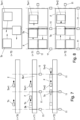
- Fig.1 shows an exemplary structure of a transport system 1 in the form of a linear long stator linear motor
- Fig.2 a planar long stator linear motor. Since the invention is generally applicable to long stator linear motors, a distinction will only be made between linear and planar long stator linear motors if it is necessary or useful for understanding.
- the structural design and geometry of the stator 2 and the transport unit 3 are not important for the invention and can in any case be designed as desired.
- well-known guide structures for guiding a transport unit 3 along the stator 2 and/or for holding a transport unit 3 on the stator 2 are not shown in the figures. Such guide structures can also be designed as desired.
- the transport unit 3 is usually guided magnetically.
- stator linear motor with drive coils Am on the stator 2 as magnetic field generating units.
- moving permanent magnets can also be provided on the stator 2 to generate the moving magnetic field, which interacts with a drive magnet arrangement 3 on the transport unit Tn, or other suitable magnetic field generating units can be provided to generate the moving magnetic field.
- a mixture of different magnetic field generating units on the stator 2 is also conceivable in principle.
- a long stator linear motor consists of a stator 2 and a plurality of transport units Tn (with n > 1) that can be moved along the stator 2.
- 2 drive coils Am (with m > 1) are arranged on the stator, either in Direction of movement one behind the other (linear long stator linear motor as in Fig.1 ) or in one plane of motion (planar long stator linear motor as in Fig.2 ), whereby the drive coils Am of a planar long stator linear motor can also be arranged in several levels lying one above the other.
- the drive coils Am are shown in the figures. However, it is known that the drive coils Am are arranged along the entire range of motion of the long stator linear motor.
- a drive magnet arrangement 3 usually an arrangement of permanent magnets, is arranged on a transport unit Tn. This is also only indicated in the figures for reasons of clarity.
- the drive magnet arrangement 3 and the drive coils Am are known to be arranged in such a way that an air gap of the motor is formed between them.
- the stator 2 can be composed of individual stator segments Sk (with k > 1), with a number of magnetic field generating units (drive coils Am, moving permanent magnets) arranged on each stator segment Sk.
- the stator 2 can also be composed of individual stator sections SAj (with j ⁇ 1) (as in Fig.1 ), which can be connected to each other via switches W, and form the stator 2.
- a stator section SAj can in turn be composed of several stator segments Sk.
- the drive coils Am can be energized by applying a coil voltage and thus generate an electromagnetic field that interacts with the drive magnet arrangement 3 to generate a force and/or a moment acting on the transport unit Tn.
- This electromagnetic field can also be generated by another magnetic field generating unit, for example by moving permanent magnets.
- This force can be generated in the direction of movement (in the planar case, two directions of movement in the plane are possible) and then serves as a propulsion force for moving the transport unit Tn. Rotation on an axis that is orthogonal to the plane of movement is also possible. However, in this way it is also possible to generate a force in a direction transverse to the propulsion force in addition to the propulsion force.
- Such a transverse force can be used, for example, in a structure according to Fig.1 be used to effect an electromagnetic switch position on a switch W (for example as in EP 3 109 998 A1 In a setup as described in Fig.2
- a transverse force can be used to float the transport unit Tn above the plane of movement and/or for rotation around an axis in the direction of movement. This operating principle of a long stator linear motor is well known, so it does not need to be discussed further here.
- a processing station 13 can also be provided on the stator 2, in which an object transported by a transport unit Tn is processed (which prevents any manipulation of the Likewise, a handling device 14, for example a robot, can be provided on the stator 2, for example in a processing station 13 or in the area of a processing station 13, which enables interaction with an object conveyed by a transport unit Tn, even during the movement of the transport unit Tn.
- a handling device 14 for example a robot
- Power electronics 4 can be provided to generate the coil voltage of a drive coil Am.
- a control unit 5 is provided which controls the drive coils Am or the power electronics 4 accordingly.
- the control unit 5 is usually provided in the form of several distributed segment control units, each of which controls a number of drive coils.
- the segment control units can also be connected to one another and/or to a higher-level system control unit 6, for example via a data bus 7.
- the movement of the transport units Tn can be planned or specified, for example in the form of a speed curve depending on the position on the stator 2. Collision monitoring for the transport units Tn can also be implemented in the system control unit 6.
- a control unit 5 can be provided to convert the specifications of the system control unit 6 for the movement of a transport unit Tn into coil voltages in order to realize the desired movement.
- this division into control unit 5 and system control unit 6 is only an example.
- a transport control unit 10 is provided which controls the drive coils Am in order to realize the desired movements of the transport units Tn. How this transport control unit 10 is designed, for example in the form of a cascaded Control system consisting of several interconnected control units as in Fig.1 , is, however, irrelevant for the invention in question.
- a control unit can be a microprocessor-based hardware on which control software is executed.
- the control unit can also be implemented as computer software that is installed and executed on available computer hardware.
- the control unit can also be implemented as an integrated circuit, such as an application-specific integrated circuit (ASIC) or field programmable gate array (FPGA), on which a microprocessor can also be implemented.
- ASIC application-specific integrated circuit
- FPGA field programmable gate array
- the control unit can also be implemented as an analog circuit, for example as an analog computer. Combinations of these are also possible.
- position sensors Ps (with s > 1) are usually also arranged on the stator 2, whereby again only some of the position sensors Ps are shown in the figures for reasons of clarity.
- the position sensors Ps deliver the detected position signals to the control unit 5.
- sensorless position detection can also be implemented to detect the position of a transport unit Tn.
- a closed control loop for controlling the position of a transport unit Tn can also be implemented.
- a position sensor Ps can detect a magnetic field of the transport unit Tn, for example the magnetic field that emanates from the drive magnet arrangement 3, or one that emanates from the transport unit Tn's own position magnets.
- a position sensor Ps can be designed, for example, as a magnetostrictive sensor, magnetoresistive sensor or as a Hall sensor, although of course there are other types of sensors that are able to detect a magnetic field.
- position sensors Ps that detect another physical quantity are also conceivable, for example optical or inductive sensors.
- a system error can affect a single transport unit Tn.
- Examples of such a system error include a tracking error that is too large (deviation between a setpoint and an actual value, for example for position, speed, coil current, propulsion force, the control of the movement of the transport unit Tn), an encoder error (error in the detection of the position, for example if a position magnet on a transport unit is damaged or lost), an operating error (hindering the movement of a transport unit).
- a system error can also affect a specific area the transport system 1, in particular a part of the stator 2 (for example a stator segment or a section of track).
- Examples of such an area error include an overtemperature at a point on the stator 2, a power supply error for a part of the stator 2, a network error in an area of the stator 2, an error in a processing station 13 or a handling device 14 in which a part of the stator 2 is arranged, a mechanical error on the stator 2, etc.
- a system error only affects a part of the transport system 1.
- a system error that affects the entire transport system 1, for example a global power failure or network failure, would inevitably lead to a shutdown of the entire transport system 1 and is therefore not the subject of the invention or would correspond to the previous error reaction in a transport system 1.
- system errors can be detected, for example, in the transport control unit 10, for example based on the known target values and actual values of a transport unit Tn.
- system errors can also be detected by sensors on the transport system 1, for example based on temperature sensors, voltage sensors, current sensors, light barriers, etc. It can be assumed that system errors and the location of the occurrence of a system error are detected on the transport system 1 and are known in the transport control unit 10.
- a system error does not necessarily mean that a transport unit Tn can no longer be moved.
- a system error will in any case mean that a transport unit Tn can no longer be moved in the way in which it would be moved in normal operation (without a system error).
- Normal operation is a setpoint-controlled movement of the transport unit Tn. This means that the transport control unit 10 generates setpoints for the movement of the transport unit Tn and these setpoints can be implemented by energizing the drive coils Am in the area of the transport unit Tn with sufficiently small (predetermined or known) tracking errors.
- a common example of normal operation is a setpoint-position-controlled movement based on a setpoint for the position at any time during the control of the movement, which is achieved by energizing the drive coils Am in the area of the transport unit Tn at any time during the control of the movement (with permissible tracking error).
- This can be implemented in the form of a closed control, whereby an actual value of the position can be recorded or determined.
- a fault scope F is defined on the stator 2, which includes the faulty part of the transport system 1.
- the fault scope F only includes the part of the stator 2 with the faulty part of the transport system 1 and the drive coils Am in the fault scope F are transferred to a specified fault state.
- the part of the stator 2 outside the Error scope F can continue to be operated in normal operation.
- a transport unit Tn that is located in this error scope F is transferred to an error state and in the process carries out a first defined error reaction movement.
- a transport unit Tn that is moved into the error scope is transferred to an error state and in the process carries out a first defined error reaction movement.
- an error scope F is defined around the transport unit Tn. Due to the movement of the transport unit Tn, the error scope F in this case moves with the transport unit Tn.
- the error range F may depend on the system error, as can be seen from the Fig.3 and 4 is explained. If the system error concerns a fault in the transport unit Tn, the error scope F can be placed around the transport unit Tn.
- the error scope F includes, for example, at least the area of the drive coils Am that interact with the transport unit Tn at the time the system error occurs, possibly also a number of drive coils Am before and after the transport unit Tn.
- the transport unit Tn is shown in dashed lines before the occurrence of the system error with a movement arrow to indicate the movement of the transport unit Tn and the error range F.
- Another system error is shown that affects a part of the stator 2, for example an entire stator segment S.
- the error scope F is placed around this faulty system part.
- Such an error scope F over a part of the stator 2 can also be determined if the actual position of a transport unit Tn can no longer be recorded or can no longer be recorded accurately.
- a transport unit Tn-1 that moves into this error scope F can be transferred to an error state (in Fig.1
- the transport unit Tn-1 is shown in dashed lines with a movement arrow before entering the fault range F).
- a transport unit Tn-2 that is already in the fault range when the system fault occurs can also be transferred to a fault state.
- Other transport units Tn-3 that are outside of a fault range F are not affected by the system fault and can continue to move normally. This means that only the part of the transport system 1 where the system fault occurs is affected by the system fault. The rest of the transport system 1 can continue to operate normally.
- the Fig.4 shows this using the example of a planar long stator linear motor.
- the error reaction movement can also depend on the system error. However, it is intended that a specific error reaction movement is defined for each possible system error, which is then implemented by the transport control unit 10. However, the error reaction movement does not necessarily have to be a movement to bring a transport unit Tn to a standstill.
- all drive coils Am within the fault range F can be de-energized. It would also be possible to short-circuit at least one of the affected drive coils Am within the fault range F in order to cause an induction stop (short circuit) for a transport unit Tn, as for example in EP 3 581 428 A1 described, whereby the transport unit Tn can be stopped more quickly. A transport unit Tn which is in the error range F would thus be forced to perform an error reaction movement. If the drive coils Am were de-energized, the transport unit Tn would roll out without any driving force. In the event of a short circuit, a shorter standstill distance for the transport unit Tn could be achieved.
- the drive coils Am in the error range F can also be energized in a different way in order to cause an error reaction movement of the transport unit Tn in possible interaction with a transport unit Tn in the error range F.
- it could be provided to stop the movement of the permanent magnets in the error range F. This would also cause a transport unit Tn to roll out without any force.
- a target position of the movement of the transport unit Tn can no longer be followed, or can only be followed inadequately or inaccurately, due to the system error, a different actual value-controlled movement than the short circuit mentioned above or the power off or the stopping of the movement of the permanent magnets, in particular a movement until the transport unit Tn comes to a standstill, can be implemented as an error reaction movement. This ignores any tracking errors that occur, but the transport unit Tn can be safely brought into a desired state. Of course, there are also Other or further implemented error reaction movements are possible depending on a system error.
- Fig.5 a movement sequence of two transport units Tn, Tn+1 is shown.
- the error scope F includes the drive coils Am, which work together with the transport unit Tn to move. Since this is an error in the first transport unit Tn, the error scope F is moved along with the faulty transport unit Tn in this case (movement indicated by the movement arrow).
- the second transport unit Tn+1 enters the error scope F.
- the second error reaction movement can, for example, be an emergency stop of the second transport unit Tn+1 to avoid a collision.
- the error reaction movement can also result from the state of the drive coils Am in the error scope F, which can result from the error reaction movement of the transport unit Tn.
- the Fig.6 shows such a situation using the example of a planar long stator linear motor at the two points in time TO and T2.
- a setpoint-controlled or actual-value-controlled movement of the second transport unit Tn+1 may not be implemented as a second error reaction movement because the drive coils Am in the area of the error extent F may not be available for the movement of the second transport unit Tn+1 or may not be able to be controlled. In this case, however, at least a coasting or an induction stop of the second transport unit Tn+1 could be possible.
- a system fault occurs, which in this case affects a part of the stator 2.
- area sensors 11, for example light barriers, mechanical or magnetic switches, mechanical or magnetic sensors, inductive sensors, cameras, etc. can also be provided on the stator 2.
- area sensors 11 can be particularly useful in the case of system errors that affect a system for detecting the position of the transport unit Tn (e.g. encoder errors), since the position of the transport unit Tn can no longer be determined or can only be determined with insufficient accuracy.
- the area sensors 11 can be used to locally limit the error scope F, because the exit or entry of a transport unit Tn into the error scope can be detected via area sensors 11 independently of the position detection system.
- the error scope F can be extended depending on the system error, for example by another part of the stator 2, such as the stator segment following in the direction of movement or the following area up to the next area sensor 11 (as in Fig.7 ). If the system error allows it, for example if only a part of the stator 2 is defective but not the first transport unit Tn, then when the first transport unit Tn leaves the error range F, the error state of the first transport unit Tn can be canceled again. The error range F would not have to be expanded. After that, the first transport unit Tn could continue to move with normal movement.
- the second transport unit Tn+1 were to enter the error scope F due to its movement, it would be transferred to the error state and would execute the specified second error reaction movement (for example as described above).
- the scope of the error F is extended due to the system error (as in Fig.7 below), it can happen that after the extension a third transport unit Tn+2 is in the extended error scope F. In this case the third transport unit Tn+2 would be transferred to an error state and would execute a third specified error reaction movement. If the third transport unit Tn+2 moves out of the error scope F, as described above for the first transport unit Tn, either the error scope F be extended again, the error state of the third transport unit Tn+2 be lifted, or an error scope F be placed around the third transport unit Tn+2.
- the Fig.8 shows the extension of the error range F again using the example of a planar long stator linear motor.
- the area of the error range is separated from the remaining range of motion of the stator 2, as for example in Fig.9 and 10 This separation can be done physically with area barriers 12, or logically, for example in the transport control 10.
- the error scope F is defined between two intended area barriers 12, for example barriers, walls, locks, etc.
- the error scope F is closed off to the outside (to the rest of the stator 2) by the area barriers 12.
- a transport unit Tn in the error scope F goes into the error state as described and carries out the intended error reaction movement.
- the area barriers 12 are activated, which physically separate the error scope F from the rest of the movement range of the stator 2.
- the inventive approach of locally limiting the error scope F also allows the following method for operating a transport system 1.
- the transport system 1 is designed in the form of a long stator linear motor, with a stator 2 on which a plurality of magnetic field generation units (drive coils Am, moving permanent magnets, etc.) are arranged and with a plurality of transport units Tn that are simultaneously moved along the stator 2.
- an error scope F is defined on the stator 2, wherein the error scope F only includes a part of the stator 2 with the faulty part of the transport system 1, and a first transport unit Tn that is in this error scope F is transferred to an error state.
- a first defined error reaction movement is carried out.
- this second transport unit Tn+1 is also transferred to an error state and carries out a second specified error reaction movement. If the first transport unit Tn or another transport unit Tn+3 leaves the specified error scope F, the error scope F is either expanded depending on the system error so that the first transport unit Tn or the other transport unit Tn+3 is in the expanded error scope F or the error state of the first transport unit Tn or the other transport unit Tn+3 is canceled or a further error range F is defined around the exiting transport unit Tn, Tn+3. This further error range F does not have to correspond in size to the other error range, but in any case this further error range F is located at a different location on the stator 2.
- the error scope F is moved along with the movement of the first transport unit Tn which has been transferred to the error state if an error of the first transport unit Tn is detected as a system error.
- the fault scope F can either be extended depending on the system fault so that the third transport unit Tn+2 is in the extended fault scope F or the fault state of the third transport unit Tn+2 is removed or a further fault scope F is specified around the third transport unit Tn+2.
- This further fault scope F does not have to correspond in terms of its extent to the other fault scope; in any case, this further fault scope F is located at a different point on the stator 2.
- area sensors 11 and/or area barriers 12 can also be used as described.
Landscapes
- Engineering & Computer Science (AREA)
- Power Engineering (AREA)
- Physics & Mathematics (AREA)
- Electromagnetism (AREA)
- Transportation (AREA)
- Mechanical Engineering (AREA)
- Chemical & Material Sciences (AREA)
- Combustion & Propulsion (AREA)
- Sustainable Development (AREA)
- Sustainable Energy (AREA)
- Life Sciences & Earth Sciences (AREA)
- Non-Mechanical Conveyors (AREA)
- Control Of Linear Motors (AREA)
- Control Of Conveyors (AREA)
- Control Of Vehicles With Linear Motors And Vehicles That Are Magnetically Levitated (AREA)
Claims (14)
- Procédé de fonctionnement d'une installation de transport (1) sous forme d'un moteur linéaire à stator long comprenant un stator (2) sur lequel sont disposées une pluralité d'unités génératrices de champ magnétique et une pluralité d'unités de transport (Tn) qui sont déplacées simultanément le long du stator (2), dans lequel, en cas de défaut de l'installation sur une partie de l'installation de transport (1), un périmètre de défaut (F) est défini sur le stator (2), dans lequel le périmètre de défaut (F) ne comprend qu'une partie du stator (2) avec la partie défectueuse de l'installation de transport (1), et les unités génératrices de champ magnétique sont amenées à passer dans un état de défaut prédéfini dans le périmètre de défaut (F), caractérisé en ce que, dans le cas où une unité de transport (Tn) sort du périmètre de défaut (F) défini, le périmètre de défaut (F) est élargi en fonction du défaut de l'installation, de sorte que l'unité de transport (Tn) sortie se trouve dans le périmètre de défaut (F) élargi ou que, dans le cas de la sortie d'une unité de transport (Tn, Tn+3) du périmètre de défaut (F) défini, un autre périmètre de défaut (F) est établi autour de l'unité de transport (Tn, Tn+3) sortie.
- Procédé selon la revendication 1, caractérisé en ce qu'une première unité de transport (Tn) qui se trouve dans ledit périmètre de défaut (F) ou qui pénètre dans le périmètre de défaut (F) en raison de son mouvement est amenée à passer dans un état de défaut et effectue de ce fait un premier mouvement de réaction au défaut défini.
- Procédé selon la revendication 1 ou 2, caractérisé en ce qu'au moins une bobine d'entraînement (Am), en tant qu'unité génératrice de champ magnétique, est mise hors tension dans le périmètre de défaut (F) défini, ou en ce qu'au moins une bobine d'entraînement (Am), en tant qu'unité génératrice de champ magnétique, est court-circuitée dans le périmètre de défaut (F) défini, ou en ce qu'un mouvement d'au moins un aimant permanent déplacé, en tant qu'unité génératrice de champ magnétique, est interrompu dans le périmètre de défaut (F) défini.
- Procédé selon l'une des revendications 1 à 3, caractérisé en ce que, dans le cas où une seconde unité de transport (Tn+1) déplacée sur le stator (2) pénètre dans le périmètre de défaut (F) défini, ladite seconde unité de transport (Tn+1) est également amenée à passer dans un état de défaut et effectue de ce fait un second mouvement de réaction au défaut défini.
- Procédé selon la revendication 1, caractérisé en ce que, lors de l'élargissement du périmètre de défaut (F), il est vérifié si une autre unité de transport (Tn+1) se trouve, après l'élargissement, dans le périmètre de défaut (F) élargi, et en ce que l'autre unité de transport (Tn+1) ayant atteint le périmètre de défaut (F) du fait de l'élargissement est amenée à passer dans un état de défaut et effectue de ce fait un autre mouvement de réaction au défaut défini.
- Procédé selon l'une des revendications 1 à 3, caractérisé en ce que, dans le cas où une unité de transport (Tn+3) sort du périmètre de défaut (F) défini, l'état de défaut de l'unité de transport (Tn+3) sortie est annulé.
- Procédé selon la revendication 1, caractérisé en ce que le périmètre de défaut (F) est déplacé en association avec le mouvement de l'unité de transport (Tn).
- Procédé selon l'une des revendications 1 à 3, caractérisé en ce que le périmètre de défaut (F) est isolé du reste du périmètre de mouvement du stator (2) par des barrières de zone (12), de sorte qu'aucune unité de transport (Tn) ne peut pénétrer dans le périmètre de défaut (F) ou en sortir.
- Procédé selon l'une des revendications 1 à 7, caractérisé en ce que le périmètre de défaut (F) est défini entre deux capteurs de zone (11) et en ce qu'une entrée d'une unité de transport (Tn) dans le périmètre de défaut (F) ou une sortie d'une unité de transport (Tn) du périmètre de défaut (F) est détectée par un capteur de zone (11).
- Installation de transport sous forme d'un moteur linéaire à stator long comprenant un stator (2) sur lequel sont disposées une pluralité d'unités génératrices de champ magnétique et une pluralité d'unités de transport (Tn) qui sont déplaçables simultanément le long du stator (2), dans laquelle il est prévu une unité de commande de transport (10) qui définit un périmètre de défaut (F) sur le stator (2) en cas de défaut de l'installation sur une partie de l'installation de transport (1), dans laquelle le périmètre de défaut (F) ne comprend qu'une partie du stator (2) avec la partie défectueuse de l'installation de transport (1), et l'unité de commande de transport (10) fait passer les unités génératrices de champ magnétique se trouvant dans le périmètre de défaut (F) dans un état de défaut prédéfini, caractérisée en ce que, dans le cas où une unité de transport (Tn) sort du périmètre de défaut (F) défini, l'unité de commande de transport (10) élargit le périmètre de défaut (F) en fonction du défaut de l'installation, de sorte que l'unité de transport (Tn) sortie se trouve dans le périmètre de défaut (F) élargi ou que, dans le cas où une unité de transport (Tn, Tn+3) sort du périmètre de défaut (F) défini, l'unité de commande de transport (10) établit un autre périmètre de défaut (F) autour de l'unité de transport (Tn, Tn+3) sortie.
- Installation de transport selon la revendication 10, caractérisée en ce que le stator (2) comprend plusieurs segments de stator (Sk), dans laquelle il est prévu sur chaque segment de stator (Sk) au moins une unité génératrice de champ magnétique et le périmètre de défaut (F) comprend au moins un segment de stator (Sk).
- Installation de transport selon la revendication 10, caractérisée en ce que le stator (2) comprend plusieurs segments de stator (Sk), dans laquelle il est prévu sur chaque segment de stator (Sk) plusieurs unités génératrices de champ magnétique et le périmètre de défaut (F) comprend au moins un segment de stator (Sk).
- Installation de transport selon l'une des revendications 10 à 12, caractérisée en ce qu'il est prévu sur le stator (2) des capteurs de zone (11) et en ce que le périmètre de défaut (F) est défini entre deux capteurs de zone (11), dans laquelle les capteurs de zone (11) délimitant le périmètre de défaut (F) permettent de détecter une entrée d'une unité de transport (Tn) dans le périmètre de défaut (F) ou une sortie d'une unité de transport (Tn) du périmètre de défaut (F).
- Installation de transport selon l'une des revendications 10 à 12, caractérisée en ce qu'il est prévu sur le stator (2) des barrières de zone (12) et en ce que le périmètre de défaut (F) est défini entre deux barrières de zone (12), dans laquelle les barrières de zone (12) délimitant le périmètre de défaut (F) empêchent une entrée d'une unité de transport (Tn) dans le périmètre de défaut (F) ou une sortie d'une unité de transport (Tn) du périmètre de défaut (F).
Applications Claiming Priority (1)
| Application Number | Priority Date | Filing Date | Title |
|---|---|---|---|
| ATA50212/2021A AT524925A1 (de) | 2021-03-25 | 2021-03-25 | Verfahren zum Betreiben einer Transportanlage in Form eines Langstatorlinearmotors |
Publications (2)
| Publication Number | Publication Date |
|---|---|
| EP4064549A1 EP4064549A1 (fr) | 2022-09-28 |
| EP4064549B1 true EP4064549B1 (fr) | 2024-11-13 |
Family
ID=80735444
Family Applications (1)
| Application Number | Title | Priority Date | Filing Date |
|---|---|---|---|
| EP22161524.8A Active EP4064549B1 (fr) | 2021-03-25 | 2022-03-11 | Installation de transport sous forme d'un moteur linéaire à stator long et procédé de fonctionnement de ladite installation de transport |
Country Status (5)
| Country | Link |
|---|---|
| US (1) | US11772912B2 (fr) |
| EP (1) | EP4064549B1 (fr) |
| JP (1) | JP2022151718A (fr) |
| CN (1) | CN115122940A (fr) |
| AT (1) | AT524925A1 (fr) |
Families Citing this family (5)
| Publication number | Priority date | Publication date | Assignee | Title |
|---|---|---|---|---|
| AT523565A1 (de) * | 2020-03-05 | 2021-09-15 | B & R Ind Automation Gmbh | Transporteinrichtung |
| IT202200000257A1 (it) * | 2022-01-11 | 2023-07-11 | Ima Spa | Apparecchiatura per trasportare oggetti. |
| KR20250008880A (ko) | 2022-04-13 | 2025-01-16 | 아프레시아 파마슈티칼즈 엘엘씨 | 전방향 자기 운동 장치를 이용한 적층 제조를 위한 시스템 및 방법 |
| EP4593284A1 (fr) * | 2024-01-29 | 2025-07-30 | ABB Schweiz AG | Procédé de fonctionnement d'une machine dotée d'un moteur linéaire |
| CN118387618B (zh) * | 2024-05-14 | 2025-03-14 | 果栗智造(上海)技术股份有限公司 | 物品传输控制方法、装置、存储介质及物品传输系统 |
Family Cites Families (16)
| Publication number | Priority date | Publication date | Assignee | Title |
|---|---|---|---|---|
| JPH0763201B2 (ja) * | 1984-08-22 | 1995-07-05 | 株式会社日立製作所 | リニアモータの給電装置 |
| WO1992000862A1 (fr) * | 1990-07-05 | 1992-01-23 | Utdc Inc. | Systeme de transit sur voie d'arrivee a moteur lineaire |
| EP4033645A1 (fr) | 2011-10-27 | 2022-07-27 | The University of British Columbia | Dispositifs de déplacement et leurs procédés de fabrication, d'utilisation et de commande |
| US9802507B2 (en) | 2013-09-21 | 2017-10-31 | Magnemotion, Inc. | Linear motor transport for packaging and other uses |
| EP3016136B1 (fr) * | 2014-10-27 | 2021-07-21 | Robert Bosch GmbH | Système de transport avec des éléments de transports magnétiquement dirigés et méthode de transport associée |
| DE102015102236B4 (de) * | 2015-02-17 | 2024-05-29 | Beckhoff Automation Gmbh | Steuerungssystem für einen elektrischen Motor |
| AT517219B1 (de) | 2015-06-23 | 2016-12-15 | Bernecker + Rainer Industrie-Elektronik Ges M B H | Verfahren und Langstatorlinearmotor zur Übergabe einer Transporteinheit an einer Übergabeposition |
| AT518354B1 (de) | 2016-02-02 | 2018-06-15 | B & R Ind Automation Gmbh | Verfahren zum Betreiben einer Fördereinrichtung in Form eines Langstatorlinearmotors |
| KR102714144B1 (ko) * | 2016-10-19 | 2024-10-10 | 에스케이하이닉스 주식회사 | 저항성 메모리 장치 및 이를 포함하는 메모리 시스템 |
| DE102016224951A1 (de) * | 2016-12-14 | 2018-06-14 | Robert Bosch Gmbh | Beförderungsvorrichtung mit einem Stator zur kontrollierten Beförderung eines Transportkörpers relativ zum Stator |
| US10562715B2 (en) * | 2017-09-12 | 2020-02-18 | Magnemotion, Inc. | Method and apparatus to diagnose a linear synchronous motor system |
| DE102018209401A1 (de) | 2018-06-13 | 2019-12-19 | Robert Bosch Gmbh | Beförderungsvorrichtung mit Sicherheitsfunktion |
| EP3581428B1 (fr) | 2018-06-14 | 2021-06-09 | B&R Industrial Automation GmbH | Freinage par court-circuit d'un module laser llm |
| JP6962879B2 (ja) * | 2018-08-06 | 2021-11-05 | 公益財団法人鉄道総合技術研究所 | 地絡位置標定方法及び地絡位置標定システム |
| EP3653428A1 (fr) * | 2018-11-19 | 2020-05-20 | B&R Industrial Automation GmbH | Procédé de surveillance sûre du fonctionnement d'un moteur linéaire à stator long |
| US11027615B2 (en) * | 2018-11-29 | 2021-06-08 | Rockwell Automation Technologies, Inc. | System and method for improving travel across joints in a track for a linear motion system |
-
2021
- 2021-03-25 AT ATA50212/2021A patent/AT524925A1/de unknown
-
2022
- 2022-03-11 EP EP22161524.8A patent/EP4064549B1/fr active Active
- 2022-03-14 JP JP2022038882A patent/JP2022151718A/ja active Pending
- 2022-03-24 US US17/703,407 patent/US11772912B2/en active Active
- 2022-03-25 CN CN202210303903.1A patent/CN115122940A/zh active Pending
Also Published As
| Publication number | Publication date |
|---|---|
| EP4064549A1 (fr) | 2022-09-28 |
| US11772912B2 (en) | 2023-10-03 |
| AT524925A1 (de) | 2022-10-15 |
| US20220306406A1 (en) | 2022-09-29 |
| JP2022151718A (ja) | 2022-10-07 |
| CN115122940A (zh) | 2022-09-30 |
Similar Documents
| Publication | Publication Date | Title |
|---|---|---|
| EP4064549A1 (fr) | Procédé de fonctionnement d'une installation de transport sous la forme d'un moteur linéaire à stator long | |
| EP3379719B1 (fr) | Procédé destinés à transferer une unité de transport à une position de transmission | |
| AT519664B1 (de) | Verfahren zur Regelung der Normalkraft einer Transporteinheit eines Langstatorlinearmotors | |
| EP3385803B1 (fr) | Procédé de fonctionnement d'un moteur linéaire à stator déployé | |
| EP2141019B1 (fr) | Procédé de séparation d'au moins deux ponts d'un système de transport segmenté pour matières d'impression | |
| AT518354B1 (de) | Verfahren zum Betreiben einer Fördereinrichtung in Form eines Langstatorlinearmotors | |
| EP4098473A1 (fr) | Installation de transport et procédé permettant de faire fonctionner une installation de transport ayant une surveillance de collisions | |
| EP3363751A2 (fr) | Procédé de transfert d'une unité de transport d'un convoyeur à moteur linéaire à une position de transfert | |
| EP3457560A1 (fr) | Moteur linéaire à stator long | |
| EP3599127A1 (fr) | Procédé de fonctionnement d'un moteur linéaire à stator long pourvu d'unités de transport et surveillance de collision | |
| EP3599126B1 (fr) | Procédé de fonctionnement d'un moteur linéaire à stator long pourvu d'aiguillage | |
| AT520119A1 (de) | Bearbeitungsstation und Verfahren zum Bearbeiten eines Gegenstandes | |
| EP3831639A1 (fr) | Fonction de sécurité pour un système de transport | |
| EP4541740A1 (fr) | Dispositif de transport sous forme d'un moteur linéaire à stator long | |
| WO2005100077A1 (fr) | Dispositif de commande automatique d'un vehicule guide | |
| DE102019117351A1 (de) | Vorrichtung zum Transportieren | |
| EP4361069A1 (fr) | Procédé de fonctionnement d'un moteur planaire | |
| EP3515850B1 (fr) | Dispositif de transport comprenant un dispositif de sécurité destiné à limiter le ralentissement | |
| EP4469777B1 (fr) | Banc d'essai et méthode de sauvegarde des systèmes d'aide à la conduite des véhicules automobiles automatisés | |
| EP4526745A1 (fr) | Procédé de commande du mouvement d'un axe d'entraînement d'une unité d'entraînement | |
| WO2026003076A1 (fr) | Procédé de fonctionnement d'un système de transport linéaire et système de transport linéaire | |
| EP4191352A1 (fr) | Dispositif et procédé de sécurisation du mouvement d'un bien à transporter |
Legal Events
| Date | Code | Title | Description |
|---|---|---|---|
| PUAI | Public reference made under article 153(3) epc to a published international application that has entered the european phase |
Free format text: ORIGINAL CODE: 0009012 |
|
| STAA | Information on the status of an ep patent application or granted ep patent |
Free format text: STATUS: THE APPLICATION HAS BEEN PUBLISHED |
|
| AK | Designated contracting states |
Kind code of ref document: A1 Designated state(s): AL AT BE BG CH CY CZ DE DK EE ES FI FR GB GR HR HU IE IS IT LI LT LU LV MC MK MT NL NO PL PT RO RS SE SI SK SM TR |
|
| STAA | Information on the status of an ep patent application or granted ep patent |
Free format text: STATUS: REQUEST FOR EXAMINATION WAS MADE |
|
| 17P | Request for examination filed |
Effective date: 20230328 |
|
| RBV | Designated contracting states (corrected) |
Designated state(s): AL AT BE BG CH CY CZ DE DK EE ES FI FR GB GR HR HU IE IS IT LI LT LU LV MC MK MT NL NO PL PT RO RS SE SI SK SM TR |
|
| REG | Reference to a national code |
Ref country code: DE Ref legal event code: R079 Ref document number: 502022002104 Country of ref document: DE Free format text: PREVIOUS MAIN CLASS: H02P0006000000 Ipc: H02P0029024000 |
|
| GRAP | Despatch of communication of intention to grant a patent |
Free format text: ORIGINAL CODE: EPIDOSNIGR1 |
|
| STAA | Information on the status of an ep patent application or granted ep patent |
Free format text: STATUS: GRANT OF PATENT IS INTENDED |
|
| RIC1 | Information provided on ipc code assigned before grant |
Ipc: B60L 3/00 20190101ALI20240701BHEP Ipc: H02P 25/064 20160101ALI20240701BHEP Ipc: B60L 13/03 20060101ALI20240701BHEP Ipc: H02P 6/12 20060101ALI20240701BHEP Ipc: H02P 6/00 20160101ALI20240701BHEP Ipc: H02P 29/024 20160101AFI20240701BHEP |
|
| INTG | Intention to grant announced |
Effective date: 20240718 |
|
| GRAS | Grant fee paid |
Free format text: ORIGINAL CODE: EPIDOSNIGR3 |
|
| GRAA | (expected) grant |
Free format text: ORIGINAL CODE: 0009210 |
|
| STAA | Information on the status of an ep patent application or granted ep patent |
Free format text: STATUS: THE PATENT HAS BEEN GRANTED |
|
| AK | Designated contracting states |
Kind code of ref document: B1 Designated state(s): AL AT BE BG CH CY CZ DE DK EE ES FI FR GB GR HR HU IE IS IT LI LT LU LV MC MK MT NL NO PL PT RO RS SE SI SK SM TR |
|
| REG | Reference to a national code |
Ref country code: GB Ref legal event code: FG4D Free format text: NOT ENGLISH |
|
| REG | Reference to a national code |
Ref country code: CH Ref legal event code: EP |
|
| REG | Reference to a national code |
Ref country code: DE Ref legal event code: R096 Ref document number: 502022002104 Country of ref document: DE |
|
| REG | Reference to a national code |
Ref country code: IE Ref legal event code: FG4D Free format text: LANGUAGE OF EP DOCUMENT: GERMAN |
|
| P01 | Opt-out of the competence of the unified patent court (upc) registered |
Free format text: CASE NUMBER: APP_60592/2024 Effective date: 20241111 |
|
| REG | Reference to a national code |
Ref country code: LT Ref legal event code: MG9D |
|
| RAP2 | Party data changed (patent owner data changed or rights of a patent transferred) |
Owner name: ABB SCHWEIZ AG |
|
| REG | Reference to a national code |
Ref country code: NL Ref legal event code: MP Effective date: 20241113 |
|
| PG25 | Lapsed in a contracting state [announced via postgrant information from national office to epo] |
Ref country code: PT Free format text: LAPSE BECAUSE OF FAILURE TO SUBMIT A TRANSLATION OF THE DESCRIPTION OR TO PAY THE FEE WITHIN THE PRESCRIBED TIME-LIMIT Effective date: 20250313 Ref country code: HR Free format text: LAPSE BECAUSE OF FAILURE TO SUBMIT A TRANSLATION OF THE DESCRIPTION OR TO PAY THE FEE WITHIN THE PRESCRIBED TIME-LIMIT Effective date: 20241113 Ref country code: IS Free format text: LAPSE BECAUSE OF FAILURE TO SUBMIT A TRANSLATION OF THE DESCRIPTION OR TO PAY THE FEE WITHIN THE PRESCRIBED TIME-LIMIT Effective date: 20250313 |
|
| PG25 | Lapsed in a contracting state [announced via postgrant information from national office to epo] |
Ref country code: NL Free format text: LAPSE BECAUSE OF FAILURE TO SUBMIT A TRANSLATION OF THE DESCRIPTION OR TO PAY THE FEE WITHIN THE PRESCRIBED TIME-LIMIT Effective date: 20241113 Ref country code: FI Free format text: LAPSE BECAUSE OF FAILURE TO SUBMIT A TRANSLATION OF THE DESCRIPTION OR TO PAY THE FEE WITHIN THE PRESCRIBED TIME-LIMIT Effective date: 20241113 |
|
| PG25 | Lapsed in a contracting state [announced via postgrant information from national office to epo] |
Ref country code: BG Free format text: LAPSE BECAUSE OF FAILURE TO SUBMIT A TRANSLATION OF THE DESCRIPTION OR TO PAY THE FEE WITHIN THE PRESCRIBED TIME-LIMIT Effective date: 20241113 |
|
| PG25 | Lapsed in a contracting state [announced via postgrant information from national office to epo] |
Ref country code: ES Free format text: LAPSE BECAUSE OF FAILURE TO SUBMIT A TRANSLATION OF THE DESCRIPTION OR TO PAY THE FEE WITHIN THE PRESCRIBED TIME-LIMIT Effective date: 20241113 |
|
| PG25 | Lapsed in a contracting state [announced via postgrant information from national office to epo] |
Ref country code: NO Free format text: LAPSE BECAUSE OF FAILURE TO SUBMIT A TRANSLATION OF THE DESCRIPTION OR TO PAY THE FEE WITHIN THE PRESCRIBED TIME-LIMIT Effective date: 20250213 |
|
| PG25 | Lapsed in a contracting state [announced via postgrant information from national office to epo] |
Ref country code: GR Free format text: LAPSE BECAUSE OF FAILURE TO SUBMIT A TRANSLATION OF THE DESCRIPTION OR TO PAY THE FEE WITHIN THE PRESCRIBED TIME-LIMIT Effective date: 20250214 Ref country code: LV Free format text: LAPSE BECAUSE OF FAILURE TO SUBMIT A TRANSLATION OF THE DESCRIPTION OR TO PAY THE FEE WITHIN THE PRESCRIBED TIME-LIMIT Effective date: 20241113 |
|
| PG25 | Lapsed in a contracting state [announced via postgrant information from national office to epo] |
Ref country code: PL Free format text: LAPSE BECAUSE OF FAILURE TO SUBMIT A TRANSLATION OF THE DESCRIPTION OR TO PAY THE FEE WITHIN THE PRESCRIBED TIME-LIMIT Effective date: 20241113 |
|
| PG25 | Lapsed in a contracting state [announced via postgrant information from national office to epo] |
Ref country code: RS Free format text: LAPSE BECAUSE OF FAILURE TO SUBMIT A TRANSLATION OF THE DESCRIPTION OR TO PAY THE FEE WITHIN THE PRESCRIBED TIME-LIMIT Effective date: 20250213 |
|
| REG | Reference to a national code |
Ref country code: DE Ref legal event code: R081 Ref document number: 502022002104 Country of ref document: DE Owner name: ABB SCHWEIZ AG, CH Free format text: FORMER OWNER: B&R INDUSTRIAL AUTOMATION GMBH, EGGELSBERG, AT |
|
| PG25 | Lapsed in a contracting state [announced via postgrant information from national office to epo] |
Ref country code: SM Free format text: LAPSE BECAUSE OF FAILURE TO SUBMIT A TRANSLATION OF THE DESCRIPTION OR TO PAY THE FEE WITHIN THE PRESCRIBED TIME-LIMIT Effective date: 20241113 |
|
| PG25 | Lapsed in a contracting state [announced via postgrant information from national office to epo] |
Ref country code: DK Free format text: LAPSE BECAUSE OF FAILURE TO SUBMIT A TRANSLATION OF THE DESCRIPTION OR TO PAY THE FEE WITHIN THE PRESCRIBED TIME-LIMIT Effective date: 20241113 |
|
| PG25 | Lapsed in a contracting state [announced via postgrant information from national office to epo] |
Ref country code: EE Free format text: LAPSE BECAUSE OF FAILURE TO SUBMIT A TRANSLATION OF THE DESCRIPTION OR TO PAY THE FEE WITHIN THE PRESCRIBED TIME-LIMIT Effective date: 20241113 |
|
| PG25 | Lapsed in a contracting state [announced via postgrant information from national office to epo] |
Ref country code: RO Free format text: LAPSE BECAUSE OF FAILURE TO SUBMIT A TRANSLATION OF THE DESCRIPTION OR TO PAY THE FEE WITHIN THE PRESCRIBED TIME-LIMIT Effective date: 20241113 |
|
| PG25 | Lapsed in a contracting state [announced via postgrant information from national office to epo] |
Ref country code: SK Free format text: LAPSE BECAUSE OF FAILURE TO SUBMIT A TRANSLATION OF THE DESCRIPTION OR TO PAY THE FEE WITHIN THE PRESCRIBED TIME-LIMIT Effective date: 20241113 |
|
| PG25 | Lapsed in a contracting state [announced via postgrant information from national office to epo] |
Ref country code: CZ Free format text: LAPSE BECAUSE OF FAILURE TO SUBMIT A TRANSLATION OF THE DESCRIPTION OR TO PAY THE FEE WITHIN THE PRESCRIBED TIME-LIMIT Effective date: 20241113 |
|
| REG | Reference to a national code |
Ref country code: DE Ref legal event code: R097 Ref document number: 502022002104 Country of ref document: DE |
|
| PG25 | Lapsed in a contracting state [announced via postgrant information from national office to epo] |
Ref country code: SE Free format text: LAPSE BECAUSE OF FAILURE TO SUBMIT A TRANSLATION OF THE DESCRIPTION OR TO PAY THE FEE WITHIN THE PRESCRIBED TIME-LIMIT Effective date: 20241113 |
|
| PLBE | No opposition filed within time limit |
Free format text: ORIGINAL CODE: 0009261 |
|
| STAA | Information on the status of an ep patent application or granted ep patent |
Free format text: STATUS: NO OPPOSITION FILED WITHIN TIME LIMIT |
|
| PG25 | Lapsed in a contracting state [announced via postgrant information from national office to epo] |
Ref country code: MC Free format text: LAPSE BECAUSE OF FAILURE TO SUBMIT A TRANSLATION OF THE DESCRIPTION OR TO PAY THE FEE WITHIN THE PRESCRIBED TIME-LIMIT Effective date: 20241113 |
|
| 26N | No opposition filed |
Effective date: 20250814 |
|
| REG | Reference to a national code |
Ref country code: CH Ref legal event code: H13 Free format text: ST27 STATUS EVENT CODE: U-0-0-H10-H13 (AS PROVIDED BY THE NATIONAL OFFICE) Effective date: 20251024 |
|
| PG25 | Lapsed in a contracting state [announced via postgrant information from national office to epo] |
Ref country code: LU Free format text: LAPSE BECAUSE OF NON-PAYMENT OF DUE FEES Effective date: 20250311 |
|
| REG | Reference to a national code |
Ref country code: BE Ref legal event code: MM Effective date: 20250331 |
|
| PG25 | Lapsed in a contracting state [announced via postgrant information from national office to epo] |
Ref country code: BE Free format text: LAPSE BECAUSE OF NON-PAYMENT OF DUE FEES Effective date: 20250331 |
|
| PG25 | Lapsed in a contracting state [announced via postgrant information from national office to epo] |
Ref country code: CH Free format text: LAPSE BECAUSE OF NON-PAYMENT OF DUE FEES Effective date: 20250331 |
|
| PG25 | Lapsed in a contracting state [announced via postgrant information from national office to epo] |
Ref country code: IE Free format text: LAPSE BECAUSE OF NON-PAYMENT OF DUE FEES Effective date: 20250311 |
|
| PGFP | Annual fee paid to national office [announced via postgrant information from national office to epo] |
Ref country code: DE Payment date: 20260319 Year of fee payment: 5 |
|
| PGFP | Annual fee paid to national office [announced via postgrant information from national office to epo] |
Ref country code: AT Payment date: 20260301 Year of fee payment: 5 |
|
| PGFP | Annual fee paid to national office [announced via postgrant information from national office to epo] |
Ref country code: IT Payment date: 20260324 Year of fee payment: 5 |
|
| PGFP | Annual fee paid to national office [announced via postgrant information from national office to epo] |
Ref country code: FR Payment date: 20260323 Year of fee payment: 5 |