EP4065036B1 - Desinfektionssystem für wassersystem eines zahnpflegegerätes und verfahren zum desinfizieren des wassersystems eines zahnpflegegerätes - Google Patents
Desinfektionssystem für wassersystem eines zahnpflegegerätes und verfahren zum desinfizieren des wassersystems eines zahnpflegegerätes Download PDFInfo
- Publication number
- EP4065036B1 EP4065036B1 EP20893542.9A EP20893542A EP4065036B1 EP 4065036 B1 EP4065036 B1 EP 4065036B1 EP 20893542 A EP20893542 A EP 20893542A EP 4065036 B1 EP4065036 B1 EP 4065036B1
- Authority
- EP
- European Patent Office
- Prior art keywords
- vessel
- water
- disinfectant
- water system
- dental care
- Prior art date
- Legal status (The legal status is an assumption and is not a legal conclusion. Google has not performed a legal analysis and makes no representation as to the accuracy of the status listed.)
- Active
Links
Images

Classifications
-
- A—HUMAN NECESSITIES
- A61—MEDICAL OR VETERINARY SCIENCE; HYGIENE
- A61C—DENTISTRY; APPARATUS OR METHODS FOR ORAL OR DENTAL HYGIENE
- A61C1/00—Dental machines for boring or cutting ; General features of dental machines or apparatus, e.g. hand-piece design
- A61C1/0061—Air and water supply systems; Valves specially adapted therefor
- A61C1/0084—Supply units, e.g. reservoir arrangements, specially adapted pumps
-
- A—HUMAN NECESSITIES
- A61—MEDICAL OR VETERINARY SCIENCE; HYGIENE
- A61C—DENTISTRY; APPARATUS OR METHODS FOR ORAL OR DENTAL HYGIENE
- A61C1/00—Dental machines for boring or cutting ; General features of dental machines or apparatus, e.g. hand-piece design
- A61C1/0061—Air and water supply systems; Valves specially adapted therefor
- A61C1/0076—Sterilising operating fluids or fluid supply elements such as supply lines, filters
-
- A—HUMAN NECESSITIES
- A61—MEDICAL OR VETERINARY SCIENCE; HYGIENE
- A61C—DENTISTRY; APPARATUS OR METHODS FOR ORAL OR DENTAL HYGIENE
- A61C19/00—Dental auxiliary appliances
- A61C19/002—Cleaning devices specially adapted for dental instruments
Definitions
- This disclosure concerns dental care units.
- this disclosure concerns disinfection systems for dental care units.
- Most conventional dental care units comprise a water system configured to provide water for various purposes during dental treatment. Generally, a tab water is being used when the water quality is such that it can be safely used in dental care units. If not, typically, reservoirs specifically configured for bottled water are used.
- water systems of typical dental care units comprise an upright bottle-shaped container with a bottom part, a tapered neck, and a mouth equipped with sealing and support mechanisms for connecting the container to the rest of the water system.
- Publication EP 0403442 A2 discloses one disinfection system for handpieces of a dental surgery apparatus.
- the weighing device is arranged to measure the weight of the vessel holder, vessel and the liquid inside the vessel.
- the system comprises pivoting means arranged to pivot the vessel holder about it, and the weighing device is arranged on the other side of the vessel than the pivoting means.
- the system comprises a disinfectant valve arranged to control the flow of disinfectant supplied into the vessel.
- the system comprises a water controlling valve arranged to control the flow of water supplied into the vessel.
- the system comprises a control unit for executing the disinfection process.
- control unit is configured to calculate the needed amount of disinfectant for achieving a pre-determined concentration of the disinfectant and the water in the vessel by calculating the needed amount of disinfectant based on the measurement data of the weighing device.
- a dental care unit comprises a disinfection system in accordance with the first aspect.
- a method for disinfecting the water system in accordance with the first aspect comprises steps of filling a vessel with an amount of water; weighing the water in the vessel; supplying an amount, based on the weight of the water, of disinfectant from the disinfectant container into the vessel; and supplying the concentration of the disinfectant and the water into the water system of the dental care unit.
- any drawing of the aforementioned drawings may be not drawn to scale such that any element in said drawing may be drawn with inaccurate proportions with respect to other elements in said drawing in order to emphasize certain structural aspects of the embodiment of said drawing.
- a “dental unit”, or a “dental care unit”, or a “dental treatment unit” may refer to a piece of equipment used in provision of dental care.
- a dental care unit may generally comprise any part(s) or element(s) necessary or beneficial for provision of dental care, e.g., a chair, a light source, one or more dental instruments, an instrument holder, and/or data input/output devices, such as a keyboard, a touchscreen, and/or a viewscreen.
- a dental unit may generally further comprise a water system.
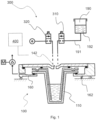
- FIG. 1 shows a partial cross-sectional view of a disinfection system for a water system of a dental care unit. Since FIG. 1 depicts a cross-sectional view of the disinfection system 400, FIG. 1 does not limit shapes of the embodiment of FIG. 1 or any part(s) thereof in any direction forming an angle with the cross-sectional plane of FIG. 1 .
- a “vessel” may refer to a hollow container suitable for holding liquid, such as water.
- a vessel may or may not be (substantially) bowl-shaped and/or cup-shaped.
- the disinfection system 300 of a dental unit may comprise a vessel 110 for receiving and holding liquids, such as water and disinfectant, for the water system of the dental unit, and a vessel holder 160 for holding the vessel inside the dental unit.
- the disinfectant 192 is stored in a disinfectant container 190, from which the disinfectant is supplied into the vessel via a disinfectant supply line 191.
- the disinfectant is supplied into the vessel via fluid duct 142.
- the disinfection system comprises a weighing device 162 for determining weight of any liquids in the vessel.
- the disinfection container 190 may be located inside the dental unit so that the disinfectant 192 is supplied into the vessel via the disinfectant supply line 191 and the fluid duct 142 by the gravity, i.e. the disinfectant container is located above the vessel.
- a disinfectant control valve 310 may be provided within the disinfectant supply line 191 for controlling the supply of the disinfectant.
- the disinfectant control valve 310 may be for example a solenoid valve or any other valve which is suitable to control liquid supply.
- the disinfection container 190 may be filled manually by the user but the supply of the disinfectant may be automated.
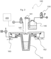
- Fig. 2 shows another embodiment of the disinfection system. Only difference of the system of fig. 2 and the system of fig. 1 is that in the system of fig. 2 disinfectant container 190 is pressurized. The disinfectant is supplied into the vessel via a disinfectant supply line 191 and the fluid duct 142 by adding a pressure inside the disinfectant container 190.
- the system of fig. 2 comprises a pressure control valve 330 for controlling the pressure inside the disinfectant container 190.
- the disinfectant line may be partially directed upwards so that the disinfectant is not flown out of the disinfectant container 190 unintentionally by the gravity. Thus, there is no need for separate disinfectant control valve to control the supply of the disinfectant into the vessel.
- the disinfection system 300 comprises a weighing device 162 for determining weight of any liquids possibly arranged in the vessel 110.
- a weighing device may enable determining, for example, automatically, a quantity of liquid(s) inside a vessel, even in the absence of sensor elements in said vessel. Additionally, or alternatively, such weighing device may facilitate disinfection of a water system by increasing precision of mixing ratios between water and disinfectant.
- the weighing device may be configured to measure the weight of the vessel and the vessel holder, and set a zero-point based on these weights, i.e. calibrate to show only the weight of liquids in the vessel.
- a "weighing device” may refer to any device for measuring a weight of an object.
- a weighing device may generally comprise any part(s) and/or element(s) suitable or necessary for measuring a weight of an object.
- a weighing device may comprise, for example, a balance scale and/or a force-measuring scale.
- the system may comprise a pivoting means 163, such as joint, for pivoting the vessel holder about it.
- the weighing device is arranged on the other side of the vessel than the pivoting means. However, the weighing device may be on the same side of the vessel as the pivoting means 163.
- the control unit 400 may also be configured execute the circulation process of the disinfection liquid in the water system.
- the control unit 400 may be configured to open the water control valve 320, when the weighing device recognizes that the water in the vessel is too low, i.e. the water system is configured to control the amount of water in the system and that the amount is enough for operation. This control may occur even during the operation.
- the control unit 400 may be installed inside the dental unit, or it may be installed outside of the dental unit.
- the control unit 400 may have a central role in the operation of the system. Structurally and functionally it may be based on one or more processors configured to execute machine-readable instructions stored in one or more memories that may comprise at least one of built-in memories or detachable memories.
- FIG. 3 depicts a partial cross-sectional view of a water system 100 for a dental care unit according to an embodiment. Since FIG. 3 depicts a cross-sectional view of the water system 100, FIG. 3 does not limit shapes of the embodiment of FIG. 3 or any part(s) thereof in any direction forming an angle with the cross-sectional plane of FIG. 3 .
- the water system 100 as described for example in FIG.3 , comprises a vessel 110 comprising a bottom 111 and a side wall 114.
- the side wall 114 extends from the bottom 111.
- the side wall 114 has an inner surface 115.
- an "inner surface" of a side wall of a vessel may refer to a surface of said side wall configured to be in contact with a liquid, when the vessel is used for holding said liquid, or a part thereof.
- the vessel 110 may further comprises a flange 116, extending outward from the side wall 114 from an end thereof opposite to the bottom 111. In some embodiments, a vessel may not comprise such flange.
- an “assembled state” may refer to a state of a water system wherein a vessel holder supports a vessel.
- a “disassembled state” may refer to a state of a water system wherein a vessel holder is at a distance from a vessel.
- the water system 100 comprises an insert 120 having a tubular wall structure 121.
- the tubular wall structure 121 as shown for example in FIG. 3 , has open ends 122, 122' and an exterior surface 123.
- tubular is to be interpreted broadly. As such, the term tubular may refer to any elongate and hollow shape, which may have any suitable cross-sectional shape.
- a tubular element may or may not have a circular, substantially circular, elliptical, or polygonal cross section. Additionally, or alternatively, a tubular element may or may not be tapered, cylindrical, and/or curvilinear. Consequently, a “tubular wall structure" may refer to at least part of an insert, having a tubular shape.
- a "first open end" of a tubular wall structure may refer to a bottom end thereof configured for insertion in a vessel. Additionally, or alternatively, the first open end in the tubular wall structure may refer to said tubular wall structure defining an inner volume, accessible via said first open end.
- the tubular wall structure of the insert may also have at its top end a second open end.
- an "exterior surface" of a tubular wall structure may refer to a surface of said tubular wall structure configured to be arranged opposite an inner surface of a vessel in an assembled state of a water system, or a part thereof. Additionally, or alternatively, when a tubular wall structure defines an inner volume, an exterior surface of said tubular wall structure may refer to a surface of said tubular wall structure not connected with said inner volume, or a part thereof.
- the first open end 122 of the tubular wall structure 121 is arranged in the vessel 110 in such manner that a water conduit 130 is formed.
- the water conduit 130 of the embodiment of FIG. 3 extends from the first open end 122 of the tubular wall structure 121 and between the inner surface 115 of the side wall 114 and the exterior surface 123 of the tubular wall structure 121.
- arranging a vessel and an insert in such manner that such water conduit is formed may enable utilization of a significant portion of water in the vessel, even in the absence of tubing extending upstream of the vessel. Additionally or alternatively, such arrangement of a vessel and an insert may facilitate filling, cleaning, and/or disinfection, especially while there is no tubing extending in a water reservoir.
- the exterior surface 123 may be complementarily shaped with the inner surface 115 of the side wall 114 such that the first open end 122 of the tubular wall structure 121 may be arranged in the vessel 110, as depicted in FIG. 3 .
- the exterior surface of the tubular wall structure may be shaped, for example, complementarily, with the inner surface of the side wall of the vessel, enabling arrangement of the first open end of said tubular wall structure in said vessel in an assembled state.
- an exterior surface being "complementarily shaped" with an inner surface may refer to said surfaces being arrangeable so as to form a technically relevant arrangement or element.
- the water conduit 130 may have a thickness t of 1-2 mm, for example. Generally, a higher thickness of a water conduit may facilitate usage of higher mass and/or volumetric flow rates in a water system. In embodiments, a water conduit may have any suitable thickness. In some embodiments, a water conduit may have a thickness of 0,1-1 mm, or at least 1 mm, or at most 2 mm, or at most 5 mm, or at most 10 mm.
- a "thickness" of a water conduit may refer to a transverse dimension of said water conduit.
- a thickness of a water conduit may generally be measured perpendicular to an inner surface of a side wall and/or perpendicular to an exterior surface of a tubular wall structure, i.e. minimum distance between the inner surface of a side wall and exterior surface of the tubular wall structure.
- the tubular wall structure 121 may be removable from the vessel 110 in the disassembled state.
- a tubular wall structure of an insert being removable from a vessel may facilitate cleaning and/or disinfecting said insert and/or said vessel. Additionally, or alternatively, a tubular wall structure of an insert being removable from a vessel may facilitate usage of automated cleaning tools, such as a dishwasher, for purification of said insert and/or said vessel.
- a tubular wall structure of an insert may be removable from a vessel in a disassembled state.
- the vessel 110 has an (imaginary) center line 113, extending through the first open end 122 of the tubular wall structure 121.
- a "center line” may refer to any suitable (imaginary" line.
- a center line may or may not extend through center point(s), such as a center of mass and/or a centroid, of a vessel.
- a center line may or may not extend along a symmetry axis and/or a symmetry plane of a vessel.
- a center line may or may not be arranged (substantially) vertically in an assembled state.
- Such shape of a vessel may generally facilitate insertion of an insert into said vessel and/or removal of an insert from said vessel.
- a vessel may or may not be shaped in such manner.
- the water conduit 130 may form a continuous loop surrounding the exterior surface 123 of the tubular wall structure 121.
- Such cross-sectional shape of a water conduit may facilitate usage of higher mass and/or volumetric flow rates in a water system.
- a water conduit in a cross section of a water system perpendicular to a center line, may or may not form a continuous loop surrounding an exterior surface of a tubular wall structure.
- the top surface 112 may be continuous, as shown for example in FIG. 3 .
- a top surface of a bottom may or may not be continuous.
- a bottom may comprise an extrusion with a through-hole, the extrusion extending through an open end of a tubular wall structure in an assembled state.
- a maximum height difference ⁇ h max between the first open end 122 of the tubular wall structure 121 and the top surface 112 of the bottom 111 may be, for example, 6 millimeters (mm). In embodiments, any suitable maximum height difference may exist between the first open end and a top surface. In some embodiments, a maximum height difference less than or equal to 20 mm, or less than or equal to 10 mm, or less than or equal to 8 mm, or less than or equal to 1 mm may be utilized, for example. A lower maximum height difference may generally enable utilization of a higher portion of water storable in a water system.
- the vessel holder 160 may comprise a through-hole 161, as shown for example in FIG. 3 .
- the vessel 110 is configured to be arranged in the through-hole 161 in the assembled state of the water system 100.
- the flange 116 of the vessel 110 is coupled with the vessel holder 160, and the side wall 114 of the vessel 110 extends through the through-hole 161.
- Such arrangement of a vessel in a through-hole of a vessel holder may generally facilitate forming a fluid-tight coupling between said vessel and said vessel holder.
- a vessel may be configured to be arranged in a through-hole of a vessel holder in an assembled state of the water system.
- said vessel may or may not comprise a flange.
- a side wall of a vessel may be coupled with vessel holder in the absence of any flange in said vessel.
- the insert 120 may be supported by the vessel 110 in the assembled state of the water system 100. Such arrangement may generally facilitate forming a water conduit between an inner surface of a side wall and an exterior surface of a tubular wall structure.
- an insert may or may not be supported by a vessel in an assembled state of a water system.
- an insert may be supported by any suitable means in an assembled state of a water system. For example, in some embodiments, wherein a water system comprises a frame and/or a vessel holder, an insert may be supported by said frame and/or said vessel holder.
- the insert 120 may comprise a projecting part 124, such as flange, extending from the tubular wall structure 121.
- a projecting part 124 such as flange
- an insert may or may not comprise such projecting part.
- the water system 100 may comprise a fluid-tight first seal 171 joining the insert 120 with the lid 140, a fluid-tight second seal 172 joining the lid 140 and the vessel holder 160, and/or a fluid-tight third seal 173 joining the vessel holder 160 with the vessel 110.
- a water system may or may not comprise such first seal, such second seal, and/or such third seal.
- a collection space 170 is defined.
- the water conduit 130 extends from the open end 122 of the tubular wall structure 121 to the collection space 170 between the inner surface 115 of the side wall 114 and the exterior surface 123 of the tubular wall structure 121 to the collection space 170.
- the water conduit 130 may transport water towards the collection space 170 from the vessel 110, when the water system 100 is used.
- Such collection space may generally simplify a structure of a water system. Additionally, or alternatively, such collection space may facilitate usage of more rigid parts and/or elements in a water system, which may, in turn, facilitate mechanical and/or automated cleaning of said water system. In other embodiments, a water system may not comprise such collection space.
- the water system 100 may further comprise a pump 180, which may be arranged upstream of the collection space 170.
- the pump 180 may be used to effect fluid flow, e.g., water flow, in the water conduit 130.
- Such arrangement of a pump may, for example, increase fluid-tightness of a first seal, a second seal, and/or a third seal.
- a water system may or may not comprise such pump.
- any suitable type of pump for example, a positive displacement pump, may be used.
- the water system 100 may further comprise a water delivery line 181.
- the water delivery line 181 provides a fluid communication path after the collection space 170 and/or the pump 180.
- the water delivery line may comprise a water control valve 320 arranged to control the amount of water supplied into the vessel.
- a “water delivery line” may refer to a fluid flow line configured to distribute water from a water reservoir of a water system within said water system.
- a water delivery line may be configured, for example, to supply water via dental instruments into a patient's mouth and/or via a tap to a cup, when a water system is used.
- a water system may or may not comprise a water delivery line.
- a water delivery line may or may not be in fluid communication with a collection space.
- the water system 100 may further comprise a water supply line 150.
- a water system may or may not comprise a water supply line.
- a water system may be supplied with water manually.
- the water supply line 150 may be configured to supply water, e.g., tap water from a public tap water network, into the vessel 110 via the fluid duct 142 of the lid 140, whenever required.
- Such fluid duct may generally facilitate provision of water into a vessel, when a water system is used.
- a water system may or may not comprise a water supply line configured in such manner.
- the water supply line 150 may have a supply line end 151.
- the supply line end 151 In the assembled state of the water system 100, the supply line end 151 is arranged above the fluid duct 142 of the lid 140.
- a minimum height difference ⁇ h min between the top surface 141 of the lid 140 and the supply line end 151 may be, for example, 5 mm, 15 mm, 20 mm, 30 mm, or 50 mm.
- a higher minimum height difference between a top surface and a supply line end may facilitate preventing backflow of water from a vessel into a water supply line, when a water system is used. Protection against pollution of potable water and backflow prevention are discussed, for example, in standard BS EN 1717.
- any suitable minimum height differences may be used.
- a minimum height difference between a top surface and a supply line end in an assembled state of a water system may be at least 10 mm, or at least 20 mm.
- Example embodiments may be implemented in software, hardware, application logic or a combination of software, hardware and application logic.
- the example embodiments can store information relating to various methods described herein. This information can be stored in one or more memories, such as a hard disk, optical disk, magneto-optical disk, RAM, and the like.
- One or more databases can store the information used to implement the example embodiments.
- the databases can be organized using data structures (e.g., records, tables, arrays, fields, graphs, trees, lists, and the like) included in one or more memories or storage devices listed herein.
- the methods described with respect to the example embodiments can include appropriate data structures for storing data collected and/or generated by the methods of the devices and subsystems of the example embodiments in one or more databases.
- the components of the example embodiments may include computer readable medium or memories for holding instructions programmed according to the teachings and for holding data structures, tables, records, and/or other data described herein.
- the application logic, software or an instruction set is maintained on any one of various conventional computer-readable media.
- a "computer-readable medium" may be any media or means that can contain, store, communicate, propagate or transport the instructions for use by or in connection with an instruction execution system, apparatus, or device, such as a computer.
- a computer-readable medium may include a computer-readable storage medium that may be any media or means that can contain or store the instructions for use by or in connection with an instruction execution system, apparatus, or device, such as a computer.
- a computer readable medium can include any suitable medium that participates in providing instructions to a processor for execution. Such a medium can take many forms, including but not limited to, non-volatile media, volatile media, transmission media, and the like.
Landscapes
- Health & Medical Sciences (AREA)
- Oral & Maxillofacial Surgery (AREA)
- Dentistry (AREA)
- Epidemiology (AREA)
- Life Sciences & Earth Sciences (AREA)
- Animal Behavior & Ethology (AREA)
- General Health & Medical Sciences (AREA)
- Public Health (AREA)
- Veterinary Medicine (AREA)
- Engineering & Computer Science (AREA)
- Water Supply & Treatment (AREA)
- Dental Tools And Instruments Or Auxiliary Dental Instruments (AREA)
Claims (10)
- Desinfektionssystem für ein Wassersystem einer Zahnpflegeeinheit, wobei das Desinfektionssystem (300) Folgendes umfasst:- einen Behälter (110) zum Aufnehmen und Lagern von Flüssigkeiten für das Wassersystem der Zahnpflegeeinheit;- einen Behälterhalter (160) zum Halten des Behälters innerhalb der Zahnpflegeeinheit; und- einen Desinfektionsmittelbehälter (190) zur Speicherung von Desinfektionsmittel und eine Desinfektionsmittelzufuhrleitung (191) zum Zuführen von Desinfektionsmittel aus dem Desinfektionsmittelbehälter (190) in den Behälter (110) über eine Fluidleitung (142);dadurch gekennzeichnet, dass das System eine Wiegevorrichtung (162) zum Bestimmen eines Gewichts jeglicher Flüssigkeiten in dem Behälter (110) und eine Steuereinheit (400) umfasst, die konfiguriert ist, um die erforderliche Menge an Desinfektionsmittel zu berechnen, um eine vorbestimmte Konzentration des Desinfektionsmittels und des Wassers in dem Behälter (110) zu erreichen, indem die erforderliche Menge an Desinfektionsmittel basierend auf Messdaten der Wiegevorrichtung (162) berechnet wird.
- Desinfektionssystem nach Anspruch 1, wobei die Wiegevorrichtung (162) konfiguriert ist, um das Gewicht des Behälterhalters (160), des Behälters (110) und der Flüssigkeit innerhalb des Behälters zu messen.
- Desinfektionssystem nach Anspruch 1 oder 2, wobei die Wiegevorrichtung (162) eine Kraftmesswaage umfasst, die zwischen dem Behälterhalter (162) und der Zahnpflegeeinheit angeordnet ist.
- Desinfektionssystem nach Anspruch 3, wobei das Desinfektionssystem (300) ein Schwenkmittel (163) umfasst, das konfiguriert ist, um den Behälterhalter (160) darum zu schwenken, und die Wiegevorrichtung (162) relativ zu dem Schwenkmittel (163) auf der anderen Seite des Behälters (110) konfiguriert ist.
- Desinfektionssystem nach einem der vorhergehenden Ansprüche, wobei das Desinfektionssystem (300) ein Desinfektionsventil (310) umfasst, das konfiguriert ist, um eine Durchflussmenge von in den Behälter (110) zugeführtem Desinfektionsmittel zu steuern.
- Desinfektionssystem nach einem der vorhergehenden Ansprüche, wobei das Desinfektionssystem (300) ein Wassersteuerventil (320) umfasst, das konfiguriert ist, um eine Durchflussmenge von in den Behälter (110) zugeführtem Wasser zu steuern.
- Zahnpflegeeinheit mit dem Desinfektionssystem (300) für ein Wassersystem (100) nach einem der vorhergehenden Ansprüche.
- Verfahren zum Desinfizieren eines Wassersystems (100) einer Zahnpflegeeinheit durch das Desinfektionssystem (300) nach einem der vorhergehenden Ansprüche, wobei das Verfahren die folgenden Schritte umfasst:- Füllen des Behälters (110) mit einer Wassermenge;- Wiegen des Wassers in dem Behälter (110), um eine vorbestimmte Konzentration des Desinfektionsmittels und des Wassers in dem Behälter zu erreichen;- Zuführen, basierend auf dem Gewicht des Wassers, einer Menge an Desinfektionsmittel aus dem Desinfektionsmittelbehälter (190) in den Behälter (110); und- Zuführen der Konzentration des Desinfektionsmittels und des Wassers in das Wassersystem der Zahnpflegeeinheit.
- Verfahren zum Desinfizieren des Wassersystems (100) nach Anspruch 8, das ferner die folgenden Schritte umfasst:- Entfernen der Konzentration des Desinfektionsmittels und des Wassers aus dem Wassersystem (100) der Zahnpflegeeinheit;- Zuführen von Frischwasser in den Behälter (110); und- Spülen des Wassersystems (100) der Zahnpflegeeinheit mit dem in dem Behälter (110) enthaltenen Wasser.
- Verfahren zum Desinfizieren des Wassersystems (100) nach Anspruch 8 oder 9, wobei die Schritte automatisch durch die Steuereinheit (400) ausgeführt werden.
Applications Claiming Priority (3)
| Application Number | Priority Date | Filing Date | Title |
|---|---|---|---|
| FI20196015A FI130292B (en) | 2019-11-26 | 2019-11-26 | DENTAL TREATMENT DEVICE WATER SYSTEM AND DENTAL TREATMENT DEVICE |
| FI20196017A FI20196017A1 (en) | 2019-11-26 | 2019-11-26 | DENTAL WATER SYSTEM DISINFECTION SYSTEM AND METHOD FOR DISINFECTING DENTAL WATER SYSTEM |
| PCT/FI2020/050801 WO2021105567A1 (en) | 2019-11-26 | 2020-11-26 | Disinfection system for water system of a dental care unit and method for desinfecting water system of dental care unit |
Publications (4)
| Publication Number | Publication Date |
|---|---|
| EP4065036A1 EP4065036A1 (de) | 2022-10-05 |
| EP4065036A4 EP4065036A4 (de) | 2023-12-13 |
| EP4065036B1 true EP4065036B1 (de) | 2025-07-02 |
| EP4065036C0 EP4065036C0 (de) | 2025-07-02 |
Family
ID=76129319
Family Applications (2)
| Application Number | Title | Priority Date | Filing Date |
|---|---|---|---|
| EP20893542.9A Active EP4065036B1 (de) | 2019-11-26 | 2020-11-26 | Desinfektionssystem für wassersystem eines zahnpflegegerätes und verfahren zum desinfizieren des wassersystems eines zahnpflegegerätes |
| EP20828297.0A Active EP4065035B1 (de) | 2019-11-26 | 2020-11-26 | Wassersystem für eine zahnärztliche behandlungseinheit und eine zahnärztliche behandlungseinheit |
Family Applications After (1)
| Application Number | Title | Priority Date | Filing Date |
|---|---|---|---|
| EP20828297.0A Active EP4065035B1 (de) | 2019-11-26 | 2020-11-26 | Wassersystem für eine zahnärztliche behandlungseinheit und eine zahnärztliche behandlungseinheit |
Country Status (3)
| Country | Link |
|---|---|
| EP (2) | EP4065036B1 (de) |
| DK (1) | DK4065035T3 (de) |
| WO (2) | WO2021105567A1 (de) |
Citations (2)
| Publication number | Priority date | Publication date | Assignee | Title |
|---|---|---|---|---|
| US20120282568A1 (en) * | 2011-05-05 | 2012-11-08 | Disel Jimmy D | Self-regulating fluid dispensing cap system and method of use |
| DE102012014857B3 (de) * | 2012-07-26 | 2013-11-07 | Ultradent Dental-Medizinische Geräte GmbH & Co.KG | Fluidversorgungseinheit für Zahnbehandlungsgerät |
Family Cites Families (7)
| Publication number | Priority date | Publication date | Assignee | Title |
|---|---|---|---|---|
| DE1834118U (de) * | 1960-11-26 | 1961-07-06 | Siemens Reiniger Werke Ag | Heiz- und ventileinrichtung bei dentaleinheiten. |
| IT1233632B (it) | 1989-06-14 | 1992-04-07 | Augusto Cattani E C Spa Off | Impianto di disinfezione, in particolare per manipoli di riuniti dentali |
| DE19916153C2 (de) * | 1999-04-11 | 2003-12-24 | Duerr Dental Gmbh Co Kg | Dentale Einrichtung zur Behandlung von Geweben mit mechanischen Schwingungen |
| US7351386B2 (en) * | 2002-04-04 | 2008-04-01 | Steris Inc | Cartridge holder for automated reprocessor |
| DK200701479A (da) * | 2007-10-12 | 2009-04-13 | Heka Dental Aps | Vandforsyningsenhed til sikring mod forurening af drikkevand, samt anvendelse af vandforsyningsenheden |
| KR102123007B1 (ko) * | 2013-03-14 | 2020-06-17 | 백스터 인터내셔널 인코포레이티드 | 재사용 가능한 활성화 유닛을 갖는 복막 투석 교환을 위한 시스템 및 방법 |
| GB2522219A (en) * | 2014-01-16 | 2015-07-22 | Icon Technology Systems Ltd | Fluid filter |
-
2020
- 2020-11-26 EP EP20893542.9A patent/EP4065036B1/de active Active
- 2020-11-26 WO PCT/FI2020/050801 patent/WO2021105567A1/en not_active Ceased
- 2020-11-26 WO PCT/FI2020/050800 patent/WO2021105566A1/en not_active Ceased
- 2020-11-26 EP EP20828297.0A patent/EP4065035B1/de active Active
- 2020-11-26 DK DK20828297.0T patent/DK4065035T3/da active
Patent Citations (2)
| Publication number | Priority date | Publication date | Assignee | Title |
|---|---|---|---|---|
| US20120282568A1 (en) * | 2011-05-05 | 2012-11-08 | Disel Jimmy D | Self-regulating fluid dispensing cap system and method of use |
| DE102012014857B3 (de) * | 2012-07-26 | 2013-11-07 | Ultradent Dental-Medizinische Geräte GmbH & Co.KG | Fluidversorgungseinheit für Zahnbehandlungsgerät |
Also Published As
| Publication number | Publication date |
|---|---|
| EP4065036A4 (de) | 2023-12-13 |
| WO2021105567A1 (en) | 2021-06-03 |
| WO2021105566A1 (en) | 2021-06-03 |
| EP4065035B1 (de) | 2024-05-01 |
| DK4065035T3 (da) | 2024-06-17 |
| EP4065035A1 (de) | 2022-10-05 |
| EP4065036C0 (de) | 2025-07-02 |
| EP4065036A1 (de) | 2022-10-05 |
Similar Documents
| Publication | Publication Date | Title |
|---|---|---|
| AU2002239605B2 (en) | Chemical feeder | |
| RU2537583C2 (ru) | Смесительное устройство для приготовления готовых к употреблению медицинских промывочных растворов, прежде всего концентратов для гемодиализа | |
| CA2172711C (en) | Bottle water disinfection system | |
| JP2021007609A (ja) | 透析用カプラ接続具及び透析用薬液供給装置 | |
| KR101899564B1 (ko) | 차아염소산나트륨 주입시스템 | |
| US20230093940A1 (en) | Bioreactor with addition tube | |
| AU2002239605A1 (en) | Chemical feeder | |
| CN107922906A (zh) | 一次性细胞培养装置及培养袋 | |
| CN101622021A (zh) | 用于填充和/或排空透析设备的装置和方法 | |
| EP4065035B1 (de) | Wassersystem für eine zahnärztliche behandlungseinheit und eine zahnärztliche behandlungseinheit | |
| US1883139A (en) | Liquid mixing apparatus | |
| FI130292B (en) | DENTAL TREATMENT DEVICE WATER SYSTEM AND DENTAL TREATMENT DEVICE | |
| ES2934686T3 (es) | Sistema dispensador de producto líquido que libera gas | |
| ES2183122T5 (es) | Procedimiento e instalacion de acondicionamiento y utilizacion de una crema de levadura estabilizada. | |
| FI20196017A1 (en) | DENTAL WATER SYSTEM DISINFECTION SYSTEM AND METHOD FOR DISINFECTING DENTAL WATER SYSTEM | |
| KR20260008668A (ko) | 교정 모듈 및 측정 시스템 | |
| DK147037B (da) | Apparat til impulsvis afgivelse af meget smaa vaeskemaengder, navnlig h2o2 | |
| KR100335155B1 (ko) | 원수소독법과 원수소독용 차아염소산칼슘 자동투입장치 | |
| CN208081585U (zh) | 一种化学消毒血液透析用集中供液系统 | |
| US2105078A (en) | Proportioning device | |
| CN211394140U (zh) | 一种猪舍水消毒系统 | |
| US528232A (en) | Surgical cabinet and irrigating device | |
| CN214713575U (zh) | 消毒设备及清洗系统 | |
| JP2007057165A (ja) | 貯湯槽 | |
| CN209080534U (zh) | 一种耐腐蚀的消毒桶 |
Legal Events
| Date | Code | Title | Description |
|---|---|---|---|
| STAA | Information on the status of an ep patent application or granted ep patent |
Free format text: STATUS: THE INTERNATIONAL PUBLICATION HAS BEEN MADE |
|
| PUAI | Public reference made under article 153(3) epc to a published international application that has entered the european phase |
Free format text: ORIGINAL CODE: 0009012 |
|
| STAA | Information on the status of an ep patent application or granted ep patent |
Free format text: STATUS: REQUEST FOR EXAMINATION WAS MADE |
|
| 17P | Request for examination filed |
Effective date: 20220616 |
|
| AK | Designated contracting states |
Kind code of ref document: A1 Designated state(s): AL AT BE BG CH CY CZ DE DK EE ES FI FR GB GR HR HU IE IS IT LI LT LU LV MC MK MT NL NO PL PT RO RS SE SI SK SM TR |
|
| DAV | Request for validation of the european patent (deleted) | ||
| DAX | Request for extension of the european patent (deleted) | ||
| A4 | Supplementary search report drawn up and despatched |
Effective date: 20231109 |
|
| RIC1 | Information provided on ipc code assigned before grant |
Ipc: A61C 19/00 20060101ALI20231103BHEP Ipc: A61C 1/00 20060101AFI20231103BHEP |
|
| GRAP | Despatch of communication of intention to grant a patent |
Free format text: ORIGINAL CODE: EPIDOSNIGR1 |
|
| STAA | Information on the status of an ep patent application or granted ep patent |
Free format text: STATUS: GRANT OF PATENT IS INTENDED |
|
| INTG | Intention to grant announced |
Effective date: 20250211 |
|
| GRAS | Grant fee paid |
Free format text: ORIGINAL CODE: EPIDOSNIGR3 |
|
| GRAA | (expected) grant |
Free format text: ORIGINAL CODE: 0009210 |
|
| STAA | Information on the status of an ep patent application or granted ep patent |
Free format text: STATUS: THE PATENT HAS BEEN GRANTED |
|
| AK | Designated contracting states |
Kind code of ref document: B1 Designated state(s): AL AT BE BG CH CY CZ DE DK EE ES FI FR GB GR HR HU IE IS IT LI LT LU LV MC MK MT NL NO PL PT RO RS SE SI SK SM TR |
|
| REG | Reference to a national code |
Ref country code: GB Ref legal event code: FG4D |
|
| REG | Reference to a national code |
Ref country code: CH Ref legal event code: EP |
|
| REG | Reference to a national code |
Ref country code: DE Ref legal event code: R096 Ref document number: 602020054004 Country of ref document: DE |
|
| REG | Reference to a national code |
Ref country code: IE Ref legal event code: FG4D |
|
| U01 | Request for unitary effect filed |
Effective date: 20250730 |
|
| U07 | Unitary effect registered |
Designated state(s): AT BE BG DE DK EE FI FR IT LT LU LV MT NL PT RO SE SI Effective date: 20250805 |
|
| U20 | Renewal fee for the european patent with unitary effect paid |
Year of fee payment: 6 Effective date: 20251022 |
|
| PG25 | Lapsed in a contracting state [announced via postgrant information from national office to epo] |
Ref country code: IS Free format text: LAPSE BECAUSE OF FAILURE TO SUBMIT A TRANSLATION OF THE DESCRIPTION OR TO PAY THE FEE WITHIN THE PRESCRIBED TIME-LIMIT Effective date: 20251102 |
|
| PG25 | Lapsed in a contracting state [announced via postgrant information from national office to epo] |
Ref country code: NO Free format text: LAPSE BECAUSE OF FAILURE TO SUBMIT A TRANSLATION OF THE DESCRIPTION OR TO PAY THE FEE WITHIN THE PRESCRIBED TIME-LIMIT Effective date: 20251002 |
|
| PG25 | Lapsed in a contracting state [announced via postgrant information from national office to epo] |
Ref country code: HR Free format text: LAPSE BECAUSE OF FAILURE TO SUBMIT A TRANSLATION OF THE DESCRIPTION OR TO PAY THE FEE WITHIN THE PRESCRIBED TIME-LIMIT Effective date: 20250702 |
|
| PG25 | Lapsed in a contracting state [announced via postgrant information from national office to epo] |
Ref country code: GR Free format text: LAPSE BECAUSE OF FAILURE TO SUBMIT A TRANSLATION OF THE DESCRIPTION OR TO PAY THE FEE WITHIN THE PRESCRIBED TIME-LIMIT Effective date: 20251003 |
|
| PG25 | Lapsed in a contracting state [announced via postgrant information from national office to epo] |
Ref country code: CZ Free format text: LAPSE BECAUSE OF FAILURE TO SUBMIT A TRANSLATION OF THE DESCRIPTION OR TO PAY THE FEE WITHIN THE PRESCRIBED TIME-LIMIT Effective date: 20250702 |
|
| PG25 | Lapsed in a contracting state [announced via postgrant information from national office to epo] |
Ref country code: PL Free format text: LAPSE BECAUSE OF FAILURE TO SUBMIT A TRANSLATION OF THE DESCRIPTION OR TO PAY THE FEE WITHIN THE PRESCRIBED TIME-LIMIT Effective date: 20250702 |
|
| PG25 | Lapsed in a contracting state [announced via postgrant information from national office to epo] |
Ref country code: RS Free format text: LAPSE BECAUSE OF FAILURE TO SUBMIT A TRANSLATION OF THE DESCRIPTION OR TO PAY THE FEE WITHIN THE PRESCRIBED TIME-LIMIT Effective date: 20251002 |
|
| PG25 | Lapsed in a contracting state [announced via postgrant information from national office to epo] |
Ref country code: ES Free format text: LAPSE BECAUSE OF FAILURE TO SUBMIT A TRANSLATION OF THE DESCRIPTION OR TO PAY THE FEE WITHIN THE PRESCRIBED TIME-LIMIT Effective date: 20250702 |
|
| PG25 | Lapsed in a contracting state [announced via postgrant information from national office to epo] |
Ref country code: SM Free format text: LAPSE BECAUSE OF FAILURE TO SUBMIT A TRANSLATION OF THE DESCRIPTION OR TO PAY THE FEE WITHIN THE PRESCRIBED TIME-LIMIT Effective date: 20250702 |
|
| PG25 | Lapsed in a contracting state [announced via postgrant information from national office to epo] |
Ref country code: SK Free format text: LAPSE BECAUSE OF FAILURE TO SUBMIT A TRANSLATION OF THE DESCRIPTION OR TO PAY THE FEE WITHIN THE PRESCRIBED TIME-LIMIT Effective date: 20250702 |
|
| PLBE | No opposition filed within time limit |
Free format text: ORIGINAL CODE: 0009261 |
|
| STAA | Information on the status of an ep patent application or granted ep patent |
Free format text: STATUS: NO OPPOSITION FILED WITHIN TIME LIMIT |