EP4065287B1 - Vorrichtung und verfahren zur herstellung eines beschichteten metallbandes mit verbessertem aussehen - Google Patents
Vorrichtung und verfahren zur herstellung eines beschichteten metallbandes mit verbessertem aussehen Download PDFInfo
- Publication number
- EP4065287B1 EP4065287B1 EP20808483.0A EP20808483A EP4065287B1 EP 4065287 B1 EP4065287 B1 EP 4065287B1 EP 20808483 A EP20808483 A EP 20808483A EP 4065287 B1 EP4065287 B1 EP 4065287B1
- Authority
- EP
- European Patent Office
- Prior art keywords
- gas
- nozzle unit
- strip
- main
- baffle plate
- Prior art date
- Legal status (The legal status is an assumption and is not a legal conclusion. Google has not performed a legal analysis and makes no representation as to the accuracy of the status listed.)
- Active
Links
Images




Classifications
-
- C—CHEMISTRY; METALLURGY
- C23—COATING METALLIC MATERIAL; COATING MATERIAL WITH METALLIC MATERIAL; CHEMICAL SURFACE TREATMENT; DIFFUSION TREATMENT OF METALLIC MATERIAL; COATING BY VACUUM EVAPORATION, BY SPUTTERING, BY ION IMPLANTATION OR BY CHEMICAL VAPOUR DEPOSITION, IN GENERAL; INHIBITING CORROSION OF METALLIC MATERIAL OR INCRUSTATION IN GENERAL
- C23C—COATING METALLIC MATERIAL; COATING MATERIAL WITH METALLIC MATERIAL; SURFACE TREATMENT OF METALLIC MATERIAL BY DIFFUSION INTO THE SURFACE, BY CHEMICAL CONVERSION OR SUBSTITUTION; COATING BY VACUUM EVAPORATION, BY SPUTTERING, BY ION IMPLANTATION OR BY CHEMICAL VAPOUR DEPOSITION, IN GENERAL
- C23C2/00—Hot-dipping or immersion processes for applying the coating material in the molten state without affecting the shape; Apparatus therefor
- C23C2/14—Removing excess of molten coatings; Controlling or regulating the coating thickness
- C23C2/16—Removing excess of molten coatings; Controlling or regulating the coating thickness using fluids under pressure, e.g. air knives
- C23C2/18—Removing excess of molten coatings from elongated material
- C23C2/20—Strips; Plates
-
- C—CHEMISTRY; METALLURGY
- C23—COATING METALLIC MATERIAL; COATING MATERIAL WITH METALLIC MATERIAL; CHEMICAL SURFACE TREATMENT; DIFFUSION TREATMENT OF METALLIC MATERIAL; COATING BY VACUUM EVAPORATION, BY SPUTTERING, BY ION IMPLANTATION OR BY CHEMICAL VAPOUR DEPOSITION, IN GENERAL; INHIBITING CORROSION OF METALLIC MATERIAL OR INCRUSTATION IN GENERAL
- C23C—COATING METALLIC MATERIAL; COATING MATERIAL WITH METALLIC MATERIAL; SURFACE TREATMENT OF METALLIC MATERIAL BY DIFFUSION INTO THE SURFACE, BY CHEMICAL CONVERSION OR SUBSTITUTION; COATING BY VACUUM EVAPORATION, BY SPUTTERING, BY ION IMPLANTATION OR BY CHEMICAL VAPOUR DEPOSITION, IN GENERAL
- C23C2/00—Hot-dipping or immersion processes for applying the coating material in the molten state without affecting the shape; Apparatus therefor
- C23C2/34—Hot-dipping or immersion processes for applying the coating material in the molten state without affecting the shape; Apparatus therefor characterised by the shape of the material to be treated
- C23C2/36—Elongated material
- C23C2/40—Plates; Strips
-
- C—CHEMISTRY; METALLURGY
- C23—COATING METALLIC MATERIAL; COATING MATERIAL WITH METALLIC MATERIAL; CHEMICAL SURFACE TREATMENT; DIFFUSION TREATMENT OF METALLIC MATERIAL; COATING BY VACUUM EVAPORATION, BY SPUTTERING, BY ION IMPLANTATION OR BY CHEMICAL VAPOUR DEPOSITION, IN GENERAL; INHIBITING CORROSION OF METALLIC MATERIAL OR INCRUSTATION IN GENERAL
- C23C—COATING METALLIC MATERIAL; COATING MATERIAL WITH METALLIC MATERIAL; SURFACE TREATMENT OF METALLIC MATERIAL BY DIFFUSION INTO THE SURFACE, BY CHEMICAL CONVERSION OR SUBSTITUTION; COATING BY VACUUM EVAPORATION, BY SPUTTERING, BY ION IMPLANTATION OR BY CHEMICAL VAPOUR DEPOSITION, IN GENERAL
- C23C2/00—Hot-dipping or immersion processes for applying the coating material in the molten state without affecting the shape; Apparatus therefor
- C23C2/50—Controlling or regulating the coating processes
- C23C2/52—Controlling or regulating the coating processes with means for measuring or sensing
- C23C2/524—Position of the substrate
-
- B—PERFORMING OPERATIONS; TRANSPORTING
- B05—SPRAYING OR ATOMISING IN GENERAL; APPLYING FLUENT MATERIALS TO SURFACES, IN GENERAL
- B05C—APPARATUS FOR APPLYING FLUENT MATERIALS TO SURFACES, IN GENERAL
- B05C11/00—Component parts, details or accessories not specifically provided for in groups B05C1/00 - B05C9/00
- B05C11/02—Apparatus for spreading or distributing liquids or other fluent materials already applied to a surface ; Controlling means therefor; Control of the thickness of a coating by spreading or distributing liquids or other fluent materials already applied to the coated surface
- B05C11/06—Apparatus for spreading or distributing liquids or other fluent materials already applied to a surface ; Controlling means therefor; Control of the thickness of a coating by spreading or distributing liquids or other fluent materials already applied to the coated surface with a blast of gas or vapour
-
- B—PERFORMING OPERATIONS; TRANSPORTING
- B05—SPRAYING OR ATOMISING IN GENERAL; APPLYING FLUENT MATERIALS TO SURFACES, IN GENERAL
- B05C—APPARATUS FOR APPLYING FLUENT MATERIALS TO SURFACES, IN GENERAL
- B05C3/00—Apparatus in which the work is brought into contact with a bulk quantity of liquid or other fluent material
- B05C3/02—Apparatus in which the work is brought into contact with a bulk quantity of liquid or other fluent material the work being immersed in the liquid or other fluent material
- B05C3/12—Apparatus in which the work is brought into contact with a bulk quantity of liquid or other fluent material the work being immersed in the liquid or other fluent material for treating work of indefinite length
- B05C3/125—Apparatus in which the work is brought into contact with a bulk quantity of liquid or other fluent material the work being immersed in the liquid or other fluent material for treating work of indefinite length the work being a web, band, strip or the like
Definitions
- the present invention relates to a device and a corresponding method for improving the surface appearance of a hot-dip coated metal strip having a coating thickness adjusted by gas jet wiping.
- the solution prescribed in the present application applies more particularly to metal strips coated with magnesium in a mixture of zinc and aluminium.
- the coating process consisting in dipping a metal strip in a bath of molten metal is well known and used all over the world, especially in the case of coating a steel strip with zinc, aluminium, tin or alloys of those main metal elements to which others may be added such as magnesium, silicon, chromium, strontium, vanadium as well as impurities like Ti, Fe, Ca, etc.
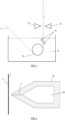
- a strip 1 is firstly dipped in the molten metal bath 2, then deflected by submerged rolls, usually a sink roll 3 and (a) deflecting roll(s) 3(, 4) to finally come out of the bath 2 upward.
- a sink roll 3 usually a sink roll 3 and (a) deflecting roll(s) 3(, 4) to finally come out of the bath 2 upward.
- the most usual method used to perform that operation consists in utilizing the air knife principle. According to this method, a gas is blown at high speed through one or more nozzles 5 often called "air knives" (see FIG. 1 ) onto the running strip conveying the liquid metal.
- the high speed gas nozzle that works like a knife on the liquid film is produced by the gas exhaust from a chamber under pressure 6 through a slot 7 having a length transverse to the running strip and a small thickness ( FIG. 2 ).
- the gas used can be of any type including combustion gas and steam for example but the most usual method consists in using air for cost and availability reasons and nitrogen when a high surface quality is desired.
- Typical values used in the zinc coating method for example are a steel strip running from 20 to 250 meter per minute with a coating thickness comprised between 2 and 40 microns, which requires a gas exiting from a chamber through a single slot opening which thickness is comprised between 0.7 to 2 mm at velocities comprised from 50 m/s to values up to sound velocity (close to 300 m/sec).
- the gas jet is not totally stable after its exit in ambient environment, with the occurrence of high shear stress between the gas jet and the liquid film, and, as a result, waves can be formed in the coating. These are induced by oscillation of the wiping forces on the liquid film.
- a more complex example of confinement box is described in document WO 2014/199194 A1 which discloses an installation for hot dip coating of a metal strip comprising an adjustable confinement box.
- the installation comprises : means for moving said metal strip along a path, a pot for containing a melt bath, and a wiping system comprising at least two nozzles placed on either side of said path downstream the pot, the wiping system having a box with a lower confinement part for confining an atmosphere around the metal strip upstream of said nozzles and an upper confinement part for confining the atmosphere around the metal strip downstream of said nozzles, said wiping system having first moving means for vertically moving the lower confinement part with respect to the pot.
- the nozzles are vertically movable relative to the pot.
- the wiping system also comprises second moving means for vertically moving the upper confinement part with respect to both the pot and the lower confinement part.
- a solution that has also been proposed is a confinement box located downstream just over the nozzle, fed with a non-oxidizing gas by a dedicated system consisting in pipes.
- a dedicated system consisting in pipes.
- Such a system is however quite complex as the box has lateral and top sides and one has to manage the edge baffle system that is used to control the edge over coating.
- it must be located quite close to the strip to be efficient and keep the oxidizer level low compared to ambient environment.
- the atmosphere in the containment area has an oxidising potential less than that of an atmosphere containing 4 vol. °r6 oxygen and 96 vol.% nitrogen and greater than that of an atmosphere containing 0.15 vol. °r6 oxygen and 99.85 vol. °r6 nitrogen.
- the confinement boxes although being very efficient to avoid oxidant potential of the wiping gas on its way toward the strip, create operational problems like creation of skimming that needs to be removed, or dirt due to zinc dust generation and need of slot cleaning as the access to the bath and the nozzle slot are not possible anymore.
- the inventors have identified that, when the line speed is higher than 60 mpm and the coating thickness is below 30 ⁇ m, specific defects occur that are not due to a film oxidation located between the bath surface and the air knife but rather to a film oxidation located after the wiping gas impingement spot because at that location the relative velocity of the wiping gas and the top of the coating is high whereas the coating is close to its finished status.
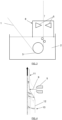
- FIG. 4 shows a typical theoretical film evolution under the gas knife.
- the physics of the process indicates that, in the after-wiping area 11, the coating thickness 12 can still decrease due to the high shear stress induced by the gas flow moving in the same direction than the strip.
- a high relative velocity induces a strong oxidation of the liquid film when the wiping gas is oxidizing the coating metal and thus impacts the final surface quality.
- Document WO 2008/069362 A9 discloses a gas wiping apparatus which includes a body containing a high pressure gas and a multiple nozzle unit disposed at the body to eject the high pressure gas onto a surface of a moving coated steel strip.
- the surface of the coated steel strip passing through a hot dipping bath filled with the molten metal is wiped by a high speed gas jet.
- the gas ejected from the auxiliary nozzles surrounds the gas ejected from the main nozzle, thereby preventing zinc chips from splashing caused by the gas ejected from the main nozzle, even at a high-speed and the steel strip can be adjusted in the coating thickness stably and uniformly.
- Document WO 2005/010229 A1 relates to a method and device for hot-dip coating a metal strip. Once it has left the molten bath, the still molten metal coating which is present on a surface of the metal strip is blown off the metal strip by means of at least one gas flow emanating from a stripping nozzle to achieve a specific coating strength for the final remaining coating on the surface which is respectively impinged upon by the gas flow.
- the gas flow flowing off the respective surface of the metal strip is sucked off by means of a suctioning device which is arranged in the vicinity of the stripping nozzle and the surface of the metal strip.
- the formation of a gas stream flowing parallel to the strip surface is reliably prevented, which on the one hand promotes the oxidation of the coating metal applied to the strip surface and on the other hand would promote the formation of equally undesirable drainage structures.
- the gas stream is instead removed in a controlled manner, and as soon as possible after the gas stream has impacted on the strip surface assigned to it. The occurrence of surface defects and the risk of excessive oxidation of the coating material are thus reduced to a minimum.
- a gas wiping nozzle which includes a primary nozzle portion and at least one secondary nozzle portion provided either or both above and below the primary nozzle portion.
- the secondary nozzle portion jets a gas in a direction tilted from the direction in which the primary nozzle portion jets the gas, and the secondary nozzle portion jets the gas at a lower flow rate than the primary nozzle portion.
- the gas wiping nozzle has a tip whose lower surface forms an angle of 60° or more with the steel strip.
- a jet stripping apparatus comprises a stripping nozzle positioned to direct a stripping gas jet stream against each side of a steel strip emerging from a bath of molten zinc or aluminium/zinc alloy with a layer of bath material thereon, means to supply gas to said stripping nozzle at a pressure sufficient to liberate a relatively strong stripping jet stream therefrom, and surface modifying means spaced closely below said stripping nozzle effective to smooth the surface of said layer prior to it reaching the stripping jet stream.
- Said surface modifying means preferably comprise a smoothing nozzle positioned to direct a relatively weak surface modifying gas jet stream against the layer that is effective to smooth the layer but not to substantially affect the quantity of material passing it.
- the present invention aims to overcome the drawbacks of prior art.
- the invention is intended to improve the appearance of a strip dip-coated with a metal liquid layer whose thickness is adjusted by gas jet wiping, owing to decrease of wiping non-oxidizing gas dilution in air.
- a goal of the invention is also to prevent or minimize the well-known defects of the method such as surface waviness after wiping, cloudy aspect and sag lines, pinhole defects used to appear at high pressure and with thin coatings, etc.
- a first aspect of the present invention relates to a gas wiping device according to claim 1.
- each nozzle unit is expected to generally have a tapered shape with a lower external surface (or external bottom side) and an upper external surface (or external top side) in this respect.
- the term "downstream” means beyond, considering the upward direction of the strip (e.g. downstream/beyond the gas impingement point/spot on the strip).
- the tip of each nozzle unit is the region comprising the gas exit slot.
- the device further comprises at least one of the following characteristics or a suitable combination thereof:
- Another aspect of the invention concerns a gas wiping system comprising several transverse compartments, each compartment having a gas wiping device as described above, said compartments being located in use over the width of the running strip, for modifying the gas wiping jets independently in each compartment.
- Still another aspect of the invention concerns a method for controlling the thickness of a coating layer deposited on a running metal strip in an industrial hot-dip installation, using the gas wiping device according to anyone of the preceding claims, wherein :
- the method further comprises at least one of the following characteristics or a suitable combination thereof:
- the present disclosure thus consists in providing an additional non-oxidizing gas (mass) flow rate lower than 40% of the main flow, expressed in kg per second and per meter of nozzle.
- This flow rate will be preferably between 10 and 20% of the main flow rate to avoid a significant impact on the wiping effect due to the main jet.
- the gas velocity of the additional gas must be low to minimize its interaction on the knife efficiency. Therefore the second slot 7A opening size according to the invention will be higher than the one of the main slot 6A and most preferably between 1.5 and 3 times the main slot opening size.
- the second slot 7A will be 2mm thick with a flow rate from 0.02 to 0.04 kg/seclm.
- the additional non-oxidizing gas In order not to modify the wiping effect of the main gas jet, the additional non-oxidizing gas must be smoothly laid down on the main jet.
- the second slot 7A should not be too close to the exit of the main slot 7, and rather should be typically between 10 and 30mm away and behind the main nozzle 5 exit.
- the second flow must be added to the main flow along the top side 13 of the main nozzle 5 (the strip is supposed to move upwards or the top side of the nozzle is the side thereof located downstream the strip movement). Precise values cannot be given due to a variety of possible designs available according to the invention but the inventors prescribe designs able to get a laminar deposit of the additional flow, such as in the configuration shown in FIG. 5 .
- the general geometry of the nozzle configuration on the after-wiping side is critical in order to keep a type of confinement effect.
- the inventors have observed that if the (w)edge formed by the strip 1 and the second nozzle top side 13A per se is too open, the confinement will be too low.
- experiments have shown that the addition of a small baffle plate 14 to the nozzle top side 13A, which is for example aligned parallel to the strip 1, gives improvement in the confinement 17 ( FIG. 5 ) but while keeping a strip-to-plate distance higher than the nozzle-to-strip distance, preferably about 20mm in all industrial conditions.
- Tests have been run departing from a main nozzle 5 according to prior art as shown on FIG. 2 .
- This nozzle typically has a top side that makes an angle with the strip between 40° and 60°, preferably between 50° to 60°.
- the opening of the nozzle is typically 1mm.
- the additional nozzle 5A has a wider opening 7A, and preferably comprised between 1.5 and 2.5 times the size of the main opening, so comprised between 1.5 and 2.5mm in this case.
- the tip of the additional nozzle 7A is located at a couple of millimetres behind the main nozzle 5 and preferably between 5 and 15mm behind it (i.e. going away from the strip).
- the angle formed by the top side 13A of the second nozzle 5A and the strip is higher than 5° but less than 45°, to assure proper confinement as already mentioned.
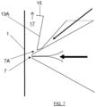
- the top side 13A of the second nozzle 5A is prolonged downstream (or upward in the case of FIG. 5 and 6 ) by a baffle plate 14 which can be parallel in use to the strip 1.
- an additional baffle plate 15 is advantageously added essentially perpendicular to the strip 1 and attached to the 2 nd nozzle 5A (and to its parallel baffle plate 14) to further improve confinement 17 ( FIG. 6 ).
- This plate 15 is located at least at a distance of about 75-100mm over the impingement spot 16 of the main nozzle 5 but certainly lower than 200mm, as after this distance, the shear flow of the liquid film should become very low.
- the second nozzle 5A has a gas supply (i.e. a gas flow rate) comprised between 5% and 30% of the main nozzle 5 gas supply and preferably between 10% and 20% thereof.
- a gas supply i.e. a gas flow rate
- the distance between the first baffle plate 14 and the running strip 1 is adjustable via an actuator 20 (e.g. electric, hydraulic).
- a hinge18 is provided between the first baffle plate 14 and the second nozzle upper surface 13A, and the actuator is able to modify the angle between these two elements, via the hinge 18. So the distance d (resp. d') between the first baffle plate tip (or the second baffle plate tip, in a variant embodiment) and the running strip 1 can be varied by the actuator 20.
- An oxygen sensor 19 is further provided in the confinement region 17, close to the slot 7A of the secondary nozzle unit 5A. This sensor 19 allows to measure the amount of oxygen close to the strip, downstream of the nozzle location.
- This measurement then allows to activate the actuator 20 and modify the geometry of the gas confinement region 17 (for example by reducing distance d), in order to reduce, when needed, the oxygen content in the confinement region 17, or to keep the oxygen content below a predetermined threshold.
- the confinement region is adaptable, depending on the concentration of oxygen measured by the sensor 19.
- the gas wiping device can comprise several transverse compartments, having each a wiping system with the first and second nozzles 5 and 5A, as described above, located over the width of the running strip 1 (not shown).
- a gas wiping device is able to modify the gas wiping jets independently over the width (e. g. central and edge parts respectively) of the running strip 1, according to the requirements. This system is also able to easily adapt to different strip widths.
- Typical data for a tested embodiment in the configuration of FIG. 7 are the following :
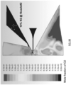
- FIG. 9 represents comparative simulation diagrams of oxygen's distribution, depending on the quantity of gas supply by the second nozzle 5A, in the configuration of FIG. 7 (with two orthogonal baffle plates 14, 15).
- FIG. 9A there is no gas supplied by the second nozzle.
- a gas supply i.e. gas flow rate
- FIG. 9B a gas supply by the second nozzle 5A of 10% of the main nozzle 5 gas supply
- FIG. 9C shows that a gas supply by the second nozzle 5A of 20% or more of main nozzle 5 gas supply.
- jet velocities simulations (not shown), jet velocities are not expected to be much different in the three configurations above, which shows that the method of the invention has little impact on wiping efficiency.
Landscapes
- Chemical & Material Sciences (AREA)
- Chemical Kinetics & Catalysis (AREA)
- Engineering & Computer Science (AREA)
- Materials Engineering (AREA)
- Mechanical Engineering (AREA)
- Metallurgy (AREA)
- Organic Chemistry (AREA)
- Coating With Molten Metal (AREA)
Claims (15)
- Gasabstreifvorrichtung in einer industriellen Schmelztauchanlage zum Steuern der Dicke einer Beschichtung, die auf einem laufenden Metallband abgelegt ist, welches mit Schmelze (1) beschichtet wurde, wobei die Gasabstreifvorrichtung eine Hauptdüseneinheit (5) und eine sekundäre Düseneinheit (5A) umfasst, um einen Abstreifstrahl auf die Oberfläche des laufenden Bandes zu blasen, wobei die Hauptdüseneinheit (5) und die sekundäre Düseneinheit (5A) jeweils mit einer Haupt- und sekundären Kammer (6, 6A) ausgestattet sind, welche durch unter Druck stehendes, nicht oxidierendes Gas versorgt wird, und wobei mindestens ein verlängerter Haupt- und sekundärer Düsenschlitz (7, 7A) in der Spitze der entsprechenden Haupt- und sekundären Düseneinheit (5, 5A) gebildet ist, wobei die Spitzen jeweils eine äußere Oberseite (13, 13A) umfassen, die im Betrieb der nachgelagerten Seite des laufenden Bandes (1) gegenüberliegt und einen Winkel mit der Oberfläche des laufenden Bandes bildet, wobei die sekundäre Düseneinheit (5A), auf der gesamten äußeren Oberseite (13) der Spitze der Hauptdüseneinheit, der Hauptdüseneinheit (5) benachbart ist, so dass die obere äußere Oberfläche (13A) der sekundären Düseneinheit (5A) entworfen ist, um im Betrieb einen Winkel mit der Oberfläche des laufenden Bandes zu bilden, der im Bereich zwischen 5° und 45° liegt, wobei die Dicke der zweiten Schlitzöffnung (7A) im Bereich zwischen 1,5 und 3 Mal der Dicke der ersten Schlitzöffnung (7) liegt, dadurch gekennzeichnet, dass die Spitze der sekundären Düseneinheit (5A) eine äußere Oberseite (13A) aufweist, die nachgelagert durch eine erste Prallplatte (14) verlängert ist, die im Betrieb einen Winkel mit dem laufenden Band (1) bildet, um einen Gaseinschlussbereich (17) zu bilden, und dadurch gekennzeichnet, dass die Gasabstreifvorrichtung auch Folgendes umfasst:- eine Betätigungsvorrichtung (20), die es ermöglicht, einen Abstand (d, d') zwischen einer Spitze der ersten Prallplatte (14) und dem laufenden Band (1) einzustellen, wobei die erste Prallplatte (14) im Verhältnis zur oberen Oberfläche der zweiten Düse (13A) mit Hilfe eines Gelenks (18) schwenkbar montiert ist, so dass die Betätigungsvorrichtung (20) es ermöglicht, einen Winkel zwischen der ersten Prallplatte (14) und der oberen Oberfläche der zweiten Düse (13A) zu modifizieren;- einen Sauerstoffsensor (19), der im Gaseinschlussbereich (17) bereitgestellt ist, nahe der zweiten Schlitzöffnung (7A) der sekundären Düseneinheit (5A), um die Sauerstoffmenge nahe dem laufenden Band (1), nachgelagert von der Düsenposition zu messen, wobei die Messung ermöglicht, die Betätigungsvorrichtung (20) zu aktivieren und weiter die Geometrie des Gaseinschlussbereichs (17) zu modifizieren, insbesondere durch Variieren des Abstands (d, d'), um, wenn erforderlich, den Sauerstoffgehalt im Gaseinschlussbereich (17) zu reduzieren oder den Sauerstoffgehalt darin unter einem vorbestimmten Schwellenwert zu halten.
- Vorrichtung nach Anspruch 1, wobei im Betrieb der Abstandsunterschied zwischen dem Schlitz (7A) der sekundären Düseneinheit (5A) und dem laufenden Band (1) sowie der Abstand zwischen dem Schlitz (7) der Hauptdüseneinheit (5) und dem laufenden Band (1) im Bereich zwischen 5 mm und 30 mm liegt.
- Vorrichtung nach Anspruch 1, wobei die erste Prallplatte (14) an einem Ende, das sich distal von der Spitze der sekundären Düseneinheit befindet, durch eine zweite Prallplatte (15) verlängert ist, die im Betrieb einen zweiten Winkel mit dem laufenden Band (1) bildet, um einen Gaseinschlussbereich (17) mit der Spitze der sekundären Düseneinheit und der ersten Prallplatte (14) zu bilden.
- Vorrichtung nach Anspruch 3, wobei im Betrieb die zweite Prallplatte (15) im Verhältnis zum laufenden Band (1) im Wesentlichen quer/senkrecht oder nachgelagert ausgerichtet ist.
- Vorrichtung nach Anspruch 1, wobei sich die orthogonale Projektion des Schlitzes der sekundären Düseneinheit (5A) auf das laufende Band (1) im Betrieb mindestens 50 mm nachgelagert über einem Aufprallpunkt (16) des Abstreifgases der Hauptdüseneinheit (5) befindet.
- Vorrichtung nach Anspruch 4, wobei sich die orthogonale Projektion der Spitze der zweiten Prallplatte (15) auf das laufende Band (1) im Betrieb 75 bis 100 mm nachgelagert über einem Aufprallpunkt (16) des Abstreifgases der Hauptdüseneinheit (5) befindet.
- Vorrichtung nach Anspruch 4, wobei der Abstand zwischen dem laufenden Band (1) und der zweiten Prallplatte (15) im Bereich zwischen 5 und 30 mm liegt.
- Vorrichtung nach Anspruch 4, wobei der Abstand zwischen dem laufenden Band (1) und der ersten Prallplatte (14) oder der Abstand zwischen dem laufenden Band (1) und der zweiten Prallplatte (15) größer als der Abstand zwischen dem laufenden Band (1) und der Hauptdüseneinheit (5) ist.
- Vorrichtung nach Anspruch 1, wobei die Haupt- und sekundäre Kammer (6, 6A) nicht kommunizierende Kammern sind.
- Gasabstreifsystem, das mehrere querliegende Abteile umfasst, wobei jedes Abteil eine Gasabstreifvorrichtung nach einem der vorhergehenden Ansprüche aufweist, wobei sich die Abteile im Betrieb auf der gesamten Breite des laufenden Bandes (1) befinden, um die Gasabstreifstrahlen in jedem Abteil unabhängig voneinander zu modifizieren.
- Verfahren zum Steuern der Dicke einer Beschichtung, die auf einem laufenden Metallband abgelegt ist, in einer industriellen Schmelztauchanlage unter Verwendung einer Gasabstreifvorrichtung nach einem der Ansprüche 1 bis 9, wobei:- ein erster unter Druck stehender, nicht oxidierender Gasstrahl durch die Hauptdüseneinheit (5) auf das Metallband geblasen wird, welches mit Schmelze (1) aus einem Schmelztauchkessel (2) beschichtet ist;- ein zweiter unter Druck stehender, nicht oxidierender Gasstrahl durch die sekundäre Düseneinheit (5A) auf das Metallband geblasen wird, welches mit Schmelze (1) aus einem Schmelztauchkessel (2) beschichtet ist, wobei sich der Aufprallpunkt des zweiten Gasstrahls unter Berücksichtigung der Laufrichtung des Bandes nahe an oder nachgelagert vom Aufprallpunkt des ersten Gasstrahls befindet;wobei die Gasdurchflussrate aus der sekundären Düseneinheit (5A) gesteuert wird und weniger als 40 % der Gasdurchflussrate aus der Hauptdüseneinheit (5) beträgt.
- Verfahren nach Anspruch 11, wobei die Gasdurchflussrate aus der sekundären Düseneinheit (5A) zwischen 5 und 30 % der Gasdurchflussrate aus der Hauptdüseneinheit (5) beträgt.
- Verfahren nach Anspruch 11, wobei die Gasdurchflussrate aus der sekundären Düseneinheit (5A) im Bereich zwischen 10 und 20 % der Gasdurchflussrate aus der Hauptdüseneinheit (5) beträgt.
- Verfahren nach Anspruch 11, wobei die Gasgeschwindigkeit am Ausgang des zweiten Schlitzes (7A) weniger als 50 Prozent der Gasgeschwindigkeit am Ausgang des Hauptschlitzes (7) beträgt.
- Verfahren nach Anspruch 11, wobei das unter Druck stehende Gas Stickstoff ist.
Applications Claiming Priority (2)
| Application Number | Priority Date | Filing Date | Title |
|---|---|---|---|
| EP19212714.0A EP3827903A1 (de) | 2019-11-29 | 2019-11-29 | Vorrichtung und verfahren zur herstellung eines beschichteten metallbandes mit verbessertem aussehen |
| PCT/EP2020/083390 WO2021105228A1 (en) | 2019-11-29 | 2020-11-25 | Device and method for manufacturing a coated metal strip with improved appearance |
Publications (3)
| Publication Number | Publication Date |
|---|---|
| EP4065287A1 EP4065287A1 (de) | 2022-10-05 |
| EP4065287C0 EP4065287C0 (de) | 2024-11-13 |
| EP4065287B1 true EP4065287B1 (de) | 2024-11-13 |
Family
ID=69063587
Family Applications (2)
| Application Number | Title | Priority Date | Filing Date |
|---|---|---|---|
| EP19212714.0A Withdrawn EP3827903A1 (de) | 2019-11-29 | 2019-11-29 | Vorrichtung und verfahren zur herstellung eines beschichteten metallbandes mit verbessertem aussehen |
| EP20808483.0A Active EP4065287B1 (de) | 2019-11-29 | 2020-11-25 | Vorrichtung und verfahren zur herstellung eines beschichteten metallbandes mit verbessertem aussehen |
Family Applications Before (1)
| Application Number | Title | Priority Date | Filing Date |
|---|---|---|---|
| EP19212714.0A Withdrawn EP3827903A1 (de) | 2019-11-29 | 2019-11-29 | Vorrichtung und verfahren zur herstellung eines beschichteten metallbandes mit verbessertem aussehen |
Country Status (5)
| Country | Link |
|---|---|
| US (1) | US11866829B2 (de) |
| EP (2) | EP3827903A1 (de) |
| CN (1) | CN114502764B (de) |
| CA (1) | CA3162584A1 (de) |
| WO (1) | WO2021105228A1 (de) |
Families Citing this family (6)
| Publication number | Priority date | Publication date | Assignee | Title |
|---|---|---|---|---|
| EP3827903A1 (de) * | 2019-11-29 | 2021-06-02 | Cockerill Maintenance & Ingenierie S.A. | Vorrichtung und verfahren zur herstellung eines beschichteten metallbandes mit verbessertem aussehen |
| WO2023088625A1 (en) | 2021-11-18 | 2023-05-25 | John Cockerill Sa | Method for manufacturing a coated metal strip with improved appearance and wiping device therefor |
| CN115445870B (zh) * | 2022-08-18 | 2024-06-14 | 武汉钢铁有限公司 | 一种消除取向硅钢表面涂层线条的装置和方法 |
| CN115652243B (zh) * | 2022-10-28 | 2025-04-01 | 宝钢湛江钢铁有限公司 | 一种热镀锌镀层厚度调节方法及装置 |
| KR20240154352A (ko) * | 2023-04-18 | 2024-10-25 | 에스케이온 주식회사 | 디스펜싱된 점성유체의 검사와 리페어를 수행하는 장치 및 방법 |
| WO2025088362A1 (en) * | 2023-10-26 | 2025-05-01 | Arcelormittal | Installation for continuously hot dip coating a steel strip and method therefore |
Family Cites Families (25)
| Publication number | Priority date | Publication date | Assignee | Title |
|---|---|---|---|---|
| DE4208578A1 (de) * | 1992-03-13 | 1993-09-16 | Mannesmann Ag | Verfahren zum beschichten der oberflaeche von strangfoermigem gut |
| EP0565272B1 (de) * | 1992-04-06 | 1997-05-21 | BHP STEEL (JLA) PTY Ltd | Abstreifen von flüssigen Beschichtungen |
| FR2690170B1 (fr) * | 1992-04-17 | 1995-03-31 | Clecim Sa | Dispositif à lame d'air de régulation d'un dépôt métallique. |
| DE10333766B4 (de) | 2003-07-23 | 2009-01-22 | Thyssenkrupp Steel Ag | Verfahren und Vorrichtung zum Schmelztauchbeschichten von Metallband |
| WO2005062424A1 (ja) * | 2003-12-18 | 2005-07-07 | Fujitsu Limited | アンテナ装置、電波受信装置、及び、電波送信装置 |
| KR100761307B1 (ko) * | 2005-09-13 | 2007-09-27 | 미쯔비시 히다찌 세이떼쯔 기까이 가부시끼가이샤 | 액체 와이핑 장치 |
| EP2474640B1 (de) * | 2006-05-12 | 2017-02-08 | JFE Steel Corporation | HERSTELLUNGSVERFAHREN FüR EIN HEISSVERZINKTES STAHLBAND |
| KR100843923B1 (ko) | 2006-12-08 | 2008-07-03 | 주식회사 포스코 | 다단 노즐형 가스 와이핑 장치 |
| US9598756B2 (en) * | 2008-10-01 | 2017-03-21 | Nippon Steel & Sumitomo Metal Corporation | Method for producing hot dip plated steel sheet and apparatus for hot dip plating |
| WO2010130884A1 (fr) * | 2009-05-14 | 2010-11-18 | Arcelormittal Investigacion Y Desarrollo Sl | Procédé de fabrication d'une bande métallique revêtue présentant un aspect amélioré |
| WO2010130883A1 (fr) | 2009-05-14 | 2010-11-18 | Arcelormittal Investigacion Y Desarrollo Sl | Procede de fabrication d'une bande metallique revetue presentant un aspect ameliore |
| US20110185969A1 (en) * | 2009-08-21 | 2011-08-04 | Varian Semiconductor Equipment Associates, Inc. | Dual heating for precise wafer temperature control |
| US10138551B2 (en) * | 2010-07-29 | 2018-11-27 | GES Associates LLC | Substrate processing apparatuses and systems |
| JP5915026B2 (ja) * | 2011-08-26 | 2016-05-11 | 住友大阪セメント株式会社 | 温度測定用板状体及びそれを備えた温度測定装置 |
| WO2013080910A1 (ja) * | 2011-11-28 | 2013-06-06 | 株式会社Neomaxマテリアル | めっき膜厚制御用ガスノズルおよびこれを用いた溶融めっき装置 |
| EP2826570B1 (de) * | 2013-07-16 | 2017-02-01 | Cockerill Maintenance & Ingéniérie S.A. | Vorkühlsystem mit interner Pilotsteuerung |
| AU2013392357B2 (en) * | 2013-06-10 | 2017-10-12 | Arcelormittal | Installation for hot dip coating a metal strip comprising an adjustable confinement box |
| KR102075182B1 (ko) * | 2015-12-24 | 2020-02-10 | 주식회사 포스코 | 도금성이 우수한 고강도 용융 아연계 도금 강재 및 그 제조방법 |
| US11786906B2 (en) * | 2016-04-15 | 2023-10-17 | Biofire Defense, Llc | Resistive heaters and anisotropic thermal transfer |
| WO2018150585A1 (ja) * | 2017-02-20 | 2018-08-23 | Primetals Technologies Japan株式会社 | 板反り矯正装置、溶融金属めっき設備、板反り矯正方法 |
| KR102180798B1 (ko) * | 2018-10-19 | 2020-11-19 | 주식회사 포스코 | 용융도금강판의 냉각장치 |
| ES2951125T3 (es) * | 2018-10-24 | 2023-10-18 | John Cockerill S A | Método para controlar la uniformidad del peso de recubrimiento en líneas industriales de galvanización |
| JP7378609B2 (ja) * | 2019-10-16 | 2023-11-13 | ノベリス・インコーポレイテッド | 迅速な焼入れライン |
| EP3827903A1 (de) * | 2019-11-29 | 2021-06-02 | Cockerill Maintenance & Ingenierie S.A. | Vorrichtung und verfahren zur herstellung eines beschichteten metallbandes mit verbessertem aussehen |
| US20220367236A1 (en) * | 2021-05-16 | 2022-11-17 | Applied Materials, Inc. | Heater pedestal with improved uniformity |
-
2019
- 2019-11-29 EP EP19212714.0A patent/EP3827903A1/de not_active Withdrawn
-
2020
- 2020-11-25 EP EP20808483.0A patent/EP4065287B1/de active Active
- 2020-11-25 CA CA3162584A patent/CA3162584A1/en active Pending
- 2020-11-25 CN CN202080070592.8A patent/CN114502764B/zh active Active
- 2020-11-25 WO PCT/EP2020/083390 patent/WO2021105228A1/en not_active Ceased
- 2020-11-25 US US17/775,320 patent/US11866829B2/en active Active
Also Published As
| Publication number | Publication date |
|---|---|
| US20220396861A1 (en) | 2022-12-15 |
| CA3162584A1 (en) | 2021-06-03 |
| CN114502764A (zh) | 2022-05-13 |
| EP4065287A1 (de) | 2022-10-05 |
| EP4065287C0 (de) | 2024-11-13 |
| EP3827903A1 (de) | 2021-06-02 |
| WO2021105228A1 (en) | 2021-06-03 |
| CN114502764B (zh) | 2024-02-13 |
| US11866829B2 (en) | 2024-01-09 |
Similar Documents
| Publication | Publication Date | Title |
|---|---|---|
| US11866829B2 (en) | Device and method for manufacturing a coated metal strip with improved appearance by adjusting a coating thickness using gas jet wiping | |
| CN100393907C (zh) | 液体擦拭装置 | |
| JP5470932B2 (ja) | 溶融金属めっき鋼帯製造設備及び溶融金属めっき鋼帯の製造方法 | |
| TWI717807B (zh) | 熔融金屬鍍覆鋼帶的製造方法及連續熔融金屬鍍覆設備 | |
| JP6372527B2 (ja) | 溶融金属めっき鋼帯の製造方法及び連続溶融金属めっき設備 | |
| WO2023088625A1 (en) | Method for manufacturing a coated metal strip with improved appearance and wiping device therefor | |
| JP5565368B2 (ja) | ワイピング装置およびこれを用いた溶融めっき装置 | |
| JP6500846B2 (ja) | 溶融金属めっき鋼帯の製造方法及び連続溶融金属めっき設備 | |
| JP4857906B2 (ja) | 溶融金属めっき鋼帯の製造方法 | |
| JP5824905B2 (ja) | 溶融金属めっき鋼帯の製造方法 | |
| JP6638872B1 (ja) | 溶融金属めっき鋼帯の製造方法及び連続溶融金属めっき設備 | |
| JP3224208B2 (ja) | 連続溶融金属めっきラインにおける浴面スプラッシュの付着防止方法 | |
| JP4046042B2 (ja) | 連続溶融めっきのワイピング装置 | |
| JP4816105B2 (ja) | 溶融金属めっき鋼帯の製造方法 | |
| JP7839109B2 (ja) | 溶融金属めっき鋼帯の製造方法 | |
| JP5386779B2 (ja) | 溶融めっき鋼板の製造方法及び装置 | |
| JPH11279736A (ja) | 厚目付けに適したガスワイピング方法 | |
| JPH04285146A (ja) | 連続溶融金属めっき装置 | |
| JP5417946B2 (ja) | 溶融金属めっき設備 | |
| JP2018145527A (ja) | 溶融金属めっき鋼帯の製造方法 | |
| JP6635086B2 (ja) | 溶融金属めっき鋼帯の製造方法 | |
| JPH10265930A (ja) | 連続溶融めっきにおける溶融金属付着量の調整方法およびその装置 | |
| JP2002294425A (ja) | ガスワイピング装置 | |
| JPH0651262U (ja) | 連続溶融メッキ装置 | |
| JP2007302959A (ja) | 溶融金属めっき鋼帯の製造方法 |
Legal Events
| Date | Code | Title | Description |
|---|---|---|---|
| STAA | Information on the status of an ep patent application or granted ep patent |
Free format text: STATUS: UNKNOWN |
|
| STAA | Information on the status of an ep patent application or granted ep patent |
Free format text: STATUS: THE INTERNATIONAL PUBLICATION HAS BEEN MADE |
|
| PUAI | Public reference made under article 153(3) epc to a published international application that has entered the european phase |
Free format text: ORIGINAL CODE: 0009012 |
|
| STAA | Information on the status of an ep patent application or granted ep patent |
Free format text: STATUS: REQUEST FOR EXAMINATION WAS MADE |
|
| 17P | Request for examination filed |
Effective date: 20220322 |
|
| AK | Designated contracting states |
Kind code of ref document: A1 Designated state(s): AL AT BE BG CH CY CZ DE DK EE ES FI FR GB GR HR HU IE IS IT LI LT LU LV MC MK MT NL NO PL PT RO RS SE SI SK SM TR |
|
| DAV | Request for validation of the european patent (deleted) | ||
| DAX | Request for extension of the european patent (deleted) | ||
| GRAP | Despatch of communication of intention to grant a patent |
Free format text: ORIGINAL CODE: EPIDOSNIGR1 |
|
| STAA | Information on the status of an ep patent application or granted ep patent |
Free format text: STATUS: GRANT OF PATENT IS INTENDED |
|
| INTG | Intention to grant announced |
Effective date: 20240618 |
|
| GRAS | Grant fee paid |
Free format text: ORIGINAL CODE: EPIDOSNIGR3 |
|
| GRAA | (expected) grant |
Free format text: ORIGINAL CODE: 0009210 |
|
| STAA | Information on the status of an ep patent application or granted ep patent |
Free format text: STATUS: THE PATENT HAS BEEN GRANTED |
|
| AK | Designated contracting states |
Kind code of ref document: B1 Designated state(s): AL AT BE BG CH CY CZ DE DK EE ES FI FR GB GR HR HU IE IS IT LI LT LU LV MC MK MT NL NO PL PT RO RS SE SI SK SM TR |
|
| REG | Reference to a national code |
Ref country code: GB Ref legal event code: FG4D |
|
| REG | Reference to a national code |
Ref country code: CH Ref legal event code: EP |
|
| REG | Reference to a national code |
Ref country code: IE Ref legal event code: FG4D |
|
| REG | Reference to a national code |
Ref country code: DE Ref legal event code: R096 Ref document number: 602020041395 Country of ref document: DE |
|
| U01 | Request for unitary effect filed |
Effective date: 20241203 |
|
| U07 | Unitary effect registered |
Designated state(s): AT BE BG DE DK EE FI FR IT LT LU LV MT NL PT RO SE SI Effective date: 20241212 |
|
| PG25 | Lapsed in a contracting state [announced via postgrant information from national office to epo] |
Ref country code: HR Free format text: LAPSE BECAUSE OF FAILURE TO SUBMIT A TRANSLATION OF THE DESCRIPTION OR TO PAY THE FEE WITHIN THE PRESCRIBED TIME-LIMIT Effective date: 20241113 Ref country code: IS Free format text: LAPSE BECAUSE OF FAILURE TO SUBMIT A TRANSLATION OF THE DESCRIPTION OR TO PAY THE FEE WITHIN THE PRESCRIBED TIME-LIMIT Effective date: 20250313 |
|
| PG25 | Lapsed in a contracting state [announced via postgrant information from national office to epo] |
Ref country code: ES Free format text: LAPSE BECAUSE OF FAILURE TO SUBMIT A TRANSLATION OF THE DESCRIPTION OR TO PAY THE FEE WITHIN THE PRESCRIBED TIME-LIMIT Effective date: 20241113 |
|
| PG25 | Lapsed in a contracting state [announced via postgrant information from national office to epo] |
Ref country code: NO Free format text: LAPSE BECAUSE OF FAILURE TO SUBMIT A TRANSLATION OF THE DESCRIPTION OR TO PAY THE FEE WITHIN THE PRESCRIBED TIME-LIMIT Effective date: 20250213 |
|
| PG25 | Lapsed in a contracting state [announced via postgrant information from national office to epo] |
Ref country code: GR Free format text: LAPSE BECAUSE OF FAILURE TO SUBMIT A TRANSLATION OF THE DESCRIPTION OR TO PAY THE FEE WITHIN THE PRESCRIBED TIME-LIMIT Effective date: 20250214 |
|
| PG25 | Lapsed in a contracting state [announced via postgrant information from national office to epo] |
Ref country code: PL Free format text: LAPSE BECAUSE OF FAILURE TO SUBMIT A TRANSLATION OF THE DESCRIPTION OR TO PAY THE FEE WITHIN THE PRESCRIBED TIME-LIMIT Effective date: 20241113 |
|
| PG25 | Lapsed in a contracting state [announced via postgrant information from national office to epo] |
Ref country code: RS Free format text: LAPSE BECAUSE OF FAILURE TO SUBMIT A TRANSLATION OF THE DESCRIPTION OR TO PAY THE FEE WITHIN THE PRESCRIBED TIME-LIMIT Effective date: 20250213 |
|
| U21 | Renewal fee for the european patent with unitary effect paid with additional fee |
Year of fee payment: 5 Effective date: 20250429 |
|
| REG | Reference to a national code |
Ref country code: CH Ref legal event code: PL |
|
| PG25 | Lapsed in a contracting state [announced via postgrant information from national office to epo] |
Ref country code: SM Free format text: LAPSE BECAUSE OF FAILURE TO SUBMIT A TRANSLATION OF THE DESCRIPTION OR TO PAY THE FEE WITHIN THE PRESCRIBED TIME-LIMIT Effective date: 20241113 |
|
| REG | Reference to a national code |
Ref country code: CH Ref legal event code: PL |
|
| PG25 | Lapsed in a contracting state [announced via postgrant information from national office to epo] |
Ref country code: CH Free format text: LAPSE BECAUSE OF NON-PAYMENT OF DUE FEES Effective date: 20241130 |
|
| PG25 | Lapsed in a contracting state [announced via postgrant information from national office to epo] |
Ref country code: SK Free format text: LAPSE BECAUSE OF FAILURE TO SUBMIT A TRANSLATION OF THE DESCRIPTION OR TO PAY THE FEE WITHIN THE PRESCRIBED TIME-LIMIT Effective date: 20241113 |
|
| PG25 | Lapsed in a contracting state [announced via postgrant information from national office to epo] |
Ref country code: CZ Free format text: LAPSE BECAUSE OF FAILURE TO SUBMIT A TRANSLATION OF THE DESCRIPTION OR TO PAY THE FEE WITHIN THE PRESCRIBED TIME-LIMIT Effective date: 20241113 |
|
| PG25 | Lapsed in a contracting state [announced via postgrant information from national office to epo] |
Ref country code: MC Free format text: LAPSE BECAUSE OF FAILURE TO SUBMIT A TRANSLATION OF THE DESCRIPTION OR TO PAY THE FEE WITHIN THE PRESCRIBED TIME-LIMIT Effective date: 20241113 |
|
| PLBE | No opposition filed within time limit |
Free format text: ORIGINAL CODE: 0009261 |
|
| STAA | Information on the status of an ep patent application or granted ep patent |
Free format text: STATUS: NO OPPOSITION FILED WITHIN TIME LIMIT |
|
| 26N | No opposition filed |
Effective date: 20250814 |
|
| PG25 | Lapsed in a contracting state [announced via postgrant information from national office to epo] |
Ref country code: IE Free format text: LAPSE BECAUSE OF NON-PAYMENT OF DUE FEES Effective date: 20241125 |
|
| GBPC | Gb: european patent ceased through non-payment of renewal fee |
Effective date: 20250213 |
|
| U20 | Renewal fee for the european patent with unitary effect paid |
Year of fee payment: 6 Effective date: 20251117 |
|
| PG25 | Lapsed in a contracting state [announced via postgrant information from national office to epo] |
Ref country code: GB Free format text: LAPSE BECAUSE OF NON-PAYMENT OF DUE FEES Effective date: 20250213 |
|
| PG25 | Lapsed in a contracting state [announced via postgrant information from national office to epo] |
Ref country code: HU Free format text: LAPSE BECAUSE OF FAILURE TO SUBMIT A TRANSLATION OF THE DESCRIPTION OR TO PAY THE FEE WITHIN THE PRESCRIBED TIME-LIMIT; INVALID AB INITIO Effective date: 20201125 |
|
| PG25 | Lapsed in a contracting state [announced via postgrant information from national office to epo] |
Ref country code: CY Free format text: LAPSE BECAUSE OF FAILURE TO SUBMIT A TRANSLATION OF THE DESCRIPTION OR TO PAY THE FEE WITHIN THE PRESCRIBED TIME-LIMIT; INVALID AB INITIO Effective date: 20201125 |