EP4065408B1 - Dispositif de connexion de conducteurs à haute tension - Google Patents
Dispositif de connexion de conducteurs à haute tension Download PDFInfo
- Publication number
- EP4065408B1 EP4065408B1 EP21716337.7A EP21716337A EP4065408B1 EP 4065408 B1 EP4065408 B1 EP 4065408B1 EP 21716337 A EP21716337 A EP 21716337A EP 4065408 B1 EP4065408 B1 EP 4065408B1
- Authority
- EP
- European Patent Office
- Prior art keywords
- voltage
- voltage conductor
- conductors
- housing part
- conductor
- Prior art date
- Legal status (The legal status is an assumption and is not a legal conclusion. Google has not performed a legal analysis and makes no representation as to the accuracy of the status listed.)
- Active
Links
Images


Classifications
-
- H—ELECTRICITY
- H01—ELECTRIC ELEMENTS
- H01R—ELECTRICALLY-CONDUCTIVE CONNECTIONS; STRUCTURAL ASSOCIATIONS OF A PLURALITY OF MUTUALLY-INSULATED ELECTRICAL CONNECTING ELEMENTS; COUPLING DEVICES; CURRENT COLLECTORS
- H01R13/00—Details of coupling devices of the kinds covered by groups H01R12/70 or H01R24/00 - H01R33/00
- H01R13/46—Bases; Cases
- H01R13/53—Bases or cases for heavy duty; Bases or cases for high voltage with means for preventing corona or arcing
-
- B—PERFORMING OPERATIONS; TRANSPORTING
- B60—VEHICLES IN GENERAL
- B60L—PROPULSION OF ELECTRICALLY-PROPELLED VEHICLES; SUPPLYING ELECTRIC POWER FOR AUXILIARY EQUIPMENT OF ELECTRICALLY-PROPELLED VEHICLES; ELECTRODYNAMIC BRAKE SYSTEMS FOR VEHICLES IN GENERAL; MAGNETIC SUSPENSION OR LEVITATION FOR VEHICLES; MONITORING OPERATING VARIABLES OF ELECTRICALLY-PROPELLED VEHICLES; ELECTRIC SAFETY DEVICES FOR ELECTRICALLY-PROPELLED VEHICLES
- B60L53/00—Methods of charging batteries, specially adapted for electric vehicles; Charging stations or on-board charging equipment therefor; Exchange of energy storage elements in electric vehicles
- B60L53/10—Methods of charging batteries, specially adapted for electric vehicles; Charging stations or on-board charging equipment therefor; Exchange of energy storage elements in electric vehicles characterised by the energy transfer between the charging station and the vehicle
- B60L53/14—Conductive energy transfer
- B60L53/16—Connectors, e.g. plugs or sockets, specially adapted for charging electric vehicles
-
- H—ELECTRICITY
- H01—ELECTRIC ELEMENTS
- H01R—ELECTRICALLY-CONDUCTIVE CONNECTIONS; STRUCTURAL ASSOCIATIONS OF A PLURALITY OF MUTUALLY-INSULATED ELECTRICAL CONNECTING ELEMENTS; COUPLING DEVICES; CURRENT COLLECTORS
- H01R13/00—Details of coupling devices of the kinds covered by groups H01R12/70 or H01R24/00 - H01R33/00
- H01R13/02—Contact members
- H01R13/15—Pins, blades or sockets having separate spring member for producing or increasing contact pressure
-
- H—ELECTRICITY
- H01—ELECTRIC ELEMENTS
- H01R—ELECTRICALLY-CONDUCTIVE CONNECTIONS; STRUCTURAL ASSOCIATIONS OF A PLURALITY OF MUTUALLY-INSULATED ELECTRICAL CONNECTING ELEMENTS; COUPLING DEVICES; CURRENT COLLECTORS
- H01R13/00—Details of coupling devices of the kinds covered by groups H01R12/70 or H01R24/00 - H01R33/00
- H01R13/46—Bases; Cases
- H01R13/533—Bases, cases made for use in extreme conditions, e.g. high temperature, radiation, vibration, corrosive environment, pressure
-
- B—PERFORMING OPERATIONS; TRANSPORTING
- B60—VEHICLES IN GENERAL
- B60L—PROPULSION OF ELECTRICALLY-PROPELLED VEHICLES; SUPPLYING ELECTRIC POWER FOR AUXILIARY EQUIPMENT OF ELECTRICALLY-PROPELLED VEHICLES; ELECTRODYNAMIC BRAKE SYSTEMS FOR VEHICLES IN GENERAL; MAGNETIC SUSPENSION OR LEVITATION FOR VEHICLES; MONITORING OPERATING VARIABLES OF ELECTRICALLY-PROPELLED VEHICLES; ELECTRIC SAFETY DEVICES FOR ELECTRICALLY-PROPELLED VEHICLES
- B60L53/00—Methods of charging batteries, specially adapted for electric vehicles; Charging stations or on-board charging equipment therefor; Exchange of energy storage elements in electric vehicles
- B60L53/30—Constructional details of charging stations
- B60L53/302—Cooling of charging equipment
-
- Y—GENERAL TAGGING OF NEW TECHNOLOGICAL DEVELOPMENTS; GENERAL TAGGING OF CROSS-SECTIONAL TECHNOLOGIES SPANNING OVER SEVERAL SECTIONS OF THE IPC; TECHNICAL SUBJECTS COVERED BY FORMER USPC CROSS-REFERENCE ART COLLECTIONS [XRACs] AND DIGESTS
- Y02—TECHNOLOGIES OR APPLICATIONS FOR MITIGATION OR ADAPTATION AGAINST CLIMATE CHANGE
- Y02T—CLIMATE CHANGE MITIGATION TECHNOLOGIES RELATED TO TRANSPORTATION
- Y02T10/00—Road transport of goods or passengers
- Y02T10/60—Other road transportation technologies with climate change mitigation effect
- Y02T10/70—Energy storage systems for electromobility, e.g. batteries
-
- Y—GENERAL TAGGING OF NEW TECHNOLOGICAL DEVELOPMENTS; GENERAL TAGGING OF CROSS-SECTIONAL TECHNOLOGIES SPANNING OVER SEVERAL SECTIONS OF THE IPC; TECHNICAL SUBJECTS COVERED BY FORMER USPC CROSS-REFERENCE ART COLLECTIONS [XRACs] AND DIGESTS
- Y02—TECHNOLOGIES OR APPLICATIONS FOR MITIGATION OR ADAPTATION AGAINST CLIMATE CHANGE
- Y02T—CLIMATE CHANGE MITIGATION TECHNOLOGIES RELATED TO TRANSPORTATION
- Y02T10/00—Road transport of goods or passengers
- Y02T10/60—Other road transportation technologies with climate change mitigation effect
- Y02T10/7072—Electromobility specific charging systems or methods for batteries, ultracapacitors, supercapacitors or double-layer capacitors
-
- Y—GENERAL TAGGING OF NEW TECHNOLOGICAL DEVELOPMENTS; GENERAL TAGGING OF CROSS-SECTIONAL TECHNOLOGIES SPANNING OVER SEVERAL SECTIONS OF THE IPC; TECHNICAL SUBJECTS COVERED BY FORMER USPC CROSS-REFERENCE ART COLLECTIONS [XRACs] AND DIGESTS
- Y02—TECHNOLOGIES OR APPLICATIONS FOR MITIGATION OR ADAPTATION AGAINST CLIMATE CHANGE
- Y02T—CLIMATE CHANGE MITIGATION TECHNOLOGIES RELATED TO TRANSPORTATION
- Y02T90/00—Enabling technologies or technologies with a potential or indirect contribution to GHG emissions mitigation
- Y02T90/10—Technologies relating to charging of electric vehicles
- Y02T90/14—Plug-in electric vehicles
Definitions
- the invention relates to a device for connecting high-voltage conductors comprising at least one first high-voltage conductor, at least one second high-voltage conductor, a device for receiving the first and second high-voltage conductors and at least one connecting device for the current-conducting connection of the at least one first high-voltage conductor to the at least one second high-voltage conductor according to the preamble of patent claim 1.
- a generic device is known from EN 10 2012 201 124 A1
- a cylindrical connecting device has a plurality of longitudinally extending lamellae, each of which is provided on its inside and outside with contacts that are spring-mounted by the lamellae.
- EP0863522 A2 shows an emergency shutdown device for connecting high-voltage conductors comprising at least one first high-voltage conductor, at least one second high-voltage conductor, a device for receiving the first high-voltage conductor and second high-voltage conductor and at least one connecting device for electrically connecting the at least one first high-voltage conductor to the at least one second high-voltage conductor.
- the device also has a compression spring.
- the object of the invention is to provide a device for connecting high-voltage conductors, by means of which at least two high-voltage conductors can be reliably connected and also separated from one another without the use of a tool.
- a preferred field of application of the invention is applications in the automotive sector, in particular applications in electromobility.
- the device according to the invention for connecting high-voltage conductors comprises at least one first high-voltage conductor, at least one second high-voltage conductor, a device for receiving the first and second high-voltage conductors and at least one connecting device for electrically connecting the at least one first high-voltage conductor to the at least one second high-voltage conductor.
- the connecting device has at least one contact bolt pre-tensioned by means of at least one spring for pressing the at least one first high-voltage conductor together with the at least one second high-voltage conductor, wherein the connecting device forms at least one receiving space for at least one of the high-voltage conductors and an abutment for the springs.
- the device for receiving the high-voltage conductors has at least one first receiving space for the first high-voltage conductor and at least one second receiving space for the second high-voltage conductor, which have a common open connection area that allows the first high-voltage conductor and the second high-voltage conductor to be in direct contact with one another.
- the receiving spaces are adapted to the contour of the high-voltage conductors, which are designed, for example, as busbars with a rectangular cross-section and can be easily inserted into the receiving spaces from the outside. The receiving spaces thus ensure that the high-voltage conductors are positively supported in at least two dimensions and also form an abutment against the compressive force exerted by the spring.
- the contact bolt has a pressure piece at one end that is suitable for contact with one of the high-voltage conductors.
- This pressure piece particularly preferably has a spherical segment-shaped or lens-shaped contour on its end face facing the high-voltage conductors. This contour enables the pressure piece to deflect against the pressure of the spring when a high-voltage conductor is inserted and also enables the pressure piece to exert a high point-like contact force on the two high-voltage conductors to be pressed together.
- several connecting devices arranged next to one another or one behind the other can also be provided for connecting two or more high-voltage conductors.
- the pretensioning force of the spring can be adjusted by means of an adjusting device.
- the device can be easily adapted to high-voltage conductors of different thicknesses or to different packages made up of several high-voltage conductors lying one above the other and/or to different currents or electrical powers to be transmitted.
- the receiving spaces for the first and second high-voltage conductors and at least one further receiving space for at least one connecting device are arranged in a common housing part of the device. This enables a particularly compact design and pre-assembly of the connecting devices in this housing part before it is connected to adjacent housing parts.
- An advantageous further development of the invention provides that cooling channels for guiding a particularly liquid cooling medium are provided adjacent to the receiving spaces for the high-voltage conductors.
- a particularly cost-effective manufacture of the device according to the invention is achieved by the fact that the common housing part forming the receiving spaces is designed as an extruded profile.
- extruded profiles can also be manufactured cost-effectively by the meter with complex contours of the receiving spaces and can be adapted to different sized devices required by cutting them to length at any point.
- An advantageous addition to the invention provides that at least two cooling channels are connected by at least one connecting channel, which is in at least a closing part that is tightly adjacent to at least one end face of the extruded profile.
- a closing part with integrated connecting channels ensures a clean end face of a housing part manufactured as an extruded profile and also enables a simple meandering connection and guidance of a cooling medium through the cooling channels.
- a seal is preferably arranged between the end part and the front end of the extruded profile, in which the connecting areas between the cooling channels and the connecting channels are correspondingly recessed.
- the end part can also be permanently glued to the front side of the extruded profile.
- the housing part forming the receiving spaces advantageously has fastening devices for connection to at least one adjacent housing part. These can be designed as threaded holes made perpendicular to the extrusion direction of the housing part or, alternatively, as form-fitting receiving spaces for hexagon or square nuts formed directly in the extrusion process.
- the pressing of a high-voltage conductor into the device according to the invention is facilitated by the fact that the high-voltage conductor facing the contact bolt or the pressure piece has a wedge-shaped bevel at one end which reduces its thickness.
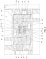
- the Figure 1 shows a device 10 for connecting high-voltage conductors.
- a device 10 for connecting high-voltage conductors.
- Such a device 10 is used, for example, in the field of electromobility.
- the device 10 has a total of three housing parts 12, 14 and 16, of which a first upper housing part 12 establishes the connection from the high-voltage supply lines 25 to the first high-voltage conductor 20.
- a second, middle housing part 14 forms first receiving spaces 143 for the vertical sections 22 of the first high-voltage conductor 20, second receiving spaces 142 for the second high-voltage conductors 30 and further receiving spaces 147 for connecting devices 40.
- the second receiving spaces 142 for the second high-voltage conductor 30 are L-shaped in cross-section. Immediately adjacent to the horizontal leg of the wall of the L-shaped cavity of the second receiving spaces 142, a first receiving space 143 adjoins at the top, into which a vertical section 22 of a first high-voltage conductor 20 opens from above.
- the vertical section 22 penetrates a recess 149 in an upper horizontal cover plate of the second housing part 14.
- the space between the first The partition wall of the housing part 14 located between the first receiving space 143 and the second receiving space 142 has a recess 1425 in the region of the vertical section 22 (see Figure 3 ). Through this recess 1425, the vertical section 22 of the first high-voltage conductor 20 and the second high-voltage conductor 30 come into direct contact with one another and are pressed together there by the pressure of a connecting device 40 described below.
- the housing part 14 Immediately adjacent to this contact area of the first high-voltage conductor 20, 22 and the second high-voltage conductor 30 or to the first receiving spaces 143, the housing part 14 has a further receiving space 147 for the connecting device 40 in a horizontal position.
- the connecting device 40 has a contact bolt 41, which is connected to a cylindrical or cuboid-shaped pressure piece 43 at its end facing the vertical section 22 of the first high-voltage conductor 20.
- the pressure piece 43 penetrates an opening between the receiving spaces 147 and 143, the shape of which is adapted to its cross section. The opening thus also serves to guide the pressure piece 43.
- the pressure piece 43 has a spherical cap-shaped or lens-shaped contour 44 on its front side facing the vertical section 22.
- the pressure piece 43 is acted upon on its other end by a first end of a spring 42 designed as a compression spring, which surrounds the contact bolt 41 and is supported with a second end on an abutment 148 delimiting the further receiving space 147.
- a spring 42 designed as a compression spring, which surrounds the contact bolt 41 and is supported with a second end on an abutment 148 delimiting the further receiving space 147.
- an adjusting device 45 which can be designed as an adjusting nut, for example, the preload of the spring 42 and/or the spring travel by which the pressure piece 43 can deviate against the pressure of the spring 42 can preferably be adjusted.
- the pressure piece 43 with its rounded contour 44 is pressed against the vertical section 22, whereby the first high-voltage conductor 20 comes into a conductive connection with the second high-voltage conductor 30.
- the contact force of the spring 42 is selected so that even high currents of more than 100 A at high voltages of, for example, 400 V, they can be transmitted reliably and largely without loss under all external conditions affecting a vehicle (vibrations, shocks, temperature fluctuations, humidity).
- the lower end of the vertical section 22 is preferably provided with a wedge-shaped bevel 23 on the surface facing the contour 44.
- This bevel 23 enables the vertical section 22 to be pushed into the receiving space 143 from above when the first high-voltage conductor 30 is already mounted, and the pressure piece 43 loaded by the spring 42 with its rounded contour 44 is pushed to the side accordingly.
- cooling channels 144 are provided adjacent to the receiving spaces 142 and 143 for the high-voltage conductors 22 and 30.
- a liquid coolant is pumped through the cooling channels 144, which serves to dissipate the heat that inevitably arises from the connection area of the high-voltage conductors 22 and 30 due to the transmission of high electrical power.
- the highly thermally conductive plastic consists of a polymer material with thermally conductive boron nitride fillers, in particular PA6, PA66, PBT, PPS, PEEK, LPS or TPE.
- thermally conductive boron nitride fillers in particular PA6, PA66, PBT, PPS, PEEK, LPS or TPE.
- Such a material can be obtained, for example, from 3M ® .
- cooling channels 144 can be connected to one another in a meandering manner by U-shaped connecting channels 151, wherein the connecting channels 151 are preferably arranged in a closing part 150, which tightly closes off the middle housing part 14, which is designed as an extruded profile 145, at least on one end face.
- the sealing is achieved either by a seal 155 cut out in the area of the cooling channels 144 or the connecting channels 151 or by a corresponding permanent bond at the same location.
- the upper, first housing part 12 and the middle, second housing part 14 are connected by Figure 1 shown connecting screws 18 and fastening devices 141 provided in the middle housing part 14.
- the fastening devices 141 can be formed by threads machined into the middle housing part 14.
- rectangular receiving channels for the positive reception of hexagon or square nuts with through holes arranged above them are also possible, through which the connecting screws 18 are screwed into the relevant nuts.
- the lower, third housing part 16 is connected by connecting screws 18A to fastening devices 141A on the middle housing part 14.
- several high-voltage conductors other than the two high-voltage conductors 20, 30 shown in the embodiment can also be connected by appropriate connecting devices 40. It is also possible to connect two or more high-voltage conductors 20, 30 lying one above the other by means of several connecting devices 40 arranged next to one another or one behind the other, in which case an even stronger connection of the high-voltage conductors is achieved by means of several contact forces generated by springs 42.
- the conductive connection can be easily established or broken without the use of tools.
Landscapes
- Engineering & Computer Science (AREA)
- Power Engineering (AREA)
- Transportation (AREA)
- Mechanical Engineering (AREA)
- Connector Housings Or Holding Contact Members (AREA)
Claims (12)
- Dispositif (10) pour relier des conducteurs à haute tension (20, 21, 22 ; 30) comprenant au moins un premier conducteur à haute tension (20, 21, 22), au moins un deuxième conducteur à haute tension (30), un dispositif (14) destiné à recevoir le premier conducteur à haute tension (20, 21, 22) et le deuxième conducteur à haute tension (30) et au moins un dispositif de connexion (40) destiné à relier par conduction de courant l'au moins un premier conducteur à haute tension (20, 21, 22) avec l'au moins un deuxième conducteur à haute tension (30), le dispositif de connexion (40) présentant au moins un boulon de contact (41) précontraint au moyen d'au moins un ressort (42) pour comprimer l'au moins un premier conducteur à haute tension (20, 21, 22) avec l'au moins un deuxième conducteur à haute tension (30), dans lequel le dispositif de connexion (40) présente au moins un espace de réception (142, 143) pour au moins l'un des conducteurs à haute tension (20, 21, 22) ; 30) et au moins une butée (148) pour le ressort (42),
dans lequel le boulon de contact (41) présente à une extrémité une pièce de pression (43) appropriée pour l'application sur l'un des conducteurs à haute tension (20, 21, 22 ; 30). - Dispositif (10) selon la revendication 1, caractérisé en ce que le dispositif (14) comporte un premier espace de réception (143) pour le premier conducteur à haute tension (20, 21, 22) et un deuxième espace de réception (142) pour le deuxième conducteur à haute tension (30) avec une zone de liaison ouverte commune qui permet un appui en contact direct du premier conducteur à haute tension (20, 21, 22) et du deuxième conducteur à haute tension (30) l'un contre l'autre.
- Dispositif (10) selon la revendication 1 ou 2, caractérisé en ce que la pièce de pression (43) présente, sur sa face frontale tournée vers les conducteurs à haute tension (20, 21, 22 ; 30), un contour (44) en forme de segment de sphère ou de lentille.
- Dispositif (10) selon l'une des revendications précédentes, caractérisé en ce que la force de précontrainte du ressort (42) est réglable au moyen d'un dispositif de réglage (45).
- Dispositif (10) selon l'une des revendications précédentes, caractérisé en ce que les espaces de réception (142, 143) pour les conducteurs haute tension (20, 21, 22 ; 30) et un autre espace de réception (147) pour le dispositif de connexion (40) sont disposés dans une partie de boîtier (14) commune du dispositif (10).
- Dispositif (10) selon l'une des revendications précédentes, caractérisé en ce que des canaux de refroidissement (144) sont prévus au voisinage des espaces de réception (142, 143) pour les conducteurs à haute tension (20, 21, 22 ; 30) pour le guidage d'un agent de refroidissement liquide.
- Dispositif (10) selon la revendication 5 ou 6, caractérisé en ce que la partie de boîtier (14) est conçue comme un profilé extrudé (145).
- Dispositif (10) selon la revendication 7, caractérisé en ce que le profilé extrudé (145) est réalisé en une matière plastique à haute conductivité thermique.
- Dispositif (10) selon les revendications 6 et 7 ou 6 et 8, caractérisé en ce qu'au moins deux canaux de refroidissement (144) sont reliés par au moins un canal de liaison (151) qui est formé dans au moins une partie de fermeture (150) adjacente de manière étanche à au moins une face frontale du profilé extrudé (145).
- Dispositif (10) selon au moins l'une des revendications 5 à 9, caractérisé en ce que la partie de boîtier (14) comporte des moyens de fixation (141) pour la liaison avec au moins une partie de boîtier (12) adjacente.
- Dispositif (10) selon la revendication 10, caractérisé en ce que les moyens de fixation (141) sont conçus pour recevoir au moins un filet ou un écrou présentant un filetage.
- Dispositif (10) selon l'une des revendications précédentes, caractérisé en ce que le conducteur haute tension (20, 21, 22) orienté vers le boulon de contact (141) présente à une extrémité un chanfrein (23) réduisant son épaisseur.
Applications Claiming Priority (2)
| Application Number | Priority Date | Filing Date | Title |
|---|---|---|---|
| DE102020109562.7A DE102020109562B4 (de) | 2020-04-06 | 2020-04-06 | Vorrichtung zum Verbinden von Hochvoltleitern |
| PCT/EP2021/058298 WO2021204595A1 (fr) | 2020-04-06 | 2021-03-30 | Dispositif de connexion de conducteurs à haute tension |
Publications (3)
| Publication Number | Publication Date |
|---|---|
| EP4065408A1 EP4065408A1 (fr) | 2022-10-05 |
| EP4065408C0 EP4065408C0 (fr) | 2024-05-01 |
| EP4065408B1 true EP4065408B1 (fr) | 2024-05-01 |
Family
ID=75377769
Family Applications (1)
| Application Number | Title | Priority Date | Filing Date |
|---|---|---|---|
| EP21716337.7A Active EP4065408B1 (fr) | 2020-04-06 | 2021-03-30 | Dispositif de connexion de conducteurs à haute tension |
Country Status (3)
| Country | Link |
|---|---|
| EP (1) | EP4065408B1 (fr) |
| DE (1) | DE102020109562B4 (fr) |
| WO (1) | WO2021204595A1 (fr) |
Families Citing this family (1)
| Publication number | Priority date | Publication date | Assignee | Title |
|---|---|---|---|---|
| CN115009069B (zh) * | 2022-07-05 | 2022-11-15 | 浙江电马云车科技有限公司 | 基于5g通讯微组网智能型充电桩 |
Citations (1)
| Publication number | Priority date | Publication date | Assignee | Title |
|---|---|---|---|---|
| EP0863522B1 (fr) * | 1997-03-03 | 2005-09-14 | REMA Lipprandt GmbH & Co. KG | Dispositif de coupure d'urgence en particulier pour chariots, pour interrompre la connection entre un moteur ou son unité de commande et les batteries |
Family Cites Families (7)
| Publication number | Priority date | Publication date | Assignee | Title |
|---|---|---|---|---|
| US2010453A (en) | 1932-07-30 | 1935-08-06 | Harry A Douglas | Metallic connecter |
| DE1096993B (de) | 1956-04-12 | 1961-01-12 | Wago Klemmenwerk G M B H | Kabelschuh fuer elektrische Leiter zum Anschluss an Federdruck-Klemmen |
| US6854999B2 (en) | 2002-07-17 | 2005-02-15 | Tyco Electronics Corporation | Anti-overstress electrical connector |
| JP2006179368A (ja) | 2004-12-24 | 2006-07-06 | Kawamura Electric Inc | ねじ無し端子 |
| CN103098363A (zh) * | 2010-09-30 | 2013-05-08 | 日立汽车系统株式会社 | 电力转换装置 |
| DE102012201124B4 (de) | 2012-01-26 | 2020-03-26 | Lisa Dräxlmaier GmbH | Kontaktelement |
| DE102016225527A1 (de) | 2016-12-20 | 2018-06-21 | Bayerische Motoren Werke Aktiengesellschaft | Verbindungselement und Verbindungsvorrichtung zum elektrischen Verbinden eines Kabels mit einem elektrischen Gerät eines Kraftfahrzeugs |
-
2020
- 2020-04-06 DE DE102020109562.7A patent/DE102020109562B4/de not_active Expired - Fee Related
-
2021
- 2021-03-30 EP EP21716337.7A patent/EP4065408B1/fr active Active
- 2021-03-30 WO PCT/EP2021/058298 patent/WO2021204595A1/fr not_active Ceased
Patent Citations (1)
| Publication number | Priority date | Publication date | Assignee | Title |
|---|---|---|---|---|
| EP0863522B1 (fr) * | 1997-03-03 | 2005-09-14 | REMA Lipprandt GmbH & Co. KG | Dispositif de coupure d'urgence en particulier pour chariots, pour interrompre la connection entre un moteur ou son unité de commande et les batteries |
Also Published As
| Publication number | Publication date |
|---|---|
| DE102020109562B4 (de) | 2024-04-11 |
| WO2021204595A1 (fr) | 2021-10-14 |
| EP4065408C0 (fr) | 2024-05-01 |
| DE102020109562A1 (de) | 2021-10-07 |
| EP4065408A1 (fr) | 2022-10-05 |
Similar Documents
| Publication | Publication Date | Title |
|---|---|---|
| DE102012201123B3 (de) | Gewinkelter Hochvolt-Stecker | |
| EP2226899B1 (fr) | Dispositif de liaison de deux conducteurs électriques | |
| EP2440005A1 (fr) | Dispositif de chauffage électrique et son procédé de fabrication | |
| EP3235067A1 (fr) | Connecteur enfichable | |
| EP3588236B1 (fr) | Boîtier pour un composant électronique, procédé de fabrication d'un tel boîtier et dispositif de régulation de la température doté d'un tel boîtier | |
| DE102007042589A1 (de) | Einrichtung zur kraftstoffdichten Durchführung von elektrischen Kontaktelementen durch eine Wandung, sowie derartiges Kontaktelement | |
| DE112009004685B4 (de) | Leiter einer elektrischen Hochspannungsvorrichtung | |
| DE102012105113A1 (de) | Durchführungsvorrichtung für ein explosionsgeschütztes Gehäuse | |
| DE202010017768U1 (de) | Kabelverbindungseinrichtung | |
| EP3485538B1 (fr) | Élément de liaison | |
| DE102017200683B4 (de) | Temperatursensor für den Verdampfer einer Kraftfahrzeug-Klimaanlage | |
| DE102015110308B4 (de) | Akkupack für ein Elektrohandwerkzeuggerät | |
| EP3842187A1 (fr) | Dispositif de raccordement d'un câble | |
| EP4065408B1 (fr) | Dispositif de connexion de conducteurs à haute tension | |
| DE102016118163A1 (de) | Lösbare verbindungseinrichtung für hohe ströme | |
| DE102020111359A1 (de) | Berührgeschützte Verbindungsanordnung von zwei elektrischen Leitern sowie Kraftfahrzeug mit einer solchen Verbindungsanordnung | |
| DE102015222190A1 (de) | Steckverbinder und Motor- oder Ventilabdeckungselement umfassend einen Steckverbinder | |
| DE102013013368A1 (de) | Verfahren zur Herstellung einer elektrischen Verbindung sowie elektrische Verbindung | |
| EP4143864A1 (fr) | Dispositif de protection électrique, procédé de fabrication d'un dispositif de protection et un procédé de fonctionnement d'un dispositif de protection électrique | |
| EP2740181A1 (fr) | Connecteur pour des composants électriques dans des véhicules automobiles | |
| DE102005012441A1 (de) | Elektrischer Steckverbinder sowie Verfahren zur Herstellung eines elektrischen Steckverbinders | |
| EP4132814A1 (fr) | Dispositif de connexion de conducteurs à haute tension | |
| DE102015218747A1 (de) | HV-Kabel-Anschlussanordnung | |
| EP3837740B1 (fr) | Connecteur électrique | |
| DE102018211365B3 (de) | Fixierungsvorrichtung für ein Hochvoltbordnetz eines Kraftfahrzeugs, Hochvoltbordnetz Kraftfahrzeug sowie Verfahren |
Legal Events
| Date | Code | Title | Description |
|---|---|---|---|
| STAA | Information on the status of an ep patent application or granted ep patent |
Free format text: STATUS: UNKNOWN |
|
| STAA | Information on the status of an ep patent application or granted ep patent |
Free format text: STATUS: THE INTERNATIONAL PUBLICATION HAS BEEN MADE |
|
| PUAI | Public reference made under article 153(3) epc to a published international application that has entered the european phase |
Free format text: ORIGINAL CODE: 0009012 |
|
| STAA | Information on the status of an ep patent application or granted ep patent |
Free format text: STATUS: REQUEST FOR EXAMINATION WAS MADE |
|
| 17P | Request for examination filed |
Effective date: 20220629 |
|
| AK | Designated contracting states |
Kind code of ref document: A1 Designated state(s): AL AT BE BG CH CY CZ DE DK EE ES FI FR GB GR HR HU IE IS IT LI LT LU LV MC MK MT NL NO PL PT RO RS SE SI SK SM TR |
|
| DAV | Request for validation of the european patent (deleted) | ||
| DAX | Request for extension of the european patent (deleted) | ||
| GRAP | Despatch of communication of intention to grant a patent |
Free format text: ORIGINAL CODE: EPIDOSNIGR1 |
|
| STAA | Information on the status of an ep patent application or granted ep patent |
Free format text: STATUS: GRANT OF PATENT IS INTENDED |
|
| INTG | Intention to grant announced |
Effective date: 20231120 |
|
| GRAS | Grant fee paid |
Free format text: ORIGINAL CODE: EPIDOSNIGR3 |
|
| GRAA | (expected) grant |
Free format text: ORIGINAL CODE: 0009210 |
|
| STAA | Information on the status of an ep patent application or granted ep patent |
Free format text: STATUS: THE PATENT HAS BEEN GRANTED |
|
| AK | Designated contracting states |
Kind code of ref document: B1 Designated state(s): AL AT BE BG CH CY CZ DE DK EE ES FI FR GB GR HR HU IE IS IT LI LT LU LV MC MK MT NL NO PL PT RO RS SE SI SK SM TR |
|
| REG | Reference to a national code |
Ref country code: GB Ref legal event code: FG4D Free format text: NOT ENGLISH |
|
| REG | Reference to a national code |
Ref country code: CH Ref legal event code: EP |
|
| REG | Reference to a national code |
Ref country code: IE Ref legal event code: FG4D Free format text: LANGUAGE OF EP DOCUMENT: GERMAN |
|
| REG | Reference to a national code |
Ref country code: DE Ref legal event code: R096 Ref document number: 502021003580 Country of ref document: DE |
|
| U01 | Request for unitary effect filed |
Effective date: 20240507 |
|
| U07 | Unitary effect registered |
Designated state(s): AT BE BG DE DK EE FI FR IT LT LU LV MT NL PT SE SI Effective date: 20240521 |
|
| PG25 | Lapsed in a contracting state [announced via postgrant information from national office to epo] |
Ref country code: IS Free format text: LAPSE BECAUSE OF FAILURE TO SUBMIT A TRANSLATION OF THE DESCRIPTION OR TO PAY THE FEE WITHIN THE PRESCRIBED TIME-LIMIT Effective date: 20240901 |
|
| PG25 | Lapsed in a contracting state [announced via postgrant information from national office to epo] |
Ref country code: HR Free format text: LAPSE BECAUSE OF FAILURE TO SUBMIT A TRANSLATION OF THE DESCRIPTION OR TO PAY THE FEE WITHIN THE PRESCRIBED TIME-LIMIT Effective date: 20240501 |
|
| PG25 | Lapsed in a contracting state [announced via postgrant information from national office to epo] |
Ref country code: GR Free format text: LAPSE BECAUSE OF FAILURE TO SUBMIT A TRANSLATION OF THE DESCRIPTION OR TO PAY THE FEE WITHIN THE PRESCRIBED TIME-LIMIT Effective date: 20240802 |
|
| PG25 | Lapsed in a contracting state [announced via postgrant information from national office to epo] |
Ref country code: ES Free format text: LAPSE BECAUSE OF FAILURE TO SUBMIT A TRANSLATION OF THE DESCRIPTION OR TO PAY THE FEE WITHIN THE PRESCRIBED TIME-LIMIT Effective date: 20240501 |
|
| PG25 | Lapsed in a contracting state [announced via postgrant information from national office to epo] |
Ref country code: PL Free format text: LAPSE BECAUSE OF FAILURE TO SUBMIT A TRANSLATION OF THE DESCRIPTION OR TO PAY THE FEE WITHIN THE PRESCRIBED TIME-LIMIT Effective date: 20240501 |
|
| PG25 | Lapsed in a contracting state [announced via postgrant information from national office to epo] |
Ref country code: PL Free format text: LAPSE BECAUSE OF FAILURE TO SUBMIT A TRANSLATION OF THE DESCRIPTION OR TO PAY THE FEE WITHIN THE PRESCRIBED TIME-LIMIT Effective date: 20240501 Ref country code: NO Free format text: LAPSE BECAUSE OF FAILURE TO SUBMIT A TRANSLATION OF THE DESCRIPTION OR TO PAY THE FEE WITHIN THE PRESCRIBED TIME-LIMIT Effective date: 20240801 Ref country code: IS Free format text: LAPSE BECAUSE OF FAILURE TO SUBMIT A TRANSLATION OF THE DESCRIPTION OR TO PAY THE FEE WITHIN THE PRESCRIBED TIME-LIMIT Effective date: 20240901 Ref country code: HR Free format text: LAPSE BECAUSE OF FAILURE TO SUBMIT A TRANSLATION OF THE DESCRIPTION OR TO PAY THE FEE WITHIN THE PRESCRIBED TIME-LIMIT Effective date: 20240501 Ref country code: GR Free format text: LAPSE BECAUSE OF FAILURE TO SUBMIT A TRANSLATION OF THE DESCRIPTION OR TO PAY THE FEE WITHIN THE PRESCRIBED TIME-LIMIT Effective date: 20240802 Ref country code: ES Free format text: LAPSE BECAUSE OF FAILURE TO SUBMIT A TRANSLATION OF THE DESCRIPTION OR TO PAY THE FEE WITHIN THE PRESCRIBED TIME-LIMIT Effective date: 20240501 Ref country code: RS Free format text: LAPSE BECAUSE OF FAILURE TO SUBMIT A TRANSLATION OF THE DESCRIPTION OR TO PAY THE FEE WITHIN THE PRESCRIBED TIME-LIMIT Effective date: 20240801 |
|
| PG25 | Lapsed in a contracting state [announced via postgrant information from national office to epo] |
Ref country code: CZ Free format text: LAPSE BECAUSE OF FAILURE TO SUBMIT A TRANSLATION OF THE DESCRIPTION OR TO PAY THE FEE WITHIN THE PRESCRIBED TIME-LIMIT Effective date: 20240501 |
|
| PG25 | Lapsed in a contracting state [announced via postgrant information from national office to epo] |
Ref country code: SK Free format text: LAPSE BECAUSE OF FAILURE TO SUBMIT A TRANSLATION OF THE DESCRIPTION OR TO PAY THE FEE WITHIN THE PRESCRIBED TIME-LIMIT Effective date: 20240501 Ref country code: RO Free format text: LAPSE BECAUSE OF FAILURE TO SUBMIT A TRANSLATION OF THE DESCRIPTION OR TO PAY THE FEE WITHIN THE PRESCRIBED TIME-LIMIT Effective date: 20240501 |
|
| PG25 | Lapsed in a contracting state [announced via postgrant information from national office to epo] |
Ref country code: SM Free format text: LAPSE BECAUSE OF FAILURE TO SUBMIT A TRANSLATION OF THE DESCRIPTION OR TO PAY THE FEE WITHIN THE PRESCRIBED TIME-LIMIT Effective date: 20240501 |
|
| PG25 | Lapsed in a contracting state [announced via postgrant information from national office to epo] |
Ref country code: SM Free format text: LAPSE BECAUSE OF FAILURE TO SUBMIT A TRANSLATION OF THE DESCRIPTION OR TO PAY THE FEE WITHIN THE PRESCRIBED TIME-LIMIT Effective date: 20240501 Ref country code: SK Free format text: LAPSE BECAUSE OF FAILURE TO SUBMIT A TRANSLATION OF THE DESCRIPTION OR TO PAY THE FEE WITHIN THE PRESCRIBED TIME-LIMIT Effective date: 20240501 Ref country code: RO Free format text: LAPSE BECAUSE OF FAILURE TO SUBMIT A TRANSLATION OF THE DESCRIPTION OR TO PAY THE FEE WITHIN THE PRESCRIBED TIME-LIMIT Effective date: 20240501 Ref country code: CZ Free format text: LAPSE BECAUSE OF FAILURE TO SUBMIT A TRANSLATION OF THE DESCRIPTION OR TO PAY THE FEE WITHIN THE PRESCRIBED TIME-LIMIT Effective date: 20240501 |
|
| REG | Reference to a national code |
Ref country code: DE Ref legal event code: R097 Ref document number: 502021003580 Country of ref document: DE |
|
| PLBE | No opposition filed within time limit |
Free format text: ORIGINAL CODE: 0009261 |
|
| STAA | Information on the status of an ep patent application or granted ep patent |
Free format text: STATUS: NO OPPOSITION FILED WITHIN TIME LIMIT |
|
| 26N | No opposition filed |
Effective date: 20250204 |
|
| PG25 | Lapsed in a contracting state [announced via postgrant information from national office to epo] |
Ref country code: MC Free format text: LAPSE BECAUSE OF FAILURE TO SUBMIT A TRANSLATION OF THE DESCRIPTION OR TO PAY THE FEE WITHIN THE PRESCRIBED TIME-LIMIT Effective date: 20240501 |
|
| REG | Reference to a national code |
Ref country code: CH Ref legal event code: H13 Free format text: ST27 STATUS EVENT CODE: U-0-0-H10-H13 (AS PROVIDED BY THE NATIONAL OFFICE) Effective date: 20251023 |
|
| U90 | Renewal fees not paid: noting of loss of rights |
Free format text: RENEWAL FEE NOT PAID FOR YEAR 05 Effective date: 20251015 |
|
| GBPC | Gb: european patent ceased through non-payment of renewal fee |
Effective date: 20250330 |
|
| PG25 | Lapsed in a contracting state [announced via postgrant information from national office to epo] |
Ref country code: GB Free format text: LAPSE BECAUSE OF NON-PAYMENT OF DUE FEES Effective date: 20250330 |
|
| PG25 | Lapsed in a contracting state [announced via postgrant information from national office to epo] |
Ref country code: CH Free format text: LAPSE BECAUSE OF NON-PAYMENT OF DUE FEES Effective date: 20250331 |
|
| PG25 | Lapsed in a contracting state [announced via postgrant information from national office to epo] |
Ref country code: IE Free format text: LAPSE BECAUSE OF NON-PAYMENT OF DUE FEES Effective date: 20250330 |
|
| U93 | Unitary patent lapsed |
Free format text: RENEWAL FEE NOT PAID Effective date: 20250331 |