EP4065791B1 - Fassadenelement, gebäudefassade und verfahren zum zusammenbau einer solchen gebäudefassade - Google Patents
Fassadenelement, gebäudefassade und verfahren zum zusammenbau einer solchen gebäudefassade Download PDFInfo
- Publication number
- EP4065791B1 EP4065791B1 EP20815953.3A EP20815953A EP4065791B1 EP 4065791 B1 EP4065791 B1 EP 4065791B1 EP 20815953 A EP20815953 A EP 20815953A EP 4065791 B1 EP4065791 B1 EP 4065791B1
- Authority
- EP
- European Patent Office
- Prior art keywords
- façade
- overhang
- façade element
- edge
- elements
- Prior art date
- Legal status (The legal status is an assumption and is not a legal conclusion. Google has not performed a legal analysis and makes no representation as to the accuracy of the status listed.)
- Active
Links
Images





Classifications
-
- E—FIXED CONSTRUCTIONS
- E04—BUILDING
- E04B—GENERAL BUILDING CONSTRUCTIONS; WALLS, e.g. PARTITIONS; ROOFS; FLOORS; CEILINGS; INSULATION OR OTHER PROTECTION OF BUILDINGS
- E04B1/00—Constructions in general; Structures which are not restricted either to walls, e.g. partitions, or floors or ceilings or roofs
- E04B1/62—Insulation or other protection; Elements or use of specified material therefor
- E04B1/66—Sealings
- E04B1/665—Sheets or foils impervious to water and water vapor
-
- E—FIXED CONSTRUCTIONS
- E04—BUILDING
- E04B—GENERAL BUILDING CONSTRUCTIONS; WALLS, e.g. PARTITIONS; ROOFS; FLOORS; CEILINGS; INSULATION OR OTHER PROTECTION OF BUILDINGS
- E04B2/00—Walls, e.g. partitions, for buildings; Wall construction with regard to insulation; Connections specially adapted to walls
- E04B2/88—Curtain walls
- E04B2/90—Curtain walls comprising panels directly attached to the structure
- E04B2/92—Sandwich-type panels
-
- E—FIXED CONSTRUCTIONS
- E04—BUILDING
- E04C—STRUCTURAL ELEMENTS; BUILDING MATERIALS
- E04C2/00—Building elements of relatively thin form for the construction of parts of buildings, e.g. sheet materials, slabs, or panels
- E04C2/02—Building elements of relatively thin form for the construction of parts of buildings, e.g. sheet materials, slabs, or panels characterised by specified materials
- E04C2/26—Building elements of relatively thin form for the construction of parts of buildings, e.g. sheet materials, slabs, or panels characterised by specified materials composed of materials covered by two or more of groups E04C2/04, E04C2/08, E04C2/10 or of materials covered by one of these groups with a material not specified in one of the groups
- E04C2/284—Building elements of relatively thin form for the construction of parts of buildings, e.g. sheet materials, slabs, or panels characterised by specified materials composed of materials covered by two or more of groups E04C2/04, E04C2/08, E04C2/10 or of materials covered by one of these groups with a material not specified in one of the groups at least one of the materials being insulating
- E04C2/292—Building elements of relatively thin form for the construction of parts of buildings, e.g. sheet materials, slabs, or panels characterised by specified materials composed of materials covered by two or more of groups E04C2/04, E04C2/08, E04C2/10 or of materials covered by one of these groups with a material not specified in one of the groups at least one of the materials being insulating composed of insulating material and sheet metal
-
- E—FIXED CONSTRUCTIONS
- E04—BUILDING
- E04C—STRUCTURAL ELEMENTS; BUILDING MATERIALS
- E04C2/00—Building elements of relatively thin form for the construction of parts of buildings, e.g. sheet materials, slabs, or panels
- E04C2/30—Building elements of relatively thin form for the construction of parts of buildings, e.g. sheet materials, slabs, or panels characterised by the shape or structure
- E04C2/32—Building elements of relatively thin form for the construction of parts of buildings, e.g. sheet materials, slabs, or panels characterised by the shape or structure formed of corrugated or otherwise indented sheet-like material; composed of such layers with or without layers of flat sheet-like material
- E04C2/322—Building elements of relatively thin form for the construction of parts of buildings, e.g. sheet materials, slabs, or panels characterised by the shape or structure formed of corrugated or otherwise indented sheet-like material; composed of such layers with or without layers of flat sheet-like material with parallel corrugations
-
- E—FIXED CONSTRUCTIONS
- E04—BUILDING
- E04C—STRUCTURAL ELEMENTS; BUILDING MATERIALS
- E04C2/00—Building elements of relatively thin form for the construction of parts of buildings, e.g. sheet materials, slabs, or panels
- E04C2/30—Building elements of relatively thin form for the construction of parts of buildings, e.g. sheet materials, slabs, or panels characterised by the shape or structure
- E04C2/38—Building elements of relatively thin form for the construction of parts of buildings, e.g. sheet materials, slabs, or panels characterised by the shape or structure with attached ribs, flanges, or the like, e.g. framed panels
- E04C2/384—Building elements of relatively thin form for the construction of parts of buildings, e.g. sheet materials, slabs, or panels characterised by the shape or structure with attached ribs, flanges, or the like, e.g. framed panels with a metal frame
Definitions
- the present invention relates to a facade element to be fastened to a building structure, with other such facade elements, to assemble one of the facades of the building.
- the invention relates more specifically to a facade element comprises an assembly of sandwich panels fastened to a metal framework.
- the present invention also relates to a building façade comprising several such façade elements, and to a process for assembling such a building façade.
- modules such as concrete stairs, façade elements or partition wall elements
- Fabricating such modules in advance, in dedicated factories enables a better control of the manufacturing process than when such modules are produced in situ, on the building site. And it enables a faster construction of the building itself.
- façade elements that are some kinds of wall panel modules, constitute the lateral envelope of the building.
- Document GB 2481126 describes such wall panel modules, to be fastened on a building structure, between two floors of the building.
- Each of these panel modules comprises several sandwiched panels arranged side by side and fastened to a metallic structure.
- two adjacent panel modules of a same façade are mounted side-by-side, in close contact with each other.
- the junction between these two panel modules is achieved by interlocking the two panels, along their respective lateral (vertical) edges, using complementary male/female locking means.
- the façade described in this document comprises lower panel modules (assembled side by side as explained above), and upper panel modules positioned above them.
- This façade comprises also an EPDM membrane (a membrane made of an Ethylene Propylene Diene Monomer rubber), extending on the lower edge of an upper panel module, and folded down on an outside face of an underneath lower panel module.
- EPDM membrane a membrane made of an Ethylene Propylene Diene Monomer rubber
- this membrane does not provide a sufficient waterproofing of the façade, and rain or runoffs water can still infiltrate the façade elements or oozes on the inner side of the façade.
- WO 2018/009129 A1 discloses another example of façade element.
- the aim of the present invention is therefore to remedy the drawbacks (of the facilities and processes) of the prior art by providing a facade element comprising:
- the façade element according to the invention may also have the optional features listed below, considered individually or in combination:
- a second subject of the invention consists of a building façade, comprising at least four façade elements such as the one described above, namely a first, a second, a third and a fourth façade element fastened to a building structure,
- the building façade according to the invention may also have the optional features listed below, considered individually or in combination:
- a third subject of the invention consists of a process for the assembling of a building façade, the façade comprising a first, a second, a third and a fourth façade element such as the one described above, the process comprising:
- the invention concerns, more specifically, a process for the assembling of a building façade, comprising the following steps:
- Figure 1 represents a façade element 1A, according to the invention, to be fastened to a main structure of a building.
- the main structure of the building comprises its inner, loadbearing structure, and the floors of the building.
- the main structure 15 of the building may comprise, for instance, inner loadbearing walls and/or pillars, and reinforced concrete slabs 14, 14' defining the different floors of the building, these slabs being supported by the inner walls/pillars mentioned above.
- the façade element 1A is configured to be fastened to one or more floors of the building. In the embodiments described below, it is configured more precisely to be placed between two successive floors 14, 14' of the building, in order to close the building laterally.
- Different façade elements of this kind can be fastened to the main structure 15 of the building, side by side, to form one of the external walls of the building (that is to say to form one of the façade of the building), or at least to form a part of one of these external walls.
- the façade element according to the invention for instance the one of figure 1 , can be used to build façades of detached or adjoining house, as well as office buildings or residential blocks of flats.
- the façade element is provided with specific waterproofing elements that enable to join different façade elements of a same façade together in a watertight and convenient manner, even if substantial vertical and lateral gaps are maintained between these façade elements.
- gaps make the assembling of the façade easier than the assembling of a gap-less structure (as it provides a greater freedom regarding the positioning of the façade elements on the building) and enable to accommodate slight deformations of the main structure of the building. And maintaining substantial gaps between adjacent façade elements, rather than minimal ones, makes the filing of such gaps with isolating material easier.
- a building façade 10 comprising several such façade elements, and a process for assembling such a building façade will be described then, with reference to figures 8 to 17 .
- the façade element 1A comprises a metal framework 2A, and an assembly 3A of sandwich panels 40A fastened to the metal framework 2A.
- the metal framework 2A provides a structure to hold the sandwich panels 40A, and to fasten the façade element 1A to the main structure of the building.
- the metal framework 2A comprises at least two longitudinal metallic sections, namely an upper metallic section 22A and a lower metallic section 21A, and two transverse metallic sections, namely a left metallic section 23A and a right metallic section 24A. These different sections 21A, 22A, 23A, 24A are assembled all together, for instance welded together, so as to form a substantially rectangular framework.
- This substantially rectangular framework may be reinforced by additional metallic sections, either parallel to the transverse sections or to the longitudinal sections mentioned above. These additional metallic sections are fixed, for instance welded, to the main, peripheral sections 21A, 22A, 23A, 24A of the metal framework 2A.
- the metal framework 2A comprises two additional transverse metallic sections 25A, 26A, each of them being substantially parallel to the left and right metallic sections 23A, 24A and being fixed to the upper and to the lower metallic sections 21A, 22A of the metal framework 2A.
- the metallic sections of the framework are tubular profiles with a substantially rectangular or square cross section. But other kinds of metallic sections could also be used, to build the metal framework of the façade element.
- this metal framework could be built from metallic sections with a cross section in the shape of an "I” or in the shape of an "H” (like "IPE” beams - that is "European standard universal I beams with parallel flanges" - for example).
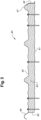
- FIG 2 shows one of the sandwich panels 40A of the façade element 1A, in perspective.
- This panel as each sandwich panel 40A of the façade element 1A, comprises an insulation material 43A sandwiched between an inner metallic sheet 41A and an outer metallic sheet 42A.
- outer and outer refer to the position of the façade element 1A on the building. So, the outer metallic sheet 42A is facing the outside of the building and the inner metallic sheet 41A is facing the inside of the building, when the façade element 1 is in position on the building.
- the insulation material 43A can be any material providing some insulation to the panel 40A. It can be, by way of non-restricting examples, polyurethane foam, polyisocyanurate foam, phenolic foam, mineral wool. According to a variant of the invention, the insulation material is a composite comprising a lower layer of mineral wool and an upper layer of foamed material.
- the inner and outer metallic sheets 41A and 42A can be made of steel, aluminum, copper or zinc. They are preferably made of previously galvanized and/or pre-coated steel to protect them against corrosion. Their thickness is low compared to their other dimensions. Generally speaking, for each of these sheets, the sheet thickness is 400 to 4000 times lower than its width.
- the inner and outer metallic sheets 41A and 42A of the sandwich panel 40A will preferably have been previously formed with the aid of any known forming method, including, by way of non-restricting examples, bending, forming, stamping and molding.
- a rib is understood to mean a projection formed on the surface of the sheet.
- the rib may have a trapezoidal shape or a rectangular, corrugated, sinusoidal or even omega shape, for example. It includes a top central part and two lateral wings.
- a stiffener is a rib of limited height, generally 10 to 30 times lower than a rib.
- a groove is understood to mean a recess formed on the surface of the panel. The groove can have shapes similar to the ones offered for ribs. Ribs, stiffeners or grooves are generally placed in parallel to longitudinal edges of the sheet notably to render the sheet more rigid.
- the inner and outer metallic sheets 41A and 42A have a substantially flat surface, with stiffeners.
- the depth of these ribs is smaller than one tenth of the thickness of the panel.
- metallic sheets with deeper ribs or structures could also be used, to build the sandwich panels of the façade element.
- the outer metallic sheet 41A is joined to the inner metallic sheet 42A by a first longitudinal edge 44A, and, on an opposite side of the first longitudinal edge 44A, by a second longitudinal edge 45A. Each of these longitudinal edges extends longitudinally, along the panel 40A.
- the sandwich panels 40A of the façade element 1A are assembled side-by-side, parallel to each other, onto the metal framework 2A.
- Each of these sandwich panels 40A interlocks with at least one adjacent sandwich panel 40A, along at least a part of one of its longitudinal edges 44A, 45A. More precisely, for each couple of adjacent sandwich panels 40A, the first longitudinal edge 44A of one of these two panels interlocks with the second longitudinal edge 45A of the other of these two adjacent panels. They interlock with each other in a watertight/airtight manner.
- each of these sandwich panel 40A is configured so that it can interlock with an adjacent, identical sandwich panel, either along its first longitudinal edge 44A, or along its second longitudinal edge 45A.
- each of these sandwich panels 40A comprises, on one of its longitudinal edges 44A, 45A, a male interlocking part, and on its other longitudinal edge 45A, 44A, a female interlocking part such that the male and female interlocking parts interlock into one another when two panels are assembled.
- first longitudinal edge 44A, and the second longitudinal edge 45A of each sandwich panel 40A have complementary, or at least substantially complementary shapes (see figure 2 ), so that the panel can interlock, on either of its sides, with another identical panel.
- first longitudinal edge 44A of the panel may be in the shape of a double male rail with two narrow longitudinal tenons
- second longitudinal edge 45A is in the shape of a double female rail, with two mortises in which the two longitudinal ribs of the first longitudinal edge 44A of another panel can be inserted.
- the first and second longitudinal edge may have (complementary) shapes different than in the case of figure 2 .
- each panel 40' may extend beyond one of the longitudinal edges of the panel to form a longitudinal lid 46' (in other words a kind of flap) configured to interlock with a complementary longitudinal rib 47' protruding on the outer face of another, adjacent panel.
- the longitudinal rib is parallel to one of the longitudinal edges of the adjacent panel, and is located close to this edge.
- each panel 40' comprises: on one side, the longitudinal lid 46' mentioned above, and, on the opposite side, the complementary longitudinal rib 47'.
- the longitudinal rib 47' may be trapezoidal, the longitudinal lid 46' having then a trapezoidal cross section (see figure 3 ).
- Each sandwich panel 40A of the façade element 1A is fastened to the metal framework 2A, for instance by screws (e.g.: self-drilling screws) passing through the panel 40A to engage with the metallic framework 2A.
- screws e.g.: self-drilling screws
- the assembly of sandwich panels 40A of the façade element 1A is delimited by an outer face 31A, an inner face 32A, a lower edge 33A, an upper edge 34A, a left edge 35A and a right edge 36A (see figure 1 ).
- the outer face 31A of the assembly is formed by all the outer metallic sheets 42A of the sandwich panels 40A of the assembly.
- the inner face 32A is formed by all the inner metallic sheets 43A of these sandwich panels 40A.
- the metal framework 2A is located on the inner side of the assembly of sandwich panels 40A, opposite to its outer face 31A.
- the terms “lower”, “upper”, “above”, “below”, “lowest”, “highest”, “top”, “bottom”, “left”, “right”... as used in this application refer to the positions and orientations of the different parts of the façade element when the latter is positioned vertically on a building structure, and fastened on this building structure (in its final position). More particularly, the terms “left” and “right” refer to the positions and orientations of the different parts of the façade element when the façade element, fastened on this building structure, is seen from the outside of the building.
- the outer face 31A, inner face 32A, lower edge 33A, upper edge 34A, left edge 35A and right edge 36A of the assembly of sandwich panels 40A are also referred to, indifferently, as the outer face 31A, inner face 32A, lower edge 33A, etc.... of the corresponding façade element.
- edges 33A, 34A, 35A, 36A of the façade element 1A are substantially plane. They are more particularly deprived of fastening means like the rail or lid mentioned above. Such plane edges may be obtained by cutting up longitudinally the sandwich panels located most on the periphery of the façade element 1A.
- the façade element 1A further comprises an upper waterproofing membrane 4A that covers up the upper edge 34A of the assembly of sandwich panels 40A (see figures 4 and 6 ).
- the upper waterproofing membrane 4A may, like here, cover the whole length of the upper edge 34A. This membrane is folded on each side of the upper edge 34A, and thus covers also an upper part of the outer face 31A of the assembly of sandwich panels, and an upper part of its inner face 32A.
- the upper waterproofing membrane 4A thus extends from the outer face 31A of the assembly 3A of sandwich panels, to the inner face 32A of this assembly.
- the upper waterproofing membrane 4A comprises a left upper overhang 41A extending beyond the left edge 35A of the assembly of sandwich panels 40A, and a right upper overhang 42A extending beyond the right edge 36A of the assembly.
- the upper waterproofing membrane 4A that covers up the upper edge 34A of the assembly of sandwich panels from side to side, prevents efficiently water from seeping into the insulation material 43A of the sandwich panels 40A.
- the upper waterproofing membrane 4A is made in one piece. It is flexible and waterproof. It may be made of a waterproof elastomeric material, such as Ethylene Propylene Diene Monomer rubber (usually referred to as "EPDM").
- EPDM Ethylene Propylene Diene Monomer rubber
- the upper waterproofing membrane 4A may have a thickness comprised between 0.3 and 2 millimeters.
- the left upper overhang 41A may extend, beyond the left edge 35A of the assembly of sandwich panels 40A, over a length comprised between 1 and 7 centimeters, for instance higher than 3 centimeters.
- the right upper overhang 42A may extend also, beyond the right edge 36 of the assembly of sandwich panels 40, over a length comprised between 1 and 7 centimeters, for instance higher than 3 centimeters.
- the left and right upper overhangs 41A, 42A have the same length l .
- a part of the upper waterproofing membrane 4A may be pressed against the inner face 32A of the assembly by the upper metallic section 22A of the metal framework 2A.
- the upper waterproofing membrane 4A may be sandwiched between the upper metallic section 22A and the inner face 32A of the assembly of sandwiched panels 40A, all along the upper metallic section 22A. Fixing the membrane on the assembly of sandwiched panels in this way is fast, convenient, and cost-effective.
- the upper waterproofing membrane 4A is further fixed on the assembly of sandwich panels 40A by gluing: the upper waterproofing membrane 4A is glued both on the upper part of the outer face 31A, and on the upper part of the inner face 32A of the façade element 1A.
- the façade element 1A comprises also a lower waterproofing membrane 5A, that extends along the lower edge 33A of the assembly of sandwich panels 40A, on the inner face 32A of this assembly.
- the lower waterproofing membrane 5A comprises:
- the lower waterproofing membrane 5A is made in one piece.
- the flap 53A and the left and right lower overhangs 51A and 52A designate different parts (extending beyond different edges of the assembly) of the same waterproofing membrane 5A or, in other words, of the same waterproof and flexible sheet.
- the lower waterproofing membrane 5A is flexible and waterproof. It may be made of a waterproof elastomeric material, such as Ethylene Propylene Diene Monomer rubber (usually referred to as "EPDM"). It may be in a material similar or identical to the one of the upper waterproofing membrane 34A.
- the low waterproofing membrane 35A may have, like the upper waterproofing membrane, a thickness comprised between 0.3 and 2 millimeters.
- a part of the lower waterproofing membrane 5A may be pressed against the inner face 32A of the assembly by the lower metallic section 21A of the metal framework 2A.
- the lower waterproofing membrane 5A may be sandwiched between the lower metallic section 21A and the inner face 32A of the assembly of sandwiched panels 40A.
- the lower waterproofing membrane 5A is further fixed on the assembly of sandwich panels 40A by gluing it against the lower part of the inner face 31A of the sandwich panel.
- the flap 53A extends beyond the lower edge 33A of the assembly of sandwich panels, over a distance d higher than or equal to the thickness t of the lower edge 33A of the assembly of sandwich panels.
- the ratio between the distance d of the flap 53A and the thickness t of the lower edge 33A of the assembly of sandwich panels is higher than 1.
- this ratio is lower than 3.
- the thickness t of the lower edge 33A of the assembly of sandwich panels is preferably higher than or equal to 4.0 cm.
- the thickness t is preferably lower than or equal to 30.0 cm.
- the thickness t is more preferably comprised between 7.0 cm and 25.0 cm.
- the flap 53A when assembling a façade 10 made of several such façade elements, the flap 53A can be arranged so that it extends from the bottom of the inner face of an upper façade element 1C, to the upper part of the outer face of a lower façade element 1A, thus making the junction between these two façade elements 1A, 1C waterproof.
- a flap arranged in this way allows water, that could have infiltrated the façade, to be efficiently discharged to the outside.
- the left lower overhang 51A may extend beyond the left edge 35A of the assembly of sandwich panels 40A over a length comprised between 1 and 7 centimeters, for instance higher than 3 centimeters.
- the right lower overhang 52A may extend also, beyond the right edge 36A of the assembly of sandwich panels 40A, over a length comprised between 1 and 7 centimeters, typically higher than 3 centimeters.
- the left and right lower overhangs 51A and 52A have the same length l (which is also the same as the length of the left and right upper overhangs 41A and 42A).
- the overhangs 51A, 52A of the lower waterproofing membrane 5A enable two adjacent façade elements to be joined together, in a watertight manner, while maintaining a lateral (horizontal) gap between them, as explained above about the upper overhangs 41A, 42A.
- the façade element 1A may be provided also with a side waterproofing membrane 9 fixed, for instance glued, on the inner face 32A of the façade element 1A and extending either on the right side of the façade element 1, beyond its right edge 36A, or on the left side of the façade element 1, beyond its left edge 35A (see figure 18 ; the side waterproofing membrane 9 of the façade element 1A is not represented in figures 6 and 7 for clarity).
- the side waterproofing membrane 9 is intended to close the lateral gap between two laterally adjacent façade elements 1A, 1B of a building façade.
- the side waterproofing membrane 9 is configured more precisely to extend from the inner face 32A of one of these two façade elements, to the inner face 32B of the other of these two façade elements, across the lateral gap mentioned above.
- the side waterproofing membrane 9 is substantially rectangular. It extends beyond the right edge 36A (or, alternatively, beyond the left edge) of the façade element, over a length that is higher than the length l of the overhangs 41A, 42A, 51A, 52A, as the side waterproofing membrane 9 is configured to extend up to another adjacent façade element, across the gap maintained between them.
- the width of the side waterproofing membrane 9 (that is to say its extent in a direction parallel to the upper or lower edge 33A, 34A of the façade element), may be comprised between 8 and 16 centimeters, for instance.
- the side waterproofing membrane 9 may be made of the same material than the upper and lower waterproofing membranes 4A, 5A, and may have the same thickness.
- the side waterproofing membrane 9 covers up a part of the upper waterproofing membrane 4A, so that they overlap with each other (see figure 18 ).
- the side waterproofing membrane 9 may be glued over a part of the upper waterproofing membrane 4A that extends below the upper metallic section 22A, and that is located on the right side or, alternatively, on the left side of the façade element 1A.
- the upper waterproofing membrane 4A extends beyond the upper metallic section 22A, towards the lower edge of the façade element, over 2 centimeters at least, preferably over more than 4 centimeters.
- the side waterproofing membrane 9 and the upper waterproofing membrane 4A thus overlap with each other in a tile-like manner, which provides an improved waterproofing.
- the side waterproofing membrane 9 covers up also a part of the lower waterproofing membrane 5A, in a similar manner.
- the side waterproofing membrane 9 may be glued over a part of the lower waterproofing membrane 5A that extends above the lower metallic section 21A, and that is located on the right side or, alternatively, on the left side of the façade element 1A.
- the lower waterproofing membrane 5A extends above the lower metallic section 21A, towards the upper edge of the façade element, over 2 centimeters at least, preferably over more than 4 centimeters.
- the side waterproofing membrane 9 is preferably fixed on the façade element 1A before positioning and fastening the façade element 1A to a building structure (for instance, during the factory assembling of the façade element). It is indeed more convenient and enables a better assembling precision than fixing this side membrane after the façade element had been fastened to the building structure (as some elements of the building structure, like inner walls or pillars, may obstruct the installation of this side membrane).
- the side waterproofing membrane 9 may be glued along its entire length on the façade element 1A, its upper and lower parts being thus glued over the upper and lower waterproofing membranes 4A, 5A (as explained above).
- the side waterproofing membrane 9 may also be glued on the façade element 1A only along a part of its length, without gluing its upper and lower parts so that other waterproofing membranes can be inserted between the side waterproofing membrane 9 and the upper or lower waterproofing membranes 4A, 5A, during the process of assembling of the building façade.
- the inner and outer faces 32A, 31A of the assembly of sandwich panels 40A are full, solid, with no aperture.
- there may be one or more apertures in the façade element to allow the installation of one or more windows or other opening panels, for instance.
- These apertures could be equipped with appropriate joinery and/or sealing elements, for instance with window carpentry, so that the façade element, once provided with one or more windows, or doors or other opening panels, remains watertight.
- the apertures mentioned above could be obtained by cutting up one or several of the sandwich panels of the façade element.
- the joinery and carpentry mentioned above is typically fixed on the façade element 1 before positioning and fastening the façade element to a building structure (for instance, during the factory assembling of the façade element).
- the façade element 1A of figure 1 can be fastened to the main structure of a building, with other identical or similar façade elements, to build a façade of the building.
- Figures 16 and 17 are partial section views of an illustrative embodiment of a such a building façade 10.
- This façade 10 comprises at least ( figure 12 ):
- the four façade elements 1A, 1B, 1C, 1D are identical, or essentially identical to the façade element 1A of figure 1 .
- the identical or corresponding elements of these different façade elements are labeled using the same reference signs, followed respectively by the letters "A”, “B”, “C” and “D” (for instance, the upper edges of the respective assemblies of sandwich panels of these four façade elements are labeled using the following reference signs: 34A, 34B, 34C and 34D, respectively).
- This exemplary embodiment will allow one to understand the specific technique employed, according to the invention, to join together different façade elements of a same façade, in a watertight manner.
- this technique can be applied to build façades having a number of façade elements different than four (in particular higher than four), or to build façades made of façade elements different from the one represented in figure 1 as long as the façade elements employed are still provided with an upper and a lower waterproofing membrane like the ones described above.
- the second façade element 1B is positioned on the right of the first façade element 1A. So, the right edge 36A of the first façade element 1A faces the left edge 35B of the second façade element 1B, these two edges 36A, 35B being parallel to each other (see figure 12 and 17 ).
- the third façade element 1C is positioned above the first façade element 1A.
- the lower edge 33C of the third façade element 1C faces the upper edge 34A of the first façade element 1A, these two edges being parallel to each other.
- the fourth façade element 1D is positioned above the second façade element 1B, and on the right of the third façade element 1C.
- the lower edge 33D of the fourth façade element faces the upper edge 34B of the second façade element 1B, these two edges 33D, 34B being parallel to each other.
- the left edge 35D of the fourth façade element 1D faces the right edge 36C of the third façade element 1C, these two edges 35D, 36C being parallel to each other.
- the four façade elements 1A, 1B, 1C and 1D are slightly spaced apart from each other: the assemblies of sandwich panels of these different façade elements do not come into contact with each other.
- the right edges 36A, 36C of the left façade elements 1A and 1C are separated from the left edges 35B, 35D of the right façade elements 1B and 1D by a lateral gap g (see figure 17 ).
- This gap g may be comprised between 1 and 10 centimeters. It is preferably higher than 2, or even 4 centimeters.
- the lateral gap g is equal to the length l of the overhangs 41A, 51A, 42B, ... of the waterproofing membranes 4A, 4B, 5C, 5D of the façade elements (still, the gap g could alternatively be possibly slightly higher than said length l ).
- Maintaining such a lateral spacing between adjacent façade elements i.e. : having this lateral gap g ) makes the assembling of the façade easier than the assembling a gap-less structure, as it provides a greater freedom regarding the positioning of the façade elements on the building (in other words, it allows higher, less stringent mechanical tolerances than with a gap-less structure).
- having a gap that wide makes the filling of the gap with insulating material easier, and enables the waterproofing membranes of the various façade elements to overlap with each other over a wide area, at the junction between adjacent façade elements.
- the lower edges 33C, 33D of the upper façade elements 1C, 1D are separated from the upper edges 34A, 34B of the lower façade elements 1A, 1B by a vertical gap g' (see figure 16 ).
- the vertical gap g' may be comprised between 1 and 5 centimeters, for instance. It is preferably higher than 2 centimeters. Maintaining this vertical gap provides the same benefits as maintaining the lateral gap mentioned above.
- junction and waterproofing between laterally adjacent façade elements that is to say between the first and second façade elements 1A, 1B, or between the third and fourth façade elements 1C, 1D) will be presented first.
- junction and waterproofing between façade elements placed one above the other will be presented in a second step.
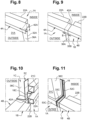
- the right upper overhang 42A of the first façade element 1A and the left upper overhang 41B of the second façade element 1B overlap at least partially each other.
- the lateral gap a equals the length l of these overhangs, and these two overhangs thus overlap completely each other (they overlap each other over their entire extent).
- the left upper overhang 41B is in contact with the right upper overhang 42A. They are even preferably glued together.
- the right upper overhang 42A overlaps the left upper overhang 41B and covers up the left upper overhang 41B.
- the left upper overhang 41B overlaps the right upper overhang 42A and covers up the right upper overhang 42A.
- the waterproofing upper membranes 4A and 4B are thus joined to each other, in a watertight manner, in spite of the lateral gap g , to form a kind of continuous, longer membrane extending along the façade 10.
- the lateral gap g between the first and second façade elements 1A, 1B is closed, on the inner side of the façade, by a first side waterproofing membrane, namely by the side waterproofing membrane 9 that has been described above, (which has been preferably fixed on the first façade element 1A during its factory assembling, prior to its positioning on the building).
- the first side waterproofing membrane 9 is fixed to the right edge of the first façade element 1A as described above, when presenting the façade element 1A itself.
- the first side waterproofing membrane 9 is fixed to the second façade element 1B.
- the first side waterproofing membrane 9 is more precisely glued on the inner face 32B of the second façade element, in the vicinity of its left edge 35B.
- the top of the first side waterproofing membrane 9 overlaps with a part of the upper waterproofing membrane 4B of the second façade element 1B, just like it overlaps with a part of the upper waterproofing membrane 4A of the first façade element 1A (this last overlapping having been described above when presenting the façade element 1A). And, similarly, the bottom of the first side waterproofing membrane 9 overlaps with a part of the lower waterproofing membrane 5B of the second façade element 1B.
- the lateral gap between the adjacent façade elements 1A and 1B is filed with an insulating material 17, for instance with some mineral wool (see figure 17 ).
- the lateral gap is closed, on the outer side of the façade, by a profiled member 11 extending from the outer face 31A of the first façade element to the outer face 31B of the second façade element (see figure 17 ).
- the right upper overhang 41C of the third façade element 1C and the left upper overhang 41D of the fourth façade element 1D overlap at least partially each other. Here, they overlap completely each other. They are in close contact with each other. Here, they are even preferably glued to each other.
- the lower waterproofing membranes 5C and 5D are also joined to each other in a watertight manner, thanks to their overhanging parts 52C, 51D, to form a kind of continuous, longer membrane extending along the façade 10.
- the right lower overhang 52C of the third façade element 1C and the left lower overhang 51D of the fourth façade element 1D overlap each other (here, they overlap completely each other). These two overhangs 52C, 51D are in close contact with each other. They are glued together (the glue 16 employed to glue them together is represented in figures 11 and 12 by hatching).
- the left lower overhang 51D of the fourth façade element 1D overlaps the right lower overhang 52C of the third façade element 1C.
- the right lower overhang 52C of the third façade element 1C could overlap the left lower overhang 51D of the fourth façade element 1D.
- the lateral gap between the third and fourth façade elements 1C, 1D is closed, on the inner side of the façade, with a second side waterproofing membrane 9', identical (or at least similar) to the first side waterproofing membrane 9.
- the second side waterproofing membrane 9' is attached, here glued, on the inner faces 32C, 32D of both the third and fourth façade elements 1C, 1D (see figure 15 ). According to one variant, this second side waterproofing membrane 9' is attached partially on the upper and lower waterproofing membranes 4C, 4D, 5C, 5D of the façade elements 1C, 1D joined by this second side waterproofing membrane 9', like explained above for the first side waterproofing membrane 9.
- the second side waterproofing membrane 9' is attached on the inner faces 32C, 32D without being attached to the upper and lower waterproofing membranes 4C, 4D, 5C, 5D. In that case, there is no restriction on how the lower overhangs overlap each other.
- the lateral gap between the third and fourth façade elements 4C, 4D is closed by a profiled member 11 extending from the outer face 31C of the third façade element to the outer face 31D of the fourth façade element (like the lateral gap between the first and second façade element).
- This lateral gap too is filed with an insulating material, for instance with some mineral wool.
- This later waterproofing is achieved, inter alia, by means of the two lower waterproofing membranes 5C and 5D of the upper façade elements 1C and 1D.
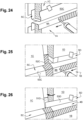
- the lower waterproofing membrane 5C When installing the upper façade element 1C on the building structure, one folds the lower waterproofing membrane 5C to bring the flap 53C of this membrane close to the lower edge 33C of this façade element (to maintain the flap 53C in this position, the lower end of the flap may be temporarily fixed to the outer face of the façade element 1C using adhesive tape, for instance, see figures 24 and 25 ).
- the third façade element 1C in then placed in its final position on the building structure and fastened to it. And then, the part of flap 53C that extend outside the façade is folded down on the upper part of the outer face of the lower façade element 1A.
- the flap 53C of the lower waterproofing membrane 5C extends from the inside of the façade, to its outside.
- the flap 53C extends more precisely from the inner face 32C of the third façade element 1C, to the outer face 31A of the first façade element 1A (the lower waterproofing membrane 5C having then the shape of a kind of stair step, or the shape of a kind of slide directed downwards, and towards the outside of the façade).
- This configuration allows water, that could have infiltrated the façade, to be efficiently discharged to the outside.
- the flap 53C is put in contact with a part of the upper waterproofing membrane 4A of the first façade element, all along this membrane 4A, and covers up this part of the upper waterproofing membrane 4A, thus joining the third façade element 1C and the first façade element 1A in a particularly watertight manner. More precisely:
- a longitudinal, rain protective profiled lid 7C is fastened to a bottom part of the outer face 31C of the third façade element 1C (see figure 16 ).
- the rain protective profiled lid 7C extends longitudinally along the lower edge 33C of the third façade element 1C.
- This rain protective profiled lid is fastened, for instance by means of screws, to the bottom part of the outer face 31C and it extends outwardly and downwardly from the outer face 31C, beyond the lower edge 33C of the third façade element 1C.
- the rain protective profiled lid 7C thus prevents rainwater from entering the space that extends between the lower façade element 1A and the upper façade element 1C.
- the rain protective profiled lid 7C is fastened directly to the outer face 31C of the third façade element 1C. Still, in other embodiments, the rain protective profiled lid could be fastened to additional equipment such as an outer cladding, which, in turn, is fastened to the outer face of the assembly of sandwich panels of the façade element (in which case the rain protective profiled lid is still fastened to the outer face of the façade element, but non-directly).
- the rain protective profiled lid 7C may be obtained, like here, by bending and stamping, from a metallic sheet.
- the rain protective profiled lid 7C may comprise successive sheet portions (each portion being substantially plane), namely:
- the façade 10 preferably comprises also fire deflectors 8C, 8D, each extending across the gap that separates the lower façade elements 1A, 1B from their upper counterpart 1C, 1D.
- Each deflector may be made, like here, of a formed metallic sheet. It is fastened to the inner face 32C, 32D of the upper façade element considered, at the bottom of it, preferably on a mounting angle 18C attached on the underside of the metal framework 2 (see figure 10 ). It extends across said gap, up to the outside of the assembly of sandwich panels.
- each fire deflector 8C comprises:
- the fixing bracket 80C is fastened, for instance bolted, to the mounting angle 18C.
- the lower, free end of the second portion 82C of the fire deflector 8C is preferably supported by a folded rim made at the lower, free end of the folded portion 72C of the rain protective profiled lid 7C.
- Each of the upper façade elements 1C, 1D is preferably isolated, along its entire length (that is to say all along its lower edge), from its lower counterpart 1A, 1B, by one or more of these fire deflectors 8C, 8D.
- Each of these fire deflectors may extend all along the corresponding façade element, or along just a part of this façade element (in this last case, several fire deflectors are provided to each façade element, to isolate the two façade elements from each other over their entire length).
- a compressible strip for instance a watertight compressible strip may also be arranged below the façade element 1C, along at least a part of the lower edge 33C of the assembly of sandwich panels of this façade element, for instance in contact with this lower edge.
- This compressible strip 6C may be used as a thermal insulation, to fill the vertical gap maintained between two façade elements 1A, 1C placed one above the other.
- the compressible strip may be a closed-cell plastic foam seal, for instance (like a closed-cell polyvinyl chloride foam seal).
- the compressible strip 6C is typically arranged on the façade element 1A after the façade element has been positioned and fastened to a building structure.
- the compressible strip 6C may be made in one piece, or it may comprise several shorter sections, to facilitate its insertion between the two façade elements 1A, 1C in question (see figure 31 , for instance).
- the façade elements could be provided with other additional equipment, fixed on the outer side of the façade element considered, such as outer claddings.
- the rain protective profiled lid 7C participates to the waterproofing of the façade.
- the protection of the building against rain and runoff water is thus achieved by means of two different barriers:
- the first barrier is not airtight: it allows air communication between the outside and the space between the lower façade element 1A and the upper façade element 1C. And these two barriers are slightly spaced from each other.
- the vertical gap g' is high enough that the fire deflector 8C does not come into contact with the lower façade element 1A.
- the fire deflector 8C is thus spaced apart from the upper edge 34A of the first façade element.
- the space thus provided between these elements plays the role of a pressure balancing chamber, enabling to balance the pressure of air on the inner side of the façade, and the pressure of air on the outer side of the façade.
- junction and waterproofing between the second façade element 1B and the fourth façade element 1D is identical, or at least similar to what has be presented just above for junction of the first façade element 1A with the third façade element 1C.
- junction node where the four façade elements 1A, 1B, 1C and 1D are joined to each other, is set up so that the waterproofing membranes 4A, 4B, 5C, and 5D overlap in a tile-like arrangement.
- the tile-like arrangement can be as follows:
- first and second side waterproofing membranes 9 and 9' their upper and lower parts cover up the upper, and lower waterproofing membranes respectively, as already described.
- This overall tile-like arrangement contributes to an efficient waterproofing of the node in question.
- This tile-like arrangement is the one implemented when the side waterproofing membrane 9 is fixed on the right edge 36A of the first façade element 1A during its factory assembling (before fastening the façade elements to the building structure) and is fixed partially on the upper and lower waterproofing membranes (glued over a part of the upper and over a part of the lower waterproofing membranes, for instance).
- This tile-like arrangement is thus the one implemented when the side waterproofing membrane 9 is prefixed along its entire length on the inner side 32A of the façade element 1A. In this case, it is this tile-like arrangement that is implemented because the left upper overhang 41B could not be arranged over the right upper overhang 42A.
- the right lower overhang 52C could not be arranged over the left lower overhang 51D, as the side waterproofing membrane 9 is glued, over its entire length, on the right side of the façade element 1A.
- the detailed sequence of this tiling can be different:
- This tile-like arrangement is the one implemented when the side waterproofing membrane 9 is fixed on the left edge 35 of the first façade element 1 during its factory assembling and is fixed partially on the upper and lower waterproofing membranes (glued over a part of the upper and over a part of the lower waterproofing membranes, for instance).
- the side waterproofing membrane 9 is not fixed on the upper and lower waterproofing membranes or not fixed on one edge of the first façade element 1 during its factory assembling, other tile-like arrangements than the ones described above can be implemented.
- the two tile-like arrangements described above can be mixed.
- the different waterproofing membranes may overlap each other so that:
- the façade elements 1A, 1B, 1C, 1D are fastened to the building structure by means of their respective metal frameworks, more specifically by mean of their lower 21A, 21B, 21C, 21D and upper 22A, 22B, 22C, 22D metallic sections.
- the concrete slabs 14, 14' of the building are equipped with mounting plates 13, fastened to the slab, that protrudes from these slabs 14, 14', towards the outside of the building ( figure 16 ).
- the lower metallic section of a given façade element (for instance the lower metallic section 21C of the third façade element 1C, see figure 16 ) rests on at least two such mounting plates 13, which support the façade element.
- the upper metallic section of the façade element is linked to mounting plates protruding from the slab 14' of the above floor, this connection being achieved by means of metallic axes, here.
- Each of these axes extends substantially vertically and passes through one of the mounting plates, and then through corresponding holes of the upper metallic section of the façade element (see the metallic axis 12 of figure 16 , for instance, which retains the upper part of the first façade element 1A).
- the upper end of the axis comprises a flange, which is sandwiched between the mounting plate 13 itself and a metallic section of another façade element placed above (and supported by this mounting plate), which secure the metallic axis in question.
- a building façade made of façade elements according to the invention is assembled from bottom to top (for instance floor by floor).
- the lowest floor to be provided with façade elements for instance the ground floor, is first equipped, at least partially, with the façade elements to be fastened between this lowest floor and the floor above (to provide the ground floor with an external wall).
- the assembling of the façade may continue on the floor above, by positioning and fastening to the building two or more upper façade elements each positioned above one of the façade elements of the floor below.
- the lowest floor in question may be fully equipped with façade elements before starting to provide the floor above with façade elements.
- the assembling of façade elements on floor above may start when at least two adjacent façade elements have been installed on the lowest floor, even if the lowest floor is not fully equipped. In this case, the building of the façade may then continue in parallel on the lowest floor and on the floor above.
- FIGS 19 to 31 represent different steps of an assembling of four adjacent façade elements, that enable to obtain a façade like the one that has been described in detail above.
- This façade comprises:
- first, second, third and fourth façade elements 1A, 1B, 1C, 1D are identical, or at least similar to the ones that have been described above. They comprise openings (windows and/or entrance doors). Apart from their openings, these four façade elements 1A, 1B, 1C, 1D are identical to each other. These façade elements and their different parts will be referred to using the same reference signs as before (for instance, their respective upper waterproofing membranes will be referred to as 4A, 4B, 4C and 4C, as before). Each of these façade elements 1A, 1B, 1C, 1D is provided with the side waterproofing membrane 9, 9' that has been described above.
- each side waterproofing membrane 9, 9' is attached on the left side of the corresponding façade element 1A, 1B, 1C, 1D, here.
- the side waterproofing membrane 9, 9' is attached to the corresponding façade element before fastening this façade element onto the building structure (the membrane is attached during the factory assembling of the façade element).
- the side waterproofing membrane 9, 9' is attached on the inner face of the façade element 1A, 1B, 1C, 1D without being attached to the upper and lower waterproofing membranes of this façade element.
- the assembling technique described below, with reference to figures 19 to 31 can be applied to build facades having a different number of facade elements than in figures 19 to 31 (in particular, with more than two façade elements for each floor), or may comprise a different number of steps (in particular additional steps not described here), or steps arranged according to a different assembling sequence.
- the assembling process of figures 19 to 31 starts by a step of positioning the first façade element 1A on the building structure 15 and fastening it to this structure (see figure 19 ).
- the first façade element 1A is fastened to this structure as explained above : its lower metallic section 21A is supported by (rest on) the mounting plates 13 that are fixed to the ground-floor concrete slab 14 of the building, while its upper metallic section 22A is retained to the building thanks to the metallic axis 12 that passes through the mounting plates 13 fixed to the first-floor concrete slab 14'.
- the second facade element 1B is then positioned on the right of the first façade element 1A ( figure 20 ) and fastened to the building structure 15 using the same fastening technique as for the first facade element.
- the second facade element 1B is positioned more precisely with its left edge 35B facing the right edge 36A of the first facade element 1A, these two edges 36A, 35B being parallel to each other, and separated by the lateral gap g mentioned above.
- the left upper overhang 41B of the upper waterproofing membrane 4B of the second façade element 1B is then placed over the right upper overhang 42A of the upper waterproofing membrane 4A of the first façade element 1A and glued to it ( figure 21 ).
- the third façade element 1C is then positioned above the first facade element 1A, and fastened to the building structure 15, using the same fastening technique as before ( figure 22 ).
- the lower metallic section 21C of the third façade element 1C rests on mounting plates 13 that protrude from the first-floor slab 14'.
- its upper metallic section 22C is linked to mounting plates 13 fixed to a second-floor slab using metallic axis passing through holes made in the upper metallic section 22C, like explained above.
- the third façade element 1C is positioned with the lower edge 33C of the third facade element 1C facing the upper edge 34A of the first facade element 1A, these two edges being parallel to each other, and being separated by the vertical gap g ' mentioned above.
- the third façade element 1C is aligned vertically with the first façade element 1A : the left edge 35C of the third façade element 1C is located in the extension of the left edge 35A of the first façade element 1A, vertically above it (vertically aligned with it), and so it is for the left edges 36A, 36C of these two façade elements.
- the third façade element may alternatively be positioned over the first façade element while being laterally offset (in which case its left edge 35C is not aligned with the left edge 35A of the first façade element 1A).
- the fourth façade element 1D is then positioned above the second facade element 1B and fastened to the building structure 15 using the same fastening technique as before ( figure 23 ).
- the fourth façade element 1D is positioned with its lower edge 33D facing the upper edge 34B of the second facade element 1B, these two edges 33D, 34B being parallel to each other, separated by the vertical gap g '.
- the fourth façade element 1D is aligned vertically with the second façade element 1B.
- the fourth façade element 1D is positioned with its left edge 35D facing the right edge 36C of the third facade element, these two edges being parallel to each other, separated by the lateral gap g .
- the flap 53C of the lower waterproofing membrane 5C of the third façade element 1C (which was, until then, attached to the outer face of the third façade element 1C, using tape) is folded down onto the outer face 31A of the first façade element 1A ( figure 24 ). It is more precisely folded down onto the part of the upper waterproofing membrane 4A of the first facade element 1A that extends on the outer face 31A of this façade element, and it is glued to this part of the upper waterproofing membrane 4A, all along the façade element 1A.
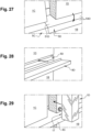
- the flap 53D of the lower waterproofing membrane 5D is then folded down onto the outer face 31B of the second façade element 1B ( figure 27 ). It is more precisely folded down onto the part of the upper waterproofing membrane 4B of the second façade element 1B that extends on the outer face 31B of this façade element and glued to this part of the upper waterproofing membrane 4B, all along the façade element 1B.
- the second side waterproofing membrane 9' that comes already mounted (glued) on the inner face 32D of the fourth façade element 1D, on its left side, is deployed and glued against the inner face 32C of the third façade element 1C (on the right side of this face 32C), to close the back of the lateral gap between these two façade elements 1C, 1D in a watertight manner.
- the fire deflectors 8C, 8D are then inserted in the vertical gap that separates the upper façade elements 1C, 1D from the lower façade elements 1A, 1B ( figure 28 ), and fastened to the inner faces of the upper façade elements 1C, 1D.
- the insulating material 17 is then inserted in the lateral gaps that separate the left façade elements 1A, 1C from the right façade elements 1B, 1D ( figure 29 ).
- the compressible strips 6D, 6C are inserted in the vertical gaps mentioned above, between the fire deflectors 8C, 8D and the lower edges 33C, 33D of the upper façade elements 1C, 1D ( figure 30 ).
- the rain protective profiled lids 7C, 7D are then fastened on the outer faces 31C, 31D of the upper façade elements, along the lower end of these faces 31C, 31D ( figure 31 ).
- the flap 53C of the lower waterproofing membrane 5C of the third façade element 1C could be deployed and fixed to the upper waterproofing membrane 4A of the first façade element 1A before fastening the fourth façade element on the building structure (instead of gluing these two membranes together after the fourth façade element had been fastened to the building structure).
- the first side waterproofing membrane 9 could be fixed to the first façade element 1A after having positioned and fastened the two upper façade elements 1C, 1D, instead of doing it before.
- the first façade element 1A is first fastened to the building structure, and then, the second façade element 1B is positioned on the right side of the first façade element 1A and fastened to the building structure.
- the second façade element could also be fastened first to the building structure, the rest of the assembling process remaining unchanged.
Landscapes
- Engineering & Computer Science (AREA)
- Architecture (AREA)
- Civil Engineering (AREA)
- Structural Engineering (AREA)
- Physics & Mathematics (AREA)
- Electromagnetism (AREA)
- Building Environments (AREA)
- Finishing Walls (AREA)
Claims (14)
- Fassadenelement (1A), umfassend:- einen Metallrahmen (2A), umfassend mindestens zwei metallische Längsabschnitte (21A, 22A) und zwei metallische Querabschnitte (23A, 24A), die alle miteinander zusammengebaut werden, um einen im Wesentlichen rechteckigen Rahmen zu bilden,- eine Anordnung (3A) von Sandwichplatten (40A; 40'), jeweils umfassend ein Isoliermaterial (43; 43'), das zwischen einem inneren Metallblech (41A; 41') und einem äußeren Metallblech (42A; 42') angeordnet ist, wobei jede Sandwichplatte (40A; 40') an dem Metallrahmen (2A) befestigt und mit mindestens einer angrenzenden Sandwichplatte (40A, 40') entlang mindestens eines Teils eines ihrer Ränder (44A, 45A; 44', 45') verriegelt ist, sodass die Anordnung (3A) durch eine Außenfläche (31A), eine Innenfläche (32A), einen unteren Rand (33A), einen oberen Rand (34A), einen linken Rand (35A) und einen rechten Rand (36A) begrenzt ist,das Fassadenelement (1A) ferner umfassend:- eine obere Abdichtungsmembran (4A), die den oberen Rand (34A) der Anordnung von Sandwichplatten bedeckt und sich sowohl über mindestens einen oberen Teil der Außenfläche (31A) als auch über mindestens einen oberen Teil der Innenfläche (32A) erstreckt, die obere Abdichtungsmembran (4A) ferner umfassend einen linken oberen Überstand (41A), der sich über den linken Rand (35A) hinaus erstreckt, und einen rechten oberen Überstand (42A), der sich über den rechten Rand (36A) hinaus erstreckt,- eine untere Abdichtungsmembran (5A), die sich entlang des unteren Rands (33A) der Anordnung auf der Innenfläche (32A) erstreckt und umfassend:∘ eine Klappe (53A), die sich über den unteren Rand (33A) hinaus in einem Abstand (d) erstreckt, der größer ist als die Stärke (t) des unteren Rands (33A) ist,∘ einen linken unteren Überstand (51A), der sich über den linken Rand (35A) hinaus erstreckt,∘ einen rechten unteren Überstand (52A), der sich über den rechten Rand (36A) hinaus erstreckt.
- Fassadenelement (1A) nach Anspruch 1, wobei die mindestens zwei metallischen Längsabschnitte einen oberen metallischen Abschnitt (22A) und einen unteren metallischen Abschnitt (21A) umfassen, wobei mindestens ein Teil der oberen Abdichtungsmembran (4A) durch den oberen metallischen Abschnitt (22A) gegen die Innenfläche (32A) der Anordnung (3A) gepresst wird, und wobei mindestens ein Teil der unteren Abdichtungsmembran (5A) durch den unteren metallischen Abschnitt (21A) gegen die Innenfläche (32A) der Anordnung gepresst wird.
- Fassadenelement (1A) nach Anspruch 1 oder 2, ferner umfassend eine seitliche Abdichtungsmembran (9), die an der Innenfläche (32A) der Anordnung (3A) von Sandwichplatten (40A; 40') angebracht ist, wobei:- die seitliche Abdichtungsmembran (9) entlang mindestens eines Teils des linken Rands (35A) der Anordnung (3A) von Sandwichplatten angebracht ist und sich über den linken Rand (35A) hinaus auf einer linken Seite der Anordnung von Sandwichplatten erstreckt, oder wobei- die seitliche Abdichtungsmembran (9) entlang mindestens eines Teils des rechten Rands (36A) der Anordnung (3A) von Sandwichplatten angebracht ist und sich über den rechten Rand (36A) hinaus auf einer rechten Seite der Anordnung von Sandwichplatten erstreckt.
- Fassadenelement (1A) nach einem der Ansprüche 1 bis 3, umfassend einen längs verlaufenden, profilierten Regenschutzdeckel, der sich in Längsrichtung entlang mindestens eines Teils des unteren Rands (33A) der Anordnung (3A) von Sandwichplatten erstreckt, der an der Außenfläche (31A) der Anordnung von Sandwichplatten befestigt ist und der sich über den unteren Rand (33A) der Anordnung hinaus nach außen und unten erstreckt.
- Gebäudefassade (10), umfassend ein erstes (1A), ein zweites (1B), ein drittes (1C) und ein viertes Fassadenelement (1D) nach einem der Ansprüche 1 bis 4, wobei das erste, das zweite, das dritte und das vierte Fassadenelement (1A, 1B, 1C, 1D) an einer Gebäudestruktur (15) befestigt sind,- der rechte Rand (36A) des ersten Fassadenelements (1A) dem linken Rand (35B) des zweiten Fassadenelements (1B) zugewandt ist, der rechte obere Überstand (42A) des ersten Fassadenelements (1A) und der linke obere Überstand (41B) des zweiten Fassadenelements (1B) einander zumindest teilweise überlappen und einen Spalt (g) zwischen dem ersten und dem zweiten Fassadenelement (1A, 1B) aufrechterhalten,- der untere Rand (33C) des dritten Fassadenelements (1C) dem oberen Rand (34A) des ersten Fassadenelements (1A) zugewandt ist, wobei sich die Klappe (53C) des dritten Fassadenelements (1C) von der Innenfläche (32C) des dritten Fassadenelements (1C) zu der Außenfläche (31A) des ersten Fassadenelements (1A) erstreckt,- der rechte Rand (36C) des dritten Fassadenelements (1C) dem linken Rand (35D) des vierten Fassadenelements (1D) zugewandt ist, wobei der rechte untere Überstand (52C) des dritten Fassadenelements (1C) und der linke untere Überstand (51D) des vierten Fassadenelements (1D) einander zumindest teilweise überlappen, während ein Spalt (g) zwischen dem dritten und dem vierten Fassadenelement (1C, 1D) aufrechterhalten bleibt,- der untere Rand (33D) des vierten Fassadenelements (1D) dem oberen Rand (34B) des zweiten Fassadenelements (1B) zugewandt ist, wobei sich die Klappe (53D) des vierten Fassadenelements (1D) von der Innenfläche (32D) des vierten Fassadenelements (1D) zu der Außenfläche (31B) des zweiten Fassadenelements (1B) erstreckt,- wobei der Spalt (g) zwischen dem ersten und dem zweiten Fassadenelement (1A, 1B) mit einer ersten seitlichen Abdichtungsmembran (9) geschlossen wird, die an den Innenflächen (32A, 32B) sowohl des ersten als auch des zweiten Fassadenelements (1A, 1B) angebracht ist,- der Spalt (g) zwischen dem dritten und vierten Fassadenelement (1C, 1D) mit einer zweiten seitlichen Abdichtungsmembran (9') geschlossen wird, die an den Innenflächen (32C, 32D) sowohl des dritten als auch des vierten Fassadenelements (1C, 1D) angebracht ist.
- Gebäudefassade (10) nach Anspruch 5, wobei:- der linke untere Überstand (51D) des vierten Fassadenelements (1D) zumindest teilweise den rechten unteren Überstand (52C) des dritten Fassadenelements (1C) überdeckt, der rechte untere Überstand (52C) des dritten Fassadenelements zumindest teilweise den rechten oberen Überstand (42A) des ersten Fassadenelements (1A) überdeckt, und der rechte obere Überstand (42A) des ersten Fassadenelements (1A) zumindest teilweise den linken oberen Überstand (41B) des zweiten Fassadenelements (1B) überdeckt, oder wobei- der rechte untere Überstand (52C) des dritten Fassadenelements (1C) zumindest teilweise den linken unteren Überstand (51D) des vierten Fassadenelements (1D) überdeckt, der linke untere Überstand (51D) des vierten Fassadenelements (1D) zumindest teilweise den linken oberen Überstand (41B) des zweiten Fassadenelements (1B) überdeckt, und der linke obere Überstand (41B) des zweiten Fassadenelements (1B) zumindest teilweise den rechten oberen Überstand (42A) des ersten Fassadenelements (1A) überdeckt.
- Gebäudefassade (10) nach Anspruch 5, wobei:- der linke untere Überstand (51D) des vierten Fassadenelements (1D) zumindest teilweise den rechten unteren Überstand (52C) des dritten Fassadenelements (1C) überdeckt, der rechte untere Überstand (52C) des dritten Fassadenelements zumindest teilweise den linken oberen Überstand (41B) des zweiten Fassadenelements (1B) überdeckt, und der linke obere Überstand (41B) des zweiten Fassadenelements zumindest teilweise den rechten oberen Überstand (42A) des ersten Fassadenelements (1A) überdeckt, oder wobei- der rechte untere Überstand (52C) des dritten Fassadenelements (1C) den linken unteren Überstand (51D) des vierten Fassadenelements (1D) zumindest teilweise überdeckt, der linke untere Überstand (51D) des vierten Fassadenelements (1D) zumindest teilweise den rechten oberen Überstand (42A) des ersten Fassadenelements (1A) überdeckt, und der rechte obere Überstand (42A) des ersten Fassadenelements zumindest teilweise den linken oberen Überstand (41B) des zweiten Fassadenelements (1B) überdeckt.
- Gebäudefassade (10) nach Anspruch 5 oder 6, wobei der Spalt (g) zwischen dem ersten und dem zweiten Fassadenelement (1A, 1B) und der Spalt (g) zwischen dem dritten und dem vierten Fassadenelement (1C, 1D) jeweils eine Breite von mindestens 4 Zentimetern aufweisen und jeweils mit einem Isoliermaterial (17) gefüllt sind.
- Gebäudefassade (10) nach einem der Ansprüche 5 bis 7, wobei ein vertikaler Spalt (g') zwischen dem ersten und dem dritten Fassadenelement (1A, 1C), und zwischen dem zweiten und dem vierten Fassadenelement (1B, 1D) aufrechterhalten wird, die Fassade (10) ferner umfassend:- einen oder mehrere Brandabweiser (8C), die an einem unteren Teil der Innenfläche (31C) des dritten Fassadenelements (1C) befestigt sind, wobei sich jeder Brandabweiser (8C) quer über den vertikalen Spalt bis zu der Außenseite der Anordnung von Sandwichplatten des dritten Fassadenelements erstreckt, um das dritte Fassadenelement (1C) von dem ersten Fassadenelement (1A) zu isolieren, und- einen oder mehrere Brandabweiser (8D), die an einem unteren Teil der Innenfläche (31D) des vierten Fassadenelements (1D) befestigt sind, wobei sich jeder dieser Brandabweiser (8D) quer über den vertikalen Spalt bis zu der Außenseite der Sandwichplattenanordnung des vierten Fassadenelements erstreckt, um das vierte Fassadenelement (1D) von dem zweiten Fassadenelement (1B) zu isolieren.
- Verfahren zum Zusammenbauen einer Gebäudefassade, umfassend:- (i) Bereitstellen mindestens eines ersten (1A), eines zweiten (1B), eines dritten (1C) und eines vierten Fassadenelements (1D) nach einem der Ansprüche 1 bis 4,- (ii) Positionieren und Befestigen des ersten Fassadenelements (1A) an einer Gebäudestruktur (15),- (iii) Positionieren des linken Rands (35B) oder des rechten Rands des zweiten Fassadenelements (1B) entlang des rechten Rands (36A) bzw. des linken Rands des ersten Fassadenelements (1A), sodass der rechte obere Überstand (42A) bzw. der linke obere Überstand, des ersten Fassadenelements (1A) und der linke obere Überstand (41B) bzw. der rechte obere Überstand des zweiten Fassadenelements (1B) einander zumindest teilweise überlappen, während ein Spalt (g) zwischen dem ersten und dem zweiten Fassadenelement (1A, 1B) aufrechterhalten bleibt,- (iv) Schließen des Spalts (g) zwischen dem ersten und dem zweiten Fassadenelement (1A, 1B) mit einer ersten seitlichen Abdichtungsmembran (9), die an den Innenflächen (32A, 32B) sowohl des ersten als auch des zweiten Fassadenelements (1A, 1B) angebracht wird,- (v) Positionieren des unteren Rands (33C) des dritten Fassadenelements (1C) entlang des oberen Rands (34A) des ersten (1A) bzw. zweiten Fassadenelements, sodass die Klappe (53C) des dritten Fassadenelements (1C) sich auf der Außenfläche (31A) des ersten bzw. zweiten Fassadenelements (1A) erstreckt,- (vi) Positionieren gleichzeitig oder in beliebiger Reihenfolge:∘ des unteren Rands (33D) des vierten Fassadenelements (1D) entlang des oberen Rands (34B) des zweiten bzw. des ersten Fassadenelements (1B), sodass sich die Klappe (53D) des vierten Fassadenelements (1D) auf der Außenfläche (31B) des zweiten bzw. ersten Fassadenelements (1B) erstreckt,∘ des linken Rands (35D) bzw. des rechten Rands des vierten Fassadenelements (1D) entlang des rechten Rands (36C) bzw. des linken Rands des dritten Fassadenelements (1C), sodass der rechte untere Überstand (52C) bzw. der linke untere Überstand des dritten Fassadenelements (1C) und der linke untere Überstand (51D) bzw. der rechte untere Überstand des vierten Fassadenelements (1D) einander zumindest teilweise überlappen, während ein Spalt (g) zwischen dem dritten und dem vierten Fassadenelement (1C, 1D) aufrechterhalten bleibt,- (vii) Schließen des Spalts (g) zwischen dem dritten und dem vierten Fassadenelement (1C, 1D) mit einer zweiten seitlichen Abdichtungsmembran (9'), die an den Innenflächen (32C, 32D) sowohl des dritten als auch des vierten Fassadenelements angebracht wird.
- Verfahren nach Anspruch 10, umfassend:- Kleben des rechten oberen Überstands (42A) des ersten Fassadenelements (1A) auf den linken oberen Überstand (41B) des zweiten Fassadenelements (1B) in Schritt (iii); dann- Kleben des rechten unteren Überstands (52C) des dritten Fassadenelements (1C) auf den rechten oberen Überstand (42A) des ersten Fassadenelements (1A) in Schritt (v); und dann- Kleben des linken unteren Überstands (51D) des vierten Fassadenelements (1D) auf den rechten unteren Überstand (52C) des dritten Fassadenelements (1C) in Schritt (vi).
- Verfahren nach Anspruch 10, umfassend:- Kleben des linken oberen Überstands (41B) des zweiten Fassadenelements (1B) auf den rechten oberen Überstand (42A) des ersten Fassadenelements (1A) in Schritt (iii); dann- Kleben des rechten unteren Überstands (52C) des dritten Fassadenelements (1C) auf den linken oberen Überstand (41B) des zweiten Fassadenelements (1B) in Schritt (v); und dann- Kleben des linken unteren Überstands (51D) des vierten Fassadenelements (1D) auf den rechten unteren Überstand (52C) des dritten Fassadenelements (1C) in Schritt (vi).
- Verfahren nach einem der Ansprüche 10 oder 12, umfassend:- Kleben der Lasche (53C) der unteren Abdichtungsmembran (5C) des dritten Fassadenelements (1C) entlang der oberen Abdichtungsmembran (4A) des ersten Fassadenelements (1A) in Schritt (v); unda. Kleben der Lasche (53D) der unteren Abdichtungsmembran (5D) des vierten Fassadenelements (1D) entlang der oberen Abdichtungsmembran (4B) des zweiten Fassadenelements (1B) in Schritt (vi).
- Verfahren nach einem der Ansprüche 10 bis 13, umfassend:(iv') Füllen des Spalts (g) zwischen dem ersten und dem zweiten Fassadenelement (1A, 1B) mit einem Isoliermaterial (17); und(vii') Füllen des Spalts zwischen dem dritten und dem vierten Fassadenelement (1C, 1D) mit einem Isoliermaterial (17).
Applications Claiming Priority (2)
| Application Number | Priority Date | Filing Date | Title |
|---|---|---|---|
| PCT/IB2019/060236 WO2021105754A1 (en) | 2019-11-27 | 2019-11-27 | Facade element, building facade and process for the assembling of such a building facade |
| PCT/IB2020/061167 WO2021105912A1 (en) | 2019-11-27 | 2020-11-26 | Façade element, building façade and process for the assembling of such a building façade |
Publications (2)
| Publication Number | Publication Date |
|---|---|
| EP4065791A1 EP4065791A1 (de) | 2022-10-05 |
| EP4065791B1 true EP4065791B1 (de) | 2024-10-02 |
Family
ID=68808465
Family Applications (1)
| Application Number | Title | Priority Date | Filing Date |
|---|---|---|---|
| EP20815953.3A Active EP4065791B1 (de) | 2019-11-27 | 2020-11-26 | Fassadenelement, gebäudefassade und verfahren zum zusammenbau einer solchen gebäudefassade |
Country Status (4)
| Country | Link |
|---|---|
| US (1) | US12209406B2 (de) |
| EP (1) | EP4065791B1 (de) |
| ES (1) | ES3000684T3 (de) |
| WO (2) | WO2021105754A1 (de) |
Citations (2)
| Publication number | Priority date | Publication date | Assignee | Title |
|---|---|---|---|---|
| JP2004218363A (ja) * | 2003-01-17 | 2004-08-05 | Sekisui House Ltd | 床下地と外周柱との取り合い部における気密構造 |
| WO2019113698A1 (en) * | 2017-12-12 | 2019-06-20 | Oïkos Concept Inc. | Exterior wall panel and exterior wall panel assembly |
Family Cites Families (10)
| Publication number | Priority date | Publication date | Assignee | Title |
|---|---|---|---|---|
| US4869037A (en) * | 1985-10-25 | 1989-09-26 | Murphy John J | Wall construction |
| US6076320A (en) * | 1994-08-29 | 2000-06-20 | Butler; Michael | Foundation for a modular structure |
| JP2001193178A (ja) * | 2000-01-05 | 2001-07-17 | National House Industrial Co Ltd | 目地材、建築パネルおよび目地防水工法 |
| CA2801052C (en) | 2010-06-08 | 2018-09-25 | Kingspan Holdings (Irl) Limited | A structural infill wall panel module |
| JP6039261B2 (ja) * | 2012-04-02 | 2016-12-07 | 日鉄住金鋼板株式会社 | パネル側端の排水構造 |
| EP3482009A4 (de) * | 2016-07-07 | 2020-09-09 | Scandinavian Licence AB | Vorhangfassadensystem, verbundmodul für ein vorhangfassadensystem und gebäude mit einem vorhangfassadensystem |
| ES1187284Y (es) * | 2017-06-26 | 2017-10-02 | Arcelormittal Construccion Espana S L | Panel sándwich para cubiertas planas impermeabilizadas |
| CA2980203A1 (en) * | 2017-09-26 | 2019-03-26 | Mod Panel Manufacturing Ltd. | Pre-fabricated deflection absorbent modular wall system |
| CA2998915A1 (en) * | 2018-03-22 | 2019-09-22 | Mod Panel Technologies Ltd | Modular wall system with internal air and vapour barrier joints |
| US11578483B2 (en) * | 2021-04-29 | 2023-02-14 | Back-Lattice Wall Systems, Llc | Wall assembly |
-
2019
- 2019-11-27 WO PCT/IB2019/060236 patent/WO2021105754A1/en not_active Ceased
-
2020
- 2020-11-26 WO PCT/IB2020/061167 patent/WO2021105912A1/en not_active Ceased
- 2020-11-26 EP EP20815953.3A patent/EP4065791B1/de active Active
- 2020-11-26 US US17/778,970 patent/US12209406B2/en active Active
- 2020-11-26 ES ES20815953T patent/ES3000684T3/es active Active
Patent Citations (2)
| Publication number | Priority date | Publication date | Assignee | Title |
|---|---|---|---|---|
| JP2004218363A (ja) * | 2003-01-17 | 2004-08-05 | Sekisui House Ltd | 床下地と外周柱との取り合い部における気密構造 |
| WO2019113698A1 (en) * | 2017-12-12 | 2019-06-20 | Oïkos Concept Inc. | Exterior wall panel and exterior wall panel assembly |
Also Published As
| Publication number | Publication date |
|---|---|
| WO2021105754A1 (en) | 2021-06-03 |
| US20230010030A1 (en) | 2023-01-12 |
| US12209406B2 (en) | 2025-01-28 |
| WO2021105912A1 (en) | 2021-06-03 |
| EP4065791A1 (de) | 2022-10-05 |
| BR112022009167A2 (pt) | 2022-09-20 |
| ES3000684T3 (en) | 2025-03-03 |
| CA3160630A1 (en) | 2021-06-03 |
Similar Documents
| Publication | Publication Date | Title |
|---|---|---|
| CA2801052C (en) | A structural infill wall panel module | |
| CA2829321C (en) | Building method using multi-storey panels | |
| US8307608B2 (en) | Modular panel wall assemblies | |
| US20190284798A1 (en) | Thermal and acoustic insulating and sealing system for a safing slot in a curtain wall | |
| US6035584A (en) | Building system using replaceable insulated panels | |
| OA11215A (en) | Modular sandwich panel and method for housing construction | |
| WO2020115657A1 (en) | Sandwich panel assembly and associated building | |
| CA3160630C (en) | Facade element, building facade and process for the assembling of such a building facade | |
| US12209406B2 (en) | Facade element, building facade and process for the assembling of such a building facade | |
| CA2835375A1 (en) | Formed stud with integral diaphragm section | |
| EP4162123B1 (de) | Gebäudehülle | |
| JPH08246601A (ja) | 壁パネルおよび外壁構造 | |
| BG65765B1 (bg) | Топлоизолационен композитен панел, метод за производството му и строителна конструкция от такива панели | |
| US20220275641A1 (en) | Facade panel with integrated window system | |
| BR112022009167B1 (pt) | Elemento de fachada, fachada de edifício e processo para a montagem de uma fachada de edifício | |
| EP3575508B1 (de) | Modulares bausystem | |
| WO2002095162A1 (en) | Brick slip fixture system | |
| KR20250051418A (ko) | 공동주택 모듈러 로비 구조 | |
| CA2671646A1 (en) | Modular panel wall assemblies | |
| HK40061671A (en) | Facade panel with integrated window system | |
| IE20110261A1 (en) | A structural infill wall panel module |
Legal Events
| Date | Code | Title | Description |
|---|---|---|---|
| STAA | Information on the status of an ep patent application or granted ep patent |
Free format text: STATUS: UNKNOWN |
|
| STAA | Information on the status of an ep patent application or granted ep patent |
Free format text: STATUS: THE INTERNATIONAL PUBLICATION HAS BEEN MADE |
|
| PUAI | Public reference made under article 153(3) epc to a published international application that has entered the european phase |
Free format text: ORIGINAL CODE: 0009012 |
|
| STAA | Information on the status of an ep patent application or granted ep patent |
Free format text: STATUS: REQUEST FOR EXAMINATION WAS MADE |
|
| 17P | Request for examination filed |
Effective date: 20220429 |
|
| AK | Designated contracting states |
Kind code of ref document: A1 Designated state(s): AL AT BE BG CH CY CZ DE DK EE ES FI FR GB GR HR HU IE IS IT LI LT LU LV MC MK MT NL NO PL PT RO RS SE SI SK SM TR |
|
| DAV | Request for validation of the european patent (deleted) | ||
| DAX | Request for extension of the european patent (deleted) | ||
| GRAP | Despatch of communication of intention to grant a patent |
Free format text: ORIGINAL CODE: EPIDOSNIGR1 |
|
| STAA | Information on the status of an ep patent application or granted ep patent |
Free format text: STATUS: GRANT OF PATENT IS INTENDED |
|
| INTG | Intention to grant announced |
Effective date: 20240508 |
|
| GRAS | Grant fee paid |
Free format text: ORIGINAL CODE: EPIDOSNIGR3 |
|
| GRAA | (expected) grant |
Free format text: ORIGINAL CODE: 0009210 |
|
| STAA | Information on the status of an ep patent application or granted ep patent |
Free format text: STATUS: THE PATENT HAS BEEN GRANTED |
|
| AK | Designated contracting states |
Kind code of ref document: B1 Designated state(s): AL AT BE BG CH CY CZ DE DK EE ES FI FR GB GR HR HU IE IS IT LI LT LU LV MC MK MT NL NO PL PT RO RS SE SI SK SM TR |
|
| REG | Reference to a national code |
Ref country code: GB Ref legal event code: FG4D |
|
| P01 | Opt-out of the competence of the unified patent court (upc) registered |
Free format text: CASE NUMBER: APP_49492/2024 Effective date: 20240831 |
|
| REG | Reference to a national code |
Ref country code: CH Ref legal event code: EP |
|
| REG | Reference to a national code |
Ref country code: DE Ref legal event code: R096 Ref document number: 602020038781 Country of ref document: DE |
|
| REG | Reference to a national code |
Ref country code: IE Ref legal event code: FG4D Ref country code: NL Ref legal event code: FP |
|
| REG | Reference to a national code |
Ref country code: SE Ref legal event code: TRGR |
|
| REG | Reference to a national code |
Ref country code: LT Ref legal event code: MG9D |
|
| REG | Reference to a national code |
Ref country code: SK Ref legal event code: T3 Ref document number: E 45497 Country of ref document: SK |
|
| REG | Reference to a national code |
Ref country code: ES Ref legal event code: FG2A Ref document number: 3000684 Country of ref document: ES Kind code of ref document: T3 Effective date: 20250303 |
|
| PG25 | Lapsed in a contracting state [announced via postgrant information from national office to epo] |
Ref country code: IS Free format text: LAPSE BECAUSE OF FAILURE TO SUBMIT A TRANSLATION OF THE DESCRIPTION OR TO PAY THE FEE WITHIN THE PRESCRIBED TIME-LIMIT Effective date: 20250202 Ref country code: PT Free format text: LAPSE BECAUSE OF FAILURE TO SUBMIT A TRANSLATION OF THE DESCRIPTION OR TO PAY THE FEE WITHIN THE PRESCRIBED TIME-LIMIT Effective date: 20250203 Ref country code: HR Free format text: LAPSE BECAUSE OF FAILURE TO SUBMIT A TRANSLATION OF THE DESCRIPTION OR TO PAY THE FEE WITHIN THE PRESCRIBED TIME-LIMIT Effective date: 20241002 |
|
| PG25 | Lapsed in a contracting state [announced via postgrant information from national office to epo] |
Ref country code: FI Free format text: LAPSE BECAUSE OF FAILURE TO SUBMIT A TRANSLATION OF THE DESCRIPTION OR TO PAY THE FEE WITHIN THE PRESCRIBED TIME-LIMIT Effective date: 20241002 |
|
| PG25 | Lapsed in a contracting state [announced via postgrant information from national office to epo] |
Ref country code: BG Free format text: LAPSE BECAUSE OF FAILURE TO SUBMIT A TRANSLATION OF THE DESCRIPTION OR TO PAY THE FEE WITHIN THE PRESCRIBED TIME-LIMIT Effective date: 20241002 |
|
| PG25 | Lapsed in a contracting state [announced via postgrant information from national office to epo] |
Ref country code: LV Free format text: LAPSE BECAUSE OF FAILURE TO SUBMIT A TRANSLATION OF THE DESCRIPTION OR TO PAY THE FEE WITHIN THE PRESCRIBED TIME-LIMIT Effective date: 20241002 Ref country code: GR Free format text: LAPSE BECAUSE OF FAILURE TO SUBMIT A TRANSLATION OF THE DESCRIPTION OR TO PAY THE FEE WITHIN THE PRESCRIBED TIME-LIMIT Effective date: 20250103 |
|
| PG25 | Lapsed in a contracting state [announced via postgrant information from national office to epo] |
Ref country code: RS Free format text: LAPSE BECAUSE OF FAILURE TO SUBMIT A TRANSLATION OF THE DESCRIPTION OR TO PAY THE FEE WITHIN THE PRESCRIBED TIME-LIMIT Effective date: 20250102 |
|
| PG25 | Lapsed in a contracting state [announced via postgrant information from national office to epo] |
Ref country code: SM Free format text: LAPSE BECAUSE OF FAILURE TO SUBMIT A TRANSLATION OF THE DESCRIPTION OR TO PAY THE FEE WITHIN THE PRESCRIBED TIME-LIMIT Effective date: 20241002 |
|
| REG | Reference to a national code |
Ref country code: DE Ref legal event code: R097 Ref document number: 602020038781 Country of ref document: DE |
|
| PG25 | Lapsed in a contracting state [announced via postgrant information from national office to epo] |
Ref country code: MC Free format text: LAPSE BECAUSE OF FAILURE TO SUBMIT A TRANSLATION OF THE DESCRIPTION OR TO PAY THE FEE WITHIN THE PRESCRIBED TIME-LIMIT Effective date: 20241002 |
|
| PG25 | Lapsed in a contracting state [announced via postgrant information from national office to epo] |
Ref country code: DK Free format text: LAPSE BECAUSE OF FAILURE TO SUBMIT A TRANSLATION OF THE DESCRIPTION OR TO PAY THE FEE WITHIN THE PRESCRIBED TIME-LIMIT Effective date: 20241002 |
|
| PG25 | Lapsed in a contracting state [announced via postgrant information from national office to epo] |
Ref country code: EE Free format text: LAPSE BECAUSE OF FAILURE TO SUBMIT A TRANSLATION OF THE DESCRIPTION OR TO PAY THE FEE WITHIN THE PRESCRIBED TIME-LIMIT Effective date: 20241002 |
|
| PG25 | Lapsed in a contracting state [announced via postgrant information from national office to epo] |
Ref country code: RO Free format text: LAPSE BECAUSE OF FAILURE TO SUBMIT A TRANSLATION OF THE DESCRIPTION OR TO PAY THE FEE WITHIN THE PRESCRIBED TIME-LIMIT Effective date: 20241002 |
|
| PLBE | No opposition filed within time limit |
Free format text: ORIGINAL CODE: 0009261 |
|
| STAA | Information on the status of an ep patent application or granted ep patent |
Free format text: STATUS: NO OPPOSITION FILED WITHIN TIME LIMIT |
|
| 26N | No opposition filed |
Effective date: 20250703 |
|
| PG25 | Lapsed in a contracting state [announced via postgrant information from national office to epo] |
Ref country code: IE Free format text: LAPSE BECAUSE OF NON-PAYMENT OF DUE FEES Effective date: 20241126 |
|
| PGFP | Annual fee paid to national office [announced via postgrant information from national office to epo] |
Ref country code: LU Payment date: 20251022 Year of fee payment: 6 Ref country code: NL Payment date: 20251022 Year of fee payment: 6 |
|
| REG | Reference to a national code |
Ref country code: CH Ref legal event code: U11 Free format text: ST27 STATUS EVENT CODE: U-0-0-U10-U11 (AS PROVIDED BY THE NATIONAL OFFICE) Effective date: 20251201 |
|
| REG | Reference to a national code |
Ref country code: CH Ref legal event code: R18 Free format text: ST27 STATUS EVENT CODE: U-0-0-R10-R18 (AS PROVIDED BY THE NATIONAL OFFICE) Effective date: 20260106 |
|
| PGFP | Annual fee paid to national office [announced via postgrant information from national office to epo] |
Ref country code: DE Payment date: 20251022 Year of fee payment: 6 |
|
| PGFP | Annual fee paid to national office [announced via postgrant information from national office to epo] |
Ref country code: GB Payment date: 20251023 Year of fee payment: 6 |
|
| PGFP | Annual fee paid to national office [announced via postgrant information from national office to epo] |
Ref country code: NO Payment date: 20251024 Year of fee payment: 6 |
|
| PGFP | Annual fee paid to national office [announced via postgrant information from national office to epo] |
Ref country code: AT Payment date: 20251024 Year of fee payment: 6 |
|
| PGFP | Annual fee paid to national office [announced via postgrant information from national office to epo] |
Ref country code: IT Payment date: 20251022 Year of fee payment: 6 |
|
| PGFP | Annual fee paid to national office [announced via postgrant information from national office to epo] |
Ref country code: FR Payment date: 20251022 Year of fee payment: 6 |
|
| PGFP | Annual fee paid to national office [announced via postgrant information from national office to epo] |
Ref country code: BE Payment date: 20251022 Year of fee payment: 6 |
|
| PGFP | Annual fee paid to national office [announced via postgrant information from national office to epo] |
Ref country code: SE Payment date: 20251022 Year of fee payment: 6 Ref country code: CH Payment date: 20251201 Year of fee payment: 6 |
|
| PGFP | Annual fee paid to national office [announced via postgrant information from national office to epo] |
Ref country code: CZ Payment date: 20251104 Year of fee payment: 6 |
|
| PGFP | Annual fee paid to national office [announced via postgrant information from national office to epo] |
Ref country code: PL Payment date: 20251022 Year of fee payment: 6 |
|
| PGFP | Annual fee paid to national office [announced via postgrant information from national office to epo] |
Ref country code: SK Payment date: 20251029 Year of fee payment: 6 |
|
| PGFP | Annual fee paid to national office [announced via postgrant information from national office to epo] |
Ref country code: ES Payment date: 20251201 Year of fee payment: 6 |
|
| PG25 | Lapsed in a contracting state [announced via postgrant information from national office to epo] |
Ref country code: HU Free format text: LAPSE BECAUSE OF FAILURE TO SUBMIT A TRANSLATION OF THE DESCRIPTION OR TO PAY THE FEE WITHIN THE PRESCRIBED TIME-LIMIT; INVALID AB INITIO Effective date: 20201126 |
|
| PG25 | Lapsed in a contracting state [announced via postgrant information from national office to epo] |
Ref country code: CY Free format text: LAPSE BECAUSE OF FAILURE TO SUBMIT A TRANSLATION OF THE DESCRIPTION OR TO PAY THE FEE WITHIN THE PRESCRIBED TIME-LIMIT; INVALID AB INITIO Effective date: 20201126 |