EP4065799B1 - Porte dotée d'éléments de commande de porte supplémentaires - Google Patents
Porte dotée d'éléments de commande de porte supplémentaires Download PDFInfo
- Publication number
- EP4065799B1 EP4065799B1 EP20804461.0A EP20804461A EP4065799B1 EP 4065799 B1 EP4065799 B1 EP 4065799B1 EP 20804461 A EP20804461 A EP 20804461A EP 4065799 B1 EP4065799 B1 EP 4065799B1
- Authority
- EP
- European Patent Office
- Prior art keywords
- door
- lever
- locking element
- leaf
- door leaf
- Prior art date
- Legal status (The legal status is an assumption and is not a legal conclusion. Google has not performed a legal analysis and makes no representation as to the accuracy of the status listed.)
- Active
Links
Images
Classifications
-
- E—FIXED CONSTRUCTIONS
- E05—LOCKS; KEYS; WINDOW OR DOOR FITTINGS; SAFES
- E05B—LOCKS; ACCESSORIES THEREFOR; HANDCUFFS
- E05B1/00—Knobs or handles for wings; Knobs, handles, or press buttons for locks or latches on wings
- E05B1/0053—Handles or handle attachments facilitating operation, e.g. by children or burdened persons
-
- E—FIXED CONSTRUCTIONS
- E05—LOCKS; KEYS; WINDOW OR DOOR FITTINGS; SAFES
- E05B—LOCKS; ACCESSORIES THEREFOR; HANDCUFFS
- E05B53/00—Operation or control of locks by mechanical transmissions, e.g. from a distance
Definitions
- the invention relates to a door device for a sanitary cell of a passenger rail vehicle with a movable door leaf and a first door lever connected to the door leaf for manually moving the door leaf.
- Universal wet rooms in rail vehicles can be designed for the special needs of wheelchair users. It should be ensured that all facilities in the wet room can be operated by the person sitting in the wheelchair. This includes, for example, the independent opening and closing as well as the locking and unlocking of the wet room door. For automatic doors, this can be achieved using one or more push buttons in accessible locations.
- Printed publication DE 10 2012 108157 B3 relates to a sliding door device of a sanitary cell of a passenger rail vehicle with a braking device.
- US 2011/173891 A1 reveals a sliding door with two door handles offset from one another at one height. These are each coupled with a locking mechanism.
- FR 2 866 667 A1 teaches two door handles that are vertically offset from each other. One door handle is located at a height for adult operation and another door handle is located slightly lower to facilitate child operation.
- the invention is based on the object of improving the operation of manual doors.
- the door device then has a further, second door lever for manually moving the door leaf, which is coupled to the first door lever, so that an actuation of the second door lever causes an actuation of the first door lever.
- the door device can in particular be designed as a sliding door.
- the door leaf is moved, in particular displaced, between an open and a closed position, in particular by means of the first and/or the second door lever.
- the first door lever and/or the second door lever are advantageously arranged on the door leaf.
- the door leaf can also be referred to as a door leaf.
- the first door lever is designed to be suitable for manually operating the door device and thus for moving the door leaf, in particular between the open and closed positions.
- the first door lever is therefore suitable for opening and closing the door device manually using the first door lever.
- first door lever and the second door lever are designed identically.
- first door lever and the second door lever are coupled to one another in such a way that a manual movement of the second door lever via the coupling leads to an identical movement of the first door lever, which in turn results in a manually executed, identical movement of the first door lever.
- the first door lever and the second door lever are mechanically coupled via a transmission, for example via a gear transmission, a linkage or via a chain drive.
- the first door lever can be rotated about a first point at a predetermined angle.
- the second door lever is also mounted rotatably about a second point at the predetermined angle.
- Gear wheels are arranged in the respective area of their pivot points, which in turn are connected to one another with a tensioned chain. A manual movement of the second door lever about the second pivot point leads to an identical rotational movement of the first door lever about the first pivot point via the coupling.
- the first door lever is coupled to a door brake and is designed to be suitable so that the actuation of the first door lever for manually moving the door leaf causes the door brake to be released.
- the second door lever is now coupled to the first door lever in such a way that an actuation of the second door lever causes an actuation of the first door lever, the actuation of the second door lever for manually moving the door leaf also causes the door brake to be released.
- the movement of the first door lever can be specified by at least 25° around the first pivot point.
- the movement of the second door lever can be specified by at least 25° around the second pivot point.
- the first and/or the second door lever can be placed or held in a non-deflected neutral position in a state free from external forces via a restoring element, for example a spring.
- the door device can have a correspondingly suitably designed reset element.
- a specified force must be applied. After manual operation of one of the door levers, they are returned to the neutral position as soon as the external force, in particular manually applied, no longer acts on them to the predetermined extent.
- the door brake can be designed in such a way and coupled directly to the first door lever and indirectly to the second door lever via their coupling so that it is locked in the neutral position. Releasing one of the door levers automatically resets the door levers and locks the door brake.
- one of the door levers is manually moved out of the neutral position in the direction of the desired movement, whereby a force is transferred from the door lever to the door leaf and is applied in the direction of the desired movement and the door leaf brake released, moved becomes.
- one of the door levers is also manually moved out of the neutral position in the direction of the desired movement, whereby a force is transmitted from the door lever to the door leaf and applied in the direction of the desired movement and the door leaf is moved when the brake is released.
- the door device has a manually operable first locking element connected to the door leaf for locking and unlocking the door device and a further second locking element connected to the door leaf and manually operable, the first locking element and the second locking element being coupled to one another , so that actuation of the second locking element causes actuation of the first locking element.
- the actuation of the second locking element via the coupling leads to an actuation of the first locking element and thus to a locking and/or unlocking of the door device.
- the first and second locking elements can be designed identically and/or coupled to one another in such a way that a manual movement of the second locking element via the coupling leads to an identical movement of the first locking element.
- the first and second locking elements are also further developed mechanically coupled via a gear, for example via a gear transmission, a linkage or via a chain drive.
- first locking element and/or the second locking element are designed as a rotary or sliding lock. They are arranged on the door leaf, in particular freely accessible.
- the movement of the first and/or the second locking element can be at least 90 ° can be specified around another pivot point in order to lock and / or unlock the door device.
- first door lever and/or the second door lever as well as the first locking element and/or the second locking element are advantageously arranged in a freely accessible manner on the door leaf.
- the coupling of the first door lever and the second door lever is further developed and arranged in the door leaf.
- the coupling of the first locking element and the second locking element can also be arranged in the door leaf. The coupling or couplings are therefore concealed in the door leaf and protected from vandalism.
- the first door lever is arranged in the area of a main closing edge of the door leaf, with the second door lever being arranged further in the direction of a secondary closing edge of the door leaf opposite the main closing edge.
- the first locking element is also arranged in the area of the main closing edge of the door leaf, with the second locking element being arranged further in the direction of a secondary closing edge of the door leaf opposite the main closing edge.
- the first and second door levers are arranged at the same first height.
- the first and second locking elements can also advantageously be arranged at the same second height.
- the first and second heights may differ.
- the door lever and locking elements then each lie in a horizontal plane, with the horizontal plane of the door lever and the horizontal plane of the locking elements having a distance greater than zero in the vertical direction from one another.
- both the door levers and, if applicable, the locking elements are offset from one another - the first and the second door levers have a distance greater than zero in the horizontal direction from one another and the first and the second locking elements also have a distance greater than zero from one another in the horizontal direction exhibit.
- the door levers and the locking elements are in a common plane. Their distances in the horizontal direction are the same.
- the main closing edge of the door leaf is the closing edge, the distance of which from the parallel counter-closing edge of a door frame determines the opening width of the door device.
- the secondary closing edge of the door leaf is opposite the main closing edge and in particular runs parallel to it.
- the first door lever is arranged, for example, in the area of the main closing edge of the door leaf at a predetermined first height above the floor.
- the first locking element is also arranged in the area of the main closing edge of the door leaf at a predetermined second height above the floor, for example slightly below the first door lever.
- the first door lever and the first locking element lie, for example, on a vertical line.
- the first height is slightly larger than the second height.
- the second door lever is arranged, for example, in a central area of the door leaf between the main closing edge and the secondary closing edge opposite the main closing edge or even in an area between the center of the door leaf and the secondary closing edge of the door leaf opposite the main closing edge at the predetermined first height above the floor.
- the second locking element can in turn be arranged in a vertical line with the second door lever at the second height on the door leaf.
- first locking element can be integrated into the first door lever.
- first locking element and the first door lever form an integral component.
- second locking element and the second door lever can form an integral component.
- the first and second door levers as well as the first locking element and the second locking element can each be designed identically.
- the door device is designed to be suitable for use in a passenger rail vehicle, in particular for separating the interior of a sanitary cell of the rail vehicle from the further interior of the rail vehicle.
- a rail vehicle according to the invention thus comprises at least one door device according to the invention, in particular a sanitary cell of the rail vehicle comprises the door device in order to separate an interior of the sanitary cell from the further interior of the rail vehicle.
- the second door lever and possibly also the second locking element are arranged exclusively on the side of the door leaf facing the interior of the sanitary cell when the door leaf is in a closed position.
- the sanitary cell is designed to be handicapped accessible, particularly suitable for wheelchair users.
- Such sanitary cells can also be referred to as universal wet cells.
- An advantage of the invention is the significantly improved accessibility of the control units for wheelchair users and the resulting improved ability to operate the door. Intuitive operation is possible by using familiar operating levers and rotary locks.
- the two coupled control units for moving the sliding door, possibly including releasing the door brake unit, and for locking/unlocking the door can be integrated in a space-saving manner, in particular mechanically coupled, in a door leaf.
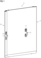
- a door device according to the invention of a sanitary cell of a rail vehicle is shown schematically in three dimensions. The figure shows the door device as seen from an interior of the sanitary cell.
- the door device is designed as a sliding door device and includes a movable door leaf 5, also called a door leaf.
- a first door lever 1 and a first locking element 3 are arranged in the area of a main closing edge 6 of the door leaf 5.
- the first door lever 1 is used to open and close the door device from the interior of the sanitary cell. It is designed accordingly to move the door leaf 5 along a predetermined guide between an open and a closed position.
- the first locking element 3 arranged above the first door lever 1 in turn serves to lock and unlock the door device. It is designed accordingly to lock and unlock the door leaf 5 in the closed position.
- the locking elements 3 and 4 are designed as rotary locks.
- a second door lever 2 and a second locking element 4 are provided, which are also on the surface of the door leaf 5 facing the interior of the sanitary cell are arranged and connected to this, wherein the second door lever 2 is coupled to the first door lever 1, so that an actuation of the second door lever 2 causes an actuation of the first door lever 1 and wherein the second locking element 4 is coupled to the first locking element 3, so that an actuation of the second locking element 4 causes an actuation of the first locking element 3, as in Fig. 2 and 3 is explained in more detail.
- the second door lever 2 is therefore also suitable for manually moving the door leaf 5 between an open and a closed position and the second locking element 4 is suitable for locking and unlocking the door device.
- Both the first and second door levers 1 and 2 as well as the first and second locking elements 3 and 4 can be operated manually and are freely accessible from the interior of the sanitary cell for a user of the sanitary cell.
- a second door lever is only arranged on the side of the door leaf facing the interior of the sanitary cell.
- the same also applies to a second locking element.
- a locking indicator can be assigned to the first locking element 3 on the outside and an interface for actuating the first locking element 3 with a predetermined tool from the outside. Free actuation of the first locking element 3 from the outside is not desirable for passengers.
- the first door lever 1 usually has a counterpart on the outside of the door leaf 5 facing away from the interior of the sanitary cell, in particular in the same place and identically constructed, so that the door leaf 5 can also be moved from the outside.
- the couplings of the control elements are integrated into the door leaf and hidden from the user.
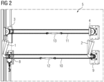
- Fig. 2 now shows the door leaf 5 with the cover of the couplings of the first and second door levers 1 and 2 and the first and second locking elements 3 and 4 open.
- Each door lever 1 and 2 and each locking element 3 and 4 each has a pinion - here only the gears 8 and 9 of the first and second door levers 1 and 2 are sketched - around which a chain 10 and 11 are stretched around the controls to couple with each other. In the middle of the chains 10 and 11, respective tendons 12 and 13 are provided.
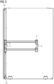
- Fig. 3 illustrates the functionality of the additional door lever 2 for moving the door, including, if necessary, simultaneously releasing a door brake 14, and the additional locking element 4 for locking/unlocking the door.
- the actual locking/unlocking and releasing of the door brake 14 takes place directly via the first door lever 1 or the first locking element 3.
- the first door lever 1 is directly connected to a braking mechanism of the door brake 14, the second door lever 2 indirectly via the coupling - here the mechanical transmission.
- the first locking element 3 is connected directly to a locking mechanism 15, the second door lever 2 only indirectly via the coupling.
- the original braking and locking mechanism of a manual door with only one door lever or locking element can be largely retained and is supplemented by the second door lever or locking element and their couplings.
- a door lever for moving the door while simultaneously releasing the door brake and a rotary latch for locking/unlocking the door are common. Operating the door from a wheelchair can be difficult or impossible due to the large opening width and/or long travel distance of a sliding door and only one door lever.
- the ability to operate the large manual door is significantly improved in the sense of the invention by a second, additional door lever for moving the door and an additional locking element for locking/unlocking the door.
- the respective control elements of a type are linked to one another and function synchronously.
Landscapes
- Lock And Its Accessories (AREA)
Claims (10)
- Dispositif de porte d'un bloc sanitaire d'un véhicule ferroviaire du transport des passagers comprenant un ventail (5) de porte mobile et un premier levier (1) de porte relié au ventail (5) de porte pour le déplacement manuel du ventail (5) de porte,
dans lequel le dispositif de porte a pour le déplacement manuel du ventail (5) de porte un autre deuxième levier (2) de porte, qui est accouplé au premier levier (1) de porte de manière à ce qu'un actionnement du deuxième levier (2) de porte provoque un actionnement du premier levier (1) de porte, dans lequel le dispositif de porte a pour le verrouillage et le déverrouillage du dispositif de porte un premier élément (3) de verrouillage relié au ventail (5) de porte et pouvant être actionné manuellement et un autre deuxième élément (4) de verrouillage relié au ventail (5) de porte et pouvant être actionné manuellement, dans lequel le premier élément (3) de verrouillage et le deuxième élément (4) de verrouillage sont accouplés l'un à l'autre de manière à ce que l'actionnement du deuxième élément (4) de verrouillage provoque un actionnement du premier élément (3) de verrouillage, dans lequel le premier levier (1) de porte est disposé dans la partie d'un bord (6) de fermeture principal du ventail (5) de porte, dans lequel le deuxième levier (2) de porte est disposé plus loin dans la direction d'un bord (7) de fermeture auxiliaire, opposé au bord (6) de fermeture principal, du ventail (5) de porte, et dans lequel le premier élément (3) de verrouillage est disposé dans la partie d'un bord (6) de fermeture principale du ventail (5) de porte, dans lequel le deuxième élément (4) de verrouillage est disposé plus loin dans la direction d'un bord (7) de fermeture auxiliaire, opposé au bord (6) de fermeture principal, du ventail (5) de porte. - Dispositif de porte suivant la revendication 1, caractérisé en ce que le premier levier (1) de porte et le deuxième levier (2) de porte sont accouplés mécaniquement par un mécanisme.
- Dispositif de porte suivant l'une des revendications 1 ou 2,
caractérisé en ce que le premier levier (1) de porte est constitué pour desserrer un frein (14) de porte et est accouplé au frein (14) de porte de manière à ce que l'actionnement du premier levier (1) de porte provoque pour le déplacement manuel du ventail (5) de porte un desserrage du frein (14) de porte. - Dispositif de porte suivant l'une des revendications 1 à 3, caractérisé en ce que le premier levier (1) de porte et le deuxième levier (2) de porte sont constitués pareillement.
- Dispositif de porte suivant l'une des revendications 1 à 4, caractérisé en ce que le premier élément (3) de verrouillage est constitué sous la forme d'un verrou à rotation ou à coulissement.
- Dispositif de porte suivant l'une des revendications 1 à 5, caractérisé en ce que le premier élément (3) de verrouillage et le deuxième élément (4) de verrouillage sont constitués pareillement.
- Dispositif de porte suivant l'une des revendications 1 à 6, caractérisé en ce que le premier élément (3) de verrouillage et le deuxième élément (4) de verrouillage sont accouplés mécaniquement par un mécanisme.
- Dispositif de porte suivant l'une des revendications 1 à 7, caractérisé en ce que l'accouplement du premier levier (1) de porte et du deuxième levier (2) de porte est monté dans le ventail (5) de porte et/ou en ce que l'accouplement du premier élément (3) de verrouillage et du deuxième élément (4) de verrouillage est monté dans le ventail (5) de porte.
- Véhicule ferroviaire comprenant au moins un dispositif de porte suivant l'une des revendications 1 à 8.
- Véhicule ferroviaire suivant la revendication 9, caractérisé en ce que le ventail (5) de porte est prévu pour séparer un espace intérieur d'un bloc sanitaire d'un autre véhicule ferroviaire, dans lequel le deuxième levier (2) de porte est disposé exclusivement du côté du ventail (5) de porte tourné, dans une position fermée du ventail (5) de porte, vers l'intérieur du bloc sanitaire.
Applications Claiming Priority (2)
| Application Number | Priority Date | Filing Date | Title |
|---|---|---|---|
| DE102019218585.1A DE102019218585A1 (de) | 2019-11-29 | 2019-11-29 | Tür mit zusätzlichen Türbedienelementen |
| PCT/EP2020/080575 WO2021104796A1 (fr) | 2019-11-29 | 2020-10-30 | Porte dotée d'éléments de commande de porte supplémentaires |
Publications (3)
| Publication Number | Publication Date |
|---|---|
| EP4065799A1 EP4065799A1 (fr) | 2022-10-05 |
| EP4065799C0 EP4065799C0 (fr) | 2023-11-29 |
| EP4065799B1 true EP4065799B1 (fr) | 2023-11-29 |
Family
ID=73344003
Family Applications (1)
| Application Number | Title | Priority Date | Filing Date |
|---|---|---|---|
| EP20804461.0A Active EP4065799B1 (fr) | 2019-11-29 | 2020-10-30 | Porte dotée d'éléments de commande de porte supplémentaires |
Country Status (4)
| Country | Link |
|---|---|
| EP (1) | EP4065799B1 (fr) |
| DE (1) | DE102019218585A1 (fr) |
| ES (1) | ES2971341T3 (fr) |
| WO (1) | WO2021104796A1 (fr) |
Family Cites Families (4)
| Publication number | Priority date | Publication date | Assignee | Title |
|---|---|---|---|---|
| US7013687B2 (en) * | 2002-04-30 | 2006-03-21 | Haworth, Ltd. | Sliding door lock with single lock-release and door-opening motion |
| FR2866667A1 (fr) * | 2004-02-23 | 2005-08-26 | Der Mye David Harry Van | Dispositif qui selon les cas, permet de rehausser ou d'abaisser une poignee de porte |
| US8448997B2 (en) * | 2010-01-21 | 2013-05-28 | Stanley Black & Decker, Inc. | Sliding door lock with dual break-out release |
| DE102012108157B3 (de) * | 2012-09-03 | 2014-05-22 | Bombardier Transportation Gmbh | Schienenfahrzeug mit einer Schiebetür und Schienenfahrzeugwagen mit einer WC-Einheit |
-
2019
- 2019-11-29 DE DE102019218585.1A patent/DE102019218585A1/de not_active Ceased
-
2020
- 2020-10-30 ES ES20804461T patent/ES2971341T3/es active Active
- 2020-10-30 WO PCT/EP2020/080575 patent/WO2021104796A1/fr not_active Ceased
- 2020-10-30 EP EP20804461.0A patent/EP4065799B1/fr active Active
Also Published As
| Publication number | Publication date |
|---|---|
| EP4065799C0 (fr) | 2023-11-29 |
| EP4065799A1 (fr) | 2022-10-05 |
| DE102019218585A1 (de) | 2021-06-02 |
| ES2971341T3 (es) | 2024-06-04 |
| WO2021104796A1 (fr) | 2021-06-03 |
Similar Documents
| Publication | Publication Date | Title |
|---|---|---|
| DE102009044832B4 (de) | Schloss für eine Gepäckbox | |
| DE102004045988B3 (de) | Anzeige zur Signalisierung der Nichtverriegelung einer klappbaren Rückenlehne eines Kraftfahrzeugsitzes | |
| EP1516847B1 (fr) | Dispositif pour accoupler porte cabine et porte palière et dispositif pour déverrouiller la porte cabine en cas de secours | |
| EP2855807B1 (fr) | Dispositif de serrure de porte pour une porte anti-panique | |
| DE19653220A1 (de) | Sicherbare Verriegelungsvorrichtung für ein bewegliches Element eines Kraftfahrzeugsitzes | |
| DE60205996T2 (de) | Öffnungsschliesseinrichtung | |
| DE102015214086B4 (de) | Türsystem für einen wenigstens zwei Sitzreihen umfassenden Personenkraftwagen | |
| DE10023311A1 (de) | Kraftfahrzeug-Türschließsystem mit Schnellentriegelung | |
| DE10000639B4 (de) | Betätigungsvorrichtung für Schiebetür | |
| DE102013000285A1 (de) | Türschlossvorrichtung für eine Paniktür | |
| DE102013000286A1 (de) | Türschlossvorrichtung für eine Tür mit mindestens einem Türflügel | |
| EP4065799B1 (fr) | Porte dotée d'éléments de commande de porte supplémentaires | |
| DE202006005103U1 (de) | Verstellsystem für einen Fahrzeugsitz | |
| DE102008021979A1 (de) | Betätigungseinrichtung zur Entriegelung von Fahrzeugtüren | |
| WO2024041699A1 (fr) | Serrure de véhicule automobile | |
| EP4547591A1 (fr) | Ascenseur | |
| DE4221493C2 (de) | Kombinierter Entriegelungs- und Sicherungsmechanismus für eine an der Stirnseite eines Nahverkehrs-Schienenfahrzeuges angeordnete Notausstiegstür | |
| DE102018121363B3 (de) | Passagiertüranordnung für ein Flugzeugsegment | |
| CH713012B1 (de) | Türdrücker. | |
| DE3017731C2 (de) | Kraftfahrzeugtürverschluß | |
| DE202021002578U1 (de) | Verriegelungsvorrichtung für Schwenkschiebetüren von Fahzeugen | |
| DE60211819T2 (de) | Vorrichtung zum Öffnen und Schliessen einer Dreh-Schiebetür für Kraftfahrzeuge | |
| EP3798393A1 (fr) | Dispositif de commande d'urgence destiné à l'ouverture manuelle d'une porte de véhicule | |
| DE3244705A1 (de) | Schliess- und verriegelungseinrichtung | |
| EP4650557A1 (fr) | Ensemble poignée de porte |
Legal Events
| Date | Code | Title | Description |
|---|---|---|---|
| STAA | Information on the status of an ep patent application or granted ep patent |
Free format text: STATUS: UNKNOWN |
|
| STAA | Information on the status of an ep patent application or granted ep patent |
Free format text: STATUS: THE INTERNATIONAL PUBLICATION HAS BEEN MADE |
|
| PUAI | Public reference made under article 153(3) epc to a published international application that has entered the european phase |
Free format text: ORIGINAL CODE: 0009012 |
|
| STAA | Information on the status of an ep patent application or granted ep patent |
Free format text: STATUS: REQUEST FOR EXAMINATION WAS MADE |
|
| 17P | Request for examination filed |
Effective date: 20220427 |
|
| AK | Designated contracting states |
Kind code of ref document: A1 Designated state(s): AL AT BE BG CH CY CZ DE DK EE ES FI FR GB GR HR HU IE IS IT LI LT LU LV MC MK MT NL NO PL PT RO RS SE SI SK SM TR |
|
| DAV | Request for validation of the european patent (deleted) | ||
| DAX | Request for extension of the european patent (deleted) | ||
| GRAP | Despatch of communication of intention to grant a patent |
Free format text: ORIGINAL CODE: EPIDOSNIGR1 |
|
| STAA | Information on the status of an ep patent application or granted ep patent |
Free format text: STATUS: GRANT OF PATENT IS INTENDED |
|
| INTG | Intention to grant announced |
Effective date: 20230714 |
|
| GRAS | Grant fee paid |
Free format text: ORIGINAL CODE: EPIDOSNIGR3 |
|
| GRAA | (expected) grant |
Free format text: ORIGINAL CODE: 0009210 |
|
| STAA | Information on the status of an ep patent application or granted ep patent |
Free format text: STATUS: THE PATENT HAS BEEN GRANTED |
|
| AK | Designated contracting states |
Kind code of ref document: B1 Designated state(s): AL AT BE BG CH CY CZ DE DK EE ES FI FR GB GR HR HU IE IS IT LI LT LU LV MC MK MT NL NO PL PT RO RS SE SI SK SM TR |
|
| REG | Reference to a national code |
Ref country code: GB Ref legal event code: FG4D Free format text: NOT ENGLISH |
|
| REG | Reference to a national code |
Ref country code: CH Ref legal event code: EP |
|
| REG | Reference to a national code |
Ref country code: DE Ref legal event code: R096 Ref document number: 502020006235 Country of ref document: DE |
|
| REG | Reference to a national code |
Ref country code: IE Ref legal event code: FG4D Free format text: LANGUAGE OF EP DOCUMENT: GERMAN |
|
| U01 | Request for unitary effect filed |
Effective date: 20231206 |
|
| U07 | Unitary effect registered |
Designated state(s): AT BE BG DE DK EE FI FR IT LT LU LV MT NL PT SE SI Effective date: 20231212 |
|
| PG25 | Lapsed in a contracting state [announced via postgrant information from national office to epo] |
Ref country code: GR Free format text: LAPSE BECAUSE OF FAILURE TO SUBMIT A TRANSLATION OF THE DESCRIPTION OR TO PAY THE FEE WITHIN THE PRESCRIBED TIME-LIMIT Effective date: 20240301 |
|
| PG25 | Lapsed in a contracting state [announced via postgrant information from national office to epo] |
Ref country code: IS Free format text: LAPSE BECAUSE OF FAILURE TO SUBMIT A TRANSLATION OF THE DESCRIPTION OR TO PAY THE FEE WITHIN THE PRESCRIBED TIME-LIMIT Effective date: 20240329 |
|
| PG25 | Lapsed in a contracting state [announced via postgrant information from national office to epo] |
Ref country code: IS Free format text: LAPSE BECAUSE OF FAILURE TO SUBMIT A TRANSLATION OF THE DESCRIPTION OR TO PAY THE FEE WITHIN THE PRESCRIBED TIME-LIMIT Effective date: 20240329 Ref country code: GR Free format text: LAPSE BECAUSE OF FAILURE TO SUBMIT A TRANSLATION OF THE DESCRIPTION OR TO PAY THE FEE WITHIN THE PRESCRIBED TIME-LIMIT Effective date: 20240301 |
|
| PG25 | Lapsed in a contracting state [announced via postgrant information from national office to epo] |
Ref country code: RS Free format text: LAPSE BECAUSE OF FAILURE TO SUBMIT A TRANSLATION OF THE DESCRIPTION OR TO PAY THE FEE WITHIN THE PRESCRIBED TIME-LIMIT Effective date: 20231129 Ref country code: PL Free format text: LAPSE BECAUSE OF FAILURE TO SUBMIT A TRANSLATION OF THE DESCRIPTION OR TO PAY THE FEE WITHIN THE PRESCRIBED TIME-LIMIT Effective date: 20231129 Ref country code: NO Free format text: LAPSE BECAUSE OF FAILURE TO SUBMIT A TRANSLATION OF THE DESCRIPTION OR TO PAY THE FEE WITHIN THE PRESCRIBED TIME-LIMIT Effective date: 20240229 Ref country code: HR Free format text: LAPSE BECAUSE OF FAILURE TO SUBMIT A TRANSLATION OF THE DESCRIPTION OR TO PAY THE FEE WITHIN THE PRESCRIBED TIME-LIMIT Effective date: 20231129 |
|
| REG | Reference to a national code |
Ref country code: ES Ref legal event code: FG2A Ref document number: 2971341 Country of ref document: ES Kind code of ref document: T3 Effective date: 20240604 |
|
| PG25 | Lapsed in a contracting state [announced via postgrant information from national office to epo] |
Ref country code: CZ Free format text: LAPSE BECAUSE OF FAILURE TO SUBMIT A TRANSLATION OF THE DESCRIPTION OR TO PAY THE FEE WITHIN THE PRESCRIBED TIME-LIMIT Effective date: 20231129 |
|
| PG25 | Lapsed in a contracting state [announced via postgrant information from national office to epo] |
Ref country code: SK Free format text: LAPSE BECAUSE OF FAILURE TO SUBMIT A TRANSLATION OF THE DESCRIPTION OR TO PAY THE FEE WITHIN THE PRESCRIBED TIME-LIMIT Effective date: 20231129 |
|
| PG25 | Lapsed in a contracting state [announced via postgrant information from national office to epo] |
Ref country code: SM Free format text: LAPSE BECAUSE OF FAILURE TO SUBMIT A TRANSLATION OF THE DESCRIPTION OR TO PAY THE FEE WITHIN THE PRESCRIBED TIME-LIMIT Effective date: 20231129 Ref country code: SK Free format text: LAPSE BECAUSE OF FAILURE TO SUBMIT A TRANSLATION OF THE DESCRIPTION OR TO PAY THE FEE WITHIN THE PRESCRIBED TIME-LIMIT Effective date: 20231129 Ref country code: RO Free format text: LAPSE BECAUSE OF FAILURE TO SUBMIT A TRANSLATION OF THE DESCRIPTION OR TO PAY THE FEE WITHIN THE PRESCRIBED TIME-LIMIT Effective date: 20231129 Ref country code: CZ Free format text: LAPSE BECAUSE OF FAILURE TO SUBMIT A TRANSLATION OF THE DESCRIPTION OR TO PAY THE FEE WITHIN THE PRESCRIBED TIME-LIMIT Effective date: 20231129 |
|
| REG | Reference to a national code |
Ref country code: DE Ref legal event code: R097 Ref document number: 502020006235 Country of ref document: DE |
|
| PLBE | No opposition filed within time limit |
Free format text: ORIGINAL CODE: 0009261 |
|
| STAA | Information on the status of an ep patent application or granted ep patent |
Free format text: STATUS: NO OPPOSITION FILED WITHIN TIME LIMIT |
|
| 26N | No opposition filed |
Effective date: 20240830 |
|
| U20 | Renewal fee for the european patent with unitary effect paid |
Year of fee payment: 5 Effective date: 20241018 |
|
| PGFP | Annual fee paid to national office [announced via postgrant information from national office to epo] |
Ref country code: ES Payment date: 20250121 Year of fee payment: 5 |
|
| REG | Reference to a national code |
Ref country code: CH Ref legal event code: PL |
|
| PG25 | Lapsed in a contracting state [announced via postgrant information from national office to epo] |
Ref country code: MC Free format text: LAPSE BECAUSE OF FAILURE TO SUBMIT A TRANSLATION OF THE DESCRIPTION OR TO PAY THE FEE WITHIN THE PRESCRIBED TIME-LIMIT Effective date: 20231129 |
|
| PG25 | Lapsed in a contracting state [announced via postgrant information from national office to epo] |
Ref country code: CH Free format text: LAPSE BECAUSE OF NON-PAYMENT OF DUE FEES Effective date: 20241031 |
|
| PG25 | Lapsed in a contracting state [announced via postgrant information from national office to epo] |
Ref country code: IE Free format text: LAPSE BECAUSE OF NON-PAYMENT OF DUE FEES Effective date: 20241030 |
|
| U20 | Renewal fee for the european patent with unitary effect paid |
Year of fee payment: 6 Effective date: 20251020 |
|
| U1H | Name or address of the proprietor changed after the registration of the unitary effect |
Owner name: SIEMENS MOBILITY GMBH; DE |
|
| PGFP | Annual fee paid to national office [announced via postgrant information from national office to epo] |
Ref country code: GB Payment date: 20251111 Year of fee payment: 6 |
|
| PG25 | Lapsed in a contracting state [announced via postgrant information from national office to epo] |
Ref country code: HU Free format text: LAPSE BECAUSE OF FAILURE TO SUBMIT A TRANSLATION OF THE DESCRIPTION OR TO PAY THE FEE WITHIN THE PRESCRIBED TIME-LIMIT; INVALID AB INITIO Effective date: 20201030 |