EP4065799B1 - Tür mit zusätzlichen türbedienelementen - Google Patents
Tür mit zusätzlichen türbedienelementen Download PDFInfo
- Publication number
- EP4065799B1 EP4065799B1 EP20804461.0A EP20804461A EP4065799B1 EP 4065799 B1 EP4065799 B1 EP 4065799B1 EP 20804461 A EP20804461 A EP 20804461A EP 4065799 B1 EP4065799 B1 EP 4065799B1
- Authority
- EP
- European Patent Office
- Prior art keywords
- door
- lever
- locking element
- leaf
- door leaf
- Prior art date
- Legal status (The legal status is an assumption and is not a legal conclusion. Google has not performed a legal analysis and makes no representation as to the accuracy of the status listed.)
- Active
Links
Images
Classifications
-
- E—FIXED CONSTRUCTIONS
- E05—LOCKS; KEYS; WINDOW OR DOOR FITTINGS; SAFES
- E05B—LOCKS; ACCESSORIES THEREFOR; HANDCUFFS
- E05B1/00—Knobs or handles for wings; Knobs, handles, or press buttons for locks or latches on wings
- E05B1/0053—Handles or handle attachments facilitating operation, e.g. by children or burdened persons
-
- E—FIXED CONSTRUCTIONS
- E05—LOCKS; KEYS; WINDOW OR DOOR FITTINGS; SAFES
- E05B—LOCKS; ACCESSORIES THEREFOR; HANDCUFFS
- E05B53/00—Operation or control of locks by mechanical transmissions, e.g. from a distance
Definitions
- the invention relates to a door device for a sanitary cell of a passenger rail vehicle with a movable door leaf and a first door lever connected to the door leaf for manually moving the door leaf.
- Universal wet rooms in rail vehicles can be designed for the special needs of wheelchair users. It should be ensured that all facilities in the wet room can be operated by the person sitting in the wheelchair. This includes, for example, the independent opening and closing as well as the locking and unlocking of the wet room door. For automatic doors, this can be achieved using one or more push buttons in accessible locations.
- Printed publication DE 10 2012 108157 B3 relates to a sliding door device of a sanitary cell of a passenger rail vehicle with a braking device.
- US 2011/173891 A1 reveals a sliding door with two door handles offset from one another at one height. These are each coupled with a locking mechanism.
- FR 2 866 667 A1 teaches two door handles that are vertically offset from each other. One door handle is located at a height for adult operation and another door handle is located slightly lower to facilitate child operation.
- the invention is based on the object of improving the operation of manual doors.
- the door device then has a further, second door lever for manually moving the door leaf, which is coupled to the first door lever, so that an actuation of the second door lever causes an actuation of the first door lever.
- the door device can in particular be designed as a sliding door.
- the door leaf is moved, in particular displaced, between an open and a closed position, in particular by means of the first and/or the second door lever.
- the first door lever and/or the second door lever are advantageously arranged on the door leaf.
- the door leaf can also be referred to as a door leaf.
- the first door lever is designed to be suitable for manually operating the door device and thus for moving the door leaf, in particular between the open and closed positions.
- the first door lever is therefore suitable for opening and closing the door device manually using the first door lever.
- first door lever and the second door lever are designed identically.
- first door lever and the second door lever are coupled to one another in such a way that a manual movement of the second door lever via the coupling leads to an identical movement of the first door lever, which in turn results in a manually executed, identical movement of the first door lever.
- the first door lever and the second door lever are mechanically coupled via a transmission, for example via a gear transmission, a linkage or via a chain drive.
- the first door lever can be rotated about a first point at a predetermined angle.
- the second door lever is also mounted rotatably about a second point at the predetermined angle.
- Gear wheels are arranged in the respective area of their pivot points, which in turn are connected to one another with a tensioned chain. A manual movement of the second door lever about the second pivot point leads to an identical rotational movement of the first door lever about the first pivot point via the coupling.
- the first door lever is coupled to a door brake and is designed to be suitable so that the actuation of the first door lever for manually moving the door leaf causes the door brake to be released.
- the second door lever is now coupled to the first door lever in such a way that an actuation of the second door lever causes an actuation of the first door lever, the actuation of the second door lever for manually moving the door leaf also causes the door brake to be released.
- the movement of the first door lever can be specified by at least 25° around the first pivot point.
- the movement of the second door lever can be specified by at least 25° around the second pivot point.
- the first and/or the second door lever can be placed or held in a non-deflected neutral position in a state free from external forces via a restoring element, for example a spring.
- the door device can have a correspondingly suitably designed reset element.
- a specified force must be applied. After manual operation of one of the door levers, they are returned to the neutral position as soon as the external force, in particular manually applied, no longer acts on them to the predetermined extent.
- the door brake can be designed in such a way and coupled directly to the first door lever and indirectly to the second door lever via their coupling so that it is locked in the neutral position. Releasing one of the door levers automatically resets the door levers and locks the door brake.
- one of the door levers is manually moved out of the neutral position in the direction of the desired movement, whereby a force is transferred from the door lever to the door leaf and is applied in the direction of the desired movement and the door leaf brake released, moved becomes.
- one of the door levers is also manually moved out of the neutral position in the direction of the desired movement, whereby a force is transmitted from the door lever to the door leaf and applied in the direction of the desired movement and the door leaf is moved when the brake is released.
- the door device has a manually operable first locking element connected to the door leaf for locking and unlocking the door device and a further second locking element connected to the door leaf and manually operable, the first locking element and the second locking element being coupled to one another , so that actuation of the second locking element causes actuation of the first locking element.
- the actuation of the second locking element via the coupling leads to an actuation of the first locking element and thus to a locking and/or unlocking of the door device.
- the first and second locking elements can be designed identically and/or coupled to one another in such a way that a manual movement of the second locking element via the coupling leads to an identical movement of the first locking element.
- the first and second locking elements are also further developed mechanically coupled via a gear, for example via a gear transmission, a linkage or via a chain drive.
- first locking element and/or the second locking element are designed as a rotary or sliding lock. They are arranged on the door leaf, in particular freely accessible.
- the movement of the first and/or the second locking element can be at least 90 ° can be specified around another pivot point in order to lock and / or unlock the door device.
- first door lever and/or the second door lever as well as the first locking element and/or the second locking element are advantageously arranged in a freely accessible manner on the door leaf.
- the coupling of the first door lever and the second door lever is further developed and arranged in the door leaf.
- the coupling of the first locking element and the second locking element can also be arranged in the door leaf. The coupling or couplings are therefore concealed in the door leaf and protected from vandalism.
- the first door lever is arranged in the area of a main closing edge of the door leaf, with the second door lever being arranged further in the direction of a secondary closing edge of the door leaf opposite the main closing edge.
- the first locking element is also arranged in the area of the main closing edge of the door leaf, with the second locking element being arranged further in the direction of a secondary closing edge of the door leaf opposite the main closing edge.
- the first and second door levers are arranged at the same first height.
- the first and second locking elements can also advantageously be arranged at the same second height.
- the first and second heights may differ.
- the door lever and locking elements then each lie in a horizontal plane, with the horizontal plane of the door lever and the horizontal plane of the locking elements having a distance greater than zero in the vertical direction from one another.
- both the door levers and, if applicable, the locking elements are offset from one another - the first and the second door levers have a distance greater than zero in the horizontal direction from one another and the first and the second locking elements also have a distance greater than zero from one another in the horizontal direction exhibit.
- the door levers and the locking elements are in a common plane. Their distances in the horizontal direction are the same.
- the main closing edge of the door leaf is the closing edge, the distance of which from the parallel counter-closing edge of a door frame determines the opening width of the door device.
- the secondary closing edge of the door leaf is opposite the main closing edge and in particular runs parallel to it.
- the first door lever is arranged, for example, in the area of the main closing edge of the door leaf at a predetermined first height above the floor.
- the first locking element is also arranged in the area of the main closing edge of the door leaf at a predetermined second height above the floor, for example slightly below the first door lever.
- the first door lever and the first locking element lie, for example, on a vertical line.
- the first height is slightly larger than the second height.
- the second door lever is arranged, for example, in a central area of the door leaf between the main closing edge and the secondary closing edge opposite the main closing edge or even in an area between the center of the door leaf and the secondary closing edge of the door leaf opposite the main closing edge at the predetermined first height above the floor.
- the second locking element can in turn be arranged in a vertical line with the second door lever at the second height on the door leaf.
- first locking element can be integrated into the first door lever.
- first locking element and the first door lever form an integral component.
- second locking element and the second door lever can form an integral component.
- the first and second door levers as well as the first locking element and the second locking element can each be designed identically.
- the door device is designed to be suitable for use in a passenger rail vehicle, in particular for separating the interior of a sanitary cell of the rail vehicle from the further interior of the rail vehicle.
- a rail vehicle according to the invention thus comprises at least one door device according to the invention, in particular a sanitary cell of the rail vehicle comprises the door device in order to separate an interior of the sanitary cell from the further interior of the rail vehicle.
- the second door lever and possibly also the second locking element are arranged exclusively on the side of the door leaf facing the interior of the sanitary cell when the door leaf is in a closed position.
- the sanitary cell is designed to be handicapped accessible, particularly suitable for wheelchair users.
- Such sanitary cells can also be referred to as universal wet cells.
- An advantage of the invention is the significantly improved accessibility of the control units for wheelchair users and the resulting improved ability to operate the door. Intuitive operation is possible by using familiar operating levers and rotary locks.
- the two coupled control units for moving the sliding door, possibly including releasing the door brake unit, and for locking/unlocking the door can be integrated in a space-saving manner, in particular mechanically coupled, in a door leaf.
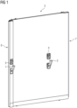
- a door device according to the invention of a sanitary cell of a rail vehicle is shown schematically in three dimensions. The figure shows the door device as seen from an interior of the sanitary cell.
- the door device is designed as a sliding door device and includes a movable door leaf 5, also called a door leaf.
- a first door lever 1 and a first locking element 3 are arranged in the area of a main closing edge 6 of the door leaf 5.
- the first door lever 1 is used to open and close the door device from the interior of the sanitary cell. It is designed accordingly to move the door leaf 5 along a predetermined guide between an open and a closed position.
- the first locking element 3 arranged above the first door lever 1 in turn serves to lock and unlock the door device. It is designed accordingly to lock and unlock the door leaf 5 in the closed position.
- the locking elements 3 and 4 are designed as rotary locks.
- a second door lever 2 and a second locking element 4 are provided, which are also on the surface of the door leaf 5 facing the interior of the sanitary cell are arranged and connected to this, wherein the second door lever 2 is coupled to the first door lever 1, so that an actuation of the second door lever 2 causes an actuation of the first door lever 1 and wherein the second locking element 4 is coupled to the first locking element 3, so that an actuation of the second locking element 4 causes an actuation of the first locking element 3, as in Fig. 2 and 3 is explained in more detail.
- the second door lever 2 is therefore also suitable for manually moving the door leaf 5 between an open and a closed position and the second locking element 4 is suitable for locking and unlocking the door device.
- Both the first and second door levers 1 and 2 as well as the first and second locking elements 3 and 4 can be operated manually and are freely accessible from the interior of the sanitary cell for a user of the sanitary cell.
- a second door lever is only arranged on the side of the door leaf facing the interior of the sanitary cell.
- the same also applies to a second locking element.
- a locking indicator can be assigned to the first locking element 3 on the outside and an interface for actuating the first locking element 3 with a predetermined tool from the outside. Free actuation of the first locking element 3 from the outside is not desirable for passengers.
- the first door lever 1 usually has a counterpart on the outside of the door leaf 5 facing away from the interior of the sanitary cell, in particular in the same place and identically constructed, so that the door leaf 5 can also be moved from the outside.
- the couplings of the control elements are integrated into the door leaf and hidden from the user.
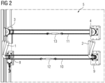
- Fig. 2 now shows the door leaf 5 with the cover of the couplings of the first and second door levers 1 and 2 and the first and second locking elements 3 and 4 open.
- Each door lever 1 and 2 and each locking element 3 and 4 each has a pinion - here only the gears 8 and 9 of the first and second door levers 1 and 2 are sketched - around which a chain 10 and 11 are stretched around the controls to couple with each other. In the middle of the chains 10 and 11, respective tendons 12 and 13 are provided.
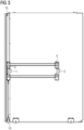
- Fig. 3 illustrates the functionality of the additional door lever 2 for moving the door, including, if necessary, simultaneously releasing a door brake 14, and the additional locking element 4 for locking/unlocking the door.
- the actual locking/unlocking and releasing of the door brake 14 takes place directly via the first door lever 1 or the first locking element 3.
- the first door lever 1 is directly connected to a braking mechanism of the door brake 14, the second door lever 2 indirectly via the coupling - here the mechanical transmission.
- the first locking element 3 is connected directly to a locking mechanism 15, the second door lever 2 only indirectly via the coupling.
- the original braking and locking mechanism of a manual door with only one door lever or locking element can be largely retained and is supplemented by the second door lever or locking element and their couplings.
- a door lever for moving the door while simultaneously releasing the door brake and a rotary latch for locking/unlocking the door are common. Operating the door from a wheelchair can be difficult or impossible due to the large opening width and/or long travel distance of a sliding door and only one door lever.
- the ability to operate the large manual door is significantly improved in the sense of the invention by a second, additional door lever for moving the door and an additional locking element for locking/unlocking the door.
- the respective control elements of a type are linked to one another and function synchronously.
Landscapes
- Lock And Its Accessories (AREA)
Description
- Die Erfindung betrifft eine Türvorrichtung für eine Sanitärzelle eines Schienenfahrzeugs des Personenverkehrs mit einem bewegbaren Türblatt und einem mit dem Türblatt verbundenen ersten Türhebel zum manuellen Bewegen des Türblatts.
- Universalnasszellen in Schienenfahrzeugen können für die besonderen Bedürfnisse von Rollstuhlfahrer ausgelegt sein. Die Bedienung aller Einrichtungen der Nasszelle durch die im Rollstuhl sitzende Person sollte gewährleitet sein. Dazu gehört beispielsweise das eigenständige Öffnen und Schließen sowie das Ver- und Entriegeln der Nasszellentür. Bei automatischen Türen kann dies durch einen oder mehrere Drucktaster an zugänglichen Stellen realisiert werden.
- Bei größeren, manuell zu verschiebenden Türen kann hingegen die Bedienung der Tür aus dem Rollstuhl heraus durch die gro-ße Öffnungsweite und/oder den großen Verfahrweg erschwert bis unmöglich sein.
- Druckschrift
DE 10 2012 108157 B3 betrifft eine Schiebetürvorrichtung einer Sanitärzelle eines Schienenfahrzeugs des Personenverkehrs mit einer Bremsvorrichtung. - Die Patentschrift
US 7 013 687 B2 offenbart eine Schiebetür mit einem Türgriff und einem Verriegelungselement, welche miteinander gekoppelt sind, so dass die Schiebetür in einer Bewegung durch Betätigung des Türgriffs zu entriegeln und zu öffnen ist. -
US 2011 /173891 A1 offenbart eine Schiebetür mit zwei zueinander versetzten Türgriffen auf einer Höhe. Diese sind jeweils mit einem Verriegelungsmechanismus gekoppelt. -
FR 2 866 667 A1 - Der Erfindung liegt die Aufgabe zugrunde, die Bedienung von manuellen Türen zu verbessern.
- Gelöst wird die Aufgabe durch den Gegenstand des unabhängigen Patentanspruchs 1. Weiterbildungen und Ausgestaltungen der Erfindung finden sich in den Merkmalen der abhängigen Patentansprüche wieder.
- Eine erfindungsgemäße Türvorrichtung für eine Sanitärzelle eines Schienenfahrzeugs des Personenverkehrs umfasst ein bewegbares, insbesondere verschiebbares, Türblatt und einen mit dem Türblatt verbundenen ersten Türhebel zum manuellen Bewegen des Türblatts. Fürderhin weist die Türvorrichtung einen weiteren, zweiten Türhebel zum manuellen Bewegen des Türblatts auf, welcher mit dem ersten Türhebel gekoppelt ist, so dass eine Betätigung des zweiten Türhebels eine Betätigung des ersten Türhebels bewirkt. Die Türvorrichtung kann dabei insbesondere als Schiebetür ausgebildet sein. Das Türblatt wird, insbesondere mittels des ersten und/oder des zweiten Türhebels, zwischen einer offenen und einer geschlossenen Stellung bewegt, insbesondere verschoben. Der erste Türhebel und/oder der zweite Türhebel sind vorteilhaft auf dem Türblatt angeordnet. Das Türblatt kann auch als Türflügel bezeichnet werden.
- Der erste Türhebel ist geeignet ausgebildet zum manuellen Betätigen der Türvorrichtung und somit zum Bewegen des Türblatts, insbesondere zwischen der offenen und der geschlossenen Stellung. Somit ist der erste Türhebel geeignet, die Türvorrichtung manuell mittels des ersten Türhebels zu öffnen und zu schließen.
- Weitergebildet sind der erste Türhebel und der zweite Türhebel identisch ausgebildet.
- Insbesondere sind der erste Türhebel und der zweite Türhebel derart miteinander gekoppelt, dass eine manuelle Bewegung des zweiten Türhebels über die Kopplung zu einer identischen Bewegung des ersten Türhebels führt, welche wiederum gleich zu einer manuell ausgeführten, identischen Bewegung des ersten Türhebels wirkt.
- Der erste Türhebel und der zweite Türhebel sind weitergebildet mechanisch über ein Getriebe gekoppelt, beispielsweise über ein Zahnradgetriebe, ein Gestänge oder über einen Kettentrieb.
- Beispielsweise ist der erste Türhebel um einen ersten Punkt in einem vorgegebenen Winkel drehbar. Dann ist auch der zweite Türhebel um einen zweiten Punkt in dem vorgegebenen Winkel drehbar gelagert. Im jeweiligen Bereich ihrer Drehpunkte sind Zahnräder angeordnet, welche ihrerseits mit einer gespannten Kette miteinander verbunden sind. Eine manuelle Bewegung des zweiten Türhebels um den zweiten Drehpunkt führt über die Kopplung zu einer identischen Drehbewegung des ersten Türhebels um den ersten Drehpunkt.
- Alternativ ist ein teilweiser oder kompletter Ersatz der Kette zum Beispiel durch einen Bowdenzug möglich, was insbesondere zu einer Gewichtsersparnis führt. Anstelle Kette und Zahnräder sind auch entsprechende einseitige Hebelmechanismen denkbar, bei denen die einzelnen Türhebel durch Gestänge miteinander verbunden sind.
- Gemäß einer weiteren Weiterbildung ist der erste Türhebel mit einer Türbremse gekoppelt und geeignet ausgebildet, dass die Betätigung des ersten Türhebels zum manuellen Bewegen des Türblatts ein Lösen der Türbremse bewirkt.
- Da nun der zweite Türhebel mit dem ersten Türhebel derart gekoppelt ist, dass eine Betätigung des zweiten Türhebels eine Betätigung des ersten Türhebels bewirkt, wird auch durch die Betätigung des zweiten Türhebels zum manuellen Bewegen des Türblatts ein Lösen der Türbremse bewirkt.
- Zum Lösen der Türbremse kann die Bewegung des ersten Türhebels um wenigstens 25° um den ersten Drehpunkt vorgegeben werden. Um nun die Türbremse über die manuelle Betätigung des zweiten Türhebels zu steuern, kann die Bewegung des zweiten Türhebels um wenigstens 25° um den zweiten Drehpunkt vorgegeben werden.
- Der erste und/oder der zweite Türhebel können in einem von äußeren Kräften freien Zustand über ein Rückstellungselement, beispielsweise eine Feder, in eine nicht ausgelenkte Neutralstellung gestellt bzw. gehalten werden. Die Türvorrichtung kann ein entsprechend geeignet ausgebildetes Rückstellungselement aufweisen. Zur manuellen Betätigung eines der Türhebel muss eine vorgegebene Kraft aufgebracht werden. Nach manueller Betätigung eines der Türhebel werden diese wiederum in die Neutralstellung zurückgestellt, sobald die, insbesondere manuell aufgebrachte, äußere Kraft nicht mehr in vorgegebenem Maße auf sie einwirkt.
- Die Türbremse kann derart ausgebildet und mit dem ersten Türhebel unmittelbar und mit dem zweiten Türhebel über deren Kopplung mittelbar gekoppelt sein, dass sie in Neutralstellung festgestellt ist. Das Loslassen eines der Türhebel führt automatisch zur Rückstellung der Türhebel und zum Feststellen der Türbremse.
- Zum Bewegen, insbesondere Verschieben, des Türblatts in die geöffnete Stellung wird einer der Türhebel aus der Neutralstellung manuell heraus in Richtung der gewünschten Bewegung bewegt, wodurch eine Kraft vom Türhebel auf das Türblatt übertragen und in Richtung der gewünschten Bewegung aufgebracht wird und das Türblatt, bei gelöster Bremse, verschoben wird. Zum Bewegen des Türblatts aus einer (teil-)geöffneten Stellung in die geschlossene Stellung wird gleichermaßen einer der Türhebel aus der Neutralstellung manuell heraus in Richtung der gewünschten Bewegung bewegt, wodurch eine Kraft vom Türhebel auf das Türblatt übertragen und in Richtung der gewünschten Bewegung aufgebracht wird und das Türblatt, bei gelöster Bremse, verschoben wird.
- Darüber hinaus weist die Türvorrichtung erfindungsgemäß ein mit dem Türblatt verbundenes, manuell betätigbares erstes Verriegelungselement zum Ver- und Entriegeln der Türvorrichtung und ein weiteres, mit dem Türblatt verbundenes und manuell betätigbares, zweites Verriegelungselement auf, wobei das erste Verriegelungselement und das zweite Verriegelungselement miteinander gekoppelt sind, so dass die Betätigung des zweiten Verriegelungselements eine Betätigung des ersten Verriegelungselements bewirkt.
- Analog zu den Türhebeln führt die Betätigung des zweiten Verriegelungselements über die Kopplung zu einer Betätigung des ersten Verriegelungselements und somit zu einem Ver- und/oder Entriegeln der Türvorrichtung. Gleichermaßen können das erste und das zweite Verriegelungselement identisch ausgebildet und/oder derart miteinander gekoppelt sein, dass eine manuelle Bewegung des zweiten Verriegelungselements über die Kopplung zu einer identischen Bewegung des ersten Verriegelungselements führt. Auch das erste und das zweite Verriegelungselement sind weitergebildet mechanisch über ein Getriebe gekoppelt, beispielsweise über ein Zahnradgetriebe, ein Gestänge oder über einen Kettentrieb.
- Gemäß einer weiteren Weiterbildung sind das erste Verriegelungselement und/oder das zweite Verriegelungselement als Dreh- oder Schieberiegel ausgebildet. Sie sind auf dem Türblatt, insbesondere frei zugänglich, angeordnet.
- Sind sie als Drehriegel angeordnet, kann die Bewegung des ersten und/oder des zweiten Verriegelungselements um wenigstens 90° um einen weiteren Drehpunkt vorgegeben werden, um die Türvorrichtung zu ver- und/oder zu entriegeln.
- Wie oben bereits ausgeführt, sind er erste Türhebel und/oder der zweite Türhebel sowie das erste Verriegelungselement und/oder das zweite Verriegelungselement vorteilhaft auf dem Türblatt frei zugänglich angeordnet. Die Kopplung des ersten Türhebels und des zweiten Türhebels ist hingegen weitergebildet im Türblatt angeordnet. Gleichermaßen kann auch die Kopplung des ersten Verriegelungselements und des zweiten Verriegelungselements im Türblatt angeordnet sein. Die Kopplung oder die Kopplungen sind somit verdeckt im Türblatt verborgen und vor Vandalismus geschützt.
- Der erste Türhebel ist erfindungsgemäß im Bereich einer Hauptschließkante des Türblatts angeordnet, wobei der zweite Türhebel weiter in Richtung einer der Hauptschließkante gegenüberliegenden Nebenschließkante des Türblatts angeordnet ist. Auch das erste Verriegelungselement ist im Bereich der Hauptschließkante des Türblatts angeordnet, wobei das zweite Verriegelungselement weiter in Richtung einer der Hauptschließkante gegenüberliegenden Nebenschließkante des Türblatts angeordnet ist.
- Der erste und der zweite Türhebel sind gemäß einer bevorzugten Ausführungsform auf derselben ersten Höhe angeordnet. Auch das erste und das zweite Verriegelungselement können vorteilhaft auf derselben zweiten Höhe angeordnet sein. Die erste und die zweite Höhe können sich unterscheiden. Türhebel und Verriegelungselemente liegen dann jeweils in einer horizontalen Ebenen, wobei die horizontale Ebene der Türhebel und die horizontale Ebene der Verriegelungselemente einen Abstand größer Null in vertikaler Richtung zueinander aufweisen. In ihren jeweiligen horizontalen Ebenen sind sowohl die Türhebel, als auch gegebenenfalls die Verriegelungselemente zueinander versetzt - der erste und der zweite Türhebel weisen einen Abstand größer Null in horizontaler Richtung zueinander auf sowie auch das erste und das zweite Verriegelungselement einen Abstand größer Null in horizontaler Richtung zueinander aufweisen. Alternativ liegen die Türhebel und die Verriegelungselemente in einer gemeinsamen Ebene. Ihre Abstände in horizontaler Richtung sind weitergebildet gleich groß.
- Die Hauptschließkante des Türblatts ist die Schließkante, deren Abstand von der parallelen Gegenschließkante eines Türrahmens die Öffnungsweite der Türvorrichtung bestimmt. Die Nebenschließkante des Türblatts liegt der Hauptschließkante gegenüber und verläuft insbesondere parallel zu dieser.
- Der erste Türhebel ist beispielsweise im Bereich der Hauptschließkante des Türblatts auf einer vorgegebenen ersten Höhe über dem Boden angeordnet. Das erste Verriegelungselement ist ebenfalls im Bereich der Hauptschließkante des Türblatts auf einer vorgegebenen zweiten Höhe über dem Boden angeordnet, beispielsweise etwas unterhalb des ersten Türhebels. Der erste Türhebel und das erste Verriegelungselement liegen beispielsweise auf einer vertikalen Linie. Die erste Höhe ist etwas größer als die zweite Höhe. Der zweite Türhebel ist beispielsweise in einem mittigen Bereich des Türblatts zwischen der Hauptschließkante und der der Hauptschließkante gegenüberliegenden Nebenschließkante oder gar in einem Bereich zwischen der Mitte des Türblatts und der der Hauptschließkante gegenüberliegenden Nebenschließkante des Türblatts auf der vorgegebenen ersten Höhe über dem Boden angeordnet. Das zweite Verriegelungselement kann wiederum auf in einer vertikalen Linie mit dem zweiten Türhebel auf der zweiten Höhe auf dem Türblatt angeordnet sein.
- Das erste Verriegelungselement kann weitergebildet in den ersten Türhebel integriert sein. Das erste Verriegelungselement und der erste Türhebel bilden integrales Bauteil. Analog kann das zweite Verriegelungselement und der zweite Türhebel ein integrales Bauteil bilden.
- Der erste und der zweite Türhebel sowie auch das erste Verriegelungselement und das zweite Verriegelungselement können jeweils identisch ausgebildet sein.
- Die Türvorrichtung ist geeignet ausgebildet für die Verwendung in einem Schienenfahrzeug des Personenverkehrs, insbesondere zur Abtrennung des Innenraums einer Sanitärzelle des Schienenfahrzeugs vom weiteren Innenraum des Schienenfahrzeugs.
- Ein erfindungsgemäßes Schienenfahrzeug umfasst somit wenigstens eine erfindungsgemäße Türvorrichtung, insbesondere umfasst eine Sanitärzelle des Schienenfahrzeugs die Türvorrichtung, um einen Innenraum der Sanitärzelle vom weiteren Innenraum des Schienenfahrzeugs abzutrennen.
- Weitergebildet sind der zweite Türhebel und gegebenenfalls auch das zweite Verriegelungselement ausschließlich auf der in einer geschlossenen Stellung des Türblatts zum Innenraum der Sanitärzelle weisenden Seite des Türblatts angeordnet.
- Die Sanitärzelle ist dabei behindertengerecht, insbesondere geeignet für Rollstuhlfahrer ausgebildet. Derartige Sanitärzellen können auch als Universalnasszellen bezeichnet werden.
- Ein Vorteil der Erfindung ist die deutlich verbesserte Zugänglichkeit der Bedieneinheiten für Rollstuhlnutzer und die damit verbesserte Bedienmöglichkeit der Tür. Eine intuitive Bedienung durch Nutzung bekannter Bedienhebel und Drehriegel ist ermöglicht. Gleichzeitig können die jeweils zwei gekoppelten Bedieneinheiten für das Verschieben der Schiebetür, gegebenenfalls inklusive des Lösens der Türbremseinheit, und für das Ver-/Entriegeln der Tür auf platzsparende Weise, insbesondere mechanische gekoppelt, in einem Türblatt integriert sein.
- Die Erfindung lässt zahlreiche Ausführungsformen zu. Sie wird anhand der nachfolgenden Figuren näher erläutert, in denen jeweils ein Ausgestaltungsbeispiel dargestellt ist. Gleiche Elemente in den Figuren sind mit gleichen Bezugszeichen versehen.
- Fig. 1
- zeigt eine erfindungsgemäße Türvorrichtung,
- Fig. 2
- zeigt die Türvorrichtung in einer ersten Detailsicht,
- Fig. 3
- zeigt die Türvorrichtung in einer zweiten Detailsicht.
- In
Fig. 1 ist eine erfindungsgemäße Türvorrichtung einer Sanitärzelle eines Schienenfahrzeugs schematisch dreidimensional dargestellt. Die Figur zeigt die Türvorrichtung aus Sicht aus einem Innenraum der Sanitärzelle. - Die Türvorrichtung ist als Schiebetürvorrichtung ausgebildet und umfasst ein verschiebbares Türblatt 5, auch Türflügel genannt. Auf der zum Innenraum der Sanitärzelle weisenden Oberfläche des Türblatts 5 sind ein erster Türhebel 1 und ein erstes Verriegelungselement 3 im Bereich einer Hauptschließkante 6 des Türblatts 5 angeordnet. Der erste Türhebel 1 dient zum Öffnen und Schließen der Türvorrichtung vom Innenraum der Sanitärzelle aus. Er ist entsprechend geeignet ausgebildet, das Türblatt 5 entlang einer vorgegebenen Führung zwischen einer offenen und einer geschlossenen Stellung zu verschieben.
- Darüber hinaus ist er hier ausgebildet zum Lösen und gegebenenfalls Feststellen einer Türbremse.
- Das über dem ersten Türhebel 1 angeordnete erste Verriegelungselement 3 dient seinerseits zur Verriegelung und zur Entriegelung der Türvorrichtung. Es ist entsprechend geeignet ausgebildet, das Türblatt 5 in der geschlossenen Stellung zu ver- und zu entriegeln. Hier sind die Verriegelungselemente 3 und 4 als Drehriegel ausgebildet.
- Soweit ist die Sanitärzelle aus dem Stand der Technik bereits bekannt. Doch gemäß diesem Ausgestaltungsbeispiel der Erfindung sind ein zweiter Türhebel 2 und ein zweites Verriegelungselement 4 vorgesehen, welche ebenfalls auf der zum Innenraum der Sanitärzelle weisenden Oberfläche des Türblatts 5 angeordnet und mit diesem verbunden sind, wobei der zweite Türhebel 2 mit dem ersten Türhebel 1 gekoppelt ist, so dass eine Betätigung des zweiten Türhebels 2 eine Betätigung des ersten Türhebels 1 bewirkt und wobei des zweite Verriegelungselement 4 mit dem ersten Verriegelungselement 3 gekoppelt ist, so dass eine Betätigung des zweiten Verriegelungselements 4 eine Betätigung des ersten Verriegelungselements 3 bewirkt, wie in
Fig. 2 und3 näher ausgeführt wird. Somit ist auch der zweite Türhebel 2 geeignet, das Türblatt 5 manuell zwischen einer offenen und einer geschlossenen Stellung zu verschieben und das zweite Verriegelungselement 4 ist geeignet zur Verriegelung und zur Entriegelung der Türvorrichtung. - Sowohl der erste und der zweite Türhebel 1 und 2 als auch das erste und das zweite Verriegelungselement 3 und 4 sind manuell betätigbar und vom Innenraum der Sanitärzelle für einen Benutzer der Sanitärzelle frei zugänglich.
- Ein zweiter Türhebel ist jedoch nur auf der zum Innenraum der Sanitärzelle weisenden Seite des Türblatts angeordnet. Dasselbe gilt auch für ein zweites Verriegelungselement. Zum ersten Verriegelungselement 3 hingegen kann auf der Außenseite eine Verriegelungsanzeige zugeordnet sein und eine Schnittstelle zur Betätigung des ersten Verriegelungselements 3 mit einem vorgegebenen Werkzeug von außen. Für Fahrgäste ist eine freie Betätigung des ersten Verriegelungselements 3 von außen nicht erwünscht. Der erste Türhebel 1 weist üblicherweise auf der dem Innenraum der Sanitärzelle abgewandten Außenseite des Türblatts 5 ein Pendant auf, insbesondere an gleicher Stelle und identisch aufgebaut, so dass sich das Türblatt 5 auch von außen verschieben lässt.
- Die Kopplungen der Bedienelemente sind in das Türblatt integriert und für den Benutzer verdeckt.
-
Fig. 2 zeigt nun das Türblatt 5 mit offener Abdeckung der Kopplungen des ersten und zweiten Türhebels 1 und 2 sowie des ersten und zweiten Verriegelungselements 3 und 4. - Die jeweilige Kopplung ist hier mechanisch durch einen Kettentrieb realisiert. Jeder Türhebel 1 und 2 und jedes Verriegelungselement 3 und 4 weist jeweils ein Ritzel - hier die sind lediglich die Zahnräder 8 und 9 des ersten und zweiten Türhebels 1 und 2 skizziert - auf, um welche eine Kette 10 und 11 gespannt sind, um die Bedienelemente miteinander zu koppeln. In der Mitte der Ketten 10 und 11 sind jeweilige Spannglieder 12 und 13 vorgesehen.
- Durch die Verbindung mit dem dargestellten Zahnrad-/Kettentrieb ist es möglich die jeweils als Drehriegel ausgebildeten Verriegelungselemente 3 und 4 für die Ver-/Entriegelung der Türvorrichtung um ca. 90 Grad und auch die Türhebel1 und 2 um ca. 25 Grad zu bewegen.
-
Fig. 3 veranschaulicht die Funktionsweise des zusätzlichen Türhebels 2 für das Verschieben der Tür, inklusive gegebenenfalls gleichzeitigem Lösen einer Türbremse 14, und des zusätzlichen Verriegelungselements 4 zur Ver-/Entriegelung der Tür. - Die eigentliche Ver-/Entriegelung und das Lösen der Türbremse 14 erfolgt unmittelbar über den ersten Türhebel 1 bzw. das erste Verriegelungselement 3. Der erste Türhebel 1 ist unmittelbar mit einem Bremsmechanismus der Türbremse 14 verbunden, der zweite Türhebel 2 mittelbar über die Kopplung - hier das mechanische Getriebe. Gleichermaßen ist das erste Verriegelungselement 3 unmittelbar mit einem Verriegelungsmechanismus 15 verbunden, der zweite Türhebel 2 nur mittelbar über die Kopplung.
- Die ursprüngliche Brems- und Verriegelungsmechanik einer manuellen Tür mit nur jeweils einem Türhebel bzw. Verriegelungselement kann weitestgehend erhalten bleiben und wird durch die jeweils zweiten Türhebel bzw. Verriegelungselemente und deren Kopplungen ergänzt.
- Bei manuell zu bedienenden Türen sind ein Türhebel für das Verschieben der Tür unter gleichzeitigem Lösen der Türbremse und ein Drehriegel für das Ver-/Entriegeln der Tür üblich. Die Bedienung der Tür aus dem Rollstuhl heraus kann durch eine große Öffnungsweite und/oder einen großen Verfahrweg einer Schiebetür und nur einem Türhebel erschwert bis unmöglich sein.
- Die Bedienmöglichkeit der großen manuellen Tür ist im Sinne der Erfindung deutlich verbessert durch einen zweiten, zusätzlichen Türhebel für das Verschieben der Tür und einem zusätzlichen Verriegelungselement zum Ver-/Entriegeln der Tür. Die jeweiligen Bedienelemente einer Gattung sind dabei miteinander gekoppelt und funktionieren synchron.
Claims (10)
- Türvorrichtung für eine Sanitärzelle eines Schienenfahrzeugs des Personenverkehrs mit einem bewegbaren Türblatt (5) und einem mit dem Türblatt (5) verbundenen ersten Türhebel (1) zum manuellen Bewegen des Türblatts (5), wobei die Türvorrichtung einen weiteren, zweiten Türhebel (2) zum manuellen Bewegen des Türblatts (5) aufweist, welcher mit dem ersten Türhebel (1) gekoppelt ist, so dass eine Betätigung des zweiten Türhebels (2) eine Betätigung des ersten Türhebels (1) bewirkt, wobei die Türvorrichtung ein mit dem Türblatt (5) verbundenes, manuell betätigbares erstes Verriegelungselement (3) zum Ver- und Entriegeln der Türvorrichtung und ein weiteres, mit dem Türblatt (5) verbundenes und manuell betätigbares, zweites Verriegelungselement (4) aufweist, wobei das erste Verriegelungselement (3) und das zweite Verriegelungselement (4) miteinander gekoppelt sind, so dass die Betätigung des zweiten Verriegelungselements (4) eine Betätigung des ersten Verriegelungselements (3) bewirkt, wobei der erste Türhebel (1) im Bereich einer Hauptschließkante (6) des Türblatts (5) angeordnet ist, wobei der zweite Türhebel (2) weiter in Richtung einer der Hauptschließkante (6) gegenüberliegenden Nebenschließkante (7) des Türblatts (5) angeordnet ist und wobei das erste Verriegelungselement (3) im Bereich einer Hauptschließkante (6) des Türblatts (5) angeordnet ist, wobei das zweite Verriegelungselement (4) weiter in Richtung einer der Hauptschließkante (6) gegenüberliegenden Nebenschließkante (7) des Türblatts (5) angeordnet ist.
- Türvorrichtung nach Anspruch 1, dadurch gekennzeichnet, dass der erste Türhebel (1) und der zweite Türhebel (2) mechanisch über ein Getriebe gekoppelt sind.
- Türvorrichtung nach einem der Ansprüche 1 oder 2,
dadurch gekennzeichnet, dass der erste Türhebel (1) zum Lösen einer Türbremse (14) ausgebildet und mit der Türbremse (14) derart gekoppelt ist, so dass die Betätigung des ersten Türhebels (1) zum manuellen Bewegen des Türblatts (5) ein Lösen der Türbremse (14) bewirkt. - Türvorrichtung nach einem der Ansprüche 1 bis 3,
dadurch gekennzeichnet, dass der erste Türhebel (1) und der zweite Türhebel (2) identisch ausgebildet sind. - Türvorrichtung nach einem der Ansprüche 1 bis 4,
dadurch gekennzeichnet, dass das erste Verriegelungselement (3) als Dreh- oder Schieberiegel ausgebildet ist. - Türvorrichtung nach einem der Ansprüche 1 bis 5,
dadurch gekennzeichnet, dass das erste Verriegelungselement (3) und das zweite Verriegelungselement (4) identisch ausgebildet sind. - Türvorrichtung nach einem der Ansprüche 1 bis 6,
dadurch gekennzeichnet, dass das erste Verriegelungselement (3) und das zweite Verriegelungselement (4) mechanisch über ein Getriebe gekoppelt sind. - Türvorrichtung nach einem der Ansprüche 1 bis 7,
dadurch gekennzeichnet, dass die Kopplung des ersten Türhebels (1) und des zweiten Türhebels (2) im Türblatt (5) angeordnet ist und/oder dass die Kopplung des ersten Verriegelungselements (3) und des zweiten Verriegelungselements (4) im Türblatt (5) angeordnet ist. - Schienenfahrzeug umfassend wenigstens eine Türvorrichtung nach einem der Ansprüche 1 bis 8.
- Schienenfahrzeug nach Anspruch 9, dadurch gekennzeichnet, dass das Türblatt (5) vorgesehen ist, einen Innenraum einer Sanitärzelle vom weiteren Schienenfahrzeug abzutrennen, wobei der zweite Türhebel (2) ausschließlich auf der in einer geschlossenen Stellung des Türblatts (5) zum Innenraum der Sanitärzelle weisenden Seite des Türblatts (5) angeordnet ist.
Applications Claiming Priority (2)
| Application Number | Priority Date | Filing Date | Title |
|---|---|---|---|
| DE102019218585.1A DE102019218585A1 (de) | 2019-11-29 | 2019-11-29 | Tür mit zusätzlichen Türbedienelementen |
| PCT/EP2020/080575 WO2021104796A1 (de) | 2019-11-29 | 2020-10-30 | Tür mit zusätzlichen türbedienelementen |
Publications (3)
| Publication Number | Publication Date |
|---|---|
| EP4065799A1 EP4065799A1 (de) | 2022-10-05 |
| EP4065799C0 EP4065799C0 (de) | 2023-11-29 |
| EP4065799B1 true EP4065799B1 (de) | 2023-11-29 |
Family
ID=73344003
Family Applications (1)
| Application Number | Title | Priority Date | Filing Date |
|---|---|---|---|
| EP20804461.0A Active EP4065799B1 (de) | 2019-11-29 | 2020-10-30 | Tür mit zusätzlichen türbedienelementen |
Country Status (4)
| Country | Link |
|---|---|
| EP (1) | EP4065799B1 (de) |
| DE (1) | DE102019218585A1 (de) |
| ES (1) | ES2971341T3 (de) |
| WO (1) | WO2021104796A1 (de) |
Family Cites Families (4)
| Publication number | Priority date | Publication date | Assignee | Title |
|---|---|---|---|---|
| US7013687B2 (en) * | 2002-04-30 | 2006-03-21 | Haworth, Ltd. | Sliding door lock with single lock-release and door-opening motion |
| FR2866667A1 (fr) * | 2004-02-23 | 2005-08-26 | Der Mye David Harry Van | Dispositif qui selon les cas, permet de rehausser ou d'abaisser une poignee de porte |
| US8448997B2 (en) * | 2010-01-21 | 2013-05-28 | Stanley Black & Decker, Inc. | Sliding door lock with dual break-out release |
| DE102012108157B3 (de) * | 2012-09-03 | 2014-05-22 | Bombardier Transportation Gmbh | Schienenfahrzeug mit einer Schiebetür und Schienenfahrzeugwagen mit einer WC-Einheit |
-
2019
- 2019-11-29 DE DE102019218585.1A patent/DE102019218585A1/de not_active Ceased
-
2020
- 2020-10-30 ES ES20804461T patent/ES2971341T3/es active Active
- 2020-10-30 WO PCT/EP2020/080575 patent/WO2021104796A1/de not_active Ceased
- 2020-10-30 EP EP20804461.0A patent/EP4065799B1/de active Active
Also Published As
| Publication number | Publication date |
|---|---|
| EP4065799C0 (de) | 2023-11-29 |
| EP4065799A1 (de) | 2022-10-05 |
| DE102019218585A1 (de) | 2021-06-02 |
| ES2971341T3 (es) | 2024-06-04 |
| WO2021104796A1 (de) | 2021-06-03 |
Similar Documents
| Publication | Publication Date | Title |
|---|---|---|
| DE102009044832B4 (de) | Schloss für eine Gepäckbox | |
| DE102004045988B3 (de) | Anzeige zur Signalisierung der Nichtverriegelung einer klappbaren Rückenlehne eines Kraftfahrzeugsitzes | |
| EP1516847B1 (de) | Einrichtung zum Verbinden einer Kabinentür mit einer Schachttür und eine Einrichtung zur Notentriegelung einer Kabinentür | |
| EP2855807B1 (de) | Türschlossvorrichtung für eine paniktür | |
| DE19653220A1 (de) | Sicherbare Verriegelungsvorrichtung für ein bewegliches Element eines Kraftfahrzeugsitzes | |
| DE60205996T2 (de) | Öffnungsschliesseinrichtung | |
| DE102015214086B4 (de) | Türsystem für einen wenigstens zwei Sitzreihen umfassenden Personenkraftwagen | |
| DE10023311A1 (de) | Kraftfahrzeug-Türschließsystem mit Schnellentriegelung | |
| DE10000639B4 (de) | Betätigungsvorrichtung für Schiebetür | |
| DE102013000285A1 (de) | Türschlossvorrichtung für eine Paniktür | |
| DE102013000286A1 (de) | Türschlossvorrichtung für eine Tür mit mindestens einem Türflügel | |
| EP4065799B1 (de) | Tür mit zusätzlichen türbedienelementen | |
| DE202006005103U1 (de) | Verstellsystem für einen Fahrzeugsitz | |
| DE102008021979A1 (de) | Betätigungseinrichtung zur Entriegelung von Fahrzeugtüren | |
| WO2024041699A1 (de) | Kraftfahrzeug-schloss | |
| EP4547591A1 (de) | Aufzug | |
| DE4221493C2 (de) | Kombinierter Entriegelungs- und Sicherungsmechanismus für eine an der Stirnseite eines Nahverkehrs-Schienenfahrzeuges angeordnete Notausstiegstür | |
| DE102018121363B3 (de) | Passagiertüranordnung für ein Flugzeugsegment | |
| CH713012B1 (de) | Türdrücker. | |
| DE3017731C2 (de) | Kraftfahrzeugtürverschluß | |
| DE202021002578U1 (de) | Verriegelungsvorrichtung für Schwenkschiebetüren von Fahzeugen | |
| DE60211819T2 (de) | Vorrichtung zum Öffnen und Schliessen einer Dreh-Schiebetür für Kraftfahrzeuge | |
| EP3798393A1 (de) | Notbetätigungsvorrichtung zum manuellen öffnen einer fahrzeugtür | |
| DE3244705A1 (de) | Schliess- und verriegelungseinrichtung | |
| EP4650557A1 (de) | Türgriffanordnung |
Legal Events
| Date | Code | Title | Description |
|---|---|---|---|
| STAA | Information on the status of an ep patent application or granted ep patent |
Free format text: STATUS: UNKNOWN |
|
| STAA | Information on the status of an ep patent application or granted ep patent |
Free format text: STATUS: THE INTERNATIONAL PUBLICATION HAS BEEN MADE |
|
| PUAI | Public reference made under article 153(3) epc to a published international application that has entered the european phase |
Free format text: ORIGINAL CODE: 0009012 |
|
| STAA | Information on the status of an ep patent application or granted ep patent |
Free format text: STATUS: REQUEST FOR EXAMINATION WAS MADE |
|
| 17P | Request for examination filed |
Effective date: 20220427 |
|
| AK | Designated contracting states |
Kind code of ref document: A1 Designated state(s): AL AT BE BG CH CY CZ DE DK EE ES FI FR GB GR HR HU IE IS IT LI LT LU LV MC MK MT NL NO PL PT RO RS SE SI SK SM TR |
|
| DAV | Request for validation of the european patent (deleted) | ||
| DAX | Request for extension of the european patent (deleted) | ||
| GRAP | Despatch of communication of intention to grant a patent |
Free format text: ORIGINAL CODE: EPIDOSNIGR1 |
|
| STAA | Information on the status of an ep patent application or granted ep patent |
Free format text: STATUS: GRANT OF PATENT IS INTENDED |
|
| INTG | Intention to grant announced |
Effective date: 20230714 |
|
| GRAS | Grant fee paid |
Free format text: ORIGINAL CODE: EPIDOSNIGR3 |
|
| GRAA | (expected) grant |
Free format text: ORIGINAL CODE: 0009210 |
|
| STAA | Information on the status of an ep patent application or granted ep patent |
Free format text: STATUS: THE PATENT HAS BEEN GRANTED |
|
| AK | Designated contracting states |
Kind code of ref document: B1 Designated state(s): AL AT BE BG CH CY CZ DE DK EE ES FI FR GB GR HR HU IE IS IT LI LT LU LV MC MK MT NL NO PL PT RO RS SE SI SK SM TR |
|
| REG | Reference to a national code |
Ref country code: GB Ref legal event code: FG4D Free format text: NOT ENGLISH |
|
| REG | Reference to a national code |
Ref country code: CH Ref legal event code: EP |
|
| REG | Reference to a national code |
Ref country code: DE Ref legal event code: R096 Ref document number: 502020006235 Country of ref document: DE |
|
| REG | Reference to a national code |
Ref country code: IE Ref legal event code: FG4D Free format text: LANGUAGE OF EP DOCUMENT: GERMAN |
|
| U01 | Request for unitary effect filed |
Effective date: 20231206 |
|
| U07 | Unitary effect registered |
Designated state(s): AT BE BG DE DK EE FI FR IT LT LU LV MT NL PT SE SI Effective date: 20231212 |
|
| PG25 | Lapsed in a contracting state [announced via postgrant information from national office to epo] |
Ref country code: GR Free format text: LAPSE BECAUSE OF FAILURE TO SUBMIT A TRANSLATION OF THE DESCRIPTION OR TO PAY THE FEE WITHIN THE PRESCRIBED TIME-LIMIT Effective date: 20240301 |
|
| PG25 | Lapsed in a contracting state [announced via postgrant information from national office to epo] |
Ref country code: IS Free format text: LAPSE BECAUSE OF FAILURE TO SUBMIT A TRANSLATION OF THE DESCRIPTION OR TO PAY THE FEE WITHIN THE PRESCRIBED TIME-LIMIT Effective date: 20240329 |
|
| PG25 | Lapsed in a contracting state [announced via postgrant information from national office to epo] |
Ref country code: IS Free format text: LAPSE BECAUSE OF FAILURE TO SUBMIT A TRANSLATION OF THE DESCRIPTION OR TO PAY THE FEE WITHIN THE PRESCRIBED TIME-LIMIT Effective date: 20240329 Ref country code: GR Free format text: LAPSE BECAUSE OF FAILURE TO SUBMIT A TRANSLATION OF THE DESCRIPTION OR TO PAY THE FEE WITHIN THE PRESCRIBED TIME-LIMIT Effective date: 20240301 |
|
| PG25 | Lapsed in a contracting state [announced via postgrant information from national office to epo] |
Ref country code: RS Free format text: LAPSE BECAUSE OF FAILURE TO SUBMIT A TRANSLATION OF THE DESCRIPTION OR TO PAY THE FEE WITHIN THE PRESCRIBED TIME-LIMIT Effective date: 20231129 Ref country code: PL Free format text: LAPSE BECAUSE OF FAILURE TO SUBMIT A TRANSLATION OF THE DESCRIPTION OR TO PAY THE FEE WITHIN THE PRESCRIBED TIME-LIMIT Effective date: 20231129 Ref country code: NO Free format text: LAPSE BECAUSE OF FAILURE TO SUBMIT A TRANSLATION OF THE DESCRIPTION OR TO PAY THE FEE WITHIN THE PRESCRIBED TIME-LIMIT Effective date: 20240229 Ref country code: HR Free format text: LAPSE BECAUSE OF FAILURE TO SUBMIT A TRANSLATION OF THE DESCRIPTION OR TO PAY THE FEE WITHIN THE PRESCRIBED TIME-LIMIT Effective date: 20231129 |
|
| REG | Reference to a national code |
Ref country code: ES Ref legal event code: FG2A Ref document number: 2971341 Country of ref document: ES Kind code of ref document: T3 Effective date: 20240604 |
|
| PG25 | Lapsed in a contracting state [announced via postgrant information from national office to epo] |
Ref country code: CZ Free format text: LAPSE BECAUSE OF FAILURE TO SUBMIT A TRANSLATION OF THE DESCRIPTION OR TO PAY THE FEE WITHIN THE PRESCRIBED TIME-LIMIT Effective date: 20231129 |
|
| PG25 | Lapsed in a contracting state [announced via postgrant information from national office to epo] |
Ref country code: SK Free format text: LAPSE BECAUSE OF FAILURE TO SUBMIT A TRANSLATION OF THE DESCRIPTION OR TO PAY THE FEE WITHIN THE PRESCRIBED TIME-LIMIT Effective date: 20231129 |
|
| PG25 | Lapsed in a contracting state [announced via postgrant information from national office to epo] |
Ref country code: SM Free format text: LAPSE BECAUSE OF FAILURE TO SUBMIT A TRANSLATION OF THE DESCRIPTION OR TO PAY THE FEE WITHIN THE PRESCRIBED TIME-LIMIT Effective date: 20231129 Ref country code: SK Free format text: LAPSE BECAUSE OF FAILURE TO SUBMIT A TRANSLATION OF THE DESCRIPTION OR TO PAY THE FEE WITHIN THE PRESCRIBED TIME-LIMIT Effective date: 20231129 Ref country code: RO Free format text: LAPSE BECAUSE OF FAILURE TO SUBMIT A TRANSLATION OF THE DESCRIPTION OR TO PAY THE FEE WITHIN THE PRESCRIBED TIME-LIMIT Effective date: 20231129 Ref country code: CZ Free format text: LAPSE BECAUSE OF FAILURE TO SUBMIT A TRANSLATION OF THE DESCRIPTION OR TO PAY THE FEE WITHIN THE PRESCRIBED TIME-LIMIT Effective date: 20231129 |
|
| REG | Reference to a national code |
Ref country code: DE Ref legal event code: R097 Ref document number: 502020006235 Country of ref document: DE |
|
| PLBE | No opposition filed within time limit |
Free format text: ORIGINAL CODE: 0009261 |
|
| STAA | Information on the status of an ep patent application or granted ep patent |
Free format text: STATUS: NO OPPOSITION FILED WITHIN TIME LIMIT |
|
| 26N | No opposition filed |
Effective date: 20240830 |
|
| U20 | Renewal fee for the european patent with unitary effect paid |
Year of fee payment: 5 Effective date: 20241018 |
|
| PGFP | Annual fee paid to national office [announced via postgrant information from national office to epo] |
Ref country code: ES Payment date: 20250121 Year of fee payment: 5 |
|
| REG | Reference to a national code |
Ref country code: CH Ref legal event code: PL |
|
| PG25 | Lapsed in a contracting state [announced via postgrant information from national office to epo] |
Ref country code: MC Free format text: LAPSE BECAUSE OF FAILURE TO SUBMIT A TRANSLATION OF THE DESCRIPTION OR TO PAY THE FEE WITHIN THE PRESCRIBED TIME-LIMIT Effective date: 20231129 |
|
| PG25 | Lapsed in a contracting state [announced via postgrant information from national office to epo] |
Ref country code: CH Free format text: LAPSE BECAUSE OF NON-PAYMENT OF DUE FEES Effective date: 20241031 |
|
| PG25 | Lapsed in a contracting state [announced via postgrant information from national office to epo] |
Ref country code: IE Free format text: LAPSE BECAUSE OF NON-PAYMENT OF DUE FEES Effective date: 20241030 |
|
| U20 | Renewal fee for the european patent with unitary effect paid |
Year of fee payment: 6 Effective date: 20251020 |
|
| U1H | Name or address of the proprietor changed after the registration of the unitary effect |
Owner name: SIEMENS MOBILITY GMBH; DE |
|
| PGFP | Annual fee paid to national office [announced via postgrant information from national office to epo] |
Ref country code: GB Payment date: 20251111 Year of fee payment: 6 |
|
| PG25 | Lapsed in a contracting state [announced via postgrant information from national office to epo] |
Ref country code: HU Free format text: LAPSE BECAUSE OF FAILURE TO SUBMIT A TRANSLATION OF THE DESCRIPTION OR TO PAY THE FEE WITHIN THE PRESCRIBED TIME-LIMIT; INVALID AB INITIO Effective date: 20201030 |