EP4065955B1 - Test d'un appareil d'imagerie par luminescence avec des récipients inclinés de substances luminescentes - Google Patents
Test d'un appareil d'imagerie par luminescence avec des récipients inclinés de substances luminescentes Download PDFInfo
- Publication number
- EP4065955B1 EP4065955B1 EP20823735.4A EP20823735A EP4065955B1 EP 4065955 B1 EP4065955 B1 EP 4065955B1 EP 20823735 A EP20823735 A EP 20823735A EP 4065955 B1 EP4065955 B1 EP 4065955B1
- Authority
- EP
- European Patent Office
- Prior art keywords
- testing device
- luminescence
- imaging
- testing
- seats
- Prior art date
- Legal status (The legal status is an assumption and is not a legal conclusion. Google has not performed a legal analysis and makes no representation as to the accuracy of the status listed.)
- Active
Links
Images




Classifications
-
- G—PHYSICS
- G01—MEASURING; TESTING
- G01N—INVESTIGATING OR ANALYSING MATERIALS BY DETERMINING THEIR CHEMICAL OR PHYSICAL PROPERTIES
- G01N21/00—Investigating or analysing materials by the use of optical means, i.e. using sub-millimetre waves, infrared, visible or ultraviolet light
- G01N21/62—Systems in which the material investigated is excited whereby it emits light or causes a change in wavelength of the incident light
- G01N21/63—Systems in which the material investigated is excited whereby it emits light or causes a change in wavelength of the incident light optically excited
- G01N21/64—Fluorescence; Phosphorescence
-
- G—PHYSICS
- G01—MEASURING; TESTING
- G01N—INVESTIGATING OR ANALYSING MATERIALS BY DETERMINING THEIR CHEMICAL OR PHYSICAL PROPERTIES
- G01N21/00—Investigating or analysing materials by the use of optical means, i.e. using sub-millimetre waves, infrared, visible or ultraviolet light
- G01N21/62—Systems in which the material investigated is excited whereby it emits light or causes a change in wavelength of the incident light
- G01N21/63—Systems in which the material investigated is excited whereby it emits light or causes a change in wavelength of the incident light optically excited
- G01N21/64—Fluorescence; Phosphorescence
- G01N21/645—Specially adapted constructive features of fluorimeters
- G01N21/6456—Spatial resolved fluorescence measurements; Imaging
-
- G—PHYSICS
- G01—MEASURING; TESTING
- G01J—MEASUREMENT OF INTENSITY, VELOCITY, SPECTRAL CONTENT, POLARISATION, PHASE OR PULSE CHARACTERISTICS OF INFRARED, VISIBLE OR ULTRAVIOLET LIGHT; COLORIMETRY; RADIATION PYROMETRY
- G01J3/00—Spectrometry; Spectrophotometry; Monochromators; Measuring colours
- G01J3/02—Details
- G01J3/027—Control of working procedures of a spectrometer; Failure detection; Bandwidth calculation
-
- G—PHYSICS
- G01—MEASURING; TESTING
- G01J—MEASUREMENT OF INTENSITY, VELOCITY, SPECTRAL CONTENT, POLARISATION, PHASE OR PULSE CHARACTERISTICS OF INFRARED, VISIBLE OR ULTRAVIOLET LIGHT; COLORIMETRY; RADIATION PYROMETRY
- G01J3/00—Spectrometry; Spectrophotometry; Monochromators; Measuring colours
- G01J3/02—Details
- G01J3/0291—Housings; Spectrometer accessories; Spatial arrangement of elements, e.g. folded path arrangements
-
- G—PHYSICS
- G01—MEASURING; TESTING
- G01J—MEASUREMENT OF INTENSITY, VELOCITY, SPECTRAL CONTENT, POLARISATION, PHASE OR PULSE CHARACTERISTICS OF INFRARED, VISIBLE OR ULTRAVIOLET LIGHT; COLORIMETRY; RADIATION PYROMETRY
- G01J3/00—Spectrometry; Spectrophotometry; Monochromators; Measuring colours
- G01J3/28—Investigating the spectrum
- G01J3/443—Emission spectrometry
-
- A—HUMAN NECESSITIES
- A61—MEDICAL OR VETERINARY SCIENCE; HYGIENE
- A61B—DIAGNOSIS; SURGERY; IDENTIFICATION
- A61B2560/00—Constructional details of operational features of apparatus; Accessories for medical measuring apparatus
- A61B2560/02—Operational features
- A61B2560/0223—Operational features of calibration, e.g. protocols for calibrating sensors
-
- A—HUMAN NECESSITIES
- A61—MEDICAL OR VETERINARY SCIENCE; HYGIENE
- A61B—DIAGNOSIS; SURGERY; IDENTIFICATION
- A61B5/00—Measuring for diagnostic purposes; Identification of persons
- A61B5/0059—Measuring for diagnostic purposes; Identification of persons using light, e.g. diagnosis by transillumination, diascopy, fluorescence
- A61B5/0071—Measuring for diagnostic purposes; Identification of persons using light, e.g. diagnosis by transillumination, diascopy, fluorescence by measuring fluorescence emission
-
- G—PHYSICS
- G01—MEASURING; TESTING
- G01N—INVESTIGATING OR ANALYSING MATERIALS BY DETERMINING THEIR CHEMICAL OR PHYSICAL PROPERTIES
- G01N2201/00—Features of devices classified in G01N21/00
- G01N2201/12—Circuits of general importance; Signal processing
Definitions
- the present disclosure relates to imaging applications. More specifically, this disclosure relates to luminescence imaging.
- Luminescence imaging is based on a luminescence phenomenon, consisting of the emission of light by luminescence substances when subject to any excitation different from heating; particularly, a fluorescence phenomenon occurs in fluorescence substances (called fluorophores), which emit light when they are illuminated (with an intensity depending on an amount of the fluorophores that are illuminated).
- fluorophores fluorescence substances
- this phenomenon is leveraged in medical applications by administering fluorescence agents to the patients, and especially targeted fluorescence agents adapted to reaching a specific molecule of a desired target and then to remaining immobilized thereon (for example, thanks to a specific interaction with tumoral tissues).
- (fluorescence) imaging apparatuses are used; the imaging apparatuses allow illuminating each object to be imaged (with an excitation light suitable to excite the fluorophores) and to acquire corresponding (fluorescence) images representing the fluorophores present in the object, often together with (photograph) images simply representing the object; particularly, in medical applications the fluorescence images represent the fluorescent agent immobilized on the corresponding target and the photograph images represent the body-parts under analysis.
- the imaging apparatuses should be tested to verify their performance. This is especially important in medical applications, wherein the performance of the imagining apparatuses affects corresponding diagnostic, therapeutic and/or surgical results.
- the test of the imaging apparatuses may be carried out with specific metering instruments. However, this does not allow verifying an illumination unit and an acquisition unit of the imaging apparatuses simultaneously.
- Another possibility is of using a curable polyurethane matrix or a composite phantom embedding quantum dots (small particles manufactured in a semiconductor process) in different concentrations, for example, as described in US-B-9167240 .
- the quantum dots exhibit a very high absorption of visible light (particularly, far higher than the one of the fluorescence agents typically used in medical applications), so that they may be used to verify the performance of the imaging apparatuses only in environments with controlled illumination.
- US-A-2012/179383 discloses a disc including a calibration unit for calibrating a measurement unit of a biomaterial test device.
- EP-A-3460457 discloses a calibration reference body accommodating different fluorescence bodies that emit fluorescence in a same wavelength band when irradiated with excitation light in different wavelength bands (in a different amount when the excitation lights are equal to each other).
- HOOGSTINS CHARLOTTE ET AL "Setting Standards for Reporting and Quantification in Fluorescence-Guided Surgery",MOLECULAR IMAGING & BIOLOGY, ELSEVIER, BOSTON, vol. 21, no. 1, 29 May 2018 (2018-05-29), pages 11-18 .
- the present disclosure is based on the idea of inclining containers of luminescence substance.
- an aspect provides a testing device according to claim 1 for testing a luminescence imaging apparatus.
- the testing device comprises one or more seats and one or more containers, each filled with a liquid comprising at least one luminescence substance and accommodated in a corresponding seat; the seats have corresponding windows for imaging the luminescence substance of the containers accommodated therein.
- the seats are slanted with respect to a resting surface of the testing device.
- a further aspect provides a luminescence imaging system comprising a luminescence imaging apparatus and the testing device.
- the imaging system 100 comprises a (fluorescence) imaging apparatus 105 known per se and a testing device 110 according to an embodiment of the present disclosure.
- the imaging apparatus 105 is used in medical applications to inspect body-parts of patients (not shown in the figure), for example, for diagnostic, therapeutic and/or surgical purposes.
- the imaging apparatus 105 comprises the following components.
- a trolley 115 houses a supply unit and a control unit (not visible in the figure) for supplying and controlling, respectively, the imaging apparatus 105.
- Four casters 120 are arranged at corresponding lower corners of the trolley 115 to facilitate moving the imaging apparatus 105 (with a foot brake, not visible in the figure, that is provided for securing the imaging apparatus 105 in position).
- a pillar 125 extends upwards from a back surface of the trolley 115.
- the pillar 125 has a handlebar 130 for moving the imaging apparatus 105 by an operator thereof.
- a cantilever 135 projects from the pillar 125, above the trolley 115.
- a primary monitor 140 for displaying images to the operator
- a keyboard with a pointing device such as a mouse or a trackball 145 (for entering information/commands by the operator) are mounted on the cantilever 135.
- a pivoting arm 150 is mounted on top of the pillar 125 (above the cantilever 135).
- a secondary monitor 155 (for displaying images to a doctor, such as a surgeon) is mounted on the pivoting arm 150 (so as to allow turning it in either directions).
- An articulated arm 160 is mounted on top of the pillar 125 as well (next to the pivoting arm 150).
- An imaging head 165 (for imaging a scene within its field of view, and particularly the body-parts under analysis) is suspended from the articulated arm 160.
- the imaging head 165 is provided with two handlebars 170 for positioning it by the operator.
- the figure shows a functional structure of the imaging head 165 and of the control unit, denoted with the reference 205.
- the imaging head 165 Starting from the imaging head 165, it has an illumination unit and an acquisition unit for illuminating the scene in its field of view and for acquiring images thereof, respectively.
- the illumination unit comprises the following components.
- An excitation light source 210 and a white light source 215 generate an excitation light and a white light, respectively.
- the excitation light has wavelength and energy suitable to excite the fluorophores of the fluorescence agent (such as of Near Infra-Red, or NIR, type), whereas the white light appears substantially colorless to the human eye (such as containing all the wavelengths of the spectrum that is visible to the human eye at equal intensity).
- Corresponding delivery optics 220 and delivery optics 225 deliver the excitation light and the white light, respectively, to the (same) field of view of the imaging head 165.
- an emission filter 240 receives the fluorescence light and filters it to remove any excitation light (which might be reflected by objects in the field of view) and any ambient lights (which might be generated by background/inherent fluorescence).
- a fluorescence camera 245 receives the fluorescence light from the emission filter 240 and generates a corresponding fluorescence (digital) image representing the distribution of the fluorophores in the field of view.
- a photograph camera 250 receives the visible light and generates a corresponding photograph (digital) image representing a visualization of the objects in the field of view.
- control unit 205 it comprises several units that are connected among them through a bus structure 255. Particularly, one or more microprocessors ( ⁇ P) 260 provide processing and orchestration functionalities of the control unit 205.
- ⁇ P microprocessors
- a non-volatile memory (ROM) 265 stores basic code for a bootstrap of the control unit 205 and a volatile memory (RAM) 270 is used as a working memory by the microprocessors 260.
- the control unit 205 is provided with a mass-memory 275 for storing programs and data (for example, a Solid-State-Disk, or SSD).
- control unit 205 comprises a number of controllers 280 for peripherals, or Input/Output (I/O) units; particularly, the controllers 280 control the excitation light source 210, the white light source 215, the fluorescence camera 245 and the photograph camera 250 of the imaging head 165; moreover, the controllers 280 control further peripherals, denoted as a whole with the reference 285, such as the primary monitor, the keyboard, the pointing device, the secondary monitor, a drive for reading/writing removable storage units (such as of USB type) and a network interface card (NIC) for connecting to a communication network (such as a LAN and then the Internet).
- I/O Input/Output
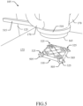
- FIG.3-FIG.4 different views are shown of the testing device 110 according to an embodiment of the present disclosure.
- the testing device 110 has a main body (for example, of plastic material) defining a holder 305.
- the holder 305 has a (bottom) resting surface 310 for resting the testing device 110 on any supporting surface, for example, the supporting surface 175 of the trolley of the imaging apparatus, not shown in the figure; the holder 305 has a (top) imaging surface 315 opposite the resting surface 310 for imaging the testing device 110.
- One or more seats 320 (four in this specific implementation, only one visible in the figure) are provided in the holder 305.
- the seats 320 are configured to accommodate corresponding containers 325 (one shown outside the seat 320 and three shown inside the seats 320 in the figure).
- each window 330 exposes part of the corresponding seat 320; therefore, each window 330 also exposes a corresponding part of the container 325 accommodated in the seat 320 so as to allow imaging its fluorescence agent.
- at least the part of the container 325 exposed through the window 330 is transparent to both the excitation light and the fluorescence light (i.e., it is capable of allowing the excitation/fluorescence light to pass through it substantially without being excessively diffused, such as with a ratio, between the radiant power of a beam of excitation/fluorescence light exiting the container 325 in a direction defined by a corresponding angle of refraction and the radiant power of a beam of excitation/fluorescence light entering the same container 325 being slanted with respect to its surface, higher than 80%, preferably higher than 85% and even more preferably higher than 90%, such as between 95% and 100%).
- FIG.4 it shows a cross-section view of the same testing device 110; particularly, the cross-section view is in a (vertical) symmetry plane, perpendicular to the resting surface 310, of two opposed seats 320 (one with the container 325 outside it and the other one with the container 325 inside it in the figure).
- the seats 320 are inclined with respect to the resting surface 310 ( i.e., a longitudinal axis thereof is not parallel to the resting surface 310). Because of the inclination of the seats 320, the containers 325 accommodated therein are inclined with respect to the resting surface 315 as well.
- any impurities that may be present in the containers 325 naturally flow upwards and accumulate there, away from the corresponding windows 330. This ensures that the parts of the containers 325 that are imaged through the windows 330 are substantially free of impurities.
- the containers 325 may not be filled completely; in this case as well, air remaining in the containers 325 flows upwards and accumulate there, away from the corresponding windows 330. This ensures that the parts of the containers 325 that are imaged through the windows 330 are substantially full of the fluorescence agent.
- a distance of the windows 330 (i.e., their upper borders) from the distal end of the corresponding seats 320 is 10-50%, preferably 20-40% and still more preferably 25-35%, such as 30% of a length of the seats 320 (along their longitudinal axis). These values of the distance ensure that any impurities and/or air in the containers 325 are never imagined through the windows 330 in most practical situations.
- Each seat 320 has an external portion 405 with a constant section (for example, with a cylindrical shape) and an internal portion 410 with a section decreasing moving inwards the holder 305 (for example, with a frusto-conical shape).
- the corresponding window 330 exposes at least part of the external portion 405 of the seat 320.
- the containers 325 accommodated in the seats 320 have a matching shape.
- the containers 325 are commercial off-the-shelf vials of 1.5 ml.
- Each vial 325 comprises a (transparent) elongated bottle 415 (such as of plastic material) containing the liquid with the fluorescence agent.
- the bottle 415 has a top portion 420 (proximal to an opening thereof) with a constant section (for example, with a cylindrical shape) and a bottom portion 425 (distal from the opening) with a section decreasing moving away from the opening (for example, with a frusto-conical shape).
- Each vial 325 further comprises a cap 430 closing the bottle 415 (for example, of screw-on type). Therefore, the windows 330 expose at least part of the top portions 420 of the containers 325 (and particularly their lowest part). In this way, the containers 325 are imaged where they are substantially flat.
- the windows 330 are opened in portions of the imaging surface 315 that are inclined with respect to the resting surface 310.
- the portions of the imaging surface 315 around the windows 330 are oriented inwards the holder 305 (downwards) moving towards its central point, so as to form an angle with the resting surface 310 of 5-15° (such as 10°). This reduces a reflection of the imaging surface 315 (at least close to the windows 330) when the testing device 110 is illuminated from above.
- one or more of the markers 340,345 encode (unique) container identifiers of the types of containers 325 to be accommodated in the seats 320 (for example, with each container identifier encoded in a corresponding marker 345 close to its seat 320).
- the container identifiers allow verifying the correct configuration of the testing device 110.
- the holder 305 has corresponding seat indicators 355 on the imaging surface 315 (for example, formed by corresponding labels stitched thereon), which are human-readable (for example, in text form).
- the seat indicators 355 are arranged in correspondence to the seats 320 and provide a specification of the types of containers 325 to be accommodated therein.
- the seat indicators 355 are color-coded; for example, the seat indicators 355 contain color names corresponding to the types of containers 325 (such as white, yellow, blue and green for increasing concentrations of a same fluorescence agent).
- the seat indicators 355 facilitate the insertion of the correct types of containers 325 into the seats 320 (especially when the testing device 110 is assembled on the field).
- the containers 325 have corresponding container indicators, which are human-readable (for example, colors).
- the container indicators are arranged on parts of the containers 325 projecting from the seats 320 when the containers 325 are inserted therein (so as to remain visible) and provide a specification of their types. Particularly, the container indicators are again color-coded.
- the caps 430 are colored according to the types of containers 320 as above, i.e., white, yellow, blue and green for increasing concentrations of the fluorescence agent (in this case, discernible by people affected by protanopia as well).
- the container indicators further facilitate the insertion of the correct types of containers 325 in the corresponding seats 320; moreover, they also allow verifying that the testing device 110 has been assembled correctly at any time.
- the imaging apparatus 105 has a holding station 505, which is used to hold the testing device 110 in a fixed (imaging) position on the supporting surface 175; the testing device 110 is held in the imaging position in a removable way.
- the holding station 505 is formed by a recess matching a footprint of the testing device 110 (defined by its resting surface, not visible in the figure), possibly with the addition of four lateral hollows for avoiding any interference of the parts of the containers 325 projecting from the holder 305; in this way, the testing device 110 may be inserted into the holding station 505 by dropping it into the recess.
- the recess has a depth lower than a height of the holder 305; in this way, the testing device 110 may be removed from the holding station 505 by grasping and lifting it from the recess.
- the testing device 110 When the testing device 110 is in the imaging position (defined by the holding station 505) and the imaging head 165 is in the acquisition position (defined by the holding station 510), the testing device 110 falls within the field of view of the imaging head 165. Particularly, the central point of the holder 305 is on the optical axis of the imaging head 165. This provides a controlled and repeatable illumination of the testing device 110.
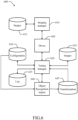
- a testing manager 620 manages any tests of the imaging apparatus.
- the testing manager 620 as well interfaces with the drives 605.
- the testing manager 620 accesses (in read/write mode) an image repository 625, a configuration repository 630 and a log repository 635.
- the image repository 625 stores one or more fluorescence images and photograph images that are acquired during a test of the imaging apparatus that is in progress.
- the configuration repository 630 stores configuration information for the tests of the imagining apparatus.
- the configuration information comprises a network address (such as a domain name) of a remote service provider (for example, a server of a manufacturer of the imaging apparatus), a descriptor of the testing device and a descriptor of the containers.
- the descriptor of the testing device indicates it by the corresponding device identifier.
- the descriptor of the testing device defines its configuration, i.e., free or fixed.
- the descriptor of the testing device defines its geometry; for example, the geometry of the testing device is defined in terms of shape of its holder and in terms of position of the windows, the markers, the seat indicators and the caps with respect to the holder ( i.e., their real-word coordinates in a reference system integral therewith).
- the descriptor of the testing device defines a specification of the containers for the markers, the seat indicators and the container indicators; for example, for each possible type of container there are provided its container identifier for the markers, its color name for the corresponding seat indicator and its color definition for the corresponding container indicator (the latter in terms of nominal values of one or more statistical parameters relating thereto, such mean value of color components, like RGB components).
- the descriptor of the testing device defines one or more usage rules thereof (for example, maximum usage in terms of length of the tests, maximum elapsed time from a production date and so on).
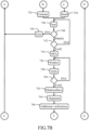
- FIG.7A-FIG.7C an activity diagram is shown describing the flow of activities relating to an implementation of the solution according to an embodiment of the present disclosure.
- the testing manager at block 706 turns on the white light source and the excitation light source, and it commands the photograph camera and the fluorescence camera to acquire a photograph image and a fluorescence image, respectively, of their same field of view (via the corresponding drives), after that the testing manager turns off the white light source and the excitation light source.
- the photograph image is defined by a bitmap comprising a matrix of cells (for example, with 512 rows and 512 columns) each storing a value of a pixel, i.e., a basic picture element corresponding to a location of the field of view, which pixel value represents the visible light reflected by the location (such as its RGB components).
- the testing manager downloads (further) usage information of the testing device from the service provider (from its network address retrieved from the configuration repository) according to its device identifier (assuming that it matches the one stored in the configuration repository); for example, this usage information may comprise an authenticity indicator of the testing device and its production date.
- the testing manager at block 730 verifies the usage information (retrieved and/or downloaded) against the usage rules (retrieved from the configuration repository); for example, the testing manager compares the length of the tests (since the last change of the testing device or of its containers) and/or a time elapsed from the production date with the corresponding maximum allowable values. The testing monitor then enables the test according to a result of this verification.
- the testing manager at block 752 verifies whether a last seat has been processed. If not, the process returns to the block 746 to repeat the same operations for a next seat. Conversely, once all the seats have been processed (determining that all the containers of the expected types are arranged therein), the loop is exit by descending into block 754.
- the testing device may have a spatial resolution target on its imaging surface (for example, the 1951 USAF, IEEE or ISO one), which is further specified in the configuration repository; in this case, the object recognition engine searches for the spatial resolution target (i.e., its representation in a corresponding ROI) in the photograph image, and the testing manager then determines the spatial resolution of the acquisition unit according thereto.
- the testing device may have a color test target on its imaging surface (either distinct or combined with the spatial resolution target), which is further specified in the configuration repository; in this case, the object recognition engine searches for the color test target ( i.e., its representation in a corresponding ROI) in the photograph image, and the testing manager then determines the color resolution of the acquisition unit according thereto.
- the testing device may have a reflectance standard on its imaging surface (either distinct or combined with the spatial resolution target and/or the color target), which is further specified in the configuration repository.
- the object recognition engine searches for the reflectance standard (i.e., its representation in a corresponding ROI) in the photograph image.
- the testing manager determines an ambient light as a difference between the white light generated by the white light source (as further defined in the configuration repository in terms of one or more statistical parameters relating thereto, such as its mean intensity) and a corresponding reflected light received from the reflectance standard (as defined by the same statistical parameters for the pixel values representing it in the photograph image, i . e ., mean intensity in the example at issue).
- the testing manager compares the ambient light (defined by the values of the statistical parameters for the reflected light minus the values of the corresponding statistical parameters for the white light) with a pre-defined threshold (such as 1-5% of the values of the statistical parameters for the white light).
- a pre-defined threshold such as 1-5% of the values of the statistical parameters for the white light.
- the same operation may also be performed by determining the ambient light as a difference between the excitation light generated by the excitation light source (as further defined in the configuration repository in terms of one or more statistical parameters relating thereto, such as its mean intensity) and a corresponding (further) reflected light received from the reflectance standard (as defined by the same statistical parameters for the pixel values representing it in the fluorescence image, i.e., mean intensity in the example at issue). This allows verifying that the ambient conditions are suitable for correct operation of the imaging apparatus. In any case, the testing manager adds a result of these verifications to the temporary record of the test.
- the testing manager conditions the statistical parameters (mean fluorescence intensity) calculated above for the pixel values representing each window in the previous fluorescence image (step 754) according to the difference between the same mean fluorescence intensity of the (current) fluorescence image and its nominal value (so as to remove the effect of any mismatch of the acquisition unit); the testing manager then verifies again whether each window matches the fluorescence light emitted by the container arranged in the corresponding seat as above (steps 756-760). The testing manager adds a result of this verification to the temporary record of the test.
- the statistical parameters mean fluorescence intensity
- the longitudinal axes of the seats form an angle of 5-30° with the resting surface.
- a distance of the corresponding windows from the first ends of the seats is 10-50% of a length of the seats.
- the possibility is not excluded of having the windows at different distance from these ends of the seats.
- the seats comprise corresponding blind holes extending inwards from the lateral surface.
- the possibility is not excluded of having the seats formed in another way (for example, by through-holes, recesses and so on).
- the corresponding window exposes at least part of the first portion.
- the window may expose any part of the first portion (up to completely).
- the windows have corresponding edges at the imaging surface that are chamfered.
- the chamfered edges may form any angle with the imaging surface.
- the testing device has a point symmetry with respect to a central point.
- the testing device may have any shape with point symmetry (for example, octagonal, hexagonal, squared, circular and so on).
- the bottom surface is parallel to the resting surface.
- the possibility is not excluded of having the bottom surface inclined with respect to the resting surface.
- the container indicators are color-coded.
- the colors may be of any type and indicated in any way (for example, with the end portions themselves that are colored, with labels with their names, samples and so on).
- the method comprises calculating a position of the windows in the photograph image according to the position of the testing device in the photograph image and the position of the windows in the testing device.
- the position of the windows in the photograph image may be calculated in any way (for example, by determining and then applying any transformation between real-word coordinates and image coordinates, such as of affine or non-rigid type, defined by a matrix, a transform, a vector and so on).
- the method comprises testing the luminescence imaging apparatus according to a comparison of the representation of each of the windows in the luminescence image with the representation of the background area in the luminescence image.
- this operation may be performed in any way (either the same or different with respect to the comparison with the other windows).
- the method comprises testing the luminescence imaging apparatus according to the device information.
- the device information may be used in any way (for example, to determine expected type of containers, to retrieve usage rules, to retrieve usage information and so on).
- the method comprises determining a representation of the end portions of the containers in the photograph image.
- the end portions may be determined in any way (for example, according to the position of the testing device and to the descriptor comprising an indication of a position of the end portions in the testing device, by searching them directly and so on).
- the method comprises verifying a configuration of the testing device according to a matching of the representation of the end portions in the photograph image with pre-defined definitions of the corresponding expected types of the containers.
- the definitions of the types of containers may be of any type (for example, color definitions given by any number and type of statistical parameters, color names and so on) and they may be retrieved in any way (for example, locally or remotely); the verification of the configuration of the testing device may be performed accordingly in any way (for example, by comparing the difference of each statistical parameter individually or a global difference with any threshold, by comparing the names, with or without the further verification of the seat indicators, and so on).
- the method comprises retrieving usage information of one or more previous executions of said testing the luminescence imaging apparatus.
- the usage information may be of any type (for example, length of tests, number of tests, date of last test and so on) and it may be retrieved in any way (for example, locally or remotely, and so on).
- the method comprises enabling said testing the luminescence imaging apparatus according to the usage information.
- the test may be enabled according to the usage information in any way (for example, by verifying it against any usage rules as above, with the usage rules that may be pre-defined locally or remotely, retrieved according to the device identifier, and by enabling the test in any way according to the corresponding result as above, and so on).
- the method comprises retrieving the usage rules and/or the usage information according to the device information.
- the usage rules and the usage information may be retrieved in any way (for example, extracted directly from the device information, determined according thereto either locally or remotely, such as via a corresponding device identifier, and so on).
- the method comprises testing an acquisition unit of the imaging head (for acquiring the luminescence images) according to the further luminescence image and predefined characteristics of the testing light source.
- the acquisition unit may be of any type (see below);
- the characteristics of the testing light source may be of any type (for example, nominal values of any number and type of statistical parameters) and they may be retrieved in any way (for example, locally or remotely); moreover, the test may be performed accordingly in any way (for example, by comparing the difference of each statistical parameter individually or a global difference with any threshold, and so on).
- the method comprises determining a displacement of the testing device and/or the imaging head from a target position according to the position of the testing device in the photograph image.
- the displacement may be determined in any way (for example, for each coordinate or globally, and so on) from the position of the testing device defined in any way (for example, by the holder and/or the positional markers) to any target position thereof (for example, retrieved locally or remotely, inserted manually and so on); moreover, the displacement may be defined for the testing device alone, the imaging head alone or both of them.
- the method comprises outputting an indication of a movement of the testing device and/or the imaging head for reaching the target position according to the displacement thereof on an output unit of the luminescence imaging apparatus.
- the movement may be of any type (for example, translation and/or rotation in plane or space for the testing device alone, the imaging head alone or both of them, and so on); moreover, the indication of the movement may be output in any way (for example, displayed, uttered and so on) on any output unit (for example, monitor, loudspeaker and so on).
- This feature may be used for any purpose (for example, to arrange the testing device correctly, to test the fluorescence imaging apparatus throughout the field of view and so on).
- the method comprises repeating the following loop in a non-operative condition of the luminescence imaging apparatus.
- the loop may be repeated with any frequency in any non-operative condition (for example, when no imaging process is in progress as indicated by corresponding start and stop commands entered by the operator via any input unit, in stand-by and so on).
- the loop comprises acquiring a further photograph image of the field of view with the photograph camera.
- the further photograph image may be of any type (either the same or different with respect to the photograph image) and it may be acquired in any way (for example, alone or with a corresponding fluorescence image to be used for the test after exiting the loop, and so on).
- the method comprises triggering said testing the luminescence imaging apparatus in response to the representation of the testing device in the further photograph image being found.
- the test may be trigged in any way (for example, automatically or requiring a manual confirmation, with or without prompting the operator to enter information, and so on).
- the luminescence imaging apparatus comprises a supporting surface for resting the testing device.
- the supporting surface may be of any type (for example, a top surface of any trolley, a cantilever, either fixed or hidden, and so on).
- a center of the testing device in the imaging position is on an optical axis of the imaging head in the acquisition position.
- the possibility of having the testing device in one or more different positions is not excluded.
Landscapes
- Physics & Mathematics (AREA)
- Health & Medical Sciences (AREA)
- Life Sciences & Earth Sciences (AREA)
- Spectroscopy & Molecular Physics (AREA)
- General Physics & Mathematics (AREA)
- General Health & Medical Sciences (AREA)
- Pathology (AREA)
- Immunology (AREA)
- Biochemistry (AREA)
- Analytical Chemistry (AREA)
- Chemical & Material Sciences (AREA)
- Nuclear Medicine, Radiotherapy & Molecular Imaging (AREA)
- Medical Informatics (AREA)
- Animal Behavior & Ethology (AREA)
- Surgery (AREA)
- Public Health (AREA)
- Veterinary Medicine (AREA)
- Molecular Biology (AREA)
- Heart & Thoracic Surgery (AREA)
- Biomedical Technology (AREA)
- Engineering & Computer Science (AREA)
- Biophysics (AREA)
- Investigating, Analyzing Materials By Fluorescence Or Luminescence (AREA)
Claims (14)
- Dispositif de test (110) pour tester un appareil d'imagerie par luminescence (105), dans lequel le dispositif de test (110) comprend :une surface de repos (310) pour reposer le dispositif de test (110) sur une surface de support (175),un ou plusieurs sièges (320),un ou plusieurs récipients (325) chacun rempli d'un liquide comprenant au moins une substance luminescente, chacun des récipients (325) étant logé dans un siège correspondant (320),une ou plusieurs fenêtres (330) correspondant aux sièges (320) qui sont ouvertes dans une surface d'imagerie (315) du dispositif de test (110) opposée à la surface de repos (310), chacune des fenêtres (330) exposant une partie du siège correspondant (320) pour imager la substance luminescente d'une partie correspondante du récipient (325) logé dans celui-ci qui est transparente à une lumière d'excitation de la substance luminescente et à une lumière luminescente émise par la substance luminescente lorsqu'elle est éclairée par la lumière d'excitation,dans lequel les sièges (320) s'étendent le long d'axes longitudinaux correspondants depuis des premières extrémités correspondantes jusqu'à des deuxièmes extrémités correspondantes, chacun des sièges (320) étant incliné par rapport à la surface de repos (310) avec la deuxième extrémité plus proche de la surface de repos (310) que la première extrémité, et les axes longitudinaux des sièges (320) formant un angle de 5 à 30° avec la surface de repos (310), et en ce que les fenêtres correspondantes (330) sont espacées des premières extrémités des sièges (320).
- Dispositif de test (110) selon la revendication 1, dans lequel les axes longitudinaux des sièges (320) forment un angle de 10° avec la surface de repos (310).
- Dispositif de test (110) selon la revendication 1 ou 2, dans lequel les conteneurs correspondants (325) sont logés dans les sièges (320) de façon non amovible.
- Dispositif de test (110) selon la revendication 1 ou 2, dans lequel les conteneurs correspondants (325) sont logés dans les sièges (320) de façon amovible.
- Dispositif de test (110) selon l'une quelconque des revendications 1 à 4, dans lequel une distance entre les fenêtres correspondantes (320) et les premières extrémités des sièges (320) est de 10 à 50 % d'une longueur des sièges (320).
- Dispositif de test (110) selon l'une quelconque des revendications 1 à 5, dans lequel le dispositif de test (110) présente une surface latérale (335) qui s'étend entre la surface de repos (310) et la surface d'imagerie (315), les sièges (320) comprenant des orifices borgnes correspondants qui s'étendent vers l'intérieur à partir de la surface latérale (335).
- Dispositif de test (110) selon l'une quelconque des revendications 1 à 6, dans lequel les fenêtres (330) ont des bords correspondants au niveau de la surface d'imagerie (315) qui sont chanfreinés.
- Dispositif de test (110) selon l'une quelconque des revendications 1 à 7, dans lequel le dispositif de test (110) comprend un ou plusieurs éléments de verrouillage (435) pour verrouiller le dispositif de test (110) sur la surface de support.
- Dispositif de test (110) selon la revendication 8, dans lequel les éléments de verrouillage (435) comprennent des éléments magnétiques correspondants (435) disposés sur la surface de repos (310).
- Dispositif de test (110) selon l'une quelconque des revendications 1 à 9, dans lequel la surface d'imagerie (315) autour des fenêtres (330) est inclinée par rapport à la surface de repos (310).
- Dispositif de test (110) selon l'une quelconque des revendications 1 à 10, dans lequel le dispositif de test (110) comprend un ou plusieurs indicateurs de siège lisibles par un être humain (355) correspondant aux sièges (320), les indicateurs de siège (355) fournissant des spécifications correspondantes des types attendus des conteneurs (325) à loger dans les sièges (320).
- Dispositif de test (110) selon l'une quelconque des revendications 1 à 11, dans lequel le dispositif de test (110) comprend une source de lumière de test (350) au niveau de la surface d'imagerie (315) pour générer une lumière de test correspondant à la lumière de luminescence.
- Système d'imagerie par luminescence (100) comprenant un appareil d'imagerie par luminescence (105) et le dispositif de test (110) selon l'une quelconque des revendications 1 à 12, dans lequel l'appareil d'imagerie par luminescence (105) comprend :une tête d'imagerie (165) ayant un axe optique,une surface de support (175), le dispositif de test (110) reposant sur la surface de support (175),une station de maintien (505) pour maintenir le dispositif de test (110) dans une position d'imagerie sur la surface de support (175) de façon amovible, etune autre station de maintien (510) pour maintenir la tête d'imagerie (165) dans une position d'acquisition de façon amovible, dans lequel le dispositif de test (110) dans la position d'imagerie tombe dans le champ de vision de la tête d'imagerie (165) dans la position d'acquisition avec un centre du dispositif de test (110) sur un axe optique de la tête d'imagerie (165).
- Procédé (700) de test d'un appareil d'imagerie par luminescence (105) avec le dispositif de test (110) selon l'une quelconque des revendications 1 à 12 qui repose sur une surface de support (175), dans un champ de vision d'une tête d'imagerie (165) de l'appareil d'imagerie par luminescence (105), dans lequel le procédé (700) comprend, sous la commande d'une unité de commande (205) de l'appareil d'imagerie par luminescence (105) :l'acquisition (706), avec une caméra de luminescence (245) de la tête d'imagerie (165), d'une image de luminescence du champ de vision, l'image de luminescence étant représentative d'une lumière de luminescence émise par la substance de luminescence des conteneurs (325) en réponse à une lumière d'excitation de celle-ci fournie par une source de lumière d'excitation (210) de la tête d'imagerie (165),la détermination (708-752) d'une représentation des fenêtres (330) dans l'image de luminescence, etle test (754-786) de l'appareil d'imagerie par luminescence (105) en fonction de la représentation des fenêtres (330) dans l'image de luminescence.
Applications Claiming Priority (2)
| Application Number | Priority Date | Filing Date | Title |
|---|---|---|---|
| EP19211282 | 2019-11-25 | ||
| PCT/EP2020/082671 WO2021104987A1 (fr) | 2019-11-25 | 2020-11-19 | Essai d'appareil d'imagerie par luminescence avec récipients inclinés de substances luminescentes |
Publications (3)
| Publication Number | Publication Date |
|---|---|
| EP4065955A1 EP4065955A1 (fr) | 2022-10-05 |
| EP4065955B1 true EP4065955B1 (fr) | 2025-04-16 |
| EP4065955C0 EP4065955C0 (fr) | 2025-04-16 |
Family
ID=68655418
Family Applications (1)
| Application Number | Title | Priority Date | Filing Date |
|---|---|---|---|
| EP20823735.4A Active EP4065955B1 (fr) | 2019-11-25 | 2020-11-19 | Test d'un appareil d'imagerie par luminescence avec des récipients inclinés de substances luminescentes |
Country Status (5)
| Country | Link |
|---|---|
| US (1) | US12320750B2 (fr) |
| EP (1) | EP4065955B1 (fr) |
| JP (1) | JP7587577B2 (fr) |
| CN (1) | CN114631017A (fr) |
| WO (1) | WO2021104987A1 (fr) |
Families Citing this family (2)
| Publication number | Priority date | Publication date | Assignee | Title |
|---|---|---|---|---|
| WO2021104985A1 (fr) * | 2019-11-25 | 2021-06-03 | Surgvision Gmbh | Essai d'un appareil d'imagerie par luminescence avec détection automatique d'un dispositif d'essai |
| WO2025186147A1 (fr) * | 2024-03-07 | 2025-09-12 | Trinamix Gmbh | Appareil et procédé de traitement de données de mesure de spectromètre, dispositif mobile, serveur et procédé de détermination de plausibilité pour des données de mesure de spectromètre à temps d'exécution |
Family Cites Families (10)
| Publication number | Priority date | Publication date | Assignee | Title |
|---|---|---|---|---|
| JP2605179Y2 (ja) * | 1993-09-27 | 2000-06-26 | 株式会社久保田製作所 | 遠心分離機用アングルロータとチューブ保持板 |
| US6919919B2 (en) | 2002-02-06 | 2005-07-19 | Xenogen Corporation | Light calibration device for use in low level light imaging systems |
| US8220415B2 (en) | 2007-09-05 | 2012-07-17 | Li-Cor, Inc. | Modular animal imaging apparatus |
| US8373860B2 (en) * | 2008-02-01 | 2013-02-12 | Palo Alto Research Center Incorporated | Transmitting/reflecting emanating light with time variation |
| US8432530B2 (en) * | 2008-07-22 | 2013-04-30 | Canon Kabushiki Kaisha | Device, method, and system for measuring image profiles produced by an optical lithography system |
| AU2009296526B2 (en) * | 2008-09-24 | 2015-11-19 | First Light Diagnostics, Inc. | Method for detecting analytes |
| KR20120080056A (ko) | 2011-01-06 | 2012-07-16 | 삼성전자주식회사 | 디스크 및 이를 이용한 검사장치의 보정방법 |
| US9167240B1 (en) | 2012-12-12 | 2015-10-20 | Board Of Regents Of The University Of Texas System | Methods and compositions for validation of fluorescence imaging and tomography devices |
| JP6161072B2 (ja) * | 2013-12-26 | 2017-07-12 | 国立研究開発法人産業技術総合研究所 | 多チャンネル式化学発光計測システム |
| CN109154570A (zh) | 2016-05-19 | 2019-01-04 | 浜松光子学株式会社 | 荧光测定装置的校正用基准体 |
-
2020
- 2020-11-19 US US17/779,516 patent/US12320750B2/en active Active
- 2020-11-19 WO PCT/EP2020/082671 patent/WO2021104987A1/fr not_active Ceased
- 2020-11-19 CN CN202080075308.6A patent/CN114631017A/zh active Pending
- 2020-11-19 JP JP2022524579A patent/JP7587577B2/ja active Active
- 2020-11-19 EP EP20823735.4A patent/EP4065955B1/fr active Active
Also Published As
| Publication number | Publication date |
|---|---|
| WO2021104987A1 (fr) | 2021-06-03 |
| EP4065955A1 (fr) | 2022-10-05 |
| US12320750B2 (en) | 2025-06-03 |
| JP7587577B2 (ja) | 2024-11-20 |
| CN114631017A (zh) | 2022-06-14 |
| EP4065955C0 (fr) | 2025-04-16 |
| US20230003650A1 (en) | 2023-01-05 |
| JP2023502867A (ja) | 2023-01-26 |
Similar Documents
| Publication | Publication Date | Title |
|---|---|---|
| US12618775B2 (en) | Testing of luminescence imaging apparatus with automatic detection of a testing device | |
| ES2555992T3 (es) | Sistema y procedimiento para analizar al menos una característica de la piel | |
| US20210263018A1 (en) | Lateral flow test strip immunoassay in vitro diagnostic device | |
| US8057041B2 (en) | Apparatus for measuring an analyte in an eye fluid | |
| US8046055B2 (en) | Lymph node detector | |
| US8094916B2 (en) | Biological growth plate scanner | |
| EP2529204B1 (fr) | Analyse de brillance de pierres précieuses | |
| US12320750B2 (en) | Testing of a luminescence imaging apparatus with inclined containers of luminescence substance | |
| DK2769359T3 (en) | DATA PROCESSING SYSTEMS AND PROCEDURES FOR ELECTRONIC STATEMENT OF THE LIABILITY OF A PRODUCT | |
| ES2587236T3 (es) | Identificación y verificación de medicación | |
| JP6210813B2 (ja) | 光源モジュール、および試料を分析するための分析機器 | |
| US20070042346A1 (en) | Method and apparatus for detection of rare cells | |
| US10527838B2 (en) | Analysis device, microscope device, analysis method, and program | |
| US20090135603A1 (en) | Back side plate illumination for biological growth plate scanner | |
| JP2018534557A (ja) | Ivdアッセイを読み取るためのデバイス | |
| JP2019106944A (ja) | 観察装置及びそれを用いた観察方法 | |
| ES2331055T3 (es) | Dispositivo para la observacion secuencial de muestras y procedimientos que utiliza. | |
| JP2010534837A (ja) | 顕微鏡対象物を検査するための装置用のコンピュータ制御可能なled光源 | |
| CN114441260B (zh) | 载片架确定系统 | |
| US10927404B1 (en) | Pathogen detection using aptamer molecular beacons using a mobile device | |
| ES2638238T3 (es) | Aparato y método para localizar un objeto | |
| US20230184679A1 (en) | Pathogen detection using aptamer molecular photonic beacons | |
| GB2576175A (en) | An apparatus and method for providing visual signals relating to a plurality of laboratory sample carriers | |
| US20240280501A1 (en) | Systems, devices, and methods for diagnostics measurements | |
| JP4983929B2 (ja) | 生体画像取得装置 |
Legal Events
| Date | Code | Title | Description |
|---|---|---|---|
| STAA | Information on the status of an ep patent application or granted ep patent |
Free format text: STATUS: UNKNOWN |
|
| STAA | Information on the status of an ep patent application or granted ep patent |
Free format text: STATUS: THE INTERNATIONAL PUBLICATION HAS BEEN MADE |
|
| PUAI | Public reference made under article 153(3) epc to a published international application that has entered the european phase |
Free format text: ORIGINAL CODE: 0009012 |
|
| STAA | Information on the status of an ep patent application or granted ep patent |
Free format text: STATUS: REQUEST FOR EXAMINATION WAS MADE |
|
| 17P | Request for examination filed |
Effective date: 20220613 |
|
| AK | Designated contracting states |
Kind code of ref document: A1 Designated state(s): AL AT BE BG CH CY CZ DE DK EE ES FI FR GB GR HR HU IE IS IT LI LT LU LV MC MK MT NL NO PL PT RO RS SE SI SK SM TR |
|
| DAV | Request for validation of the european patent (deleted) | ||
| DAX | Request for extension of the european patent (deleted) | ||
| STAA | Information on the status of an ep patent application or granted ep patent |
Free format text: STATUS: EXAMINATION IS IN PROGRESS |
|
| P01 | Opt-out of the competence of the unified patent court (upc) registered |
Effective date: 20230517 |
|
| 17Q | First examination report despatched |
Effective date: 20230601 |
|
| REG | Reference to a national code |
Ref country code: DE Ref legal event code: R079 Free format text: PREVIOUS MAIN CLASS: G01N0021000000 Ipc: G01J0003020000 Ref country code: DE Ref legal event code: R079 Ref document number: 602020049646 Country of ref document: DE Free format text: PREVIOUS MAIN CLASS: G01N0021000000 Ipc: G01J0003020000 |
|
| GRAP | Despatch of communication of intention to grant a patent |
Free format text: ORIGINAL CODE: EPIDOSNIGR1 |
|
| STAA | Information on the status of an ep patent application or granted ep patent |
Free format text: STATUS: GRANT OF PATENT IS INTENDED |
|
| RIC1 | Information provided on ipc code assigned before grant |
Ipc: A61B 5/00 20060101ALI20241114BHEP Ipc: G01N 21/00 20060101ALI20241114BHEP Ipc: G01J 3/443 20060101ALI20241114BHEP Ipc: G01J 3/02 20060101AFI20241114BHEP |
|
| INTG | Intention to grant announced |
Effective date: 20241203 |
|
| GRAS | Grant fee paid |
Free format text: ORIGINAL CODE: EPIDOSNIGR3 |
|
| GRAA | (expected) grant |
Free format text: ORIGINAL CODE: 0009210 |
|
| STAA | Information on the status of an ep patent application or granted ep patent |
Free format text: STATUS: THE PATENT HAS BEEN GRANTED |
|
| AK | Designated contracting states |
Kind code of ref document: B1 Designated state(s): AL AT BE BG CH CY CZ DE DK EE ES FI FR GB GR HR HU IE IS IT LI LT LU LV MC MK MT NL NO PL PT RO RS SE SI SK SM TR |
|
| REG | Reference to a national code |
Ref country code: GB Ref legal event code: FG4D |
|
| REG | Reference to a national code |
Ref country code: CH Ref legal event code: EP |
|
| REG | Reference to a national code |
Ref country code: IE Ref legal event code: FG4D |
|
| REG | Reference to a national code |
Ref country code: DE Ref legal event code: R096 Ref document number: 602020049646 Country of ref document: DE |
|
| U01 | Request for unitary effect filed |
Effective date: 20250514 |
|
| U07 | Unitary effect registered |
Designated state(s): AT BE BG DE DK EE FI FR IT LT LU LV MT NL PT RO SE SI Effective date: 20250520 |
|
| P04 | Withdrawal of opt-out of the competence of the unified patent court (upc) registered |
Free format text: CASE NUMBER: APP_23411/2025 Effective date: 20250516 |
|
| PG25 | Lapsed in a contracting state [announced via postgrant information from national office to epo] |
Ref country code: ES Free format text: LAPSE BECAUSE OF FAILURE TO SUBMIT A TRANSLATION OF THE DESCRIPTION OR TO PAY THE FEE WITHIN THE PRESCRIBED TIME-LIMIT Effective date: 20250416 |
|
| PG25 | Lapsed in a contracting state [announced via postgrant information from national office to epo] |
Ref country code: NO Free format text: LAPSE BECAUSE OF FAILURE TO SUBMIT A TRANSLATION OF THE DESCRIPTION OR TO PAY THE FEE WITHIN THE PRESCRIBED TIME-LIMIT Effective date: 20250716 Ref country code: GR Free format text: LAPSE BECAUSE OF FAILURE TO SUBMIT A TRANSLATION OF THE DESCRIPTION OR TO PAY THE FEE WITHIN THE PRESCRIBED TIME-LIMIT Effective date: 20250717 |
|
| PG25 | Lapsed in a contracting state [announced via postgrant information from national office to epo] |
Ref country code: PL Free format text: LAPSE BECAUSE OF FAILURE TO SUBMIT A TRANSLATION OF THE DESCRIPTION OR TO PAY THE FEE WITHIN THE PRESCRIBED TIME-LIMIT Effective date: 20250416 |
|
| PG25 | Lapsed in a contracting state [announced via postgrant information from national office to epo] |
Ref country code: HR Free format text: LAPSE BECAUSE OF FAILURE TO SUBMIT A TRANSLATION OF THE DESCRIPTION OR TO PAY THE FEE WITHIN THE PRESCRIBED TIME-LIMIT Effective date: 20250416 |
|
| PG25 | Lapsed in a contracting state [announced via postgrant information from national office to epo] |
Ref country code: RS Free format text: LAPSE BECAUSE OF FAILURE TO SUBMIT A TRANSLATION OF THE DESCRIPTION OR TO PAY THE FEE WITHIN THE PRESCRIBED TIME-LIMIT Effective date: 20250716 |
|
| PG25 | Lapsed in a contracting state [announced via postgrant information from national office to epo] |
Ref country code: IS Free format text: LAPSE BECAUSE OF FAILURE TO SUBMIT A TRANSLATION OF THE DESCRIPTION OR TO PAY THE FEE WITHIN THE PRESCRIBED TIME-LIMIT Effective date: 20250816 |
|
| REG | Reference to a national code |
Ref country code: CH Ref legal event code: U11 Free format text: ST27 STATUS EVENT CODE: U-0-0-U10-U11 (AS PROVIDED BY THE NATIONAL OFFICE) Effective date: 20251201 |
|
| U20 | Renewal fee for the european patent with unitary effect paid |
Year of fee payment: 6 Effective date: 20251126 |
|
| PGFP | Annual fee paid to national office [announced via postgrant information from national office to epo] |
Ref country code: GB Payment date: 20251127 Year of fee payment: 6 |
|
| PG25 | Lapsed in a contracting state [announced via postgrant information from national office to epo] |
Ref country code: SM Free format text: LAPSE BECAUSE OF FAILURE TO SUBMIT A TRANSLATION OF THE DESCRIPTION OR TO PAY THE FEE WITHIN THE PRESCRIBED TIME-LIMIT Effective date: 20250416 |
|
| PGFP | Annual fee paid to national office [announced via postgrant information from national office to epo] |
Ref country code: CH Payment date: 20251201 Year of fee payment: 6 |
|
| PG25 | Lapsed in a contracting state [announced via postgrant information from national office to epo] |
Ref country code: CZ Free format text: LAPSE BECAUSE OF FAILURE TO SUBMIT A TRANSLATION OF THE DESCRIPTION OR TO PAY THE FEE WITHIN THE PRESCRIBED TIME-LIMIT Effective date: 20250416 |
|
| PG25 | Lapsed in a contracting state [announced via postgrant information from national office to epo] |
Ref country code: SK Free format text: LAPSE BECAUSE OF FAILURE TO SUBMIT A TRANSLATION OF THE DESCRIPTION OR TO PAY THE FEE WITHIN THE PRESCRIBED TIME-LIMIT Effective date: 20250416 |
|
| PLBE | No opposition filed within time limit |
Free format text: ORIGINAL CODE: 0009261 |
|
| STAA | Information on the status of an ep patent application or granted ep patent |
Free format text: STATUS: NO OPPOSITION FILED WITHIN TIME LIMIT |
|
| REG | Reference to a national code |
Ref country code: CH Ref legal event code: L10 Free format text: ST27 STATUS EVENT CODE: U-0-0-L10-L00 (AS PROVIDED BY THE NATIONAL OFFICE) Effective date: 20260225 |
|
| 26N | No opposition filed |
Effective date: 20260119 |