EP4067096B1 - Bilderzeugungsgerät, bilderzeugungsverfahren und trägermedium - Google Patents
Bilderzeugungsgerät, bilderzeugungsverfahren und trägermedium Download PDFInfo
- Publication number
- EP4067096B1 EP4067096B1 EP22162627.8A EP22162627A EP4067096B1 EP 4067096 B1 EP4067096 B1 EP 4067096B1 EP 22162627 A EP22162627 A EP 22162627A EP 4067096 B1 EP4067096 B1 EP 4067096B1
- Authority
- EP
- European Patent Office
- Prior art keywords
- main scanning
- scanning movement
- ink
- image forming
- color ink
- Prior art date
- Legal status (The legal status is an assumption and is not a legal conclusion. Google has not performed a legal analysis and makes no representation as to the accuracy of the status listed.)
- Active
Links
Images




Classifications
-
- B—PERFORMING OPERATIONS; TRANSPORTING
- B41—PRINTING; LINING MACHINES; TYPEWRITERS; STAMPS
- B41J—TYPEWRITERS; SELECTIVE PRINTING MECHANISMS, i.e. MECHANISMS PRINTING OTHERWISE THAN FROM A FORME; CORRECTION OF TYPOGRAPHICAL ERRORS
- B41J11/00—Devices or arrangements of selective printing mechanisms, e.g. ink-jet printers or thermal printers, for supporting or handling copy material in sheet or web form
- B41J11/0015—Devices or arrangements of selective printing mechanisms, e.g. ink-jet printers or thermal printers, for supporting or handling copy material in sheet or web form for treating before, during or after printing or for uniform coating or laminating the copy material before or after printing
- B41J11/002—Curing or drying the ink on the copy materials, e.g. by heating or irradiating
- B41J11/0021—Curing or drying the ink on the copy materials, e.g. by heating or irradiating using irradiation
- B41J11/00214—Curing or drying the ink on the copy materials, e.g. by heating or irradiating using irradiation using UV radiation
-
- B—PERFORMING OPERATIONS; TRANSPORTING
- B41—PRINTING; LINING MACHINES; TYPEWRITERS; STAMPS
- B41J—TYPEWRITERS; SELECTIVE PRINTING MECHANISMS, i.e. MECHANISMS PRINTING OTHERWISE THAN FROM A FORME; CORRECTION OF TYPOGRAPHICAL ERRORS
- B41J11/00—Devices or arrangements of selective printing mechanisms, e.g. ink-jet printers or thermal printers, for supporting or handling copy material in sheet or web form
- B41J11/0015—Devices or arrangements of selective printing mechanisms, e.g. ink-jet printers or thermal printers, for supporting or handling copy material in sheet or web form for treating before, during or after printing or for uniform coating or laminating the copy material before or after printing
- B41J11/002—Curing or drying the ink on the copy materials, e.g. by heating or irradiating
- B41J11/0021—Curing or drying the ink on the copy materials, e.g. by heating or irradiating using irradiation
-
- B—PERFORMING OPERATIONS; TRANSPORTING
- B41—PRINTING; LINING MACHINES; TYPEWRITERS; STAMPS
- B41J—TYPEWRITERS; SELECTIVE PRINTING MECHANISMS, i.e. MECHANISMS PRINTING OTHERWISE THAN FROM A FORME; CORRECTION OF TYPOGRAPHICAL ERRORS
- B41J11/00—Devices or arrangements of selective printing mechanisms, e.g. ink-jet printers or thermal printers, for supporting or handling copy material in sheet or web form
- B41J11/0015—Devices or arrangements of selective printing mechanisms, e.g. ink-jet printers or thermal printers, for supporting or handling copy material in sheet or web form for treating before, during or after printing or for uniform coating or laminating the copy material before or after printing
- B41J11/002—Curing or drying the ink on the copy materials, e.g. by heating or irradiating
- B41J11/0021—Curing or drying the ink on the copy materials, e.g. by heating or irradiating using irradiation
- B41J11/00218—Constructional details of the irradiation means, e.g. radiation source attached to reciprocating print head assembly or shutter means provided on the radiation source
-
- B—PERFORMING OPERATIONS; TRANSPORTING
- B41—PRINTING; LINING MACHINES; TYPEWRITERS; STAMPS
- B41J—TYPEWRITERS; SELECTIVE PRINTING MECHANISMS, i.e. MECHANISMS PRINTING OTHERWISE THAN FROM A FORME; CORRECTION OF TYPOGRAPHICAL ERRORS
- B41J11/00—Devices or arrangements of selective printing mechanisms, e.g. ink-jet printers or thermal printers, for supporting or handling copy material in sheet or web form
- B41J11/22—Paper-carriage guides or races
-
- B—PERFORMING OPERATIONS; TRANSPORTING
- B41—PRINTING; LINING MACHINES; TYPEWRITERS; STAMPS
- B41J—TYPEWRITERS; SELECTIVE PRINTING MECHANISMS, i.e. MECHANISMS PRINTING OTHERWISE THAN FROM A FORME; CORRECTION OF TYPOGRAPHICAL ERRORS
- B41J2/00—Typewriters or selective printing mechanisms characterised by the printing or marking process for which they are designed
- B41J2/005—Typewriters or selective printing mechanisms characterised by the printing or marking process for which they are designed characterised by bringing liquid or particles selectively into contact with a printing material
- B41J2/01—Ink jet
- B41J2/21—Ink jet for multi-colour printing
- B41J2/2107—Ink jet for multi-colour printing characterised by the ink properties
-
- B—PERFORMING OPERATIONS; TRANSPORTING
- B41—PRINTING; LINING MACHINES; TYPEWRITERS; STAMPS
- B41J—TYPEWRITERS; SELECTIVE PRINTING MECHANISMS, i.e. MECHANISMS PRINTING OTHERWISE THAN FROM A FORME; CORRECTION OF TYPOGRAPHICAL ERRORS
- B41J25/00—Actions or mechanisms not otherwise provided for
- B41J25/001—Mechanisms for bodily moving print heads or carriages parallel to the paper surface
-
- B—PERFORMING OPERATIONS; TRANSPORTING
- B41—PRINTING; LINING MACHINES; TYPEWRITERS; STAMPS
- B41J—TYPEWRITERS; SELECTIVE PRINTING MECHANISMS, i.e. MECHANISMS PRINTING OTHERWISE THAN FROM A FORME; CORRECTION OF TYPOGRAPHICAL ERRORS
- B41J25/00—Actions or mechanisms not otherwise provided for
- B41J25/304—Bodily-movable mechanisms for print heads or carriages movable towards or from paper surface
- B41J25/316—Bodily-movable mechanisms for print heads or carriages movable towards or from paper surface with tilting motion mechanisms relative to paper surface
-
- B—PERFORMING OPERATIONS; TRANSPORTING
- B41—PRINTING; LINING MACHINES; TYPEWRITERS; STAMPS
- B41M—PRINTING, DUPLICATING, MARKING, OR COPYING PROCESSES; COLOUR PRINTING
- B41M3/00—Printing processes to produce particular kinds of printed work, e.g. patterns
- B41M3/008—Sequential or multiple printing, e.g. on previously printed background; Mirror printing; Recto-verso printing; using a combination of different printing techniques; Printing of patterns visible in reflection and by transparency; by superposing printed artifacts
-
- B—PERFORMING OPERATIONS; TRANSPORTING
- B41—PRINTING; LINING MACHINES; TYPEWRITERS; STAMPS
- B41M—PRINTING, DUPLICATING, MARKING, OR COPYING PROCESSES; COLOUR PRINTING
- B41M5/00—Duplicating or marking methods; Sheet materials for use therein
- B41M5/0023—Digital printing methods characterised by the inks used
-
- B—PERFORMING OPERATIONS; TRANSPORTING
- B41—PRINTING; LINING MACHINES; TYPEWRITERS; STAMPS
- B41M—PRINTING, DUPLICATING, MARKING, OR COPYING PROCESSES; COLOUR PRINTING
- B41M7/00—After-treatment of prints, e.g. heating, irradiating, setting of the ink, protection of the printed stock
- B41M7/0081—After-treatment of prints, e.g. heating, irradiating, setting of the ink, protection of the printed stock using electromagnetic radiation or waves, e.g. ultraviolet radiation, electron beams
-
- B—PERFORMING OPERATIONS; TRANSPORTING
- B41—PRINTING; LINING MACHINES; TYPEWRITERS; STAMPS
- B41J—TYPEWRITERS; SELECTIVE PRINTING MECHANISMS, i.e. MECHANISMS PRINTING OTHERWISE THAN FROM A FORME; CORRECTION OF TYPOGRAPHICAL ERRORS
- B41J25/00—Actions or mechanisms not otherwise provided for
- B41J25/304—Bodily-movable mechanisms for print heads or carriages movable towards or from paper surface
- B41J25/308—Bodily-movable mechanisms for print heads or carriages movable towards or from paper surface with print gap adjustment mechanisms
Definitions
- Embodiments of the present disclosure relate to an image forming apparatus, an image forming method, and a carrier medium carrying computer readable code for performing the image forming method.
- an image forming apparatus including a liquid discharge head in which a plurality of nozzles is arranged in a sub-scanning direction as a nozzle row to discharge liquid.
- the liquid discharge head discharges the liquid while moving relative to a recording medium in a main scanning direction and the sub-scanning direction perpendicular to the main scanning direction to form an image on the recording medium.
- a printing method is known in which, when the liquid discharge head discharges an ultraviolet curable metallic ink containing metal particles to form an image, the liquid discharge apparatus performs a leveling process, a temporary curing process, and a main curing process of the ultraviolet curable metallic ink to improve the luminance of the image (for example, Japanese Unexamined Patent Application Publication No. 2013-230626 ).
- a printing apparatus comprising: a print head which relatively moves on a printing medium, and a print control unit that controls the print mechanism, a plurality of nozzle columns are formed in the print head, wherein the print control unit is configured to execute printing by using a first nozzle use setting configured such that a first group of a first nozzle column on an upper stream side is used and a second group of a second nozzle column on the downstream side is used, or a second nozzle use setting configured such that an entire third column is used, and a third nozzle use setting configured such that a third group of the second nozzle column on the upper stream side is used, and a fourth group of the first nozzle column on the downstream side is used in order of each first, second, and third nozzle use setting.
- the present disclosure has an object to provide an image forming apparatus that forms a colored and highly glossy image such as a metallic color image.
- Embodiments of the present disclosure describe an improved image forming apparatus that includes a liquid discharge head, an irradiation unit, a carriage, and a moving unit.
- the liquid discharge head discharges a liquid onto a recording medium.
- the liquid includes a metallic ink and a color ink.
- the irradiation unit irradiates the liquid on the recording medium with light.
- the liquid discharge head and the irradiation unit are mounted on the carriage.
- the moving unit alternately perform a main scanning movement in which the carriage is moved relative to the recording medium in a main scanning direction and a sub-scanning movement in which the carriage is moved relative to the recording medium in a sub-scanning direction perpendicular to the main scanning direction.
- the liquid discharge head discharges the metallic ink in a region of the recording medium in a former main scanning movement and discharges the color ink in the region in which the metallic ink has been discharged, in a latter main scanning movement after the former main scanning movement.
- the irradiation unit irradiates the region in which the color ink has been discharged with the light.
- an image forming method and a carrier medium carrying computer readable code for controlling a computer system to carry out the image forming method includes discharging a liquid onto a recording medium, irradiating the liquid on the recording medium with light, and alternately performing a main scanning movement in which positions where the liquid is discharged and the light is emitted is moved relative to the recording medium in a main scanning direction and a sub-scanning movement in which the positions where the liquid is discharged and the light is emitted is moved relative to the recording medium in a sub-scanning direction perpendicular to the main scanning direction.
- the liquid includes a metallic ink and a color ink.
- the image forming method further includes discharging the metallic ink in a region of the recording medium in a former main scanning movement, discharging the color ink in the region in which the metallic ink has been discharged, in a latter main scanning movement after the former main scanning movement, and irradiating the region in which the color ink has been discharged with the light.
- a colored and highly glossy image such as a metallic color image can be formed.
- embodiments described below are some examples of an image forming apparatus for embodying the technical idea of the present disclosure, and embodiments of the present disclosure are not limited to the embodiments described below.
- the dimensions, materials, and shapes of components, relative arrangements thereof, and the like described below are not intended to limit the scope of the present disclosure thereto but are intended to exemplify the present disclosure unless otherwise specified.
- the size, positional relation, and the like of components illustrated in the drawings may be exaggerated for clarity of description.
- An image forming apparatus includes a liquid discharge head, an irradiation unit, a carriage, and a moving unit.
- the liquid discharge head discharges a liquid onto a recording medium.
- the irradiation unit irradiates the liquid on the recording medium with light.
- the liquid discharge head and the irradiation unit are mounted on the carriage.
- the moving unit alternately performs a main scanning movement and a sub-scanning movement. In the main scanning movement, the carriage is moved relative to the recording medium in a main scanning direction. In the sub-scanning movement, the carriage is moved relative to the recording medium in a sub-scanning direction perpendicular to the main scanning direction.
- the liquid includes a metallic ink and a color ink.
- the metallic ink and the color ink are, for example, ultraviolet curable, and the irradiation unit irradiates the liquid (e.g., the metallic ink and the color ink) with ultraviolet rays to cure the liquid.
- the liquid discharge head discharges the metallic ink in a region of the recording medium in a former main scanning movement. Then, the liquid discharge head discharges the color ink in the region in which the metallic ink has been discharged, in a latter main scanning movement after the former main scanning movement.
- the irradiation unit irradiates the region in which the color ink has been discharged with the light.
- the term "metallic” refers to gloss like metal.
- the inkjet image forming apparatus discharges ultraviolet curable ink onto a sheet to form an image.
- the ink is an example of liquid
- the sheet is an example of a recording medium.
- the sheet includes various types of paper such as plain paper and gloss paper.
- the recording medium is not limited to paper, and may be a plastic film, prepreg, silver foil, or the like.
- liquid includes any liquid having a viscosity or a surface tension that can be discharged from the liquid discharge head. However, preferably, the viscosity of the liquid is not greater than 30 mPa s under ordinary temperature and ordinary pressure or by heating or cooling.
- the liquid examples include a solution, a suspension, or an emulsion including, for example, a solvent, such as water or an organic solvent, a colorant, such as dye or pigment, a functional material, such as a polymerizable compound, a resin, or a surfactant, a biocompatible material, such as DNA, amino acid, protein, or calcium, and an edible material, such as a natural colorant.
- a solution, a suspension, or an emulsion can be used for, e.g., inkjet ink; surface treatment liquid; a liquid for forming an electronic element component, a light-emitting element component, or an electronic circuit resist pattern; or a material solution for three-dimensional fabrication.
- the “liquid discharge head” is a functional component that discharges and jets the liquid from the nozzle.
- Examples of an energy source for generating energy to discharge the liquid include a piezoelectric actuator (a laminated piezoelectric element or a thin-film piezoelectric element), a thermal actuator that employs a thermoelectric conversion element, such as a thermal resistor, and an electrostatic actuator including a diaphragm and opposed electrodes.
- a main scanning direction is defined as an X-axis direction
- a sub-scanning direction substantially perpendicular to the main scanning direction is defined as a Y-axis direction
- a direction perpendicular to both the X-axis direction and the Y-axis direction is defined as a Z-axis direction.
- a direction indicated by the arrow in the X-axis direction illustrated in the drawings is referred to as +X direction
- a direction opposite to +X direction is referred to as -X direction
- a direction indicated by the arrow in the Y-axis direction is referred to as +Y direction
- a direction opposite to +Y direction is referred to as -Y direction
- a direction indicated by the arrow in the Z-axis direction is referred to as +Z direction
- a direction opposite to +Z direction is referred to as -Z direction.
- these directions do not limit the orientation of the image forming apparatus, and the image forming apparatus can be oriented in arbitrary direction.
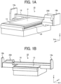
- FIGS. 1A and 1B are perspective views illustrating an example of the overall configuration of the image forming apparatus 10 according to the present embodiment.
- FIG. 1A is a perspective front view of the image forming apparatus 10
- FIG. 1B is a perspective rear view of the image forming apparatus 10.
- the image forming apparatus 10 includes a carriage 200 and a sheet table 13 on which a sheet P is placed.
- An ink discharge head e.g., a metallic ink discharge head 300 and color ink discharge heads 301a and 301b as illustrated in FIG. 2
- an irradiation unit 400 (see FIG. 2 ) are mounted on the carriage 200.
- the ink discharge head is an example of a liquid discharge head including a nozzle row in which a plurality of nozzles is arranged in the sub-scanning direction to discharge ink onto the sheet P.
- the ink discharge head discharges ink from the nozzles to form an image.
- the nozzles face the sheet table 13.
- the irradiation unit 400 also faces the sheet table 13.
- the ink discharge head and the irradiation unit 400 is described in detail later with reference to FIG. 2 .
- a guide rod 19 is bridged between left and right side plates 18a and 18b.
- the guide rod 19 movably holds the carriage 200 in the X-axis direction.
- the carriage 200 moves in the main scanning direction relative to the sheet P along the guide rod 19 (i.e., a main scanning movement).
- the carriage 200, the guide rod 19, and the side plates 18a and 18b are combined as a single body and movable together in the Y-axis direction along a guide rail 29 disposed below the sheet table 13.
- the carriage 200 moves in the sub-scanning direction relative to the recording medium along the guide rail 29 (i.e., a sub-scanning movement).
- the carriage 200 is movably held in the Z-axis direction (vertical direction).
- the image forming apparatus 10 performs one-way printing in which an image is formed while the carriage 200 moves forward, that is, in the main scanning movement in +X direction.
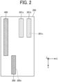
- FIG. 2 is a plan view illustrating an example of the configuration of the carriage 200.
- the carriage 200 illustrated in FIG. 1 is viewed in +Z direction.
- the carriage 200 has a box shape that is open in -Z direction.
- the carriage 200 includes, inside the box shape, the metallic ink discharge head 300, the color ink discharge heads 301a and 301b, and the irradiation unit 400.
- the color ink discharge heads 301a and 301b have the same configuration except for the color of ink to be discharged and the position where each of the color ink discharge heads 301a and 301b is disposed. Therefore, the color ink discharge heads 301a and 301b are collectively referred to as the color ink discharge heads 301, and each of the color ink discharge heads 301a and 301b is simply referred to as the color ink discharge head 301 unless otherwise distinguished.
- the metallic ink discharge head 300 also has the same configuration as the color ink discharge heads 301 except for the type of ink to be discharged and the position thereof, but do not necessarily have the same configuration.
- the carriage 200 holds the metallic ink discharge head 300, the color ink discharge heads 301, and the irradiation unit 400 each of which faces the sheet P placed below the carriage
- the metallic ink discharge head 300 includes a piezoelectric element as a pressure generator.
- the piezoelectric element is contracted in response to drive signals, thereby changing the pressure of the metallic ink in the metallic ink discharge head 300. Accordingly, the metallic ink is discharged in -Z direction through each nozzle included in a nozzle row 300n of the metallic ink discharge head 300.
- the metallic ink used in the present embodiment is an ultraviolet curable ink and includes at least a monomer or an oligomer, a photopolymerization initiator, and metallic particles.
- an ink containing a methacrylate monomer can be used as the ultraviolet curable ink.
- Methacrylate monomer has characteristics of relatively weak skin sensitization and large cure shrinkage.
- the ultraviolet curable ink may further include an additive. Examples of the additive includes a sensitizer, a dispersant, a leveling agent, or a polymerization inhibitor, and the additive can be appropriately selected.
- the metallic particles are made of aluminum and has a scaly or flat shape having an outer diameter of about 5 ⁇ m and a thickness of about 0.1 ⁇ m to 0.2 ⁇ m.
- the metallic particles are not limited thereto, and metal other than aluminum can be used as the material of the metallic particles.
- the shape of the metallic particles is not limited to be scaly or flat.
- the color ink discharge head 301 includes a piezoelectric element as a pressure generator.
- the piezoelectric element is contracted in response to drive signals, thereby changing the pressure of the color ink in the color ink discharge head 301. Accordingly, the color ink is discharged in -Z direction through each nozzle included in a nozzle row 301n of the color ink discharge head 301.
- the color ink used in the present embodiment is an ultraviolet curable ink and includes at least a monomer or an oligomer, a photopolymerization initiator, and colored particles.
- the colored particles are particles of a dye, a pigment, or the like.
- the colors of the colored particles are, for example, cyan, magenta, yellow, and black, but are not limited thereto, and can be appropriately selected according to the use of the image forming apparatus 10.
- the material of the ultraviolet curable ink is not particularly limited to the above, and various materials can be appropriately used according to the use of the image forming apparatus 10. The same applies to the viscosity and surface tension of the ink.
- At least one of the metallic ink and the color ink preferably includes a solvent to increase volatility and improve curing efficiency or drying efficiency.
- At least one of the metallic ink and the color ink preferably includes water from the viewpoint of environmental resistance.
- the irradiation unit 400 irradiates the metallic ink and the color ink on the sheet P with light.
- the irradiation unit 400 emits the ultraviolet rays to cure the metallic ink and the color ink on the sheet P.
- the cured metallic ink and color ink are adhered and fixed to the sheet P.
- an ultraviolet (UV) lamp can be used as the irradiation unit 400.
- the length of the irradiation unit 400 in the sub-scanning direction is preferably longer than each length of the metallic ink discharge head 300 and the color ink discharge heads 301 in the sub-scanning direction.
- the irradiation unit 400 can irradiate the entire ink discharged by the metallic ink discharge head 300 or the color ink discharge head 301 onto the sheet P in the sub-scanning direction with ultraviolet rays in one main scanning movement.
- the irradiation unit 400, the metallic ink discharge head 300, and the color ink discharge heads 301 are disposed in this order from the upstream side to the downstream side in a forward path of the main scanning movement in +X direction.
- the color ink discharge heads 301a and 301b are disposed side by side in the main scanning direction.
- the metallic ink discharge head 300 is disposed downstream from the color ink discharge heads 301 in +Y direction along the sub-scanning direction and shifted by twice a predetermined distance in the sub-scanning direction from the position where the color ink discharge heads 301 are disposed.
- the predetermined distance in the sub-scanning direction is substantially equal to the lengths of the nozzle rows 300n and 301n along the sub-scanning direction.
- the predetermined distance in the sub-scanning direction is referred to as a sub-scanning distance.
- the color ink discharge heads 301 and the irradiation unit 400 overlap each other in the sub-scanning direction, and the metallic ink discharge head 300 and the irradiation unit 400 do not overlap each other in the sub-scanning direction.
- the metallic ink discharge head 300 is disposed downstream from the irradiation unit 400 in +Y direction along the sub-scanning direction and shifted by the sub-scanning distance from the position where the irradiation unit 400 is disposed.
- FIG. 3 is a block diagram illustrating the configuration of hardware of the image forming apparatus 10.
- the image forming apparatus 10 includes a controller unit 3, sensors 4, a conveyance unit 100, the carriage 200, the metallic ink discharge head 300, the color ink discharge heads 301, the irradiation unit 400, and a maintenance unit 500.
- the controller unit 3 includes a unit control circuit 31, a memory 32, a central processing unit (CPU) 33, and an interface (I/F) 34.
- the I/F 34 connects the image forming apparatus 10 to a personal computer (PC) 26 as an external device.
- the image forming apparatus 10 and the PC 26 may be connected in any form, for example, via a network or directly connected by a communication cable.
- the CPU 33 uses the memory 32 as a working area to control an operation of each unit of the image forming apparatus 10 such as the conveyance unit 100, the carriage 200, the metallic ink discharge head 300, the color ink discharge heads 301, the irradiation unit 400, and the maintenance unit 500 via the unit control circuit 31. Specifically, the CPU 33 controls the operation of each unit based on image data received from the PC 26 and data detected by the sensors 4 to form an image on the sheet P.
- the sensors 4 includes various sensors provided in the image forming apparatus 10, for example, an encoder sensor that detects the position of the carriage 200 in the main scanning direction.
- a printer driver is installed in the PC 26. The printer driver generates image data to be transmitted to the image forming apparatus 10.
- the image data includes command data for operating the carriage 200 of the image forming apparatus 10 and pixel data related to an image to be formed.
- the conveyance unit 100 includes a conveyance mechanism to convey the sheet P.
- the conveyance unit 100 is an example of a moving unit that performs the main scanning movement in which the carriage 200 is moved relative to the sheet P in the main scanning direction and the sub-scanning movement in which the carriage 200 is moved relative to the sheet P in the sub-scanning direction.
- the conveyance unit 100 includes the guide rod 19, the guide rail 29, and the like.
- the maintenance unit 500 maintains and recovers the discharge function of the metallic ink discharge head 300 and the color ink discharge heads 301.
- the maintenance unit 500 further includes a cap that covers the nozzle surface of the metallic ink discharge head 300 and the color ink discharge heads 301 to protect the nozzles from drying when the image forming apparatus 10 does not form an image.
- the cap is a moisture-retentive cap having a function of simply covering the nozzle surface to protect the nozzle surface from drying.
- the cap may be a suction cap coupled to a suction pump. In addition to the function of the moisture-retentive cap, the suction cap sucks thickened ink from the metallic ink discharge head 300 and the color ink discharge heads 301 by the suction pump.
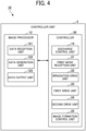
- FIG. 4 is a block diagram illustrating an example of the functional configuration of the controller unit 3.
- the controller unit 3 includes an image processor 12 and a controller 30.
- the image processor 12 includes a data reception unit 121, a data generation unit 122, and a data output unit 123.
- the data reception unit 121 receives image data from the PC 26.
- the image data includes information indicating a pattern and color of an image to be formed.
- the data generation unit 122 performs predetermined data processing such as color (cyan, magenta, yellow, and black) conversion processing, gradation reduction processing, and image conversion processing on the image data received by the data reception unit 121, and generates recording data for forming an image on the sheet P based on the image data.
- the data output unit 123 outputs the generated recording data to the controller 30.
- the controller 30 includes a discharge control unit 14, a print mode reception unit 21, an irradiation drive unit 22, a first drive unit 23, a second drive unit 24, and an image formation control unit 25.
- the discharge control unit 14 causes the metallic ink discharge head 300 and the color ink discharge head 301 to discharge ink based on the recording data.
- the print mode reception unit 21 receives data of a print mode.
- the print mode indicates color printing or monochrome printing, printing on one side or both sides of the sheet P, or the like.
- the irradiation drive unit 22 drives the irradiation unit 400 to emit ultraviolet rays.
- the first drive unit 23 causes the conveyance unit 100 to move the carriage 200 in the sub-scanning direction so as to move the carriage 200 and the sheet P relative to each other in the sub-scanning direction.
- the second drive unit 24 causes the conveyance unit 100 to move the carriage 200 in the main scanning direction so as to move the carriage 200 and the sheet P relative to each other in the main scanning direction.
- the image formation control unit 25 receives recording data from the image processor 12, and controls the discharge control unit 14, the irradiation drive unit 22, the first drive unit 23, and the second drive unit 24 to cause the metallic ink discharge head 300 and the color ink discharge heads 301 to discharge inks corresponding to each pixel of the recording data.
- FIG. 5 is a flowchart illustrating an example of the operation of the image forming apparatus 10.
- FIGS. 6A to 6E are plan views of the sheet P on which images are formed in first to fifth main scanning movements, respectively.
- FIG. 5 illustrates the operation triggered by a timing to start image formation control after the image forming apparatus 10 receives image data from the PC 26 and recording data is generated.
- FIG. 5 illustrates the operation when the image forming apparatus 10 forms an image in five main scanning movements, for example.
- step S51 the image formation control unit 25 moves the carriage 200 in the sub-scanning direction and stops the carriage 200 at an initial position for forming an image.
- step S52 the image formation control unit 25 drives a lift to move the carriage 200 to a height suitable for discharging ink by the metallic ink discharge head 300 and the color ink discharge head 301.
- the height means a position of the carriage 200 along the Z-axis direction. At this height, for example, a gap between the sheet P and, the metallic ink discharge head 300 and the color ink discharge head 301 is 1 mm.
- the image formation control unit 25 preferably drives the lift based on detection signals from a height sensor that detects the height of the metallic ink discharge head 300 and the color ink discharge head 301.
- step S53 the image formation control unit 25 moves the carriage 200 forward in the main scanning direction (i.e., +X direction), in other words, performs the first main scanning movement in +X direction.
- step S54 the metallic ink discharge head 300 discharges the metallic ink in a first region 61 of the sheet P as illustrated in FIG. 6A .
- the image formation control unit 25 stops the carriage 200, then moves the carriage 200 backward in the main scanning direction (i.e., -X direction), returns the carriage 200 to the original position in the main scanning direction, and stops the carriage 200.
- the metallic ink discharge head 300 and the color ink discharge head 301 do not discharge ink in the main scanning movement in -X direction (i.e., a backward path). Then, in step S55, the image formation control unit 25 moves the carriage 200 in the sub-scanning direction by the sub-scanning distance.
- step S56 the image formation control unit 25 moves the carriage 200 forward in the main scanning direction as a second main scanning movement.
- the metallic ink discharge head 300 discharges the metallic ink in a second region 62 of the sheet P as illustrated in FIG. 6B .
- the second region 62 is shifted by the sub-scanning distance downstream from the first region 61 in +Y direction along the sub-scanning direction.
- the irradiation unit 400 irradiates the metallic ink discharged in the first region 61 of the sheet P with ultraviolet rays. As a result, the metallic ink discharged in the first region 61 of the sheet P is cured and fixed onto the sheet P as illustrated in FIG. 6B .
- the irradiation unit 400 continuously turns on the UV lamp and continues emitting ultraviolet rays.
- the irradiation unit 400 faces the metallic ink and the color ink discharged in the first region 61 of the sheet P
- the irradiation unit 400 irradiates the metallic ink and the color ink with ultraviolet rays.
- the first region 61 and the irradiation unit 400 overlap each other in a direction in which the sheet P is viewed in plan view.
- the irradiation unit 400 may be controlled such that the UV lamp is turned on only when the irradiation unit 400 faces the metallic ink or the color ink discharged in the first region 61 of the sheet P, and the UV lamp is turned off in other times. The same applies to the subsequent irradiation of ultraviolet rays described later by the irradiation unit 400.
- the metallic ink discharge head 300 is disposed at a position shifted downstream from the irradiation unit 400 by the sub-scanning distance in +Y direction. Therefore, in the first main scanning movement, the irradiation unit 400 does not face the metallic ink discharged onto the sheet P in the first main scanning movement, and thus the metallic ink is not irradiated with ultraviolet rays. On the other hand, in the second main scanning movement, since the irradiation unit 400 faces the metallic ink discharged onto the sheet P in the first main scanning movement, the metallic ink is irradiated with ultraviolet rays. As a result, a long time is secured from the discharge of the metallic ink discharged onto the sheet P in the first main scanning movement to the start of curing the metallic ink.
- the image formation control unit 25 stops the carriage 200, then moves the carriage 200 backward in the main scanning direction (i.e., -X direction), returns the carriage 200 to the original position in the main scanning direction, and stops the carriage 200. Then, in step S59, the image formation control unit 25 moves the carriage 200 in the sub-scanning direction by the sub-scanning distance.
- step S60 the image formation control unit 25 moves the carriage 200 forward in the main scanning direction as a third main scanning movement.
- the color ink discharge head 301 discharges the color ink in the first region 61 of the sheet P.
- the metallic ink discharge head 300 discharges the metallic ink in a third region 63 of the sheet P as illustrated in FIG. 6C .
- the third region 63 is shifted by the sub-scanning distance downstream from the second region 62 in +Y direction along the sub-scanning direction.
- step S63 the irradiation unit 400 irradiates the metallic ink discharged in the second region 62 of the sheet P with ultraviolet rays.
- the irradiation unit 400 irradiates the color ink discharged in the first region 61 of the sheet P with ultraviolet rays.
- the metallic ink discharged in the second region 62 of the sheet P and the color ink discharged in the first region 61 of the sheet P are cured and fixed onto the sheet P as illustrated in FIG. 6C .
- the ink discharge head including the metallic ink discharge head 300 and the color ink discharge head 301 discharges the color ink in the first region 61 of the sheet P, in which the metallic ink has been discharged in the first main scanning movement, in the third main scanning movement after the first main scanning movement, and the irradiation unit 400 irradiates the first region 61 in which the color ink has been discharged with ultraviolet rays.
- the color ink discharge head 301 discharges the color ink in the third main scanning movement, and the irradiation unit 400 irradiates the region in which the color ink has been discharged with ultraviolet rays in the third main scanning movement which is the same main scanning movement in which the color ink is discharged.
- the first main scanning movement is an example of a former main scanning movement
- the third main scanning movement is an example of a latter main scanning movement performed after the former main scanning movement
- the second main scanning movement is an example of an intermediate main scanning movement performed after the former main scanning movement and before the latter main scanning movement. That is, the irradiation unit 400 irradiates the region, in which the metallic ink has been discharged in the former main scanning movement, of the sheet P with ultraviolet rays in the intermediate main scanning movement. Since the metallic ink discharged onto the sheet P in the second main scanning movement is irradiated with ultraviolet rays in the third main scanning movement, a long time is secured from the discharge of the metallic ink to the start of curing the metallic ink.
- the metallic ink discharge head 300 is disposed at a position shifted downstream from the color ink discharge head 301 by twice the sub-scanning distance in the sub-scanning direction. Therefore, in the third main scanning movement, the metallic ink discharge head 300 can discharge the metallic ink in the third region 63 of the sheet P, and the color ink discharge head 301 can discharge the color ink in the first region 61 of the sheet P. Further, since the color ink discharge head 301 and the irradiation unit 400 overlap each other in the sub-scanning direction, the color ink discharged onto the sheet P in the third main scanning movement is irradiated with ultraviolet rays in the same third main scanning movement.
- the image formation control unit 25 stops the carriage 200, then moves the carriage 200 backward in the main scanning direction (i.e., -X direction), returns the carriage 200 to the original position in the main scanning direction, and stops the carriage 200. Then, in step S64, the image formation control unit 25 moves the carriage 200 in the sub-scanning direction by the sub-scanning distance.
- step S65 the image formation control unit 25 moves the carriage 200 forward in the main scanning direction as a fourth main scanning movement.
- step S66 the color ink discharge head 301 discharges the color ink in the second region 62 of the sheet P.
- step S67 the irradiation unit 400 irradiates the metallic ink discharged in the third region 63 of the sheet P with ultraviolet rays. In parallel with this irradiation, the irradiation unit 400 irradiates the color ink discharged in the second region 62 of the sheet P with ultraviolet rays.
- the metallic ink discharged in the third region 63 of the sheet P and the color ink discharged in the second region 62 of the sheet P are cured and fixed onto the sheet P as illustrated in FIG. 6D .
- the color ink discharge head 301 discharges the color ink in the fourth main scanning movement, and the irradiation unit 400 irradiates the region in which the color ink has been discharged with ultraviolet rays in the same fourth main scanning movement in which the color ink is discharged.
- the image formation control unit 25 stops the carriage 200, then moves the carriage 200 backward in the main scanning direction (i.e., -X direction), returns the carriage 200 to the original position in the main scanning direction, and stops the carriage 200. Then, in step S68, the image formation control unit 25 moves the carriage 200 in the sub-scanning direction by the sub-scanning distance.
- step S69 the image formation control unit 25 moves the carriage 200 forward in the main scanning direction as a fifth main scanning movement.
- step S70 the color ink discharge head 301 discharges the color ink in the third region 63 of the sheet P.
- step S71 the irradiation unit 400 irradiates the color ink discharged in the third region 63 of the sheet P with ultraviolet rays. As a result, the color ink discharged in the third region 63 of the sheet P is cured and fixed onto the sheet P as illustrated in FIG. 6E .
- the image forming apparatus 10 can form images in the first to third regions 61 to 63 of the sheet P in the five main scanning movements.
- FIG. 5 and FIGS. 6A to 6D illustrate an operation of forming images in five main scanning movements
- the image forming apparatus 10 can repeat the operations of step S59 to step S63 in FIG. 5 to increase the number of main scanning movements.
- the image forming apparatus 10 can form an image in a larger area of the sheet P.
- the glossiness of the metallic ink is preferably improved.
- the ultraviolet curable ink is likely to be thick when forming an image, and the glossiness of the image may vary depending on the thickness of the ink. Therefore, there is room for improvement in the glossiness.
- the metallic ink is irradiated with light immediately after landing on a recording medium, the metallic ink is cured in a state immediately after landing on the recording medium.
- the metallic ink wets and spreads on the recording medium before being cured.
- the metallic ink is likely to be thin when forming an image, and a large number of metal foil pieces included in the metallic ink are likely to be oriented parallel to the recording medium.
- the image including a large number of metal foil pieces oriented parallel to the recording medium is likely to reflect light in the same direction without scattering the light, thereby improving the glossiness of the image.
- the image forming apparatus 10 includes the ink discharge head (liquid discharge head) that discharges ink (liquid) onto a sheet P (recording medium), the irradiation unit 400 that irradiates the ink on the sheet P with ultraviolet rays (light), and the carriage 200 on which the ink discharge head and the irradiation unit 400 are mounted.
- the image forming apparatus 10 further includes the conveyance unit 100 (moving unit) that alternately performs the main scanning movement in which the carriage 200 is moved relative to the sheet P in the main scanning direction and the sub-scanning movement in which the carriage 200 is moved relative to the sheet P in the sub-scanning direction perpendicular to the main scanning direction.
- the ink includes the metallic ink and the color ink. Further, the ink discharge head discharges the metallic ink in a region of the sheet P in the first main scanning movement (i.e., the former main scanning movement), and discharges the color ink in the region in which the metallic ink has been discharged, in the third main scanning movement (i.e., the latter main scanning movement) after the first main scanning movement. Thereafter, the irradiation unit 400 irradiates the region in which the color ink has been discharged with the light.
- the irradiation unit 400 irradiates the metallic ink with ultraviolet rays to cure the metallic ink in another main scanning movement after the main scanning movement in which the ink discharge head discharges the metallic ink. Accordingly, the time from the discharge of the metallic ink to the start of curing the metallic ink can be longer than the time from the discharge of the color ink to the start of curing the color ink. As a result, the glossiness of an image including the metallic ink is improved, and a colored and highly glossy image such as a metallic color image can be formed.
- a long time from the discharge of the metallic ink to the start of curing the metallic ink can be secured without moving the carriage 200 at a slow speed or stopping the carriage 200. Therefore, the high productivity of image formation can be secured while improving the glossiness of the image.
- the color ink discharge head 301 discharges the color ink in the third main scanning movement (i.e., the latter main scanning movement), and the irradiation unit 400 irradiates the region in which the color ink has been discharged with ultraviolet rays in the third main scanning movement which is the same main scanning movement in which the color ink is discharged.
- the time from the discharge of the metallic ink to the start of curing the metallic ink can be longer than the time from the discharge of the color ink to the start of curing the color ink, thereby improving the glossiness of an image including the metallic ink.
- the irradiation unit 400 irradiates each region of the sheet P in which the metallic ink has been discharged with ultraviolet rays twice in total, thereby reliably curing the metallic ink.
- the irradiation unit 400 may irradiate the region of the sheet P in which the color ink has been discharged with ultraviolet rays in another main scanning movement subsequent to the main scanning movement in which the color ink is discharged. Accordingly, the time from the discharge of the metallic ink to the second irradiation of ultraviolet rays can be even longer in each region of the sheet P, thereby further improving the glossiness of an image formed of the metallic ink. As a result, a colored and highly glossy image such as a metallic color image can be formed.
- the former main scanning movement may be any main scanning movement in an arbitrary order
- the latter main scanning movement may be another main scanning movement in an arbitrary order after the former main scanning movement.
- the former main scanning movement may be the second main scanning movement
- the latter main scanning movement may be the fourth main scanning movement after the former main scanning movement.
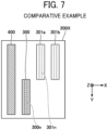
- FIG. 7 is a plan view of a carriage 200X according to a comparative example.
- components having similar functions to those of the carriage 200 according to the present embodiment are denoted by the same reference numerals for convenience.
- the color ink discharge head 301 and the irradiation unit 400 are overlap each other in the sub-scanning direction.
- the metallic ink discharge head 300 and the irradiation unit 400 are also overlap each other in the sub-scanning direction.
- the irradiation unit 400 irradiates the metallic ink discharged onto the sheet P with ultraviolet rays in the same main scanning movement in which the metallic ink discharge head 300 discharges the metallic ink.
- the metallic ink discharge head 300 since ultraviolet rays is emitted in another main scanning movement after the main scanning movement in which the metallic ink discharge head 300 discharges the metallic ink. Accordingly, the time from the discharge of the metallic ink to the start of curing the metallic ink can be longer than that of the comparative example. Therefore, in the present embodiment, the glossiness of the image including the metallic ink can be further improved as compared with the comparative example.
- ultraviolet curable ink a configuration in which ultraviolet curable ink is used has been described as an example, but is not limited thereto.
- an ink which is cured by light energy such as infrared rays or thermal energy may be used, but the ultraviolet curable ink is preferable from the viewpoint of curing efficiency.
- the metallic ink discharge head 300 and the color ink discharge head 301 are shifted from each other by twice the sub-scanning distance in the sub-scanning direction, but not limited thereto, for example, may be shifted by the integral multiple of the sub-scanning distance in the sub-scanning direction.
- the operation of the image forming apparatus that moves the carriage in both the main scanning direction and the sub-scanning direction has been described as an example, but not limited thereto.
- the carriage may be moved in the main scanning direction, and the sheet P may be moved in the sub-scanning direction.
- FIG. 8 is a perspective view illustrating another example of the configuration of such an image forming apparatus.
- an image forming apparatus 10a is viewed from obliquely above, and the interior thereof can be partially seen through the housing thereof.
- the image forming apparatus 10a includes an apparatus body 101, a feeding device 102, and a winding device 103.
- the feeding device 102 is a medium supply device that is disposed below the apparatus body 101 and supplies a sheet P wound in a roll shape.
- the sheet P wound in a roll shape is an example of a recording medium.
- a roll 112 that is the sheet P wound around a hollow shaft 115 is held in the feeding device 102.
- the winding device 103 includes a hollow shaft 114 for winding the sheet P.
- the sheet P is wound around the hollow shaft 114 as a roll 112.
- the feeding device 102 and the winding device 103 may be integrally formed with the apparatus body 101 instead of being separately formed.
- the feeding device 102 supplies the sheet P into the apparatus body 101.
- an image forming unit 104 forms an image on the sheet P supplied in a conveyance direction indicated by arrow B.
- the image forming unit 104 includes a guide rod 1 and a guide stay 2 as guides that are bridged between both side plates.
- the carriage 200 is supported by the guide rod 1 and the guide stay 2 so as to be movable in the main scanning direction indicated by arrow A.
- the winding device 103 winds the sheet P on which an image has been formed.
- a main scanning motor 8 as a driving source to reciprocate the carriage 200 is disposed on one side in the main scanning direction.
- the main scanning motor 8 rotates a drive pulley 9.
- a timing belt 11 is wound around the drive pulley 9 and a driven pulley 20 disposed on the other side in the main scanning direction.
- a belt holding portion of the carriage 200 is secured to the timing belt 11.
- the main scanning motor 8 is driven, the carriage 200 is reciprocated in the main scanning direction.
- the image forming apparatus 10a having such a configuration can obtain the same effect as that of the above-described image forming apparatus 10.
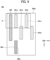
- FIG. 9 is a plan view of a carriage 200a of the image forming apparatus 10a according to the variation of the present embodiment.
- the image forming apparatus 10a differs from the above-described embodiment in that two sets of color ink discharge heads 301a and 301b are disposed along the sub-scanning direction in order to speed up color printing.
- a print mode reception unit 21 of the image forming apparatus 10a receives a print mode designated by a user or receives data of the print mode together with image data transmitted from the PC 26.
- the image forming apparatus 10a When the print mode received by the print mode reception unit 21 is a first image print mode including metallic color, the image forming apparatus 10a does not use one of the two sets of the color ink discharge heads 310a and 301b on the downstream side in +Y direction (adjacent to the metallic ink discharge head 300 in the sub-scanning direction) in FIG. 9 , and performs printing by discharging the metallic ink and the color ink substantially in the same manner as in the above-described embodiment. That is, the image forming apparatus 10a performs printing using only the color ink discharge heads 301a and 301b surrounded by a dashed square A in FIG. 9 for discharging the color ink.
- the image forming apparatus 10a performs printing using two sets of the color ink discharge heads 301a and 301b without using the metallic ink discharge head 300.
- the image forming apparatus 10a performs printing using two sets of the color ink discharge heads 301a and 301b, thereby printing an image at high speed.
- the image forming apparatus 10a can form a colored and highly glossy image such as a metallic color image. Other effects are the same as those of the image forming apparatus 10.
- the configuration in which the carriage 200 moves in both the main scanning direction and the sub-scanning direction and the configuration in which the carriage moves in the main scanning direction and the sheet P moves in the sub-scanning direction are described as examples, but the configuration is not limited thereto.
- a configuration in which the sheet P moves in both the main scanning direction and the sub-scanning direction or a configuration in which the sheet P moves in the main scanning direction and the carriage moves in the sub-scanning direction may be employed.
- the invention is defined in the claims.
- Embodiments also include an image forming method.
- An image forming method includes discharging a liquid onto a recording medium, irradiating the liquid on the recording medium with light, and alternately performing a main scanning movement and a sub-scanning movement.
- main scanning movement positions where the liquid is discharged and the light is emitted is moved relative to the recording medium in a main scanning direction.
- sub-scanning movement the positions where the liquid is discharged and the light is emitted is moved relative to the recording medium in a sub-scanning direction perpendicular to the main scanning direction.
- the liquid includes a metallic ink and a color ink.
- the image forming method further includes discharging the metallic ink in a region of the recording medium in a former main scanning movement, discharging the color ink in the region in which the metallic ink has been discharged, in a latter main scanning movement after the former main scanning movement, and irradiating the region in which the color ink has been discharged with the light.
- Such an image forming method may be implemented by a circuit such as a CPU or a large-scale integration (LSI), an integrated circuit (IC) card, a single module, or the like.
- LSI large-scale integration
- IC integrated circuit
- Embodiments also include a non-transitory recording medium storing program codes which, when executed by one or more processors, cause the one or more processors to perform the image forming method.
- a non-transitory recording medium stores program codes which, when executed by one or more processors, cause the one or more processors to perform an image forming method.
- the method includes discharging a liquid onto a recording medium, irradiating the liquid on the recording medium with light, and alternately performing a main scanning movement and a sub-scanning movement. In the main scanning movement, positions where the liquid is discharged and the light is emitted is moved relative to the recording medium in a main scanning direction.
- the positions where the liquid is discharged and the light is emitted is moved relative to the recording medium in a sub-scanning direction perpendicular to the main scanning direction.
- the liquid includes a metallic ink and a color ink.
- the image forming method further includes discharging the metallic ink in a region of the recording medium in a former main scanning movement, discharging the color ink in the region in which the metallic ink has been discharged, in a latter main scanning movement after the former main scanning movement, and irradiating the region in which the color ink has been discharged with the light.
- division of functional blocks illustrated in the block diagram is an example, and a plurality of blocks may be implemented as one block, one block may be divided into a plurality of blocks, or some functions may be transferred to another block. Further, functions of a plurality of blocks having similar functions may be processed in parallel or in time division by a single piece of hardware or software.
- the present invention can be implemented in any convenient form, for example using dedicated hardware, or a mixture of dedicated hardware and software.
- the present invention may be implemented as computer software implemented by one or more networked processing apparatuses.
- the processing apparatuses include any suitably programmed apparatuses such as a general purpose computer, a personal digital assistant, a Wireless Application Protocol (WAP) or third-generation (3G)-compliant mobile telephone, and so on. Since the present invention can be implemented as software, each and every aspect of the present invention thus encompasses computer software implementable on a programmable device.
- the computer software can be provided to the programmable device using any conventional carrier medium (carrier means).
- the carrier medium includes a transient carrier medium such as an electrical, optical, microwave, acoustic or radio frequency signal carrying the computer code.
- transient medium is a Transmission Control Protocol/Internet Protocol (TCP/IP) signal carrying computer code over an IP network, such as the Internet.
- the carrier medium may also include a storage medium for storing processor readable code such as a floppy disk, a hard disk, a compact disc read-only memory (CD-ROM), a magnetic tape device, or a solid state memory device.
Landscapes
- Health & Medical Sciences (AREA)
- General Health & Medical Sciences (AREA)
- Toxicology (AREA)
- Physics & Mathematics (AREA)
- Electromagnetism (AREA)
- Ink Jet (AREA)
Claims (7)
- Bilderzeugungsvorrichtung (10), die aufweist:einen Flüssigkeitsausstoßkopf (300; 301), der konfiguriert ist, um eine Flüssigkeit auf ein Aufzeichnungsmedium auszustoßen, wobei die Flüssigkeit eine metallische Tinte und eine Farbtinte enthält;eine Bestrahlungseinheit (400), die konfiguriert ist, um die Flüssigkeit auf dem Aufzeichnungsmedium mit Licht zu bestrahlen;einen Träger (200), auf welchem der Flüssigkeitsausstoßkopf (300; 301) und die Bestrahlungseinheit (400) montiert sind;eine Bewegungseinheit (100), die konfiguriert ist, um alternativ eine Hauptscanbewegung und eine Unterscanbewegung auszuführen, wobei bei der Hauptscanbewegung, in welche der Träger (200) bewegt wird, relativ zu dem Aufzeichnungsmedium in einer Hauptscanrichtung ist, wobei die Unterscanbewegung, in welche der Träger (200) bewegt wird, relativ zu dem Aufzeichnungsmedium in einer Unterscanrichtung senkrecht zu der Hauptscanrichtung ist, undeine Steuereinheit (3), die konfiguriert ist:um den Flüssigkeitsausstoßkopf (300) dazu zu veranlassen, die metallische Tinte in einem Bereich von dem Aufzeichnungsmedium in einer früheren Hauptscanbewegung auszustoßen;um den Flüssigkeitsausstoßkopf (301) dazu zu veranlassen, die Farbtinte in dem Bereich, in welchem die metallische Tinte ausgestoßen worden ist, bei einer letzteren Hauptscanbewegung nach der vorherigen Hauptscanbewegung auszustoßen; undum die Bestrahlungseinheit (400) dazu zu veranlassen, den Bereich mit dem Licht zu bestrahlen, in welchem die Farbtinte ausgestoßen worden ist,dadurch gekennzeichnet, dassdie Steuereinheit (3) ferner konfiguriert ist, um die Bestrahlungseinheit (400) dazu zu veranlassen, den Bereich, in welchem die Farbtinte ausgestoßen worden ist, mit dem Licht bei einer Zwischendurch-Hauptscanbewegung nach der vorherigen Hauptscanbewegung und vor der letzteren Hauptscanbewegung mit dem Licht zu bestrahlen.
- Bilderzeugungsvorrichtung (10) gemäß Anspruch 1,
wobei die Bestrahlungseinheit (400) den Bereich, in welchem die Farbtinte ausgestoßen worden ist, mit dem Licht bei der letzteren Hauptscanbewegung, bei welcher die Farbtinte ausgestoßen worden ist, bestrahlt. - Bilderzeugungsvorrichtung (10) gemäß Anspruch 1 oder 2,
wobei jede von der metallischen Tinte und der Farbtinte ultraviolett ausheizbar bzw. verfestigbar ist. - Bilderzeugungsvorrichtung (10) gemäß irgendeinem der Ansprüche 1 bis 3,
wobei zumindest eine von der metallischen Tinte und der Farbtinte ein Lösungsmittel enthält. - Bilderzeugungsvorrichtung (10) gemäß irgendeinem der Ansprüche 1 bis 3,
wobei zumindest eine von der metallischen Tinte und der Farbtinte Wasser enthält. - Bilderzeugungsverfahren, das aufweist:eine Flüssigkeit wird auf ein Aufzeichnungsmedium ausgestoßen (S54; S61), wobei die Flüssigkeit eine metallische Tinte und eine Farbtinte enthält;die Flüssigkeit wird auf dem Aufzeichnungsmedium mit Licht bestrahlt (S58; S63);aufeinanderfolgend werden eine Hauptscanbewegung und eine Unterscanbewegung durchgeführt (S53; S55), wobei die Hauptscanbewegung in deren Positionen, wo die Flüssigkeit ausgestoßen und das Licht abgestrahlt wird, relativ zu dem Aufzeichnungsmedium in einer Hauptscanrichtung bewegt wird, und wobei die Unterscanbewegung, in deren Positionen, wo die Flüssigkeit ausgestoßen und das Licht abgestrahlt wird, relativ zu dem Aufzeichnungsmedium in einer Unterscanrichtung senkrecht zu der Hauptscanrichtung bewegt wird;die metallische Tinte wird in einem Bereich des Aufzeichnungsmediums bei einer früheren Hauptscanbewegung ausgestoßen (S54);die Farbtinte wird in dem Bereich, in welchem die metallische Tinte ausgestoßen worden ist, bei einer letzteren Hauptscanbewegung nach der früheren Hauptscanbewegung ausgestoßen (S61); undder Bereich, in welchem die Farbtinte ausgestoßen worden ist, wird mit dem Licht bestrahlt (S63),dadurch gekennzeichnet, dassdas Verfahren ferner aufweist, dass der Bereich, in welchem die metallische Tinte ausgestoßen worden ist, mit dem Licht, bei einer Zwischendurch-Hauptscanbewegung nach der vorherigen bzw. früheren Hauptscanbewegung und vor der letzteren Hauptscanbewegung bestrahlt wird.
- Trägermedium, das einen computerlesbaren Code trägt, um ein Computersystem zu steuern, um das Bilderzeugungsverfahrens gemäß Anspruch 6 auszuführen.
Applications Claiming Priority (2)
| Application Number | Priority Date | Filing Date | Title |
|---|---|---|---|
| JP2021057705 | 2021-03-30 | ||
| JP2021211429A JP2022155472A (ja) | 2021-03-30 | 2021-12-24 | 画像形成装置、画像形成方法及び画像形成プログラム |
Publications (2)
| Publication Number | Publication Date |
|---|---|
| EP4067096A1 EP4067096A1 (de) | 2022-10-05 |
| EP4067096B1 true EP4067096B1 (de) | 2023-10-11 |
Family
ID=80786607
Family Applications (1)
| Application Number | Title | Priority Date | Filing Date |
|---|---|---|---|
| EP22162627.8A Active EP4067096B1 (de) | 2021-03-30 | 2022-03-17 | Bilderzeugungsgerät, bilderzeugungsverfahren und trägermedium |
Country Status (2)
| Country | Link |
|---|---|
| US (1) | US11999158B2 (de) |
| EP (1) | EP4067096B1 (de) |
Families Citing this family (1)
| Publication number | Priority date | Publication date | Assignee | Title |
|---|---|---|---|---|
| US12365187B2 (en) | 2022-03-23 | 2025-07-22 | Ricoh Company, Ltd. | Liquid application apparatus, liquid application method, and storage medium |
Family Cites Families (22)
| Publication number | Priority date | Publication date | Assignee | Title |
|---|---|---|---|---|
| JP4216153B2 (ja) | 2003-09-17 | 2009-01-28 | 株式会社リコー | ベルト搬送装置及びこれを用いた画像形成装置 |
| JP5233781B2 (ja) | 2008-09-02 | 2013-07-10 | 株式会社リコー | 液体容器及び画像形成装置 |
| JP5327617B2 (ja) | 2009-05-28 | 2013-10-30 | 株式会社リコー | 液体収容容器と液滴吐出装置及び画像形成装置 |
| JP5764868B2 (ja) * | 2010-03-10 | 2015-08-19 | セイコーエプソン株式会社 | 印刷装置及び印刷方法 |
| JP2011201151A (ja) * | 2010-03-25 | 2011-10-13 | Seiko Epson Corp | 印刷装置、印刷方法、印刷制御方法およびコンピュータープログラム |
| JP5702191B2 (ja) * | 2010-10-22 | 2015-04-15 | 株式会社ミマキエンジニアリング | インクジェット記録装置、及び印刷方法 |
| CN103402781B (zh) * | 2011-02-28 | 2015-04-29 | 富士胶片株式会社 | 喷墨记录方法及印刷物 |
| JP5653818B2 (ja) * | 2011-03-29 | 2015-01-14 | 富士フイルム株式会社 | インクジェット記録装置及び画像形成方法 |
| JP6188279B2 (ja) | 2012-04-27 | 2017-08-30 | 株式会社ミマキエンジニアリング | 印刷方法 |
| US8833892B2 (en) * | 2012-06-12 | 2014-09-16 | Seiko Epson Corporation | Printing apparatus and printing method |
| JP6461557B2 (ja) * | 2014-05-19 | 2019-01-30 | 株式会社ミマキエンジニアリング | 印刷装置及び印刷方法 |
| JP6246686B2 (ja) * | 2014-09-16 | 2017-12-13 | 富士フイルム株式会社 | インクジェット記録方法 |
| US10183504B2 (en) | 2015-01-05 | 2019-01-22 | Ricoh Company, Ltd. | Image processing device, image processing system, and method of forming image |
| JP6462374B2 (ja) * | 2015-01-22 | 2019-01-30 | 株式会社ミマキエンジニアリング | 印刷装置、及び印刷方法 |
| US10286688B2 (en) | 2017-01-25 | 2019-05-14 | Ricoh Company, Ltd. | Liquid discharge apparatus, liquid curing method, and computer program product |
| JP6985051B2 (ja) * | 2017-07-26 | 2021-12-22 | 株式会社ミマキエンジニアリング | 印刷方法、印刷装置、及び印刷システム |
| JP7115157B2 (ja) | 2017-10-06 | 2022-08-09 | 株式会社リコー | 吐出装置、画像形成装置、硬化方法およびプログラム |
| JP7081219B2 (ja) | 2018-03-05 | 2022-06-07 | 株式会社リコー | 液体吐出装置、及びプログラム |
| JP7043893B2 (ja) | 2018-03-06 | 2022-03-30 | 株式会社リコー | 液体を吐出する装置及び液体を吐出する方法 |
| JP7415431B2 (ja) | 2018-11-30 | 2024-01-17 | 株式会社リコー | 液体吐出装置、プログラムおよび吐出制御方法 |
| JP2021020401A (ja) | 2019-07-29 | 2021-02-18 | 株式会社リコー | 液体吐出装置、液体吐出方法、および液体吐出プログラム |
| JP7016994B2 (ja) * | 2019-09-11 | 2022-02-07 | ローランドディー.ジー.株式会社 | 印刷装置 |
-
2022
- 2022-03-17 EP EP22162627.8A patent/EP4067096B1/de active Active
- 2022-03-21 US US17/699,799 patent/US11999158B2/en active Active
Also Published As
| Publication number | Publication date |
|---|---|
| EP4067096A1 (de) | 2022-10-05 |
| US11999158B2 (en) | 2024-06-04 |
| US20220314657A1 (en) | 2022-10-06 |
Similar Documents
| Publication | Publication Date | Title |
|---|---|---|
| US10286688B2 (en) | Liquid discharge apparatus, liquid curing method, and computer program product | |
| CN113165381B (zh) | 液体喷射装置、程序和喷射控制方法 | |
| US10703113B2 (en) | Liquid discharge apparatus and method for discharging liquid | |
| US11230119B2 (en) | Liquid discharge apparatus, liquid discharge method, and non-transitory recording medium | |
| EP3976385B1 (de) | Flüssigkeitsausstossvorrichtung, flüssigkeitsausstossverfahren und aufzeichnungsmedium | |
| WO2003057488A1 (en) | Ink jet printer | |
| EP1627746B1 (de) | Druckvorrichtung mit Strahlungsquelle | |
| JP2004237588A (ja) | インクジェット記録装置 | |
| EP4067096A1 (de) | Bilderzeugungsgerät, bilderzeugungsverfahren und trägermedium | |
| JP4483265B2 (ja) | インクジェット記録装置 | |
| US11964467B2 (en) | Image forming apparatus, image forming method, and storage medium | |
| US12036785B2 (en) | Image forming apparatus, image forming method, and storage medium | |
| JP7172671B2 (ja) | 液体吐出装置及び制御方法 | |
| JP2012139655A (ja) | 印刷装置 | |
| JP2004167793A (ja) | インクジェットプリンタ | |
| CN111886137B (zh) | 液体排出装置及控制方法 | |
| JP3976736B2 (ja) | 紫外線硬化樹脂のコーティング装置 | |
| JP2022155472A (ja) | 画像形成装置、画像形成方法及び画像形成プログラム | |
| JP7793936B2 (ja) | 画像形成装置、画像形成方法及び画像形成プログラム | |
| JP2022155453A (ja) | 画像形成装置、画像形成方法及び画像形成プログラム | |
| US11772327B2 (en) | Device for fabricating solid freeform object and method of fabricating solid freeform object |
Legal Events
| Date | Code | Title | Description |
|---|---|---|---|
| PUAI | Public reference made under article 153(3) epc to a published international application that has entered the european phase |
Free format text: ORIGINAL CODE: 0009012 |
|
| STAA | Information on the status of an ep patent application or granted ep patent |
Free format text: STATUS: REQUEST FOR EXAMINATION WAS MADE |
|
| 17P | Request for examination filed |
Effective date: 20220317 |
|
| AK | Designated contracting states |
Kind code of ref document: A1 Designated state(s): AL AT BE BG CH CY CZ DE DK EE ES FI FR GB GR HR HU IE IS IT LI LT LU LV MC MK MT NL NO PL PT RO RS SE SI SK SM TR |
|
| GRAP | Despatch of communication of intention to grant a patent |
Free format text: ORIGINAL CODE: EPIDOSNIGR1 |
|
| STAA | Information on the status of an ep patent application or granted ep patent |
Free format text: STATUS: GRANT OF PATENT IS INTENDED |
|
| RIC1 | Information provided on ipc code assigned before grant |
Ipc: B41J 25/308 20060101ALN20230508BHEP Ipc: B41J 25/316 20060101ALI20230508BHEP Ipc: B41J 25/00 20060101ALI20230508BHEP Ipc: B41M 5/00 20060101ALI20230508BHEP Ipc: B41M 7/00 20060101ALI20230508BHEP Ipc: B41M 3/00 20060101ALI20230508BHEP Ipc: B41J 11/00 20060101AFI20230508BHEP |
|
| RIC1 | Information provided on ipc code assigned before grant |
Ipc: B41J 25/308 20060101ALN20230512BHEP Ipc: B41J 25/316 20060101ALI20230512BHEP Ipc: B41J 25/00 20060101ALI20230512BHEP Ipc: B41M 5/00 20060101ALI20230512BHEP Ipc: B41M 7/00 20060101ALI20230512BHEP Ipc: B41M 3/00 20060101ALI20230512BHEP Ipc: B41J 11/00 20060101AFI20230512BHEP |
|
| INTG | Intention to grant announced |
Effective date: 20230530 |
|
| GRAS | Grant fee paid |
Free format text: ORIGINAL CODE: EPIDOSNIGR3 |
|
| GRAA | (expected) grant |
Free format text: ORIGINAL CODE: 0009210 |
|
| STAA | Information on the status of an ep patent application or granted ep patent |
Free format text: STATUS: THE PATENT HAS BEEN GRANTED |
|
| P01 | Opt-out of the competence of the unified patent court (upc) registered |
Effective date: 20230828 |
|
| AK | Designated contracting states |
Kind code of ref document: B1 Designated state(s): AL AT BE BG CH CY CZ DE DK EE ES FI FR GB GR HR HU IE IS IT LI LT LU LV MC MK MT NL NO PL PT RO RS SE SI SK SM TR |
|
| REG | Reference to a national code |
Ref country code: GB Ref legal event code: FG4D |
|
| REG | Reference to a national code |
Ref country code: CH Ref legal event code: EP |
|
| REG | Reference to a national code |
Ref country code: DE Ref legal event code: R096 Ref document number: 602022000647 Country of ref document: DE |
|
| REG | Reference to a national code |
Ref country code: IE Ref legal event code: FG4D |
|
| REG | Reference to a national code |
Ref country code: LT Ref legal event code: MG9D |
|
| REG | Reference to a national code |
Ref country code: NL Ref legal event code: MP Effective date: 20231011 |
|
| REG | Reference to a national code |
Ref country code: AT Ref legal event code: MK05 Ref document number: 1619836 Country of ref document: AT Kind code of ref document: T Effective date: 20231011 |
|
| PG25 | Lapsed in a contracting state [announced via postgrant information from national office to epo] |
Ref country code: NL Free format text: LAPSE BECAUSE OF FAILURE TO SUBMIT A TRANSLATION OF THE DESCRIPTION OR TO PAY THE FEE WITHIN THE PRESCRIBED TIME-LIMIT Effective date: 20231011 |
|
| PG25 | Lapsed in a contracting state [announced via postgrant information from national office to epo] |
Ref country code: GR Free format text: LAPSE BECAUSE OF FAILURE TO SUBMIT A TRANSLATION OF THE DESCRIPTION OR TO PAY THE FEE WITHIN THE PRESCRIBED TIME-LIMIT Effective date: 20240112 |
|
| PG25 | Lapsed in a contracting state [announced via postgrant information from national office to epo] |
Ref country code: IS Free format text: LAPSE BECAUSE OF FAILURE TO SUBMIT A TRANSLATION OF THE DESCRIPTION OR TO PAY THE FEE WITHIN THE PRESCRIBED TIME-LIMIT Effective date: 20240211 |
|
| PG25 | Lapsed in a contracting state [announced via postgrant information from national office to epo] |
Ref country code: LT Free format text: LAPSE BECAUSE OF FAILURE TO SUBMIT A TRANSLATION OF THE DESCRIPTION OR TO PAY THE FEE WITHIN THE PRESCRIBED TIME-LIMIT Effective date: 20231011 |
|
| PG25 | Lapsed in a contracting state [announced via postgrant information from national office to epo] |
Ref country code: AT Free format text: LAPSE BECAUSE OF FAILURE TO SUBMIT A TRANSLATION OF THE DESCRIPTION OR TO PAY THE FEE WITHIN THE PRESCRIBED TIME-LIMIT Effective date: 20231011 |
|
| PG25 | Lapsed in a contracting state [announced via postgrant information from national office to epo] |
Ref country code: ES Free format text: LAPSE BECAUSE OF FAILURE TO SUBMIT A TRANSLATION OF THE DESCRIPTION OR TO PAY THE FEE WITHIN THE PRESCRIBED TIME-LIMIT Effective date: 20231011 |
|
| PG25 | Lapsed in a contracting state [announced via postgrant information from national office to epo] |
Ref country code: LT Free format text: LAPSE BECAUSE OF FAILURE TO SUBMIT A TRANSLATION OF THE DESCRIPTION OR TO PAY THE FEE WITHIN THE PRESCRIBED TIME-LIMIT Effective date: 20231011 Ref country code: IS Free format text: LAPSE BECAUSE OF FAILURE TO SUBMIT A TRANSLATION OF THE DESCRIPTION OR TO PAY THE FEE WITHIN THE PRESCRIBED TIME-LIMIT Effective date: 20240211 Ref country code: GR Free format text: LAPSE BECAUSE OF FAILURE TO SUBMIT A TRANSLATION OF THE DESCRIPTION OR TO PAY THE FEE WITHIN THE PRESCRIBED TIME-LIMIT Effective date: 20240112 Ref country code: ES Free format text: LAPSE BECAUSE OF FAILURE TO SUBMIT A TRANSLATION OF THE DESCRIPTION OR TO PAY THE FEE WITHIN THE PRESCRIBED TIME-LIMIT Effective date: 20231011 Ref country code: BG Free format text: LAPSE BECAUSE OF FAILURE TO SUBMIT A TRANSLATION OF THE DESCRIPTION OR TO PAY THE FEE WITHIN THE PRESCRIBED TIME-LIMIT Effective date: 20240111 Ref country code: AT Free format text: LAPSE BECAUSE OF FAILURE TO SUBMIT A TRANSLATION OF THE DESCRIPTION OR TO PAY THE FEE WITHIN THE PRESCRIBED TIME-LIMIT Effective date: 20231011 Ref country code: PT Free format text: LAPSE BECAUSE OF FAILURE TO SUBMIT A TRANSLATION OF THE DESCRIPTION OR TO PAY THE FEE WITHIN THE PRESCRIBED TIME-LIMIT Effective date: 20240212 |
|
| PG25 | Lapsed in a contracting state [announced via postgrant information from national office to epo] |
Ref country code: SE Free format text: LAPSE BECAUSE OF FAILURE TO SUBMIT A TRANSLATION OF THE DESCRIPTION OR TO PAY THE FEE WITHIN THE PRESCRIBED TIME-LIMIT Effective date: 20231011 Ref country code: RS Free format text: LAPSE BECAUSE OF FAILURE TO SUBMIT A TRANSLATION OF THE DESCRIPTION OR TO PAY THE FEE WITHIN THE PRESCRIBED TIME-LIMIT Effective date: 20231011 Ref country code: PL Free format text: LAPSE BECAUSE OF FAILURE TO SUBMIT A TRANSLATION OF THE DESCRIPTION OR TO PAY THE FEE WITHIN THE PRESCRIBED TIME-LIMIT Effective date: 20231011 Ref country code: NO Free format text: LAPSE BECAUSE OF FAILURE TO SUBMIT A TRANSLATION OF THE DESCRIPTION OR TO PAY THE FEE WITHIN THE PRESCRIBED TIME-LIMIT Effective date: 20240111 Ref country code: LV Free format text: LAPSE BECAUSE OF FAILURE TO SUBMIT A TRANSLATION OF THE DESCRIPTION OR TO PAY THE FEE WITHIN THE PRESCRIBED TIME-LIMIT Effective date: 20231011 Ref country code: HR Free format text: LAPSE BECAUSE OF FAILURE TO SUBMIT A TRANSLATION OF THE DESCRIPTION OR TO PAY THE FEE WITHIN THE PRESCRIBED TIME-LIMIT Effective date: 20231011 |
|
| PG25 | Lapsed in a contracting state [announced via postgrant information from national office to epo] |
Ref country code: DK Free format text: LAPSE BECAUSE OF FAILURE TO SUBMIT A TRANSLATION OF THE DESCRIPTION OR TO PAY THE FEE WITHIN THE PRESCRIBED TIME-LIMIT Effective date: 20231011 |
|
| REG | Reference to a national code |
Ref country code: DE Ref legal event code: R097 Ref document number: 602022000647 Country of ref document: DE |
|
| PG25 | Lapsed in a contracting state [announced via postgrant information from national office to epo] |
Ref country code: CZ Free format text: LAPSE BECAUSE OF FAILURE TO SUBMIT A TRANSLATION OF THE DESCRIPTION OR TO PAY THE FEE WITHIN THE PRESCRIBED TIME-LIMIT Effective date: 20231011 |
|
| PG25 | Lapsed in a contracting state [announced via postgrant information from national office to epo] |
Ref country code: SK Free format text: LAPSE BECAUSE OF FAILURE TO SUBMIT A TRANSLATION OF THE DESCRIPTION OR TO PAY THE FEE WITHIN THE PRESCRIBED TIME-LIMIT Effective date: 20231011 |
|
| PG25 | Lapsed in a contracting state [announced via postgrant information from national office to epo] |
Ref country code: SM Free format text: LAPSE BECAUSE OF FAILURE TO SUBMIT A TRANSLATION OF THE DESCRIPTION OR TO PAY THE FEE WITHIN THE PRESCRIBED TIME-LIMIT Effective date: 20231011 Ref country code: SK Free format text: LAPSE BECAUSE OF FAILURE TO SUBMIT A TRANSLATION OF THE DESCRIPTION OR TO PAY THE FEE WITHIN THE PRESCRIBED TIME-LIMIT Effective date: 20231011 Ref country code: RO Free format text: LAPSE BECAUSE OF FAILURE TO SUBMIT A TRANSLATION OF THE DESCRIPTION OR TO PAY THE FEE WITHIN THE PRESCRIBED TIME-LIMIT Effective date: 20231011 Ref country code: IT Free format text: LAPSE BECAUSE OF FAILURE TO SUBMIT A TRANSLATION OF THE DESCRIPTION OR TO PAY THE FEE WITHIN THE PRESCRIBED TIME-LIMIT Effective date: 20231011 Ref country code: EE Free format text: LAPSE BECAUSE OF FAILURE TO SUBMIT A TRANSLATION OF THE DESCRIPTION OR TO PAY THE FEE WITHIN THE PRESCRIBED TIME-LIMIT Effective date: 20231011 Ref country code: DK Free format text: LAPSE BECAUSE OF FAILURE TO SUBMIT A TRANSLATION OF THE DESCRIPTION OR TO PAY THE FEE WITHIN THE PRESCRIBED TIME-LIMIT Effective date: 20231011 Ref country code: CZ Free format text: LAPSE BECAUSE OF FAILURE TO SUBMIT A TRANSLATION OF THE DESCRIPTION OR TO PAY THE FEE WITHIN THE PRESCRIBED TIME-LIMIT Effective date: 20231011 |
|
| PLBE | No opposition filed within time limit |
Free format text: ORIGINAL CODE: 0009261 |
|
| STAA | Information on the status of an ep patent application or granted ep patent |
Free format text: STATUS: NO OPPOSITION FILED WITHIN TIME LIMIT |
|
| 26N | No opposition filed |
Effective date: 20240712 |
|
| PG25 | Lapsed in a contracting state [announced via postgrant information from national office to epo] |
Ref country code: SI Free format text: LAPSE BECAUSE OF FAILURE TO SUBMIT A TRANSLATION OF THE DESCRIPTION OR TO PAY THE FEE WITHIN THE PRESCRIBED TIME-LIMIT Effective date: 20231011 |
|
| PG25 | Lapsed in a contracting state [announced via postgrant information from national office to epo] |
Ref country code: SI Free format text: LAPSE BECAUSE OF FAILURE TO SUBMIT A TRANSLATION OF THE DESCRIPTION OR TO PAY THE FEE WITHIN THE PRESCRIBED TIME-LIMIT Effective date: 20231011 |
|
| PG25 | Lapsed in a contracting state [announced via postgrant information from national office to epo] |
Ref country code: LU Free format text: LAPSE BECAUSE OF NON-PAYMENT OF DUE FEES Effective date: 20240317 |
|
| PG25 | Lapsed in a contracting state [announced via postgrant information from national office to epo] |
Ref country code: MC Free format text: LAPSE BECAUSE OF FAILURE TO SUBMIT A TRANSLATION OF THE DESCRIPTION OR TO PAY THE FEE WITHIN THE PRESCRIBED TIME-LIMIT Effective date: 20231011 |
|
| PG25 | Lapsed in a contracting state [announced via postgrant information from national office to epo] |
Ref country code: MC Free format text: LAPSE BECAUSE OF FAILURE TO SUBMIT A TRANSLATION OF THE DESCRIPTION OR TO PAY THE FEE WITHIN THE PRESCRIBED TIME-LIMIT Effective date: 20231011 Ref country code: LU Free format text: LAPSE BECAUSE OF NON-PAYMENT OF DUE FEES Effective date: 20240317 |
|
| REG | Reference to a national code |
Ref country code: BE Ref legal event code: MM Effective date: 20240331 |
|
| PG25 | Lapsed in a contracting state [announced via postgrant information from national office to epo] |
Ref country code: BE Free format text: LAPSE BECAUSE OF NON-PAYMENT OF DUE FEES Effective date: 20240331 |
|
| PG25 | Lapsed in a contracting state [announced via postgrant information from national office to epo] |
Ref country code: IE Free format text: LAPSE BECAUSE OF NON-PAYMENT OF DUE FEES Effective date: 20240317 |
|
| PG25 | Lapsed in a contracting state [announced via postgrant information from national office to epo] |
Ref country code: IE Free format text: LAPSE BECAUSE OF NON-PAYMENT OF DUE FEES Effective date: 20240317 Ref country code: BE Free format text: LAPSE BECAUSE OF NON-PAYMENT OF DUE FEES Effective date: 20240331 |
|
| PG25 | Lapsed in a contracting state [announced via postgrant information from national office to epo] |
Ref country code: CY Free format text: LAPSE BECAUSE OF FAILURE TO SUBMIT A TRANSLATION OF THE DESCRIPTION OR TO PAY THE FEE WITHIN THE PRESCRIBED TIME-LIMIT; INVALID AB INITIO Effective date: 20220317 |
|
| PG25 | Lapsed in a contracting state [announced via postgrant information from national office to epo] |
Ref country code: FI Free format text: LAPSE BECAUSE OF FAILURE TO SUBMIT A TRANSLATION OF THE DESCRIPTION OR TO PAY THE FEE WITHIN THE PRESCRIBED TIME-LIMIT Effective date: 20231011 |
|
| REG | Reference to a national code |
Ref country code: CH Ref legal event code: H13 Free format text: ST27 STATUS EVENT CODE: U-0-0-H10-H13 (AS PROVIDED BY THE NATIONAL OFFICE) Effective date: 20251024 |
|
| PG25 | Lapsed in a contracting state [announced via postgrant information from national office to epo] |
Ref country code: TR Free format text: LAPSE BECAUSE OF FAILURE TO SUBMIT A TRANSLATION OF THE DESCRIPTION OR TO PAY THE FEE WITHIN THE PRESCRIBED TIME-LIMIT Effective date: 20231011 |
|
| PG25 | Lapsed in a contracting state [announced via postgrant information from national office to epo] |
Ref country code: CH Free format text: LAPSE BECAUSE OF NON-PAYMENT OF DUE FEES Effective date: 20250331 |
|
| PGFP | Annual fee paid to national office [announced via postgrant information from national office to epo] |
Ref country code: GB Payment date: 20260324 Year of fee payment: 5 |
|
| PGFP | Annual fee paid to national office [announced via postgrant information from national office to epo] |
Ref country code: DE Payment date: 20260319 Year of fee payment: 5 |
|
| PGFP | Annual fee paid to national office [announced via postgrant information from national office to epo] |
Ref country code: FR Payment date: 20260323 Year of fee payment: 5 |