EP4067202B1 - Procédé et agencement de localisation d'un véhicule guidé sur rails dans un réseau d'itinéraires après la mise en service du véhicule - Google Patents
Procédé et agencement de localisation d'un véhicule guidé sur rails dans un réseau d'itinéraires après la mise en service du véhicule Download PDFInfo
- Publication number
- EP4067202B1 EP4067202B1 EP21166402.4A EP21166402A EP4067202B1 EP 4067202 B1 EP4067202 B1 EP 4067202B1 EP 21166402 A EP21166402 A EP 21166402A EP 4067202 B1 EP4067202 B1 EP 4067202B1
- Authority
- EP
- European Patent Office
- Prior art keywords
- vehicle
- absolute
- optical marker
- image
- computer
- Prior art date
- Legal status (The legal status is an assumption and is not a legal conclusion. Google has not performed a legal analysis and makes no representation as to the accuracy of the status listed.)
- Active
Links
Images

Classifications
-
- B—PERFORMING OPERATIONS; TRANSPORTING
- B61—RAILWAYS
- B61L—GUIDING RAILWAY TRAFFIC; ENSURING THE SAFETY OF RAILWAY TRAFFIC
- B61L25/00—Recording or indicating positions or identities of vehicles or trains or setting of track apparatus
- B61L25/02—Indicating or recording positions or identities of vehicles or trains
- B61L25/025—Absolute localisation, e.g. providing geodetic coordinates
-
- B—PERFORMING OPERATIONS; TRANSPORTING
- B61—RAILWAYS
- B61L—GUIDING RAILWAY TRAFFIC; ENSURING THE SAFETY OF RAILWAY TRAFFIC
- B61L27/00—Central railway traffic control systems; Trackside control; Communication systems specially adapted therefor
- B61L27/50—Trackside diagnosis or maintenance, e.g. software upgrades
- B61L27/57—Trackside diagnosis or maintenance, e.g. software upgrades for vehicles or trains, e.g. trackside supervision of train conditions
Definitions
- the invention relates to a method for locating a rail-bound vehicle in a route network following commissioning of the vehicle.
- the invention also relates to an arrangement for locating a rail-bound vehicle in a route network following commissioning of the vehicle.
- the invention relates to a computer program product and a provision device for this computer program product, wherein the computer program product is equipped with program instructions for carrying out this method.
- the invention can be used in connection with a method for locating a rail vehicle that is automatically controlled by ATS (Automatic Train Supervision), in particular operated driverlessly, for example a rail vehicle controlled by a CBTC train control and train protection system, with an on-board train control device and trackside train protection devices as well as with a localization unit for detecting position values while the rail vehicle is traveling.
- ATS Automatic Train Supervision
- the on-board automatic train control device of a rail-bound vehicle which is integrated into an Automatic Train Control (ATC) monitoring system, always knows the exact position of the vehicle on the track.
- ATC Automatic Train Control
- the vehicles are also serviced and parked in depots.
- the vehicles are equipped with an on-board train protection device that secures the vehicles during normal operation and can trigger braking if safety limits are exceeded.
- Modern, radio-based systems also include a trackside device of the train protection system that safely tracks train movements using position reports received from the vehicles.
- CBTC Common-Based Train Control
- the vehicles (trains) and the train protection system should be switched off on the one hand to save energy.
- the vehicles should be able to start operating again as quickly as possible in the most comfortable and therefore unrestricted operating mode (for example CTC, Continuous Train Control, without a fixed speed limit of 25 km/h).
- CTC Continuous Train Control
- the train protection system on the vehicle is switched off, the reliably measured and stored vehicle position is lost.
- This reliable location must be established by a laborious, driver-operated slow drive using location markers (balises), and travel in mode without a fixed speed limit is only possible again after a while, typically after 250 m or 1 to 2 minutes.
- document EP 3415400 A1 describes a method and a system for determining a position of a guided vehicle within a rail network.
- the system comprises a camera installed on board the guided vehicle, a trackside plate installed along the track section, an identifier and at least one fixed-size feature, an identifier database storing a set of data for each identifier, and a processing unit.
- the processing unit is configured to calculate the position of the guided vehicle.
- the invention is based on the object of designing a method of the type specified at the outset in such a way that it can be used to quickly locate a rail vehicle with comparatively little effort. It is also the object of the invention to specify an arrangement, a computer program product and a provision device for such a device with which the method can be carried out. Finally, it is the object of the invention to specify an automatic train control system with which the above-mentioned method can be carried out.
- At least one camera is used for localization, which takes an image of the vehicle and of at least one stationary optical marker, the absolute position of which in the route network is known, a relative vehicle position of the vehicle to the stationary optical marker is determined in the image and the absolute vehicle position of the vehicle in the route network is determined taking into account the absolute position of the marker and the relative position of the vehicle.
- the method according to the invention advantageously makes it possible to immediately determine the position of a track-bound vehicle when it is put into operation, for example a local train such as a metro train in the depot.
- cameras are used which image stationary optical markers in the area surrounding the vehicle and the vehicle itself. Image processing can thus determine the relative position of the vehicle to the stationary optical marker. Since the stationary optical marker (the stationary and mobile optical markers are also referred to as markers below) cannot move, unlike the vehicle, the absolute position of the vehicle in the route network, for example in the depot, can also be determined using the relative position of the vehicle to the marker.
- the inventive localization of the vehicle is inherently subject to measurement errors.
- a localization normally provided for in the vehicle's operating procedure (known per se) must be carried out. This can be done, for example, by driving the vehicle over a beacon that is installed in the track (more on this below).
- the method according to the invention has the advantage that the vehicle can be provisionally located before it is put into operation. Therefore, costly locating devices, which would enable the vehicle to be located immediately and precisely, can be saved at the location where the method according to the invention is used (for example in a vehicle depot). On the other hand, the vehicle can be put into operation without the need for exclusively manual operation by a driver who has to board the train for this purpose. This would result in considerable savings in personnel costs, particularly in the case of driverless rail operations.
- CMD cold movement detection
- the method according to the invention can also be used if a CMD is provided for the vehicle. If the CMD fails, there is then an alternative way of detecting vehicle movement, so that manual driver operation can be dispensed with even if the CMD fails, because the method provides a second, independent way of localization.
- fixed devices are those that have constant coordinates in a global coordinate system (connected to the earth).
- mobile devices are understood to mean that the position of the mobile object (for example a vehicle or a vehicle-mounted mobile optical marker) can change.
- An absolute position is the position of an object (in particular a vehicle, a marker) in the global coordinate system.
- a relative position is the position of an object in relation to another object (for example, a vehicle in relation to a stationary optical marker).
- “computer-aided” or “computer-implemented” can be understood to mean an implementation of the method in which at least one computer carries out at least one method step of the method.
- Computers covers all electronic devices with data processing capabilities.
- Computers may include, for example, personal computers, servers, handheld computers, mobile phones and other communication devices, processors and other electronic devices for data processing that preferably also be connected to form a network.
- a "processor” can be understood as, for example, a converter, a sensor for generating measurement signals or an electronic circuit.
- a processor can in particular be a main processor (Central Processing Unit, CPU), a microprocessor, a microcontroller or a digital signal processor, possibly in combination with a memory unit for storing program instructions, etc.
- a processor can also be understood as a virtualized processor or a soft CPU.
- a “storage unit” can be understood as meaning, for example, a computer-readable memory in the form of a random access memory (RAM) or data storage device (hard disk or data carrier).
- RAM random access memory
- data storage device hard disk or data carrier
- Interfaces can be implemented in hardware terms, for example as a wired or wireless connection, or in software terms, for example as an interaction between individual program modules of one or more computer programs.
- Program modules are to be understood as individual functional sequences that enable a program sequence of computer-aided process steps according to the invention. These functional sequences can be implemented in a single computer program or in several computer programs that communicate with each other. The interfaces implemented here can be implemented in software within a single processor or in hardware if several processors are used.
- the method uses an output device for displaying the image and an input device for entering the absolute vehicle position.
- the output device is preferably a screen that displays the recorded image.
- the input device is, for example, a keyboard or a control panel specifically designed for the purpose of input.
- the method uses an output device for displaying the image and an input device for entering the relative vehicle position, and the absolute vehicle position in the route network is determined by computer, taking into account the absolute position of the stationary marker and the relative vehicle position.
- an employee can determine the relative position of the vehicle to preferably one of several fixed markers. These markers can, for example, be numbered in order to be able to provisionally determine the position of the vehicle in a depot.
- the input device can then be used by the employee to enter a specific position of the vehicle in the route network.
- the output device and the input device can also be used when the position of the vehicle is determined with a higher degree of automation.
- the operating personnel can take on the role of a control authority, since, as already mentioned, the location determination is less precise than would be the case in normal operation of the vehicle due to the ATC system used. This means that the operating personnel can intervene if obvious location errors occur.
- the relative vehicle position to the stationary marker in the image is determined by computer and the absolute vehicle position in the route network is determined by computer, taking into account the absolute position of the fixed marker and the relative vehicle position.
- Automated image interpretation advantageously increases the reproducibility of position determination.
- the measurement errors that occur can also be narrowed down more precisely than is the case with a human evaluation of the recorded image.
- malfunctions can occur that are not noticed in an automatic position calculation. Therefore, additional control by the operating personnel is advantageous, although this is supported by the automatic position determination.
- the absolute vehicle position is used as preliminary location information for commissioning the vehicle in a restricted operating mode and the preliminary location information is replaced by secure location information as soon as the vehicle has been detected by a locating device equipped with a security level, and the secure location information is used after a change from the restricted operating mode to a normal operating mode.
- the vehicle can also be put into operation if no vehicle position is yet known, which is usually used for the ATC system in operation.
- the vehicle Since there is greater uncertainty regarding the location information used than in normal operation of the vehicle, the vehicle is put into operation in a restricted operating mode, with restrictions designed to prevent operational disruptions and accidents.
- the at least one camera is used at least once more for localization, which camera takes an image of the vehicle and of at least one stationary optical marker whose absolute position in the route network is known, a relative vehicle position of the vehicle to the stationary optical marker is determined in the image, the absolute vehicle position of the vehicle in the route network is determined taking into account the absolute position of the marker and the relative position of the vehicle.
- the localization step can be designed in the manner already described above (i.e. as in the first measurement).
- the vehicle's ATC system can, for example, determine how the vehicle can reach the nearest tracking device as quickly as possible.
- the nearest tracking device can be on the adjacent track, but cannot be reached by the vehicle because the adjacent track is being used in the opposite direction, for example.
- the maximum permitted speed for example 25 km/h, which in the restricted operating mode is of course lower than that in the normal operating mode, and also the maximum permitted distance, which is preferably in an area of the route network separated from regular services, offer restrictions for the operating mode that can advantageously increase operational safety when using still inaccurate preliminary location information. Manual intervention by the train staff is also easier in this way.
- the at least one camera is also used to take an image of a mobile optical marker of the vehicle attached to the vehicle, the position of which on the vehicle is known.
- the use of a mobile optical marker on the vehicle makes it possible to determine its relative position to a
- the mobile optical marker is much smaller than the entire vehicle and its position relative to the stationary optical marker is therefore easier to determine.
- the determination of the absolute position is more accurate and the procedure is therefore safer.
- the stationary and/or mobile optical markers have a coding of alphanumeric characters and/or a machine-readable coding.
- alphanumeric character includes (at least) the letters of a given alphabet, as well as the ten digits from 0 to 9. In a broader sense, special characters (e.g. punctuation marks: period, comma, letters with diacritics, brackets, etc.) are also counted as alphanumeric characters.
- Alphanumeric characters advantageously facilitate manual determination or manual checking of computer-aided determinations of the absolute and relative positions of the vehicle.
- Alphanumeric support can be provided, for example, by numbering stationary optical markers in a depot or similar (and marking the markers with the numbers). Likewise, different vehicles can be given consecutive numbers on mobile optical markers. This makes it easier for operating personnel to orient themselves during manual assessment.
- a machine-readable code facilitates the computer-aided evaluation of the recorded images.
- the code can contain train numbers and location information of the relevant stationary or mobile marker.
- the stationary and/or mobile optical markers have a position mark.
- Position marks enable a more precise determination of the location of the relevant stationary or mobile optical marker. This allows more precise calculation or determination results to be achieved. Position marks can consist of crosses or circles, for example, and are smaller than the size of the optical marker and can therefore be located more precisely. They can also be colored to make them easier to recognize in poor lighting conditions.
- the stated object is also achieved according to the invention with the specified subject matter of the claim (arrangement) according to claim 12 in that the arrangement has: at least one stationary optical marker of the arrangement, the absolute position of which in the route network is known, at least one camera which is set up to take an image of the vehicle and of the stationary optical marker, a computer which is set up to determine, with the aid of a computer, a relative vehicle position of the vehicle to the stationary optical marker in the image and to determine the absolute vehicle position of the vehicle in the route network taking into account the absolute position of the stationary optical marker and the relative position of the vehicle.
- a provision device for storing and/or providing the computer program product.
- the provision device is, for example, a Storage unit that stores and/or provides the computer program product.
- the provision device is, for example, a network service, a computer system, a server system, in particular a distributed, for example cloud-based computer system and/or virtual computer system, which stores and/or provides the computer program product preferably in the form of a data stream.
- the provision takes place in the form of a program data block as a file, in particular as a download file, or as a data stream, in particular as a download data stream, of the computer program product.
- This provision can also take place, for example, as a partial download consisting of several parts.
- Such a computer program product is read into a system, for example, using the provision device, so that the method according to the invention is carried out on a computer.
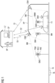
- a vehicle FZ is shown in a depot DP.
- the vehicle FZ is on a track GL, in which a balise BL is also installed outside the depot DP.
- control center LZ in which a computer CP is located can be recognized.
- the control center LZ is connected in a manner not shown in detail via a first interface S1 to a first camera CM1 in the depot DP, via a second interface S2 to a third camera CM3 and a fourth camera CM4 of the vehicle FZ and via a third interface S3 to a second camera CM2 outside the depot DP.
- the image angles BW of the first camera CM1, the second camera CM2 and the third camera CM3 are in Figure 1 indicated.
- a first stationary optical marker OM1 and a second stationary optical marker OM2 which are set up on the GL track and whose respective absolute position in the route network (represented by the GL track) is known.
- the vehicle FZ has a mobile optical marker OMM, which thus moves together with the vehicle.
- the second stationary optical marker OM2 has a position mark PSM in the form of a plus sign, which enables better localization of the second stationary optical marker OM2 on an image taken by the second camera CM2.
- the identification of this marker is made possible by a machine-readable code MLC (in Figure 1 shown as a barcode, but can also be executed as a QR code).
- MLC machine-readable code
- This information can be evaluated on the image recorded by the second camera CM2.
- an alphanumeric two is also provided as an alphanumeric character ANZ on the marker, which can be recognized on the image recorded by the second camera CM2, for example, by operating personnel.
- the first stationary optical marker OM1 is constructed in the same way. Of course, the barcode used there contains different information, and an alphanumeric one is used. Figure 1 the first stationary optical marker OM1 can be recorded both by the camera CM3 on the vehicle FZ and by the first camera CM1 permanently installed in the depot DP (see the indicated image angles BW).
- the mobile optical marker OMM on the vehicle FZ has a Z as an alphanumeric character so that the operating staff can perceive it as a train-related mobile optical marker.
- a barcode is used that contains the relevant information about the vehicle FZ.
- An Ix is used as a position marker
- an employee BP of the operating staff can evaluate the images taken by the cameras CM1, CM2, CM3 with the support of the computer CP in order to determine the position of the vehicle FZ in the depot DP before commissioning. Then, with the help of this Location information, the vehicle FZ can be put into operation in order to drive in a restricted operating mode to the balise BL and generate precise location information there by crossing the balise.
- the journey in the restricted operating mode and thus also the transition to the normal operating mode after crossing the balise can be carried out without a driver. Even in the normal operating mode, the vehicle FZ is preferably driven without a driver.
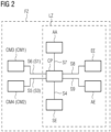
- Figure 2 the functional relationship of the individual components of the operating procedure is in accordance with Figure 1 In particular, it is shown how the computer CP supports the process.
- the computer CP as in Figure 1 shown, can be present in the control center LZ.
- an alternative is to carry out the procedure by the computer CP in the vehicle FZ. Therefore, in Figure 2
- the system boundaries when the computer CP is used in the control center LZ as well as when the computer CP is used in the vehicle FZ are indicated by dotted lines.
- the computing power of the computer CP can be distributed across several processors, which are distributed both in the control center LZ and in the vehicle FZ.
- we will speak of a computer CP in this case, the dotted system boundaries LZ, FZ would not exist).
- the computer CP is connected to a storage device SE via a fourth interface S4.
- the storage device SE can contain the software required to carry out the method, which is activated to carry out the method after, for example, the computer CP in the vehicle FZ has been started up.
- the storage device SE can also be used to store localization information calculated by the method.
- the computer CP is connected to the fourth camera CM4 via a fifth interface S5 and to the fourth camera CM4 via a sixth interface S6.
- third camera CM3. This applies when the computer CP is installed in the vehicle.
- the reference symbols in brackets apply in accordance with Figure 2 , that is, as in Figure 1
- the first camera CM1 is connected to the computer CP via the first interface S1
- the second camera CM2 is connected to the computer CP via the third interface S3.
- the computer CP is connected to an antenna arrangement AA, which enables communication via radio interfaces, for example between the control center LZ and the vehicle FZ, but also, for example, between the vehicle FZ and the balise BL (the antenna arrangement can have different antennas for this purpose).
- the computer CP is connected to an input unit EE via the eighth interface S8 and to an output unit AE via a ninth interface S9.
- the input unit EE enables inputs by the operating personnel in the manner already described, while the output device AE enables in particular the display of the images recorded by one of the cameras CM1 ... CM4.
- an activation step AKTV of the vehicle takes place.
- a subsequent image recording step PICT an image is taken by one of the cameras used.
- This can alternatively be output to the operating personnel via the ninth interface S9 using the output device AE in an output step OUT.
- This can estimate the relative position ESTM RPOS in a manual step and then use an input step IN using the eighth interface S8, enter the determined relative position into the computer CP.
- the relative position CALC RPOS the relative position of the vehicle to the marker depicted with the vehicle is calculated.
- the operating personnel can estimate the absolute position ESTM APOS of the vehicle manually and, in a subsequent input step IN, the absolute position APOS can be entered into the computer CP using the input device EE via the eighth interface S8. According to the invention, the absolute position APOS is also calculated by the computer CP in a calculation step CALC APOS.
- the absolute position APOS that is now available can be used to set the location information SET LOC in the next step. This is then available in the computer CP to start operation in the restricted operating mode MOD LIM of the vehicle. In this case, it is possible for the operating personnel to monitor operation in the restricted operating mode in a control step CRTL (for example by evaluating further images taken with the relevant cameras). This makes it possible for the operating personnel to intervene if there is a risk of operational disruptions or accidents.
- a query step REP? it is decided whether the localization procedure should be carried out again. This is useful if the operation in the restricted operating mode MOD LIM is aborted by the control step CRTL of the operating personnel or if there is a probability that repeating the localization (in the restricted operating mode) will improve the localization accuracy.
- the vehicle while operating in the restricted operating mode MOD LIM, reaches a locating device for a more precise localisation, which includes an absolute position acquisition step REC APOS which, due to a higher localization accuracy, subsequently enables the more precise location information SET LOC to be set again.
- a locating device for a more precise localisation which includes an absolute position acquisition step REC APOS which, due to a higher localization accuracy, subsequently enables the more precise location information SET LOC to be set again.
Landscapes
- Engineering & Computer Science (AREA)
- Mechanical Engineering (AREA)
- Health & Medical Sciences (AREA)
- Biomedical Technology (AREA)
- General Health & Medical Sciences (AREA)
- Train Traffic Observation, Control, And Security (AREA)
Claims (14)
- Procédé de localisation d'un véhicule (FZ) guidé sur rail dans un réseau de voies à la suite d'une mise en service du véhicule (FZ),
caractérisé en ce que
pour la localisation• on utilise au moins un appareil (CM1) photographique, qui prend une image du véhicule (FZ) et d'au moins un marqueur (OM1, OM2) optique fixe en position, dont la position absolue est connue dans le réseau de voies,• on détermine dans l'image une position relative du véhicule (FZ) par rapport au marqueur (OM1, OM2) optique fixe en position,• on détermine la position absolue du véhicule (FZ) dans le réseau de voies en tenant compte de la position absolue du marqueur et de la position relative du véhicule (FZ). - Procédé suivant la revendication 1
caractérisé en ce que l'
on utilise dans le procédé, un dispositif (AE) de sortie pour la représentation de l'image et un dispositif (EE) d'entrée pour l'entrée de la position absolue du véhicule. - Procédé suivant la revendication 1,
caractérisé en ce que• dans le procédé on utilise un dispositif (AE) de sortie pour la représentation de l'image et un dispositif (EE) d'entrée pour l'entrée de la position relative du véhicule,• on détermine d'une manière assistée par ordinateur la position absolue du véhicule dans le réseau de voies, en tenant compte de la position absolue du marqueur (OM1, OM2) optique fixe en position et de la position relative du véhicule. - Procédé suivant la revendication 1,
caractérisé en ce que l'• on détermine d'une manière assistée par ordinateur la position relative du véhicule par rapport au marqueur (OM1, OM2) fixe dans l'image,• on détermine d'une manière assistée par ordinateur la position absolue du véhicule dans le réseau de voies, en tenant compte de la position absolue du marqueur (OM1, OM2) fixe en position et de la position relative du véhicule. - Procédé suivant l'une des revendications précédentes, caractérisé en ce que l'• on utilise dans un mode (MOD LIM) de fonctionnement limité la position absolue du véhicule comme information de localisation provisoire pour une mise en service du véhicule (FZ), et• on remplace l'information de localisation provisoire par une information de localisation sûre, dès que le véhicule (FZ) a été détecté par un dispositif de localisation équipé d'un niveau de sécurité,• on utilise l'information de localisation sûre après un passage du mode (MOD LIM) de fonctionnement limité au mode (MOD NRM) de fonctionnement normal.
- Procédé suivant la revendication 5,
caractérisé en ce que
dans le mode de fonctionnement limité, au moins une fois pour la localisation• on utilise le au moins un appareil (CM1) photographique, qui prend une image du véhicule (FZ) d'au moins un marqueur (OM1, OM2) optique fixe en position, dont la position absolue dans le réseau de voies est connue,• on détermine dans l'image une position relative du véhicule (FZ) par rapport au marqueur optique fixe en position,• on détermine la position absolue du véhicule (FZ) dans le réseau de voies en tenant compte de la position absolue du marqueur optique fixe en position et de la position relative du véhicule (FZ). - Procédé suivant la revendication 5 ou 6,
caractérisé en ce que
dans le mode (MOD LIM) de fonctionnement limité, on met en marche le dispositif de localisation atteignable le plus proche. - Procédé suivant la revendication 5, 6 ou 7,
caractérisé en ce que l'
on limite le mode (MOD LIM) de fonctionnement limité à une vitesse maximum, qui peut être acquise dans le mode (MOD LIM) de fonctionnement limité, et/ou à une section maximum, qui peut être parcourue dans le mode (MOD LIM) de fonctionnement limité. - Procédé suivant l'une des revendications précédentes, caractérisé en ce que l'
on utilise également le au moins un appareil (CM1) photographique pour prendre une image d'un marqueur (OMM) optique mobile, monté sur le véhicule (FZ) et dont la position sur le véhicule (FZ) est connue. - Procédé suivant l'une des revendications précédentes, caractérisé en ce que
le marqueur optique à poste fixe (OM1, OM2) et/ou mobile (OMM) a un codage composé de signes (ANZ) alphanumériques et/ou un codage (MLC) déchiffrable par machine. - Procédé suivant l'une des revendications précédentes, caractérisé en ce que
les marqueurs optiques à poste fixe (OM1, OM2) et/ou mobiles (OMM) ont une marque (PSM) de position. - Agencement de localisation d'un véhicule (FZ) guidé sur rail dans un réseau de voies à la suite d'une mise en service du véhicule (FZ),
caractérisé en ce que
l'agencement comporte :• au moins un marqueur (OM1, OM2) optique à poste fixe de l'agencement, dont la position absolue dans le réseau de voies est connue,• au moins un appareil (CM1) photographique, qui est agencé pour prendre une image du véhicule (FZ) et du marqueur (OM1, OM2) optique à poste fixe,• un ordinateur (CP), qui est agencé pour déterminer dans l'image, d'une manière assistée par ordinateur, une position relative du véhicule (FZ) par rapport au marqueur optique à poste fixe et la position absolue du véhicule (FZ) dans le réseau de voies, en tenant compte de la position absolue du marqueur optique à poste fixe et de la position relative du véhicule (FZ). - Produit de programme d'ordinateur, comprenant des instructions de programme pour exécuter le procédé suivant l'une des revendications 1 à 11.
- Dispositif de mise à disposition du produit de programme d'ordinateur suivant la dernière revendication précédente, dans lequel le dispositif de mise à disposition met en mémoire le produit de programme d'ordinateur et/ou le met à disposition.
Priority Applications (3)
| Application Number | Priority Date | Filing Date | Title |
|---|---|---|---|
| EP21166402.4A EP4067202B1 (fr) | 2021-03-31 | 2021-03-31 | Procédé et agencement de localisation d'un véhicule guidé sur rails dans un réseau d'itinéraires après la mise en service du véhicule |
| ES21166402T ES3012357T3 (en) | 2021-03-31 | 2021-03-31 | Method and assembly for locating a track-bound vehicle in a route network following start-up of the vehicle |
| CN202210305623.4A CN115140124B (zh) | 2021-03-31 | 2022-03-25 | 在车辆起动后在路网中定位轨道导引的车辆的方法和装置 |
Applications Claiming Priority (1)
| Application Number | Priority Date | Filing Date | Title |
|---|---|---|---|
| EP21166402.4A EP4067202B1 (fr) | 2021-03-31 | 2021-03-31 | Procédé et agencement de localisation d'un véhicule guidé sur rails dans un réseau d'itinéraires après la mise en service du véhicule |
Publications (3)
| Publication Number | Publication Date |
|---|---|
| EP4067202A1 EP4067202A1 (fr) | 2022-10-05 |
| EP4067202C0 EP4067202C0 (fr) | 2024-11-20 |
| EP4067202B1 true EP4067202B1 (fr) | 2024-11-20 |
Family
ID=75339610
Family Applications (1)
| Application Number | Title | Priority Date | Filing Date |
|---|---|---|---|
| EP21166402.4A Active EP4067202B1 (fr) | 2021-03-31 | 2021-03-31 | Procédé et agencement de localisation d'un véhicule guidé sur rails dans un réseau d'itinéraires après la mise en service du véhicule |
Country Status (3)
| Country | Link |
|---|---|
| EP (1) | EP4067202B1 (fr) |
| CN (1) | CN115140124B (fr) |
| ES (1) | ES3012357T3 (fr) |
Families Citing this family (4)
| Publication number | Priority date | Publication date | Assignee | Title |
|---|---|---|---|---|
| DE102023210683A1 (de) * | 2023-10-27 | 2025-04-30 | Siemens Mobility GmbH | Positionsbestimmung eines Schienenfahrzeuges |
| EP4671084A1 (fr) | 2024-06-28 | 2025-12-31 | Siemens Mobility GmbH | Procédé de détermination de la vitesse d'un véhicule guidé se déplaçant sur un trajet |
| EP4671083A1 (fr) | 2024-06-28 | 2025-12-31 | Siemens Mobility GmbH | Procédé de localisation d'un véhicule guidé sur rails |
| EP4696583A1 (fr) | 2024-08-16 | 2026-02-18 | Siemens Mobility GmbH | Procédé de détermination de la vitesse d'un véhicule guidé se déplaçant sur un trajet |
Family Cites Families (11)
| Publication number | Priority date | Publication date | Assignee | Title |
|---|---|---|---|---|
| DE4012668A1 (de) * | 1990-04-20 | 1991-10-31 | W & M Engineering & Automation | Rocar-steuerung |
| KR101339354B1 (ko) * | 2012-03-26 | 2013-12-09 | 한국철도기술연구원 | 영상을 이용한 철도차량의 위치검지 시스템 및 위치검지방법 |
| DE102013218040A1 (de) | 2013-09-10 | 2015-03-12 | Siemens Aktiengesellschaft | Verfahren sowie Vorrichtung zum Erkennen einer Positionsänderung eines zumindest teilweisen abgeschalteten Fahrzeugs |
| CN103693078B (zh) * | 2013-12-18 | 2015-11-18 | 北京大成通号轨道交通设备有限公司 | 目标距离模式的列车自动防护方法 |
| DE102014212629A1 (de) * | 2014-06-30 | 2015-12-31 | Siemens Aktiengesellschaft | Verfahren zum Betreiben eines Schienenfahrzeugs |
| DE102014218761A1 (de) * | 2014-09-18 | 2016-03-24 | Siemens Aktiengesellschaft | Verfahren und Vorrichtung zur Stillstandsüberwachung |
| DE102014226045A1 (de) * | 2014-12-16 | 2016-06-16 | Siemens Aktiengesellschaft | Verfahren und Vorrichtung zur relativenZuglagenbestimmung zweier Züge |
| DE102015207223A1 (de) | 2015-04-21 | 2016-10-27 | Siemens Aktiengesellschaft | Verfahren und Anordnung zum Lokalisieren eines in einem CBTC (Communication-Based Train Control)-Zugsteuerungs- und Zugsicherungssystems verkehrenden Schienenfahrzeugs |
| WO2018104477A1 (fr) * | 2016-12-07 | 2018-06-14 | Siemens Aktiengesellschaft | Procédé, dispositif et véhicule sur voie, en particulier véhicule ferroviaire, pour la détection de voie en matière de trafic sur voie, en particulier pour la détection de voie ferrée en matière de trafic ferroviaire |
| EP3415400A1 (fr) * | 2017-06-12 | 2018-12-19 | Siemens Aktiengesellschaft | Système et procédé de mesure de la position d'un véhicule guidé |
| CN111914691B (zh) * | 2020-07-15 | 2024-03-19 | 北京埃福瑞科技有限公司 | 一种轨道交通车辆定位方法及系统 |
-
2021
- 2021-03-31 ES ES21166402T patent/ES3012357T3/es active Active
- 2021-03-31 EP EP21166402.4A patent/EP4067202B1/fr active Active
-
2022
- 2022-03-25 CN CN202210305623.4A patent/CN115140124B/zh active Active
Also Published As
| Publication number | Publication date |
|---|---|
| EP4067202A1 (fr) | 2022-10-05 |
| EP4067202C0 (fr) | 2024-11-20 |
| ES3012357T3 (en) | 2025-04-09 |
| CN115140124B (zh) | 2023-11-24 |
| CN115140124A (zh) | 2022-10-04 |
Similar Documents
| Publication | Publication Date | Title |
|---|---|---|
| EP4067202A1 (fr) | Procédé et agencement de localisation d'un véhicule guidé sur rails dans un réseau d'itinéraires après la mise en service du véhicule | |
| DE60300567T2 (de) | Zugregistrierungsüberlagerungssystem und -methode | |
| EP2250065B1 (fr) | Procédé de sécurisation de véhicules sur rails par des techniques de signalisation et système de sécurisation de ces véhicules | |
| WO2021121854A1 (fr) | Procédé et système de surveillance pour déterminer une position d'un véhicule ferroviaire | |
| EP2085287B1 (fr) | Procédé de détermination automatisée et réglage de paramètres d'alerte dans des véhicules sur rails et système correspondant | |
| DE19509696C2 (de) | Verfahren zur gegenseitigen Kontaktaufnahme zwischen Zügen und Einrichtung zur Durchführung des Verfahrens | |
| WO2018104477A1 (fr) | Procédé, dispositif et véhicule sur voie, en particulier véhicule ferroviaire, pour la détection de voie en matière de trafic sur voie, en particulier pour la détection de voie ferrée en matière de trafic ferroviaire | |
| DE69509398T2 (de) | Ein verkehrssteuerungssystem, dessen verwendung und ein bewegungssteuerungsverfahren einer mobilen einheit | |
| EP2531391A1 (fr) | Procédé et dispositif de contrôle de l'intégrité d'un train | |
| EP2121409B1 (fr) | Procédé, appareil de commande mobile et dispositif permettant de transmettre des données à un élément de parcours de transport guidé | |
| EP2870047B1 (fr) | Fonctionnement d'un véhicule ferroviaire | |
| DE102004057545A1 (de) | Verfahren zum automatischen Erkennen einer Zugtrennung | |
| EP3795451B1 (fr) | Procédé de localisation d'un véhicule dans une station destinée à un arrêt du véhicule | |
| DE102014212629A1 (de) | Verfahren zum Betreiben eines Schienenfahrzeugs | |
| EP1935749B1 (fr) | Procédé et système de localisation d'un véhicule sur rail | |
| EP1075996A1 (fr) | Procédé de localisation de véhicules dans un réseau de voies ferroviaires et véhicule ferroviaire | |
| AT413810B (de) | Einrichtung zur steuerung der fahrzeuge in einer gleisanlage | |
| DE102021117366A1 (de) | Verfahren zum Betreiben eines Zugbeeinflussungssystems | |
| AT525309A1 (de) | Verfahren zum sicheren Betreiben eines Schienenverkehrssystems und Schienenverkehrssystem | |
| DE102020206005A1 (de) | Fahrbetriebsanordnung und Verfahren zum Steuern eines Schienenfahrzeugs | |
| EP3458333B1 (fr) | Procédé et dispositif de détermination d'une longueur d'un véhicule guidé sur rails | |
| EP3738855A1 (fr) | Système de freinage commandé et d'arrêt dans une position définie pour un véhicule ferroviaire | |
| DE202022105203U1 (de) | Sichtbasierte Systeme zum Steuern von Inustriemaschinen und/oder zur Standortbestimmung | |
| DE19749697A1 (de) | Einrichtung zur Steuerung des Eisenbahnbetriebes | |
| DE2739231C3 (de) | Einrichtung zur Eigenortung spurgebundener Fahrzeuge |
Legal Events
| Date | Code | Title | Description |
|---|---|---|---|
| PUAI | Public reference made under article 153(3) epc to a published international application that has entered the european phase |
Free format text: ORIGINAL CODE: 0009012 |
|
| STAA | Information on the status of an ep patent application or granted ep patent |
Free format text: STATUS: THE APPLICATION HAS BEEN PUBLISHED |
|
| AK | Designated contracting states |
Kind code of ref document: A1 Designated state(s): AL AT BE BG CH CY CZ DE DK EE ES FI FR GB GR HR HU IE IS IT LI LT LU LV MC MK MT NL NO PL PT RO RS SE SI SK SM TR |
|
| STAA | Information on the status of an ep patent application or granted ep patent |
Free format text: STATUS: REQUEST FOR EXAMINATION WAS MADE |
|
| 17P | Request for examination filed |
Effective date: 20230403 |
|
| RBV | Designated contracting states (corrected) |
Designated state(s): AL AT BE BG CH CY CZ DE DK EE ES FI FR GB GR HR HU IE IS IT LI LT LU LV MC MK MT NL NO PL PT RO RS SE SI SK SM TR |
|
| GRAP | Despatch of communication of intention to grant a patent |
Free format text: ORIGINAL CODE: EPIDOSNIGR1 |
|
| STAA | Information on the status of an ep patent application or granted ep patent |
Free format text: STATUS: GRANT OF PATENT IS INTENDED |
|
| RIC1 | Information provided on ipc code assigned before grant |
Ipc: B61L 27/57 20220101ALI20240701BHEP Ipc: B61L 25/02 20060101AFI20240701BHEP |
|
| INTG | Intention to grant announced |
Effective date: 20240722 |
|
| GRAS | Grant fee paid |
Free format text: ORIGINAL CODE: EPIDOSNIGR3 |
|
| GRAA | (expected) grant |
Free format text: ORIGINAL CODE: 0009210 |
|
| STAA | Information on the status of an ep patent application or granted ep patent |
Free format text: STATUS: THE PATENT HAS BEEN GRANTED |
|
| AK | Designated contracting states |
Kind code of ref document: B1 Designated state(s): AL AT BE BG CH CY CZ DE DK EE ES FI FR GB GR HR HU IE IS IT LI LT LU LV MC MK MT NL NO PL PT RO RS SE SI SK SM TR |
|
| REG | Reference to a national code |
Ref country code: GB Ref legal event code: FG4D Free format text: NOT ENGLISH |
|
| REG | Reference to a national code |
Ref country code: CH Ref legal event code: EP |
|
| REG | Reference to a national code |
Ref country code: DE Ref legal event code: R096 Ref document number: 502021005838 Country of ref document: DE |
|
| REG | Reference to a national code |
Ref country code: IE Ref legal event code: FG4D Free format text: LANGUAGE OF EP DOCUMENT: GERMAN |
|
| U01 | Request for unitary effect filed |
Effective date: 20241203 |
|
| U07 | Unitary effect registered |
Designated state(s): AT BE BG DE DK EE FI FR IT LT LU LV MT NL PT RO SE SI Effective date: 20241212 |
|
| REG | Reference to a national code |
Ref country code: ES Ref legal event code: FG2A Ref document number: 3012357 Country of ref document: ES Kind code of ref document: T3 Effective date: 20250409 |
|
| PG25 | Lapsed in a contracting state [announced via postgrant information from national office to epo] |
Ref country code: IS Free format text: LAPSE BECAUSE OF FAILURE TO SUBMIT A TRANSLATION OF THE DESCRIPTION OR TO PAY THE FEE WITHIN THE PRESCRIBED TIME-LIMIT Effective date: 20250320 Ref country code: HR Free format text: LAPSE BECAUSE OF FAILURE TO SUBMIT A TRANSLATION OF THE DESCRIPTION OR TO PAY THE FEE WITHIN THE PRESCRIBED TIME-LIMIT Effective date: 20241120 |
|
| PG25 | Lapsed in a contracting state [announced via postgrant information from national office to epo] |
Ref country code: NO Free format text: LAPSE BECAUSE OF FAILURE TO SUBMIT A TRANSLATION OF THE DESCRIPTION OR TO PAY THE FEE WITHIN THE PRESCRIBED TIME-LIMIT Effective date: 20250220 |
|
| U20 | Renewal fee for the european patent with unitary effect paid |
Year of fee payment: 5 Effective date: 20250320 |
|
| PG25 | Lapsed in a contracting state [announced via postgrant information from national office to epo] |
Ref country code: GR Free format text: LAPSE BECAUSE OF FAILURE TO SUBMIT A TRANSLATION OF THE DESCRIPTION OR TO PAY THE FEE WITHIN THE PRESCRIBED TIME-LIMIT Effective date: 20250221 |
|
| PG25 | Lapsed in a contracting state [announced via postgrant information from national office to epo] |
Ref country code: PL Free format text: LAPSE BECAUSE OF FAILURE TO SUBMIT A TRANSLATION OF THE DESCRIPTION OR TO PAY THE FEE WITHIN THE PRESCRIBED TIME-LIMIT Effective date: 20241120 |
|
| PG25 | Lapsed in a contracting state [announced via postgrant information from national office to epo] |
Ref country code: RS Free format text: LAPSE BECAUSE OF FAILURE TO SUBMIT A TRANSLATION OF THE DESCRIPTION OR TO PAY THE FEE WITHIN THE PRESCRIBED TIME-LIMIT Effective date: 20250220 |
|
| PG25 | Lapsed in a contracting state [announced via postgrant information from national office to epo] |
Ref country code: SM Free format text: LAPSE BECAUSE OF FAILURE TO SUBMIT A TRANSLATION OF THE DESCRIPTION OR TO PAY THE FEE WITHIN THE PRESCRIBED TIME-LIMIT Effective date: 20241120 |
|
| PGFP | Annual fee paid to national office [announced via postgrant information from national office to epo] |
Ref country code: GB Payment date: 20250403 Year of fee payment: 5 Ref country code: ES Payment date: 20250620 Year of fee payment: 5 |
|
| PG25 | Lapsed in a contracting state [announced via postgrant information from national office to epo] |
Ref country code: SK Free format text: LAPSE BECAUSE OF FAILURE TO SUBMIT A TRANSLATION OF THE DESCRIPTION OR TO PAY THE FEE WITHIN THE PRESCRIBED TIME-LIMIT Effective date: 20241120 |
|
| PG25 | Lapsed in a contracting state [announced via postgrant information from national office to epo] |
Ref country code: CZ Free format text: LAPSE BECAUSE OF FAILURE TO SUBMIT A TRANSLATION OF THE DESCRIPTION OR TO PAY THE FEE WITHIN THE PRESCRIBED TIME-LIMIT Effective date: 20241120 |
|
| PLBE | No opposition filed within time limit |
Free format text: ORIGINAL CODE: 0009261 |
|
| STAA | Information on the status of an ep patent application or granted ep patent |
Free format text: STATUS: NO OPPOSITION FILED WITHIN TIME LIMIT |
|
| PG25 | Lapsed in a contracting state [announced via postgrant information from national office to epo] |
Ref country code: MC Free format text: LAPSE BECAUSE OF FAILURE TO SUBMIT A TRANSLATION OF THE DESCRIPTION OR TO PAY THE FEE WITHIN THE PRESCRIBED TIME-LIMIT Effective date: 20241120 |
|
| 26N | No opposition filed |
Effective date: 20250821 |
|
| REG | Reference to a national code |
Ref country code: CH Ref legal event code: H13 Free format text: ST27 STATUS EVENT CODE: U-0-0-H10-H13 (AS PROVIDED BY THE NATIONAL OFFICE) Effective date: 20251023 |
|
| U1H | Name or address of the proprietor changed after the registration of the unitary effect |
Owner name: SIEMENS MOBILITY GMBH; DE |
|
| PG25 | Lapsed in a contracting state [announced via postgrant information from national office to epo] |
Ref country code: CH Free format text: LAPSE BECAUSE OF NON-PAYMENT OF DUE FEES Effective date: 20250331 |
|
| PG25 | Lapsed in a contracting state [announced via postgrant information from national office to epo] |
Ref country code: IE Free format text: LAPSE BECAUSE OF NON-PAYMENT OF DUE FEES Effective date: 20250331 |
|
| U20 | Renewal fee for the european patent with unitary effect paid |
Year of fee payment: 6 Effective date: 20260320 |