EP4067593A1 - Einrichtung zur nachträglichen thermisch isolierenden, kraftübertragenden anbindung eines zweiten lastaufnehmenden bauwerksteils an ein erstes lastaufnehmendes bauwerksteil und bauwerk mit einer solchen einrichtung - Google Patents
Einrichtung zur nachträglichen thermisch isolierenden, kraftübertragenden anbindung eines zweiten lastaufnehmenden bauwerksteils an ein erstes lastaufnehmendes bauwerksteil und bauwerk mit einer solchen einrichtung Download PDFInfo
- Publication number
- EP4067593A1 EP4067593A1 EP22163162.5A EP22163162A EP4067593A1 EP 4067593 A1 EP4067593 A1 EP 4067593A1 EP 22163162 A EP22163162 A EP 22163162A EP 4067593 A1 EP4067593 A1 EP 4067593A1
- Authority
- EP
- European Patent Office
- Prior art keywords
- storage box
- tension rods
- longitudinal side
- load
- structural part
- Prior art date
- Legal status (The legal status is an assumption and is not a legal conclusion. Google has not performed a legal analysis and makes no representation as to the accuracy of the status listed.)
- Granted
Links
Images


Classifications
-
- E—FIXED CONSTRUCTIONS
- E04—BUILDING
- E04B—GENERAL BUILDING CONSTRUCTIONS; WALLS, e.g. PARTITIONS; ROOFS; FLOORS; CEILINGS; INSULATION OR OTHER PROTECTION OF BUILDINGS
- E04B1/00—Constructions in general; Structures which are not restricted either to walls, e.g. partitions, or floors or ceilings or roofs
- E04B1/003—Balconies; Decks
- E04B1/0038—Anchoring devices specially adapted therefor with means for preventing cold bridging
-
- E—FIXED CONSTRUCTIONS
- E04—BUILDING
- E04B—GENERAL BUILDING CONSTRUCTIONS; WALLS, e.g. PARTITIONS; ROOFS; FLOORS; CEILINGS; INSULATION OR OTHER PROTECTION OF BUILDINGS
- E04B1/00—Constructions in general; Structures which are not restricted either to walls, e.g. partitions, or floors or ceilings or roofs
- E04B1/62—Insulation or other protection; Elements or use of specified material therefor
- E04B1/74—Heat, sound or noise insulation, absorption, or reflection; Other building methods affording favourable thermal or acoustical conditions, e.g. accumulating of heat within walls
- E04B1/76—Heat, sound or noise insulation, absorption, or reflection; Other building methods affording favourable thermal or acoustical conditions, e.g. accumulating of heat within walls specifically with respect to heat only
- E04B1/78—Heat insulating elements
-
- E—FIXED CONSTRUCTIONS
- E04—BUILDING
- E04B—GENERAL BUILDING CONSTRUCTIONS; WALLS, e.g. PARTITIONS; ROOFS; FLOORS; CEILINGS; INSULATION OR OTHER PROTECTION OF BUILDINGS
- E04B5/00—Floors; Floor construction with regard to insulation; Connections specially adapted therefor
- E04B5/16—Load-carrying floor structures wholly or partly cast or similarly formed in situ
-
- E—FIXED CONSTRUCTIONS
- E04—BUILDING
- E04B—GENERAL BUILDING CONSTRUCTIONS; WALLS, e.g. PARTITIONS; ROOFS; FLOORS; CEILINGS; INSULATION OR OTHER PROTECTION OF BUILDINGS
- E04B1/00—Constructions in general; Structures which are not restricted either to walls, e.g. partitions, or floors or ceilings or roofs
- E04B1/62—Insulation or other protection; Elements or use of specified material therefor
- E04B1/74—Heat, sound or noise insulation, absorption, or reflection; Other building methods affording favourable thermal or acoustical conditions, e.g. accumulating of heat within walls
- E04B1/76—Heat, sound or noise insulation, absorption, or reflection; Other building methods affording favourable thermal or acoustical conditions, e.g. accumulating of heat within walls specifically with respect to heat only
- E04B2001/7679—Means preventing cold bridging at the junction of an exterior wall with an interior wall or a floor
Definitions
- the invention relates to a device for the subsequent thermally insulating, force-transmitting connection of a second load-bearing structure part to a first load-bearing structure part, in particular a building ceiling to a balcony slab, and a structure with such a device.
- a device for the subsequent connection of a prefabricated balcony to a building emerges.
- a recess is provided on the upper side of the balcony, in which the tension rods are connected to one another.
- the present invention is based on the object of creating a device for the subsequent thermally insulating, force-transmitting connection of a second load-bearing structure part to a first load-bearing structure part, which has an advantageous structure.
- a further object of the present invention consists in specifying a building with such a device.
- first tension rods protrude into the storage box on the first longitudinal side of the storage box
- second tension rods protrude into the storage box on the second longitudinal side
- the connecting device is arranged in the storage box. Due to the fact that the connecting device is arranged in the storage box, the connecting device can be easily protected from environmental influences by closing the storage box. At the same time, an attractive visual appearance is obtained since the connecting device is not visible from the outside after the storage box has been closed. A later filling of the area of the connecting device, for example with quick-hardening mortar or the like, can be omitted. This simplifies assembly on site.
- the arrangement of a recess in the first or the second part of the structure, in which the connecting device is arranged can be dispensed with. This avoids impairing the appearance of the first or second part of the structure.
- the tension rods protruding into the storage box on the first long side are advantageously provided for embedding in the first part of the building and the tension rods protruding into the storage box on the second long side are advantageously provided for embedding in the second part of the building.
- connection device Due to the arrangement of the connection device in the storage box, sufficient corrosion protection of the connection device and of the sections of the tension rods protruding into the storage box can be ensured in a simple manner. A supplementary corrosion protection can be omitted.
- the tension rods are intended to introduce forces into the concrete of the structural parts.
- the length of the tension rods required for this is calculated based on the forces to be transmitted. For the calculation of the length of the tie rods, only those sections of the tie rods that are well embedded in concrete of sufficient strength can be fully considered. If recesses are subsequently filled with sealing compound, the strength of the sealing compound and its connection to the tension rods can often not be guaranteed to a sufficient extent, so that tension rod sections running in the recesses cannot be included in the calculation or not to the same extent as tension rod sections that project into in-situ concrete or into concrete cast in the precast plant.
- the entire length of the tension rods lying outside of the storage box can be embedded in the first or second building part during the manufacture of the building parts and a recess does not have to be subsequently filled with sealing compound such as mortar the entire length of the tension rods running outside the storage box must be taken into account when calculating the required length of the tension rods, in particular when calculating the overlap length. As a result, a shorter length of the tension rods is required.
- the first tension rods and the second tension rods are advantageously arranged in a common plane running perpendicular to the vertical direction. As a result, a favorable introduction of force is achieved. At the same time, the connection of the tension rods in the storage box is possible in a simple manner, since no height offset between the tension rods has to be compensated.
- the connecting device particularly advantageously comprises a connecting plate which is arranged in the storage box and on which the first tension rods and the second tension rods are fixed.
- the connection plate is on a Arranged longitudinal side of the storage box in the storage box.
- the connecting plate is particularly advantageously arranged on the longitudinal side of the storage box that is closer to the balcony plate.
- the tie rods embedded in the building and protruding through the long side of the storage box remote from the balcony slab are preferably firmly connected to the connecting slab, for example by means of welded joints.
- the tension rods of the balcony slab are preferably pushed through openings in the connecting slab and fixed using screw connections, preferably using nuts.
- the connecting device advantageously includes at least one screw connection.
- the openings of the connecting plate are advantageously dimensioned so large that a tolerance compensation between the tie rods of the building and the tie rods of the balcony slab is possible.
- the storage box has at least one closable access opening, via which the connecting device is accessible.
- the access opening is particularly preferably designed to be resealable, so that the connecting device is accessible again after assembly by opening the storage box again.
- the access opening extends over the entire length and the entire width of the storage box. However, it can also be provided that the access opening only extends over the area of the storage box that covers the connecting device. In an alternative design, the access opening may only extend over the area of the threaded connections. Provision can also be made for the storage box to have a plurality of access openings, via which one or more threaded connections are accessible in each case.
- the storage box is preferably filled with mineral wool as insulating material.
- the insulating material is advantageously at least partially introduced after the first and second tension rods have been connected to one another in the storage box.
- a simple one Design results when the storage box is made of plastic.
- the storage box is particularly preferably made from extruded profiles. This enables the storage box to be produced simply and economically.
- the storage box preferably has a base body and at least one cover that can be connected to the base body.
- the cover is preferably detachably connected to the base body.
- the cover can be connected to the base body, for example, via a snap connection, latching or clamping.
- a different type of connection between the cover and the base body can also be advantageous.
- provision can be made for the cover to be permanently connected to the base body, for example by means of an adhesive connection.
- the storage box can be open at its end faces perpendicular to the longitudinal direction. This is particularly advantageous when several storage boxes are arranged next to one another on the front side. In particular for storage boxes that close the insulating joint in the longitudinal direction, it is advantageously provided that the storage box is closed on at least one end face. A further cover can be provided for this purpose.
- the storage box is advantageously designed to be closed in the transverse direction and in the vertical direction.
- At least one support for the vertical support of the second part of the structure is advantageously arranged on the second longitudinal side of the storage box.
- At least one transverse force bar advantageously protrudes through the storage box.
- the at least one transverse force bar is fixed to the support for the vertical support of the second part of the structure.
- a different connection of the shear force bar can also be advantageous.
- the structure has a first load-bearing structure part made of concrete and a second load-bearing structure part made of concrete as well as a device for connecting the second load-bearing structure part to the first load-bearing structure part.
- the device advantageously has two units that can be connected to one another, namely a unit to be fixed to the first building part and a unit to be fixed to the second building part, which can be connected to one another after the building parts have been produced.
- First tension rods are preferably embedded in the first structural part and second tension rods in the second structural part.
- the insulating body is preferably fixed to the first part of the structure. By connecting the tension rods to one another, the second part of the structure can be fixed to the first part of the structure.
- the building 50 has a first building part 2, in the exemplary embodiment a building ceiling, and a second building part 3, in the exemplary embodiment a balcony slab.
- the second structural part 3 is connected to the first structural part 2 via a thermally insulating component 1 in a thermally insulating and force-transmitting manner.
- the load-bearing parts of the structure 2 and 3 are made of concrete, in the exemplary embodiment made of steel-reinforced concrete.
- the load-bearing structural part 3 has been fixed to the first load-bearing structural part 2 after it has been produced.
- the load-bearing structural part 3 can be produced with high quality, for example in the prefabricated parts factory, and can be fixed very quickly to the structural part 2 on the construction site, which shortens crane times and thereby reduces production costs.
- the second building part 3 can, for example, be a balcony manufactured as a finished part.
- the thermally insulating component 1 comprises an insulating body 5 which is arranged in a parting line 4 between the first structural part 2 and the second structural part 3 .
- the insulator 5 has a first longitudinal side 6 on the first Building part 2 is arranged.
- the second, opposite longitudinal side 7 runs adjacent to the second structural part 3.
- a narrow gap is formed between the insulating body 5 and the second structural part 3.
- the second structural part 3 bears against the insulating body 5 .
- the insulating body 5 has a storage box 33 which is filled with insulating material 32 .
- the storage box 33 is advantageously made of plastic.
- the storage box 33 is made in particular from one or more extruded plastic profiles.
- the insulating material 32 is preferably mineral wool. However, another insulating material can also be provided.
- the storage box 33 is advantageously closed on its longitudinal sides 6 and 7 .
- one or more storage boxes 33 extend over the entire length of the expansion joint 4.
- Adjacent storage boxes 33 are advantageously arranged in such a way that their end faces 34 adjoin one another or—if the parting line 4 is angled—that an end face 34 of a storage box 33 adjoins a longitudinal side 6 of an adjacent storage box 33 is adjacent.
- the end faces 34 of the storage box 33 are also in the Figures 7 and 8 shown.
- the storage box 33 has a longitudinal direction 28 which is aligned in the longitudinal direction of the expansion joint 4 .
- the longitudinal direction 28 preferably runs horizontally in the installed state.
- the end faces 34 run transversely, in particular perpendicularly, to the longitudinal direction 28.
- the storage box 33 has a vertical direction 30, such as 1 shows, which runs perpendicular to the longitudinal direction 28.
- the vertical direction 30 preferably runs vertically in the installed state.
- the storage box 33 has a 1 shown transverse direction 29, which runs from the first longitudinal side 6 to the opposite longitudinal side 7.
- the transverse direction 29 is aligned perpendicularly to the longitudinal direction 28 and perpendicularly to the vertical direction 30 .
- the transverse direction 29 preferably runs horizontally in the installed state.
- the storage box 33 has an underside 8 oriented in the longitudinal direction 28 and connecting the long sides 6 and 7 and an upper side 47 oriented in the longitudinal direction 28 and connecting the long sides 6 and 7 .
- the top 47 is arranged above the bottom 8 in the installed state.
- the storage box 33 is advantageously closed on the upper side 47 and the lower side 8 .
- the storage box 33 can be designed to be open or closed on the end faces 34 running transversely to the longitudinal direction 28 .
- the thermally insulating component 1 together with other elements, forms a device for the force-transmitting connection of the second building part 3 to the first building part 2.
- the device consists of the thermally insulating component 1, which is fixed to the first building part 2, and other means arranged on the second building part 3 for power transmission.
- the force transmission means arranged on the second structure part 3 are advantageously detachably connected to the force transmission means arranged in the first structure part 2 . As a result, subsequent connection of the second structural part 3 to the first structural part 2 is possible.
- the device For the transmission of tensile forces between the structural parts 2 and 3, the device comprises first tension rods 9, which are embedded in the first structural part 2, and second tension rods 10, which are embedded in the second structural part 3.
- the tension rods 9 and 10 are connected to one another in a force-transmitting manner via a connecting device 35 .
- the connecting device 35 is arranged in the storage box 33 .
- the first tension rods 9 protrude through the first longitudinal side 6 into the storage box 33.
- the second tension rods 10 protrude through the second longitudinal side 7 into the storage box 33.
- the connecting device 35 comprises a connecting plate 11.
- the first tension rods 9 are firmly connected to the connecting plate 11, in the exemplary embodiment via welded connections 15 ( 2 ).
- the connecting plate 11 is in the storage box 33 on the inside of the second longitudinal side 7 arranged. This results in a space-saving arrangement and screw connections 40 of the second tension rods 10 are easily accessible.
- the second tension rods 10 are screwed to the connecting plate 11 .
- the connection plate 11 has openings 36 ( 1 ) through which the second tension rods 10 protrude into the interior of the storage box 33 .
- the second tension rods 10 have threaded sections 41 at their ends protruding into the storage box 33.
- the threaded sections 41 form screw connections 40 with fastening nuts 14 screwed onto the threaded sections 41.
- the second tension rods 10 are connected to the connecting plate 11 via the screw connections 40.
- a fastening nut 14 is screwed onto a threaded section 41 of each tension rod 10 on the side of the connecting plate 11 which is arranged away from the second longitudinal side 7 .
- a disk 21 is arranged between the fastening nuts 14 and the connecting plate 11 .
- the first tie rods 9 and the second tie rods 10 protrude from the connecting plate 11 on opposite sides.
- the tension rods 9 and 10 end in the interior of the storage box 33.
- both the first tension rods 9 and the second tension rods 10 are connected to the connecting plate 11 via screw connections 40 .
- Another force-transmitting connection of the tension rods 9 and 10 can also be advantageous.
- the connecting device 35 is designed in such a way that the tension rods 9 and 10 can be connected to one another after the building parts 2 and 3 have been produced.
- a support 17 is arranged on the second structural part 2 for the transmission of pressure forces and transverse forces.
- the support 17 is designed as a support bracket in the exemplary embodiment.
- the support 17 advantageously forms part of the thermally insulating component 1 and is in particular held captive on the storage box 33 .
- the support 17 is firmly connected to transverse force bars 16 .
- the transverse force bars 16 are in embedded in the concrete of the first structural part 2 and thereby connected to the first structural part 2 in a force-transmitting manner.
- the support 17 is supported in the horizontal direction on at least one first pressure rod 19 embedded in the first structural part 2 .
- the first pressure rod 19 extends from the second longitudinal side 7 through the first longitudinal side 6 of the storage box 33 into the first structural part 2.
- the first pressure rod 19 forms a pressure element.
- a different design of the pressure element can also be advantageous. It can be provided that the support 17 is firmly connected to the at least one compression bar 19 .
- a support bracket 31 is embedded in the second structural part 3 and rests on the support 17 . Pressure forces acting in the horizontal direction as well as transverse forces acting in the vertical direction are introduced into the support 17 from the second structural part 3 via the support angle 31 .
- the support bracket 31 is connected to at least one second pressure rod 20 .
- the at least one second pressure rod 20 is embedded in the second structural part 3 . A different type of pressure force introduction into the second part of the structure can also be advantageous.
- the first tension rods 9 have longitudinal axes 12 and the second tension rods 10 have longitudinal axes 13, as in FIG 2 is shown.
- the longitudinal axes 12 and 13 lie in a common, horizontal plane 38.
- the plane 38 runs parallel to the longitudinal direction 28 and parallel to the transverse direction 29.
- the plane 38 runs perpendicular to the vertical direction 30.
- the tension rods 9 and 10 are offset from one another in the plane 38 arranged.
- the longitudinal axes 12 and 13 of adjacent tension rods 9 and 10 in the exemplary embodiment have an offset a relative to one another, measured in the longitudinal direction 28 .
- the underside 8 of the storage box 33 runs approximately in one plane with an underside 45 of the support 17 and an underside 46 of the second structural part 3.
- the Figures 3 to 6 show the design of the storage box 33 in detail.
- the storage box 33 is formed by a base body 42 and a cover 43 .
- the cover 43 is shown removed.
- the cover 43 can be placed on the base body 42 in the direction of the arrow 48 and connected to it.
- an access opening 44 is open.
- the connecting device 35 is accessible from outside the storage box 33 via the access opening 44 .
- the second tension rods 10 can be pushed through openings in the connecting plate 11 and then fixed using the fastening nuts 14 .
- the fastening nuts 14 are accessible through the access opening 44 from the outside.
- the base body 42 can be filled with insulating material, preferably with mineral wool, and the cover 43 can then be put on and fixed.
- the cover 43 can be fixed to the base body 42 in particular via a detachable connection, for example via a snap connection, a clamp connection or a latching connection.
- the detachable connection is advantageously designed in such a way that the cover 43 can be removed again without being destroyed.
- a different connection of cover 43 and base body 42 can also be provided, for example an adhesive connection.
- a formwork body 37 is arranged on the second long side 7 of the storage box 33 and is embedded in the second structural part 3 .
- the formwork body 37 forms recesses for cheeks 18 of the support 17 ( 7 ).
- the support bracket 31 rests on the formwork body 37, such as 3 indicates.
- two second pressure rods 20 are fixed to the support bracket 31 in the embodiment. A different number of second pressure rods 20 can also be provided.
- the access opening 33 extends over the entire width b measured in the transverse direction 29 and the entire length c measured in the longitudinal direction 28 of the storage box 32.
- the storage box 33 at its perpendicular to the longitudinal direction 28 end faces 34 open.
- the storage box 33 is designed to be completely closed in the closed state.
- the base body 42 is U-shaped in the exemplary embodiment and forms the underside 8 and the longitudinal sides 6 and 7 of the storage box 33.
- the cover 42 is also U-shaped in cross section, the legs of the U forming the cover 42 being short.
- the Figures 7 to 10 show the thermally insulating component 1 on the first structural part 2 in detail.
- the first tension rods 9 are only shown schematically and without the connecting device 35 .
- the connection plate 11 at which the tension rods 9 end in the storage box 33 is not shown.
- the support 17 of the thermally insulating component 1 has two legs 24 and 25 which are aligned at right angles to one another in the exemplary embodiment.
- the legs 24 and 25 run parallel to the longitudinal direction 28 of the storage box 33.
- the first leg 24 runs parallel to the vertical direction 30.
- the first leg 24 is advantageously aligned vertically when installed on the building 50.
- the second leg 25 runs parallel to the transverse direction 29 and is advantageously aligned horizontally in the installed state.
- a bearing surface 23 for the transmission of transverse forces is formed on the side pointing upwards in the installed state.
- the second leg 25 of the support 17 runs close to the underside 8 of the insulating body 5.
- the second structural part 3 can be placed on the supporting surface 23 and then fixed to the first structural part 2 via the screw connections 40.
- the space spanned by the two legs 24 and 25 is closed at the ends of the support 17 by cheeks 18 running transversely to the longitudinal direction 28 .
- the shear force rods 16 are embedded in the first structural part 2 and have a section 26 running at an incline to the vertical direction 30 and at an incline to the transverse direction 29 .
- the inclined section 26 drops from the first structural part 2 to the second structural part 3 .
- the inclined sections 26 of the two transverse force bars 16 run on the opposite outer sides of the cheeks 18.
- Each inclined section 26 is fixed directly to a cheek 18, in the exemplary embodiment by welding.
- the inclined section 26 of the at least one transverse force bar 16 protrudes through the insulating body 5.
- the support 17 is arranged outside the storage box 33, namely on the longitudinal side 7 of the storage box 33 facing away from the first longitudinal side 6.
- the support 17 thus protrudes into the area of the second building part 3.
- the first pressure rods 19 are fixed to the first leg 24.
- the pressure rods 19 are designed as comparatively long, straight rods that are embedded in the concrete of the first part 2 of the structure for the transmission of compressive force.
- the struts 19 can be bolted to the support 17, welded or attached in some other way. A different configuration of the elements for transmitting the compressive force can also be advantageous.
- the support 17 is advantageously made of metal.
- the support 17 is formed, in particular including the at least one cheek 18, from sheet metal, preferably from at least two sheet metal parts connected to one another.
- both the tie rods 10 and the tie rods 9 are fixed to the connecting plate 11 via fastening nuts 14 .
- a washer 21 is advantageously arranged between each fastening nut 14 and the connecting plate 11 .
- the discs 21 can also be omitted.
Landscapes
- Engineering & Computer Science (AREA)
- Architecture (AREA)
- Physics & Mathematics (AREA)
- Electromagnetism (AREA)
- Civil Engineering (AREA)
- Structural Engineering (AREA)
- Acoustics & Sound (AREA)
- Building Environments (AREA)
- Conveying And Assembling Of Building Elements In Situ (AREA)
Abstract
Description
- Die Erfindung betrifft eine Einrichtung zur nachträglichen thermisch isolierenden, kraftübertragenden Anbindung eines zweiten lastaufnehmenden Bauwerksteils an ein erstes lastaufnehmendes Bauwerksteil, insbesondere einer Gebäudedecke an eine Balkonplatte, sowie ein Bauwerk mit einer solchen Einrichtung.
- Aus der
WO 2017/086777 A1 geht eine Einrichtung zur nachträglichen Anbindung eines Fertigteilbalkons an ein Gebäude hervor. Zur Verbindung der Zugstäbe von Balkonplatte und Gebäude ist an der Oberseite des Balkons eine Aussparung vorgesehen, in der die Zugstäbe miteinander verbunden werden. - Der vorliegenden Erfindung liegt die Aufgabe zugrunde, eine Einrichtung zur nachträglichen thermisch isolierenden, kraftübertragenden Anbindung eines zweiten lastaufnehmenden Bauwerksteils an ein erstes lastaufnehmendes Bauwerksteil zu schaffen, die einen vorteilhaften Aufbau besitzt. Eine weitere Aufgabe der vorliegenden Erfindung besteht darin, ein Bauwerk mit einer solchen Einrichtung anzugeben.
- Diese Aufgabe wird bezüglich der Einrichtung zur nachträglichen thermisch isolierenden, kraftübertragenden Anbindung eines zweiten lastaufnehmenden Bauwerksteils an ein erstes lastaufnehmendes Bauwerksteil durch eine Einrichtung mit den Merkmalen des Anspruchs 1 gelöst. Bezüglich des Bauwerks wird die Aufgabe durch ein Bauwerk mit den Merkmalen des Anspruchs 14 gelöst.
- Es ist vorgesehen, dass die ersten Zugstäbe an der ersten Längsseite des Verwahrkastens in den Verwahrkasten ragen, dass die zweiten Zugstäbe an der zweiten Längsseite in den Verwahrkasten ragen, und dass die Verbindungseinrichtung in dem Verwahrkasten angeordnet ist. Dadurch, dass die Verbindungseinrichtung in dem Verwahrkasten angeordnet ist, kann die Verbindungseinrichtung durch Schließen des Verwahrkastens einfach vor Umwelteinflüssen geschützt werden. Gleichzeitig wird ein ansprechendes optisches Erscheinungsbild erhalten, da die Verbindungseinrichtung nach dem Schließen des Verwahrkastens von außen nicht sichtbar ist. Ein späteres Ausgießen des Bereichs der Verbindungseinrichtung, beispielsweise mit schnellhärtendem Mörtel oder dergleichen, kann entfallen. Dadurch wird die Montage auf der Baustelle vereinfacht. Auf die Anordnung einer Aussparung in dem ersten oder dem zweiten Bauwerksteil, in der die Verbindungseinrichtung angeordnet wird, kann verzichtet werden. Dadurch wird eine Beeinträchtigung des Erscheinungsbilds von erstem oder zweitem Bauwerksteil vermieden.
- Durch die Anordnung in dem Verwahrkasten kann bei Verwendung von brandhemmendem Material als Isoliermaterial und/oder als Material für den Verwahrkasten gleichzeitig ein Brandschutz der Verbindungseinrichtung erreicht werden. Die an der ersten Längsseite in den Verwahrkasten ragenden Zugstäbe sind vorteilhaft zur Einbettung in das erste Gebäudeteil vorgesehen und die an der zweiten Längsseite in den Verwahrkasten ragenden Zugstäbe sind vorteilhaft zur Einbettung in das zweite Gebäudeteil vorgesehen.
- Aufgrund der Anordnung der Verbindungseinrichtung im Verwahrkasten kann auf einfache Weise ein ausreichender Korrosionsschutz der Verbindungseinrichtung und der in den Verwahrkasten ragenden Abschnitte der Zugstäbe gewährleistet werden. Ein ergänzender Korrosionsschutz kann entfallen.
- Die Zugstäbe sind dazu vorgesehen, Kräfte in den Beton der Bauwerksteile einzuleiten. Die hierfür benötigte Länge der Zugstäbe wird anhand der zu übertragenden Kräfte berechnet. Für die Berechnung der Länge der Zugstäbe können nur die Abschnitte der Zugstäbe voll berücksichtigt werden, die gut in Beton ausreichender Festigkeit eingebettet sind. Im Falle eines nachträglichen Verfüllens von Aussparungen mit Vergussmasse kann die Festigkeit der Vergussmasse und deren Verbindung mit den Zugstäben häufig nicht in ausreichendem Maße gewährleistet werden, so dass in den Aussparungen verlaufende Zugstababschnitte nicht oder nicht in gleichem Maße in die Berechnung einfließen können wie Zugstababschnitte, die in Ortbeton oder in im Fertigteilwerk vergossenen Beton ragen.
- Dadurch, dass bei der Anordnung der Verbindungseinrichtung im Verwahrkasten die gesamte außerhalb des Verwahrkastens liegende Länge der Zugstäbe bei der Herstellung der Gebäudeteile in das erste bzw. das zweite Gebäudeteil eingebettet werden kann und kein nachträgliches Verfüllen einer Aussparung mit Vergussmasse wie beispielsweise Mörtel erfolgen muss, kann hier die gesamte außerhalb des Verwahrkastens verlaufende Länge der Zugstäbe bei der Berechnung der benötigten Länge der Zugstäbe, insbesondere bei der Berechnung der Übergreifungslänge, berücksichtigt werden. Dadurch wird eine geringere Länge der Zugstäbe benötigt.
- Vorteilhaft sind die ersten Zugstäbe und die zweiten Zugstäbe in einer gemeinsamen, senkrecht zur Hochrichtung verlaufenden Ebene angeordnet. Dadurch wird eine günstige Krafteinleitung erreicht. Gleichzeitig ist die Verbindung der Zugstäbe in dem Verwahrkasten auf einfache Weise möglich, da kein Höhenversatz zwischen den Zugstäben ausgeglichen werden muss.
- Besonders vorteilhaft umfasst die Verbindungseinrichtung eine in dem Verwahrkasten angeordnete Verbindungsplatte, an der die ersten Zugstäbe und die zweiten Zugstäbe fixiert sind. In vorteilhafter Ausführungsvariante ist die Verbindungsplatte an einer Längsseite des Verwahrkastens in dem Verwahrkasten angeordnet. Besonders vorteilhaft ist die Verbindungsplatte an der der Balkonplatte näher liegenden Längsseite des Verwahrkastens angeordnet. Bevorzugt sind die im Gebäude eingebetteten, durch die der Balkonplatte entfernt liegende Längsseite des Verwahrkastens ragenden Zugstäbe fest mit der Verbindungsplatte verbunden, beispielsweise über Schweißverbindungen. Bei der Montage der Balkonplatte werden bevorzugt die Zugstäbe der Balkonplatte durch Öffnungen der Verbindungsplatte geschoben und über Schraubverbindungen, bevorzugt über Muttern, fixiert. Hierzu umfasst die Verbindungseinrichtung vorteilhaft mindestens eine Schraubverbindung. Die Öffnungen der Verbindungsplatte sind vorteilhaft so groß bemessen, dass ein Toleranzausgleich zwischen den Zugstäben des Gebäudes und den Zugstäben der Balkonplatte möglich ist.
- Für eine einfache Montage ist vorteilhaft vorgesehen, dass der Verwahrkasten mindestens eine verschließbare Zugangsöffnung aufweist, über die die Verbindungseinrichtung zugänglich ist. Besonders bevorzugt ist die Zugangsöffnung wiederverschließbar ausgebildet, so dass die Verbindungseinrichtung nach der Montage durch erneutes Öffnen des Verwahrkastens wieder zugänglich ist.
- Eine einfache Gestaltung ergibt sich, wenn die Zugangsöffnung sich über die gesamte Länge und die gesamte Breite des Verwahrkastens erstreckt. Es kann jedoch auch vorgesehen sein, dass die Zugangsöffnung sich lediglich über den die Verbindungseinrichtung überdeckenden Bereich des Verwahrkastens erstreckt. In alternativer Gestaltung kann sich die Zugangsöffnung lediglich über den Bereich der Gewindeverbindungen erstrecken. Es kann auch vorgesehen sein, dass der Verwahrkasten mehrere Zugangsöffnungen aufweist, über die jeweils eine oder mehrere Gewindeverbindungen zugänglich sind.
- Bevorzugt ist der Verwahrkasten mit Mineralwolle als Isoliermaterial gefüllt. Vorteilhaft wird das Isoliermaterial zumindest teilweise eingebracht, nachdem die ersten und zweiten Zugstäbe in dem Verwahrkasten miteinander verbunden wurden. Eine einfache Gestaltung ergibt sich, wenn der Verwahrkasten aus Kunststoff ausgebildet ist. Besonders bevorzugt ist der Verwahrkasten aus Strangpressprofilen hergestellt. Dadurch ist eine einfache und wirtschaftliche Herstellung des Verwahrkastens möglich. Bevorzugt weist der Verwahrkasten einen Grundkörper und mindestens einen mit dem Grundkörper verbindbaren Deckel auf. Der Deckel ist bevorzugt lösbar mit dem Grundkörper verbunden. Der Deckel kann mit dem Grundkörper beispielsweise über eine Schnappverbindung, eine Verrastung oder Klemmung verbunden sein. Auch eine andere Art der Verbindung von Deckel und Grundkörper kann vorteilhaft sein. Es kann alternativ vorgesehen sein, den Deckel mit dem Grundkörper unlösbar zu verbinden, beispielsweise über eine Klebeverbindung.
- Der Verwahrkasten kann an seinen senkrecht zur Längsrichtung liegenden Stirnseiten offen sein. Dies ist insbesondere dann vorteilhaft, wenn mehrere Verwahrkästen stirnseitig aneinander anschließend angeordnet werden. Insbesondere für Verwahrkästen, die die Dämmfuge in Längsrichtung abschließen, ist vorteilhaft vorgesehen, dass der Verwahrkasten an mindestens einer Stirnseite geschlossen ist. Hierzu kann ein weiterer Deckel vorgesehen sein. In Querrichtung und in Hochrichtung ist der Verwahrkasten vorteilhaft geschlossen ausgebildet.
- Zur Übertragung der Querkräfte ist vorteilhaft an der zweiten Längsseite des Verwahrkastens mindestens eine Auflage für die vertikale Abstützung des zweiten Bauwerksteils angeordnet. Dadurch ist eine einfache nachträgliche Montage des zweiten Bauwerksteils an dem ersten Bauwerksteil möglich. Nachträglich bedeutet dabei, dass das zweite Bauwerksteil, beispielsweise die Balkonplatte, bereits vollständig hergestellt und die Zugstäbe in die Balkonplatte eingebettet sind, bevor die Balkonplatte an dem ersten Bauwerksteil fixiert wird. Dadurch ist eine einfache und wirtschaftliche Erstellung des Gebäudes möglich. Kranzeiten können durch diese Art der Herstellung minimiert werden.
- Vorteilhaft ragt mindestens ein Querkraftstab durch den Verwahrkasten. In bevorzugter Gestaltung ist der mindestens ein Querkraftstab an der Auflage für die vertikale Abstützung des zweiten Bauwerksteils fixiert. Auch eine andere Anbindung des Querkraftstabs kann jedoch vorteilhaft sein.
- Für ein Bauwerk ist vorgesehen, dass das Bauwerk ein erstes lastaufnehmendes Bauwerksteil aus Beton und ein zweites lastaufnehmendes Bauwerksteil aus Beton sowie eine Einrichtung zur Anbindung des zweiten lastaufnehmenden Bauwerksteils an dem ersten lastaufnehmenden Bauwerksteil aufweist. Vorteilhaft weist die Einrichtung zwei miteinander verbindbare Einheiten auf, nämlich eine am ersten Bauwerksteil zu fixierende Einheit sowie eine am zweiten Bauwerksteil zu fixierende Einheit, die nach der Herstellung der Bauwerksteile miteinander verbunden werden können. Vorzugsweise sind in das erste Bauwerksteil erste Zugstäbe eingebettet und in das zweite Bauwerksteil zweite Zugstäbe. Der Isolierkörper ist bevorzugt am ersten Bauwerksteil fixiert. Durch Verbindung der Zugstäbe miteinander kann das zweite Bauwerksteil an dem ersten Bauwerksteil fixiert werden.
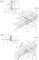
- Ausführungsbeispiele der Erfindung sind im Folgenden anhand der Zeichnung dargestellt. Es zeigen:
- Fig. 1
- eine schematische Schnittdarstellung durch ein Bauwerk,
- Fig. 2
- eine ausschnittsweise schematische Darstellung der zugkraftübertragenden Mittel des Bauwerks nach
Fig. 1 in Blickrichtung des Pfeils II inFig. 1 , - Fig. 3
- eine schematische Seitenansicht der Einrichtung zur Verbindung der beiden Bauwerksteile bei geöffnetem Verwahrkasten,
- Fig. 4
- eine schematische perspektivische Darstellung der Einrichtung aus
Fig. 3 bei geöffnetem Verwahrkasten, - Fig. 5
- eine schematische Seitenansicht der Einrichtung aus den
Fig. 3 und 4 bei geschlossenem Verwahrkasten, - Fig. 6
- eine schematische perspektivische Darstellung der Einrichtung aus
Fig. 5 bei geschlossenem Verwahrkasten, - Fig. 7 bis Fig. 10
- schematische perspektivische Darstellungen des ersten Bauwerksteils und der am ersten Bauwerksteil angeordneten Elemente zur Übertragung von Druckkräften und Querkräften der Einrichtung zur Verbindung der Bauwerksteile.
-
Fig. 1 zeigt schematisch einen Ausschnitt eines Bauwerks 50. Das Bauwerk 50 weist ein erstes Bauwerksteil 2, im Ausführungsbeispiel eine Gebäudedecke, und ein zweites Bauwerksteil 3, im Ausführungsbeispiel eine Balkonplatte, auf. Das zweite Bauwerksteil 3 ist über ein thermisch isolierendes Bauelement 1 an dem ersten Bauwerksteil 2 thermisch isolierend und kraftübertragend angebunden. Die lastaufnehmenden Bauwerksteile 2 und 3 sind aus Beton, im Ausführungsbeispiel aus stahlbewehrtem Beton ausgebildet. Das lastaufnehmende Bauwerksteil 3 ist nach seiner Herstellung an dem ersten lastaufnehmenden Bauwerksteil 2 fixiert worden. Dadurch kann das lastaufnehmende Bauwerksteil 3 beispielsweise im Fertigteilwerk mit hoher Güte hergestellt und auf der Baustelle sehr schnell am Bauwerksteil 2 fixiert werden, wodurch Kranzeiten verkürzt und dadurch Herstellkosten verringert werden. Das zweite Bauwerksteil 3 kann beispielsweise ein als Fertigteil hergestellter Balkon sein. - Das thermisch isolierende Bauelement 1 umfasst einen Isolierkörper 5, der in einer Trennfuge 4 zwischen dem ersten Bauwerksteil 2 und dem zweiten Bauwerksteil 3 angeordnet ist. Der Isolierkörper 5 weist eine erste Längsseite 6 auf, die an dem ersten Bauwerksteil 2 angeordnet ist. Die zweite, gegenüberliegende Längsseite 7 verläuft benachbart zum zweiten Bauwerksteil 3. Im Ausführungsbeispiel ist zwischen dem Isolierkörper 5 und dem zweiten Bauwerksteil 3 ein schmaler Spalt gebildet. Es kann jedoch auch vorgesehen sein, dass das zweite Bauwerksteil 3 an dem Isolierkörper 5 anliegt.
- Wie
Fig. 2 zeigt, weist der Isolierkörper 5 einen Verwahrkasten 33 auf, der mit Isoliermaterial 32 gefüllt ist. Vorteilhaft ist der Verwahrkasten 33 aus Kunststoff hergestellt. Der Verwahrkasten 33 ist insbesondere durch ein oder mehrere Strangpressprofile aus Kunststoff hergestellt. Das Isoliermaterial 32 ist bevorzugt Mineralwolle. Es kann jedoch auch ein anderes Isoliermaterial vorgesehen sein. Der Verwahrkasten 33 ist vorteilhaft an seinen Längsseiten 6 und 7 geschlossen ausgebildet. - Vorteilhaft erstrecken sich ein oder mehrere Verwahrkästen 33 über die gesamte Länge der Dehnfuge 4. Benachbarte Verwahrkästen 33 sind dabei vorteilhaft so angeordnet, dass sie mit ihren Stirnseiten 34 aneinander angrenzen oder - bei abgewinkeltem Verlauf der Trennfuge 4 - dass eine Stirnseite 34 eines Verwahrkastens 33 an eine Längsseite 6 eines angrenzenden Verwahrkastens 33 angrenzt. Die Stirnseiten 34 des Verwahrkastens 33 sind auch in den
Figuren 7 und 8 dargestellt. - Der Verwahrkasten 33 weist eine Längsrichtung 28 auf, die in Längsrichtung der Dehnfuge 4 ausgerichtet ist. Die Längsrichtung 28 verläuft im Einbauzustand vorzugsweise horizontal. Die Stirnseiten 34 verlaufen quer, insbesondere senkrecht zur Längsrichtung 28. Der Verwahrkasten 33 weist eine Hochrichtung 30 auf, wie
Fig. 1 zeigt, die senkrecht zur Längsrichtung 28 verläuft. Die Hochrichtung 30 verläuft im Einbauzustand vorzugsweise senkrecht. Der Verwahrkasten 33 weist eine inFig. 1 gezeigte Querrichtung 29 auf, die von der ersten Längsseite 6 zur gegenüberliegenden Längsseite 7 verläuft. Die Querrichtung 29 ist senkrecht zur Längsrichtung 28 und senkrecht zur Hochrichtung 30 ausgerichtet. Die Querrichtung 29 verläuft im Einbauzustand vorzugsweise horizontal. - Wie
Fig. 1 zeigt, weist der Verwahrkasten 33 eine in Längsrichtung 28 ausgerichtete, die Längsseiten 6 und 7 verbindende Unterseite 8 und eine in Längsrichtung 28 ausgerichtete, die Längsseiten 6 und 7 verbindende Oberseite 47 auf. Die Oberseite 47 ist im Einbauzustand oberhalb der Unterseite 8 angeordnet. An der Oberseite 47 und der Unterseite 8 ist der Verwahrkasten 33 vorteilhaft geschlossen ausgebildet. An den quer zur Längsrichtung 28 verlaufenden Stirnseiten 34 kann der Verwahrkasten 33 offen oder geschlossen ausgebildet sein. - Das thermisch isolierende Bauelement 1 bildet mit weiteren Elementen eine Einrichtung zur kraftübertragenden Anbindung des zweiten Bauwerksteils 3 am ersten Bauwerksteil 2. Die Einrichtung besteht aus dem thermisch isolierenden Bauelement 1, das am ersten Bauwerksteil 2 fixiert ist, sowie weiteren am zweiten Bauwerksteil 3 angeordneten Mitteln zur Kraftübertragung. Die am zweiten Bauwerksteil 3 angeordneten Mittel zur Kraftübertragung sind mit den im ersten Bauwerksteil 2 angeordneten Mitteln zur Kraftübertragung vorteilhaft lösbar verbunden. Dadurch ist eine nachträgliche Anbindung des zweiten Bauwerksteils 3 an dem ersten Bauwerksteil 2 möglich.
- Zur Zugkraftübertragung zwischen den Bauwerksteilen 2 und 3 umfasst die Einrichtung erste Zugstäbe 9, die in das erste Bauwerksteil 2 eingebettet sind, sowie zweite Zugstäbe 10, die in das zweite Bauwerksteil 3 eingebettet sind. Die Zugstäbe 9 und 10 sind miteinander über eine Verbindungseinrichtung 35 kraftübertragend verbunden. Die Verbindungseinrichtung 35 ist im Verwahrkasten 33 angeordnet. Die ersten Zugstäbe 9 ragen durch die erste Längsseite 6 in den Verwahrkasten 33. Die zweiten Zugstäbe 10 ragen durch die zweite Längsseite 7 in den Verwahrkasten 33.
- Die Verbindungseinrichtung 35 umfasst im Ausführungsbeispiel eine Verbindungsplatte 11. Die ersten Zugstäbe 9 sind mit der Verbindungsplatte 11 fest verbunden, im Ausführungsbeispiel über Schweißverbindungen 15 (
Fig. 2 ). Die Verbindungsplatte 11 ist im Ausführungsbeispiel im Verwahrkasten 33 an der Innenseite der zweiten Längsseite 7 angeordnet. Dadurch ergibt sich eine bauraumsparende Anordnung und Schraubverbindungen 40 der zweiten Zugstäbe 10 sind gut zugänglich. Die zweiten Zugstäbe 10 sind an der Verbindungsplatte 11 verschraubt. Die Verbindungsplatte 11 weist Öffnungen 36 (Fig. 1 ) auf, durch die die zweiten Zugstäbe 10 in den Innenraum des Verwahrkastens 33 ragen. Die zweiten Zugstäbe 10 weisen an ihren in den Verwahrkasten 33 ragenden Enden Gewindeabschnitte 41. Die Gewindeabschnitte 41 bilden mit auf die Gewindeabschnitte 41 aufgeschraubten Befestigungsmuttern 14 Schraubverbindungen 40. Über die Schraubverbindungen 40 sind die zweiten Zugstäbe 10 mit der Verbindungsplatte 11 verbunden. An der Seite der Verbindungsplatte 11, die der zweiten Längsseite 7 abgewandt angeordnet ist, ist jeweils eine Befestigungsmutter 14 auf einen Gewindeabschnitt 41 jedes Zugstabs 10 aufgeschraubt. Im Ausführungsbeispiel ist zwischen den Befestigungsmuttern 14 und der Verbindungsplatte 11 jeweils eine Scheibe 21 angeordnet. - Die ersten Zugstäbe 9 und die zweiten Zugstäbe 10 ragen auf gegenüberliegenden Seiten von der Verbindungsplatte 11 weg. Die Zugstäbe 9 und 10 enden im Innenraum des Verwahrkastens 33.
- In alternativer Ausgestaltung kann vorgesehen sein, dass sowohl die ersten Zugstäbe 9 als auch die zweiten Zugstäbe 10 über Schraubverbindungen 40 mit der Verbindungsplatte 11 verbunden sind. Auch eine andere kraftübertragende Verbindung der Zugstäbe 9 und 10 kann vorteilhaft sein. Die Verbindungseinrichtung 35 ist dabei so ausgebildet, dass die Zugstäbe 9 und 10 nach der Herstellung der Gebäudeteile 2 und 3 miteinander verbunden werden können.
- Zur Übertragung von Druckkräften und Querkräften ist eine Auflage 17 am zweiten Bauwerksteil 2 angeordnet. Die Auflage 17 ist im Ausführungsbeispiel als Auflagewinkel ausgebildet. Die Auflage 17 bildet vorteilhaft einen Teil des thermisch isolierenden Bauelements 1 und ist insbesondere am Verwahrkasten 33 unverlierbar gehalten. Die Auflage 17 ist fest mit Querkraftstäben 16 verbunden. Die Querkraftstäbe 16 sind in den Beton des ersten Bauwerksteils 2 eingebettet und dadurch kraftübertragend mit dem ersten Bauwerksteil 2 verbunden. Die Auflage 17 stützt sich in horizontaler Richtung an mindestens einem in das erste Bauwerksteil 2 eingebetteten ersten Druckstab 19 ab. Der erste Druckstab 19 erstreckt sich von der zweiten Längsseite 7 durch die erste Längsseite 6 des Verwahrkastens 33 in das erste Bauwerksteil 2. Der erste Druckstab 19 bildet ein Druckelement. Auch eine andere Gestaltung des Druckelements kann vorteilhaft sein. Es kann vorgesehen sein, dass die Auflage 17 fest mit dem mindestens einen Druckstab 19 verbunden ist.
- Im Ausführungsbeispiel ist in das zweite Bauwerksteil 3 ein Abstützwinkel 31 eingebettet, der an der Auflage 17 aufliegt. Über den Abstützwinkel 31 werden in die Auflage 17 sowohl in horizontaler Richtung wirkende Druckkräfte als auch in vertikaler Richtung wirkende Querkräfte vom zweiten Bauwerksteil 3 eingeleitet. Der Abstützwinkel 31 ist mit mindestens einem zweiten Druckstab 20 verbunden. Der mindestens eine zweite Druckstab 20 ist in das zweite Bauwerksteil 3 eingebettet. Auch eine andere Art der Druckkrafteinleitung in das zweite Bauwerksteil kann vorteilhaft sein.
- Die ersten Zugstäbe 9 weisen Längsachsen 12 auf, und die zweiten Zugstäbe 10 besitzen Längsachsen 13, wie in
Fig. 2 dargestellt ist. WieFig. 1 zeigt, sind die ersten Zugstäbe 9 und die zweiten Zugstäbe 10 auf der gleichen Höhe angeordnet. Die Längsachsen 12 und 13 liegen in einer gemeinsamen, horizontal verlaufenden Ebene 38. Die Ebene 38 verläuft parallel zur Längsrichtung 28 und parallel zur Querrichtung 29. Die Ebene 38 verläuft senkrecht zur Hochrichtung 30. Die Zugstäbe 9 und 10 sind in der Ebene 38 zueinander versetzt angeordnet. WieFig. 2 zeigt, weisen die Längsachsen 12 und 13 benachbarter Zugstäbe 9 und 10 im Ausführungsbeispiel einen in Längsrichtung 28 gemessenen Versatz a zueinander auf. - Die Unterseite 8 des Verwahrkastens 33 verläuft näherungsweise in einer Ebene mit einer Unterseite 45 der Auflage 17 und einer Unterseite 46 des zweiten Bauwerksteils 3.
- Die
Fig. 3 bis 6 zeigen die Gestaltung des Verwahrkastens 33 im Einzelnen. Wie dieFig. 3 und 4 zeigen, ist der Verwahrkasten 33 durch einen Grundkörper 42 und einen Deckel 43 gebildet. In denFig. 3 und 4 ist der Deckel 43 abgenommen dargestellt. Der Deckel 43 kann in Richtung des Pfeils 48 auf den Grundkörper 42 aufgesetzt und mit diesem verbunden werden. In dem inFig. 3 und 4 dargestellten Zustand bei abgenommenem Deckel 43 ist eine Zugangsöffnung 44 offen. Über die Zugangsöffnung 44 ist die Verbindungseinrichtung 35 von außerhalb des Verwahrkastens 33 zugänglich. Die zweiten Zugstäbe 10 können durch Öffnungen in der Verbindungsplatte 11 hindurchgesteckt und anschließend über die Befestigungsmuttern 14 fixiert werden. Die Befestigungsmuttern 14 sind dabei durch die Zugangsöffnung 44 von außen zugänglich. Nach der Fixierung der Befestigungsmuttern 14 kann der Grundkörper 42 mit Isoliermaterial, vorzugsweise mit Mineralwolle gefüllt und anschließend der Deckel 43 aufgesetzt und fixiert werden. Der Deckel 43 kann insbesondere über eine lösbare Verbindung, beispielsweise über eine Schnappverbindung, eine Klemmverbindung oder eine Rastverbindung am Grundkörper 42 fixiert werden. Die lösbare Verbindung ist vorteilhaft so gestaltet, dass der Deckel 43 zerstörungsfrei wieder abgenommen werden kann. Auch eine andere Verbindung von Deckel 43 und Grundkörper 42 kann vorgesehen sein, beispielsweise eine Klebverbindung. - Wie
Fig. 3 und Fig. 4 auch zeigen, ist an der zweiten Längsseite 7 des Verwahrkastens 33 ein Schalungskörper 37 angeordnet, der im zweiten Bauwerksteil 3 eingebettet ist. Der Schalungskörper 37 bildet Aussparungen für Wangen 18 der Auflage 17 (Fig. 7 ). Am Schalungskörper 37 liegt der Abstützwinkel 31 an, wieFig. 3 zeigt. Wie dieFig. 4 und 6 zeigen, sind am Abstützwinkel 31 im Ausführungsbeispiel zwei zweite Druckstäbe 20 fixiert. Auch eine andere Anzahl zweiter Druckstäbe 20 kann vorgesehen sein. - Wie die
Fig. 3 bis 6 zeigen, erstreckt sich die Zugangsöffnung 33 über die gesamte in Querrichtung 29 gemessene Breite b und die gesamte in Längsrichtung 28 gemessene Länge c des Verwahrkastens 32. Wie dieFig. 4 und 6 auch zeigen, ist der Verwahrkasten 33 an seinen senkrecht zur Längsrichtung 28 liegenden Stirnseiten 34 offen ausgebildet. Es kann jedoch auch vorgesehen sein, dass der Verwahrkasten 33 in geschlossenem Zustand vollständig geschlossen ausgebildet ist. - Der Grundkörper 42 ist im Ausführungsbeispiel U-förmig ausgebildet und bildet die Unterseite 8 sowie die Längsseiten 6 und 7 des Verwahrkastens 33. Der Deckel 42 ist im Querschnitt ebenfalls U-förmig ausgebildet, wobei die Schenkel des den Deckel 42 bildenen Us kurz ausgebildet sind.
- Die
Fig. 7 bis 10 zeigen das thermisch isolierende Bauelement 1 am ersten Bauwerksteil 2 im Einzelnen. Die ersten Zugstäbe 9 sind dabei lediglich schematisch und ohne die Verbindungseinrichtung 35 dargestellt. Die Verbindungsplatte 11, an der die Zugstäbe 9 im Verwahrkasten 33 enden, ist nicht gezeigt. - Die Auflage 17 des thermisch isolierenden Bauelements 1 weist zwei Schenkel 24 und 25 auf, die im Ausführungsbeispiel rechtwinklig zueinander ausgerichtet sind. Die Schenkel 24 und 25 verlaufen parallel zur Längsrichtung 28 des Verwahrkastens 33. Der erste Schenkel 24 verläuft parallel zur Hochrichtung 30. Der erste Schenkel 24 ist im Einbauzustand am Bauwerk 50 vorteilhaft vertikal ausgerichtet. Der erste Schenkel 24 bildet an der dem Verwahrkasten 33 abgewandten Seite eine Anlagefläche 22 zur Übertragung von Druckkräften. Der zweite Schenkel 25 verläuft parallel zur Querrichtung 29 und ist im Einbauzustand vorteilhaft horizontal ausgerichtet. Am zweiten Schenkel 25 ist an der im Einbauzustand nach oben weisenden Seite eine Auflagefläche 23 zur Übertragung von Querkräften ausgebildet. Wie die
Fig. 9 und 10 auch zeigen, verläuft der zweite Schenkel 25 der Auflage 17 nahe der Unterseite 8 des Isolierkörpers 5. Auf der Auflagefläche 23 kann das zweite Bauwerksteil 3 aufgelegt und dann über die Schraubverbindungen 40 am ersten Bauwerksteil 2 fixiert werden. Der von den beiden Schenkeln 24 und 25 aufgespannte Raum ist an den Enden der Auflage 17 von quer zur Längsrichtung 28 verlaufenden Wangen 18 geschlossen. - Die Querkraftstäbe 16 sind im ersten Bauwerksteil 2 eingebettet und weisen einen geneigt zur Hochrichtung 30 und geneigt zur Querrichtung 29 verlaufenden Abschnitt 26 auf. Im Einbauzustand fällt der geneigt verlaufende Abschnitt 26 vom ersten Bauwerksteil 2 zum zweiten Bauwerksteil 3 hin ab. Die geneigt verlaufenden Abschnitte 26 der beiden Querkraftstäbe 16 verlaufen an den einander abgewandten Außenseiten der Wangen 18. Jeder geneigte Abschnitt 26 ist unmittelbar an einer Wange 18 fixiert, im Ausführungsbeispiel durch Schweißen. Der geneigt verlaufende Abschnitt 26 des mindestens einen Querkraftstabs 16 ragt durch den Isolierkörper 5.
- Die Auflage 17 ist im gezeigten Ausführungsbeispiel außerhalb des Verwahrkastens 33 angeordnet, und zwar an der der ersten Längsseite 6 abgewandten Längsseite 7 des Verwahrkastens 33. Die Auflage 17 ragt dadurch in den Bereich des zweiten Bauwerksteils 3. An der dem Verwahrkasten 33 zugewandten Seite des ersten Schenkels 24 sind die ersten Druckstäbe 19 am ersten Schenkel 24 fixiert. Die Druckstäbe 19 sind als vergleichsweise lange, gerade Stäbe ausgebildet, die zur Druckkraftübertragung in den Beton des ersten Bauwerksteils 2 eingebettet sind. Die Druckstäbe 19 können an der Auflage 17 angeschraubt, angeschweißt oder auf andere Weise befestigt sein. Auch eine andere Gestaltung der Elemente zur Druckkraftübertragung kann vorteilhaft sein.
- Vorteilhaft besteht die Auflage 17 aus Metall. Die Auflage 17 ist insbesondere einschließlich der mindestens einen Wange 18 aus Blech, bevorzugt aus mindestens zwei miteinander verbundenen Blechteilen, gebildet.
- In alternativer, nicht dargestellter Ausführungsvariante kann auch vorgesehen sein, dass sowohl die Zugstäbe 10 als auch die Zugstäbe 9 an der Verbindungsplatte 11 über Befestigungsmuttern 14 fixiert sind. Vorteilhaft ist zwischen jeder Befestigungsmutter 14 und der Verbindungsplatte 11 eine Scheibe 21 angeordnet. Die Scheiben 21 können jedoch auch entfallen.
Claims (14)
- Einrichtung zur nachträglichen thermisch isolierenden, kraftübertragenden Anbindung eines zweiten lastaufnehmenden Bauwerksteils (3) an ein erstes lastaufnehmendes Bauwerksteil (2), insbesondere einer Balkonplatte an einer Gebäudedecke, wobei die Einrichtung einen Isolierkörper (5) zur Anordnung in einer Trennfuge (4) zwischen dem ersten Bauwerksteil (2) und dem zweiten Bauwerksteil (3) aufweist, wobei der Isolierkörper (5) durch einen mit Isoliermaterial (32) gefüllten, formstabilen Verwahrkasten (33) gebildet ist, wobei der Verwahrkasten (33) eine erste, zur Anordnung an dem ersten Bauwerksteil (2) vorgesehene Längsseite (6) und eine gegenüberliegende zweite Längsseite (7) aufweist, wobei der Verwahrkasten (33) eine Längsrichtung (28), eine senkrecht zur Längsrichtung (28) und von der ersten Längsseite (6) zur zweiten Längsseite (7) verlaufende Querrichtung (29) und eine senkrecht zur Längsrichtung (28) und senkrecht zur Querrichtung (29) verlaufende Hochrichtung (30) aufweist, wobei die Einrichtung mindestens ein Druckelement zur Übertragung von Druckkräften zwischen dem ersten Bauwerksteil (2) und dem zweiten Bauwerksteil (3) aufweist, das sich zumindest von der ersten Längsseite (6) zu der zweiten Längsseite (7) des Verwahrkastens (33) erstreckt, wobei die Einrichtung erste Zugstäbe (9) und zweite Zugstäbe (10) sowie eine Verbindungseinrichtung (35) zur nachträglichen kraftübertragenden Verbindung der zweiten Zugstäbe (10) mit den ersten Zugstäben (9) umfasst,
dadurch gekennzeichnet, dass die ersten Zugstäbe (9) an der ersten Längsseite (6) in den Verwahrkasten (33) ragen, dass die zweiten Zugstäbe (10) an der zweiten Längsseite (7) in den Verwahrkasten (33) ragen und dass die Verbindungseinrichtung (35) in dem Verwahrkasten (33) angeordnet ist. - Einrichtung nach Anspruch 1,
dadurch gekennzeichnet, dass die ersten Zugstäbe (9) und die zweiten Zugstäbe (10) in einer gemeinsamen senkrecht zur Hochrichtung (30) verlaufenden Ebene (38) angeordnet sind. - Einrichtung nach Anspruch 1 oder 2,
dadurch gekennzeichnet, dass die Verbindungseinrichtung (35) eine in dem Verwahrkasten (33) angeordnete Verbindungsplatte (11) umfasst, an der die ersten Zugstäbe (9) und die zweiten Zugstäbe (10) fixiert sind. - Einrichtung nach Anspruch 3,
dadurch gekennzeichnet, dass die Verbindungsplatte (11) an einer Längsseite (6, 7) des Verwahrkastens (33) in dem Verwahrkasten (33) angeordnet ist. - Einrichtung nach einem der Ansprüche 1 bis 4,
dadurch gekennzeichnet, dass die Verbindungseinrichtung (35) mindestens eine Schraubverbindung (40) umfasst. - Einrichtung nach einem der Ansprüche 1 bis 5,
dadurch gekennzeichnet, dass der Verwahrkasten (33) mindestens eine verschließbare Zugangsöffnung (44) aufweist, über die die Verbindungseinrichtung (35) zugänglich ist. - Einrichtung nach Anspruch 6,
dadurch gekennzeichnet, dass die Zugangsöffnung (44) sich über die gesamte in Längsrichtung (28) gemessene Länge (c) und die gesamte in Querrichtung (29) gemessene Breite (b) des Verwahrkastens (33) erstreckt. - Einrichtung nach einem der Ansprüche 1 bis 7,
dadurch gekennzeichnet, dass der Verwahrkasten (33) mit Mineralwolle als Isoliermaterial (32) gefüllt ist. - Einrichtung nach einem der Ansprüche 1 bis 8,
dadurch gekennzeichnet, dass der Verwahrkasten (33) aus Kunststoff ausgebildet ist. - Einrichtung nach einem der Ansprüche 1 bis 9,
dadurch gekennzeichnet, dass der Verwahrkasten (33) einen Grundkörper (42) und mindestens einen mit dem Grundkörper (42) verbindbaren Deckel (43) aufweist. - Einrichtung nach Anspruch 10,
dadurch gekennzeichnet, dass der Deckel (43) lösbar mit dem Grundkörper (42) verbindbar ist. - Einrichtung nach einem der Ansprüche 1 bis 11,
dadurch gekennzeichnet, dass an der zweiten Längsseite (7) des Verwahrkastens (33) mindestens eine Auflage (17) für die vertikale Abstützung des zweiten Bauwerksteils (3) angeordnet ist. - Einrichtung nach einem der Ansprüche 1 bis 12,
dadurch gekennzeichnet, dass mindestens ein Querkraftstab (16) durch den Verwahrkasten (33) ragt. - Bauwerk umfassend ein erstes lastaufnehmendes Bauwerksteil (2) und ein zweites lastaufnehmendes Bauwerksteil (3) aus Beton, insbesondere eine Gebäudedecke und eine Balkonplatte, und eine Einrichtung nach einem der Ansprüche 1 bis 13.
Applications Claiming Priority (1)
| Application Number | Priority Date | Filing Date | Title |
|---|---|---|---|
| DE202021101776.7U DE202021101776U1 (de) | 2021-04-01 | 2021-04-01 | Einrichtung zur nachträglichen thermisch isolierenden, kraftübertragenden Anbindung eines zweiten lastaufnehmenden Bauwerksteils an ein erstes lastaufnehmendes Bauwerksteil und Bauwerk mit einer solchen Einrichtung |
Publications (2)
| Publication Number | Publication Date |
|---|---|
| EP4067593A1 true EP4067593A1 (de) | 2022-10-05 |
| EP4067593B1 EP4067593B1 (de) | 2024-02-28 |
Family
ID=75784721
Family Applications (1)
| Application Number | Title | Priority Date | Filing Date |
|---|---|---|---|
| EP22163162.5A Active EP4067593B1 (de) | 2021-04-01 | 2022-03-21 | Einrichtung zur nachträglichen thermisch isolierenden, kraftübertragenden anbindung eines zweiten lastaufnehmenden bauwerksteils an ein erstes lastaufnehmendes bauwerksteil und bauwerk mit einer solchen einrichtung |
Country Status (6)
| Country | Link |
|---|---|
| US (1) | US12559931B2 (de) |
| EP (1) | EP4067593B1 (de) |
| DE (1) | DE202021101776U1 (de) |
| DK (1) | DK4067593T3 (de) |
| FI (1) | FI4067593T3 (de) |
| PL (1) | PL4067593T3 (de) |
Families Citing this family (2)
| Publication number | Priority date | Publication date | Assignee | Title |
|---|---|---|---|---|
| DE202021000466U1 (de) * | 2021-02-01 | 2021-04-22 | Halfen Gmbh | Einrichtung zur nachträglichen thermisch isolierenden, kraftübertragenden Anbindung eines zweiten lastaufnehmenden Bauwerksteils an ein erstes lastaufnehmendes Bauwerksteil und Bauwerk mit einer solchen Einrichtung |
| DE202023103836U1 (de) * | 2023-07-10 | 2023-10-04 | Leviat Ag | Positioniervorrichtung |
Citations (4)
| Publication number | Priority date | Publication date | Assignee | Title |
|---|---|---|---|---|
| KR101462801B1 (ko) * | 2013-07-26 | 2014-11-21 | 청원화학 주식회사 | 불연속 철근 및 결합 부재를 이용한 열교차단 장치 |
| WO2017086777A1 (en) | 2015-11-16 | 2017-05-26 | T&R Engineering B.V. | Building and balcony |
| GB2567685A (en) * | 2017-10-20 | 2019-04-24 | Insula Ltd | Thermally insulating anchor |
| EP3613910A1 (de) * | 2018-08-22 | 2020-02-26 | iBALKON Dariusz Glaza | Gebäudeverbinder mit wärmedämmung |
Family Cites Families (5)
| Publication number | Priority date | Publication date | Assignee | Title |
|---|---|---|---|---|
| DE102006011336A1 (de) * | 2006-03-09 | 2007-09-13 | Schöck Bauteile GmbH | Bauelement zur Wärmedämmung |
| DK2653625T3 (en) * | 2012-04-20 | 2019-03-11 | Halfen Gmbh | Thermally insulating structural element |
| BE1023762B1 (nl) * | 2016-01-12 | 2017-07-14 | Plakabeton Nv | Constructie-element voor het realiseren van een verbinding tussen thermisch geisoleerde delen van een gebouw |
| GB201819196D0 (en) * | 2018-11-26 | 2019-01-09 | Ancon Ltd | Building element, system and method |
| DE202021000466U1 (de) * | 2021-02-01 | 2021-04-22 | Halfen Gmbh | Einrichtung zur nachträglichen thermisch isolierenden, kraftübertragenden Anbindung eines zweiten lastaufnehmenden Bauwerksteils an ein erstes lastaufnehmendes Bauwerksteil und Bauwerk mit einer solchen Einrichtung |
-
2021
- 2021-04-01 DE DE202021101776.7U patent/DE202021101776U1/de active Active
-
2022
- 2022-03-21 FI FIEP22163162.5T patent/FI4067593T3/fi active
- 2022-03-21 DK DK22163162.5T patent/DK4067593T3/da active
- 2022-03-21 EP EP22163162.5A patent/EP4067593B1/de active Active
- 2022-03-21 PL PL22163162.5T patent/PL4067593T3/pl unknown
- 2022-03-31 US US17/709,456 patent/US12559931B2/en active Active
Patent Citations (4)
| Publication number | Priority date | Publication date | Assignee | Title |
|---|---|---|---|---|
| KR101462801B1 (ko) * | 2013-07-26 | 2014-11-21 | 청원화학 주식회사 | 불연속 철근 및 결합 부재를 이용한 열교차단 장치 |
| WO2017086777A1 (en) | 2015-11-16 | 2017-05-26 | T&R Engineering B.V. | Building and balcony |
| GB2567685A (en) * | 2017-10-20 | 2019-04-24 | Insula Ltd | Thermally insulating anchor |
| EP3613910A1 (de) * | 2018-08-22 | 2020-02-26 | iBALKON Dariusz Glaza | Gebäudeverbinder mit wärmedämmung |
Also Published As
| Publication number | Publication date |
|---|---|
| EP4067593B1 (de) | 2024-02-28 |
| FI4067593T3 (fi) | 2024-03-28 |
| DE202021101776U1 (de) | 2021-04-19 |
| DK4067593T3 (da) | 2024-05-27 |
| US12559931B2 (en) | 2026-02-24 |
| US20220316201A1 (en) | 2022-10-06 |
| PL4067593T3 (pl) | 2024-06-10 |
Similar Documents
| Publication | Publication Date | Title |
|---|---|---|
| EP4036338B1 (de) | Einrichtung zur nachträglichen thermisch isolierenden, kraftübertragenden anbindung eines zweiten lastaufnehmenden bauwerksteils an ein erstes lastaufnehmendes bauwerksteil und bauwerk mit einer solchen einrichtung | |
| EP2653625B1 (de) | Thermisch isolierendes Bauelement | |
| EP4286618B1 (de) | Einrichtung zur nachträglichen kraftübertragenden anbindung eines zweiten lastaufnehmenden bauwerksteils an ein erstes lastaufnehmendes bauwerksteil und bauwerk mit einer solchen einrichtung | |
| EP0338972A1 (de) | Kragplattenanschlusselement | |
| DE1903129B2 (de) | Vorrichtung zum Anschließen eines Trägers an eine Betonstütze | |
| EP4067593B1 (de) | Einrichtung zur nachträglichen thermisch isolierenden, kraftübertragenden anbindung eines zweiten lastaufnehmenden bauwerksteils an ein erstes lastaufnehmendes bauwerksteil und bauwerk mit einer solchen einrichtung | |
| DE19652165C2 (de) | Fertigbauteil für eine auskragende Balkonplatte | |
| DE69000343T2 (de) | Fassadenstruktur des vorhangfassadentyps mit gespannten kabeln oder draehten. | |
| DE1810434C3 (de) | Hochbauwerk | |
| DE10147831B4 (de) | Ständerwand | |
| DE3403537A1 (de) | Balkonfertig-bauelement fuer gebaeude | |
| EP1270833B1 (de) | Bauelement zur Wärmedämmung | |
| DE102019133999A1 (de) | Anordnung zum Verbinden eines Bauwerkteils mit einem dem Bauwerkteil vorgelagerten Außenteil | |
| EP0745734B1 (de) | Kragplatten- und/oder Fugenelement für bewehrte Baukonstruktionen | |
| DE19928757C2 (de) | Montageträgersystem und Verfahren zur Montage eines Fertigbauteils an einem Gebäudeteil | |
| CH690966A5 (de) | Isolierendes Anschlusselement für Kragplatten. | |
| EP2607560B1 (de) | Plattenanschlusselement | |
| EP0796961B1 (de) | Porenbeton-Bauteil mit einer Bewehrungsanordnung | |
| DE102016118014A1 (de) | Binder, insbesondere Dachbinder für eine Halle | |
| EP0106297A2 (de) | Bauelement zur Herstellung von Gebäudewänden aus Beton und mit Hilfe des Bauelementes hergestellte Gebäudewand | |
| EP3835501B1 (de) | Anordnung zum verbinden eines bauwerkteils mit einem dem bauwerkteil vorgelagerten aussenteil | |
| EP4050170B1 (de) | Bauwerk mit thermisch isolierendem bauelement | |
| EP3839162A1 (de) | Thermisch isolierendes bauelement zum einsatz in einer trennfuge zwischen zwei bauwerksteilen und bauwerk | |
| DE9406442U1 (de) | Bauelement | |
| DE29505093U1 (de) | Beton-Fertigteil-Balkon |
Legal Events
| Date | Code | Title | Description |
|---|---|---|---|
| PUAI | Public reference made under article 153(3) epc to a published international application that has entered the european phase |
Free format text: ORIGINAL CODE: 0009012 |
|
| STAA | Information on the status of an ep patent application or granted ep patent |
Free format text: STATUS: THE APPLICATION HAS BEEN PUBLISHED |
|
| AK | Designated contracting states |
Kind code of ref document: A1 Designated state(s): AL AT BE BG CH CY CZ DE DK EE ES FI FR GB GR HR HU IE IS IT LI LT LU LV MC MK MT NL NO PL PT RO RS SE SI SK SM TR |
|
| STAA | Information on the status of an ep patent application or granted ep patent |
Free format text: STATUS: REQUEST FOR EXAMINATION WAS MADE |
|
| 17P | Request for examination filed |
Effective date: 20230323 |
|
| RBV | Designated contracting states (corrected) |
Designated state(s): AL AT BE BG CH CY CZ DE DK EE ES FI FR GB GR HR HU IE IS IT LI LT LU LV MC MK MT NL NO PL PT RO RS SE SI SK SM TR |
|
| GRAP | Despatch of communication of intention to grant a patent |
Free format text: ORIGINAL CODE: EPIDOSNIGR1 |
|
| STAA | Information on the status of an ep patent application or granted ep patent |
Free format text: STATUS: GRANT OF PATENT IS INTENDED |
|
| RIC1 | Information provided on ipc code assigned before grant |
Ipc: E04B 1/00 20060101AFI20231019BHEP |
|
| INTG | Intention to grant announced |
Effective date: 20231110 |
|
| P01 | Opt-out of the competence of the unified patent court (upc) registered |
Effective date: 20231204 |
|
| GRAS | Grant fee paid |
Free format text: ORIGINAL CODE: EPIDOSNIGR3 |
|
| GRAA | (expected) grant |
Free format text: ORIGINAL CODE: 0009210 |
|
| STAA | Information on the status of an ep patent application or granted ep patent |
Free format text: STATUS: THE PATENT HAS BEEN GRANTED |
|
| AK | Designated contracting states |
Kind code of ref document: B1 Designated state(s): AL AT BE BG CH CY CZ DE DK EE ES FI FR GB GR HR HU IE IS IT LI LT LU LV MC MK MT NL NO PL PT RO RS SE SI SK SM TR |
|
| REG | Reference to a national code |
Ref country code: GB Ref legal event code: FG4D Free format text: NOT ENGLISH |
|
| REG | Reference to a national code |
Ref country code: CH Ref legal event code: EP |
|
| REG | Reference to a national code |
Ref country code: DE Ref legal event code: R096 Ref document number: 502022000545 Country of ref document: DE |
|
| REG | Reference to a national code |
Ref country code: IE Ref legal event code: FG4D Free format text: LANGUAGE OF EP DOCUMENT: GERMAN |
|
| REG | Reference to a national code |
Ref country code: FI Ref legal event code: FGE |
|
| REG | Reference to a national code |
Ref country code: NL Ref legal event code: FP |
|
| REG | Reference to a national code |
Ref country code: SE Ref legal event code: TRGR |
|
| REG | Reference to a national code |
Ref country code: DK Ref legal event code: T3 Effective date: 20240523 |
|
| REG | Reference to a national code |
Ref country code: LT Ref legal event code: MG9D |
|
| PG25 | Lapsed in a contracting state [announced via postgrant information from national office to epo] |
Ref country code: IS Free format text: LAPSE BECAUSE OF FAILURE TO SUBMIT A TRANSLATION OF THE DESCRIPTION OR TO PAY THE FEE WITHIN THE PRESCRIBED TIME-LIMIT Effective date: 20240628 |
|
| PG25 | Lapsed in a contracting state [announced via postgrant information from national office to epo] |
Ref country code: LT Free format text: LAPSE BECAUSE OF FAILURE TO SUBMIT A TRANSLATION OF THE DESCRIPTION OR TO PAY THE FEE WITHIN THE PRESCRIBED TIME-LIMIT Effective date: 20240228 |
|
| PG25 | Lapsed in a contracting state [announced via postgrant information from national office to epo] |
Ref country code: GR Free format text: LAPSE BECAUSE OF FAILURE TO SUBMIT A TRANSLATION OF THE DESCRIPTION OR TO PAY THE FEE WITHIN THE PRESCRIBED TIME-LIMIT Effective date: 20240529 |
|
| PG25 | Lapsed in a contracting state [announced via postgrant information from national office to epo] |
Ref country code: HR Free format text: LAPSE BECAUSE OF FAILURE TO SUBMIT A TRANSLATION OF THE DESCRIPTION OR TO PAY THE FEE WITHIN THE PRESCRIBED TIME-LIMIT Effective date: 20240228 Ref country code: RS Free format text: LAPSE BECAUSE OF FAILURE TO SUBMIT A TRANSLATION OF THE DESCRIPTION OR TO PAY THE FEE WITHIN THE PRESCRIBED TIME-LIMIT Effective date: 20240528 |
|
| PG25 | Lapsed in a contracting state [announced via postgrant information from national office to epo] |
Ref country code: ES Free format text: LAPSE BECAUSE OF FAILURE TO SUBMIT A TRANSLATION OF THE DESCRIPTION OR TO PAY THE FEE WITHIN THE PRESCRIBED TIME-LIMIT Effective date: 20240228 |
|
| PG25 | Lapsed in a contracting state [announced via postgrant information from national office to epo] |
Ref country code: RS Free format text: LAPSE BECAUSE OF FAILURE TO SUBMIT A TRANSLATION OF THE DESCRIPTION OR TO PAY THE FEE WITHIN THE PRESCRIBED TIME-LIMIT Effective date: 20240528 Ref country code: LT Free format text: LAPSE BECAUSE OF FAILURE TO SUBMIT A TRANSLATION OF THE DESCRIPTION OR TO PAY THE FEE WITHIN THE PRESCRIBED TIME-LIMIT Effective date: 20240228 Ref country code: IS Free format text: LAPSE BECAUSE OF FAILURE TO SUBMIT A TRANSLATION OF THE DESCRIPTION OR TO PAY THE FEE WITHIN THE PRESCRIBED TIME-LIMIT Effective date: 20240628 Ref country code: HR Free format text: LAPSE BECAUSE OF FAILURE TO SUBMIT A TRANSLATION OF THE DESCRIPTION OR TO PAY THE FEE WITHIN THE PRESCRIBED TIME-LIMIT Effective date: 20240228 Ref country code: GR Free format text: LAPSE BECAUSE OF FAILURE TO SUBMIT A TRANSLATION OF THE DESCRIPTION OR TO PAY THE FEE WITHIN THE PRESCRIBED TIME-LIMIT Effective date: 20240529 Ref country code: ES Free format text: LAPSE BECAUSE OF FAILURE TO SUBMIT A TRANSLATION OF THE DESCRIPTION OR TO PAY THE FEE WITHIN THE PRESCRIBED TIME-LIMIT Effective date: 20240228 Ref country code: BG Free format text: LAPSE BECAUSE OF FAILURE TO SUBMIT A TRANSLATION OF THE DESCRIPTION OR TO PAY THE FEE WITHIN THE PRESCRIBED TIME-LIMIT Effective date: 20240228 |
|
| PG25 | Lapsed in a contracting state [announced via postgrant information from national office to epo] |
Ref country code: PT Free format text: LAPSE BECAUSE OF FAILURE TO SUBMIT A TRANSLATION OF THE DESCRIPTION OR TO PAY THE FEE WITHIN THE PRESCRIBED TIME-LIMIT Effective date: 20240628 |
|
| PG25 | Lapsed in a contracting state [announced via postgrant information from national office to epo] |
Ref country code: PT Free format text: LAPSE BECAUSE OF FAILURE TO SUBMIT A TRANSLATION OF THE DESCRIPTION OR TO PAY THE FEE WITHIN THE PRESCRIBED TIME-LIMIT Effective date: 20240628 Ref country code: LV Free format text: LAPSE BECAUSE OF FAILURE TO SUBMIT A TRANSLATION OF THE DESCRIPTION OR TO PAY THE FEE WITHIN THE PRESCRIBED TIME-LIMIT Effective date: 20240228 |
|
| PG25 | Lapsed in a contracting state [announced via postgrant information from national office to epo] |
Ref country code: SM Free format text: LAPSE BECAUSE OF FAILURE TO SUBMIT A TRANSLATION OF THE DESCRIPTION OR TO PAY THE FEE WITHIN THE PRESCRIBED TIME-LIMIT Effective date: 20240228 |
|
| PG25 | Lapsed in a contracting state [announced via postgrant information from national office to epo] |
Ref country code: EE Free format text: LAPSE BECAUSE OF FAILURE TO SUBMIT A TRANSLATION OF THE DESCRIPTION OR TO PAY THE FEE WITHIN THE PRESCRIBED TIME-LIMIT Effective date: 20240228 |
|
| PG25 | Lapsed in a contracting state [announced via postgrant information from national office to epo] |
Ref country code: SK Free format text: LAPSE BECAUSE OF FAILURE TO SUBMIT A TRANSLATION OF THE DESCRIPTION OR TO PAY THE FEE WITHIN THE PRESCRIBED TIME-LIMIT Effective date: 20240228 |
|
| PG25 | Lapsed in a contracting state [announced via postgrant information from national office to epo] |
Ref country code: SM Free format text: LAPSE BECAUSE OF FAILURE TO SUBMIT A TRANSLATION OF THE DESCRIPTION OR TO PAY THE FEE WITHIN THE PRESCRIBED TIME-LIMIT Effective date: 20240228 Ref country code: SK Free format text: LAPSE BECAUSE OF FAILURE TO SUBMIT A TRANSLATION OF THE DESCRIPTION OR TO PAY THE FEE WITHIN THE PRESCRIBED TIME-LIMIT Effective date: 20240228 Ref country code: RO Free format text: LAPSE BECAUSE OF FAILURE TO SUBMIT A TRANSLATION OF THE DESCRIPTION OR TO PAY THE FEE WITHIN THE PRESCRIBED TIME-LIMIT Effective date: 20240228 Ref country code: EE Free format text: LAPSE BECAUSE OF FAILURE TO SUBMIT A TRANSLATION OF THE DESCRIPTION OR TO PAY THE FEE WITHIN THE PRESCRIBED TIME-LIMIT Effective date: 20240228 |
|
| PG25 | Lapsed in a contracting state [announced via postgrant information from national office to epo] |
Ref country code: LU Free format text: LAPSE BECAUSE OF NON-PAYMENT OF DUE FEES Effective date: 20240321 |
|
| PG25 | Lapsed in a contracting state [announced via postgrant information from national office to epo] |
Ref country code: MC Free format text: LAPSE BECAUSE OF FAILURE TO SUBMIT A TRANSLATION OF THE DESCRIPTION OR TO PAY THE FEE WITHIN THE PRESCRIBED TIME-LIMIT Effective date: 20240228 |
|
| PG25 | Lapsed in a contracting state [announced via postgrant information from national office to epo] |
Ref country code: MC Free format text: LAPSE BECAUSE OF FAILURE TO SUBMIT A TRANSLATION OF THE DESCRIPTION OR TO PAY THE FEE WITHIN THE PRESCRIBED TIME-LIMIT Effective date: 20240228 Ref country code: LU Free format text: LAPSE BECAUSE OF NON-PAYMENT OF DUE FEES Effective date: 20240321 |
|
| REG | Reference to a national code |
Ref country code: DE Ref legal event code: R097 Ref document number: 502022000545 Country of ref document: DE |
|
| PG25 | Lapsed in a contracting state [announced via postgrant information from national office to epo] |
Ref country code: IT Free format text: LAPSE BECAUSE OF FAILURE TO SUBMIT A TRANSLATION OF THE DESCRIPTION OR TO PAY THE FEE WITHIN THE PRESCRIBED TIME-LIMIT Effective date: 20240228 |
|
| PG25 | Lapsed in a contracting state [announced via postgrant information from national office to epo] |
Ref country code: IT Free format text: LAPSE BECAUSE OF FAILURE TO SUBMIT A TRANSLATION OF THE DESCRIPTION OR TO PAY THE FEE WITHIN THE PRESCRIBED TIME-LIMIT Effective date: 20240228 |
|
| PLBE | No opposition filed within time limit |
Free format text: ORIGINAL CODE: 0009261 |
|
| STAA | Information on the status of an ep patent application or granted ep patent |
Free format text: STATUS: NO OPPOSITION FILED WITHIN TIME LIMIT |
|
| PG25 | Lapsed in a contracting state [announced via postgrant information from national office to epo] |
Ref country code: FR Free format text: LAPSE BECAUSE OF NON-PAYMENT OF DUE FEES Effective date: 20240428 |
|
| PG25 | Lapsed in a contracting state [announced via postgrant information from national office to epo] |
Ref country code: IE Free format text: LAPSE BECAUSE OF NON-PAYMENT OF DUE FEES Effective date: 20240321 |
|
| PG25 | Lapsed in a contracting state [announced via postgrant information from national office to epo] |
Ref country code: IE Free format text: LAPSE BECAUSE OF NON-PAYMENT OF DUE FEES Effective date: 20240321 Ref country code: FR Free format text: LAPSE BECAUSE OF NON-PAYMENT OF DUE FEES Effective date: 20240428 |
|
| 26N | No opposition filed |
Effective date: 20241129 |
|
| PG25 | Lapsed in a contracting state [announced via postgrant information from national office to epo] |
Ref country code: SI Free format text: LAPSE BECAUSE OF FAILURE TO SUBMIT A TRANSLATION OF THE DESCRIPTION OR TO PAY THE FEE WITHIN THE PRESCRIBED TIME-LIMIT Effective date: 20240228 |
|
| PGFP | Annual fee paid to national office [announced via postgrant information from national office to epo] |
Ref country code: CH Payment date: 20250401 Year of fee payment: 4 |
|
| PG25 | Lapsed in a contracting state [announced via postgrant information from national office to epo] |
Ref country code: CY Free format text: LAPSE BECAUSE OF FAILURE TO SUBMIT A TRANSLATION OF THE DESCRIPTION OR TO PAY THE FEE WITHIN THE PRESCRIBED TIME-LIMIT; INVALID AB INITIO Effective date: 20220321 |
|
| PG25 | Lapsed in a contracting state [announced via postgrant information from national office to epo] |
Ref country code: TR Free format text: LAPSE BECAUSE OF FAILURE TO SUBMIT A TRANSLATION OF THE DESCRIPTION OR TO PAY THE FEE WITHIN THE PRESCRIBED TIME-LIMIT Effective date: 20240228 |
|
| REG | Reference to a national code |
Ref country code: CH Ref legal event code: U11 Free format text: ST27 STATUS EVENT CODE: U-0-0-U10-U11 (AS PROVIDED BY THE NATIONAL OFFICE) Effective date: 20260401 |
|
| PGFP | Annual fee paid to national office [announced via postgrant information from national office to epo] |
Ref country code: SE Payment date: 20260319 Year of fee payment: 5 |
|
| PGFP | Annual fee paid to national office [announced via postgrant information from national office to epo] |
Ref country code: GB Payment date: 20260324 Year of fee payment: 5 |
|
| PGFP | Annual fee paid to national office [announced via postgrant information from national office to epo] |
Ref country code: NO Payment date: 20260323 Year of fee payment: 5 Ref country code: DK Payment date: 20260324 Year of fee payment: 5 Ref country code: DE Payment date: 20260319 Year of fee payment: 5 |
|
| PGFP | Annual fee paid to national office [announced via postgrant information from national office to epo] |
Ref country code: AT Payment date: 20260301 Year of fee payment: 5 |
|
| PGFP | Annual fee paid to national office [announced via postgrant information from national office to epo] |
Ref country code: FI Payment date: 20260323 Year of fee payment: 5 Ref country code: BE Payment date: 20260319 Year of fee payment: 5 |
|
| PGFP | Annual fee paid to national office [announced via postgrant information from national office to epo] |
Ref country code: NL Payment date: 20260319 Year of fee payment: 5 |
|
| PGFP | Annual fee paid to national office [announced via postgrant information from national office to epo] |
Ref country code: CZ Payment date: 20260317 Year of fee payment: 5 |
|
| PGFP | Annual fee paid to national office [announced via postgrant information from national office to epo] |
Ref country code: PL Payment date: 20260310 Year of fee payment: 5 |