EP4067701A2 - Mécanisme de changement de vitesse, boîte de vitesses à deux rapports et véhicule - Google Patents
Mécanisme de changement de vitesse, boîte de vitesses à deux rapports et véhicule Download PDFInfo
- Publication number
- EP4067701A2 EP4067701A2 EP22165327.2A EP22165327A EP4067701A2 EP 4067701 A2 EP4067701 A2 EP 4067701A2 EP 22165327 A EP22165327 A EP 22165327A EP 4067701 A2 EP4067701 A2 EP 4067701A2
- Authority
- EP
- European Patent Office
- Prior art keywords
- shifting
- gear shifting
- shaft
- gear
- limiting portion
- Prior art date
- Legal status (The legal status is an assumption and is not a legal conclusion. Google has not performed a legal analysis and makes no representation as to the accuracy of the status listed.)
- Granted
Links
Images





Classifications
-
- F—MECHANICAL ENGINEERING; LIGHTING; HEATING; WEAPONS; BLASTING
- F16—ENGINEERING ELEMENTS AND UNITS; GENERAL MEASURES FOR PRODUCING AND MAINTAINING EFFECTIVE FUNCTIONING OF MACHINES OR INSTALLATIONS; THERMAL INSULATION IN GENERAL
- F16H—GEARING
- F16H61/00—Control functions within control units of change-speed- or reversing-gearings for conveying rotary motion ; Control of exclusively fluid gearing, friction gearing, gearings with endless flexible members or other particular types of gearing
- F16H61/26—Generation or transmission of movements for final actuating mechanisms
- F16H61/28—Generation or transmission of movements for final actuating mechanisms with at least one movement of the final actuating mechanism being caused by a non-mechanical force, e.g. power-assisted
-
- F—MECHANICAL ENGINEERING; LIGHTING; HEATING; WEAPONS; BLASTING
- F16—ENGINEERING ELEMENTS AND UNITS; GENERAL MEASURES FOR PRODUCING AND MAINTAINING EFFECTIVE FUNCTIONING OF MACHINES OR INSTALLATIONS; THERMAL INSULATION IN GENERAL
- F16H—GEARING
- F16H3/00—Toothed gearings for conveying rotary motion with variable gear ratio or for reversing rotary motion
- F16H3/44—Toothed gearings for conveying rotary motion with variable gear ratio or for reversing rotary motion using gears having orbital motion
-
- F—MECHANICAL ENGINEERING; LIGHTING; HEATING; WEAPONS; BLASTING
- F16—ENGINEERING ELEMENTS AND UNITS; GENERAL MEASURES FOR PRODUCING AND MAINTAINING EFFECTIVE FUNCTIONING OF MACHINES OR INSTALLATIONS; THERMAL INSULATION IN GENERAL
- F16H—GEARING
- F16H57/00—General details of gearing
- F16H57/02—Gearboxes; Mounting gearing therein
- F16H57/023—Mounting or installation of gears or shafts in the gearboxes, e.g. methods or means for assembly
-
- F—MECHANICAL ENGINEERING; LIGHTING; HEATING; WEAPONS; BLASTING
- F16—ENGINEERING ELEMENTS AND UNITS; GENERAL MEASURES FOR PRODUCING AND MAINTAINING EFFECTIVE FUNCTIONING OF MACHINES OR INSTALLATIONS; THERMAL INSULATION IN GENERAL
- F16H—GEARING
- F16H63/00—Control outputs from the control unit to change-speed- or reversing-gearings for conveying rotary motion or to other devices than the final output mechanism
- F16H63/02—Final output mechanisms therefor; Actuating means for the final output mechanisms
- F16H63/08—Multiple final output mechanisms being moved by a single common final actuating mechanism
- F16H63/16—Multiple final output mechanisms being moved by a single common final actuating mechanism the final output mechanisms being successively actuated by progressive movement of the final actuating mechanism
- F16H63/18—Multiple final output mechanisms being moved by a single common final actuating mechanism the final output mechanisms being successively actuated by progressive movement of the final actuating mechanism the final actuating mechanism comprising cams
-
- F—MECHANICAL ENGINEERING; LIGHTING; HEATING; WEAPONS; BLASTING
- F16—ENGINEERING ELEMENTS AND UNITS; GENERAL MEASURES FOR PRODUCING AND MAINTAINING EFFECTIVE FUNCTIONING OF MACHINES OR INSTALLATIONS; THERMAL INSULATION IN GENERAL
- F16H—GEARING
- F16H63/00—Control outputs from the control unit to change-speed- or reversing-gearings for conveying rotary motion or to other devices than the final output mechanism
- F16H63/02—Final output mechanisms therefor; Actuating means for the final output mechanisms
- F16H63/30—Constructional features of the final output mechanisms
- F16H63/304—Constructional features of the final output mechanisms the final output mechanisms comprising elements moved by electrical or magnetic force
-
- F—MECHANICAL ENGINEERING; LIGHTING; HEATING; WEAPONS; BLASTING
- F16—ENGINEERING ELEMENTS AND UNITS; GENERAL MEASURES FOR PRODUCING AND MAINTAINING EFFECTIVE FUNCTIONING OF MACHINES OR INSTALLATIONS; THERMAL INSULATION IN GENERAL
- F16H—GEARING
- F16H63/00—Control outputs from the control unit to change-speed- or reversing-gearings for conveying rotary motion or to other devices than the final output mechanism
- F16H63/02—Final output mechanisms therefor; Actuating means for the final output mechanisms
- F16H63/30—Constructional features of the final output mechanisms
- F16H63/32—Gear shift yokes, e.g. shift forks
-
- F—MECHANICAL ENGINEERING; LIGHTING; HEATING; WEAPONS; BLASTING
- F16—ENGINEERING ELEMENTS AND UNITS; GENERAL MEASURES FOR PRODUCING AND MAINTAINING EFFECTIVE FUNCTIONING OF MACHINES OR INSTALLATIONS; THERMAL INSULATION IN GENERAL
- F16H—GEARING
- F16H3/00—Toothed gearings for conveying rotary motion with variable gear ratio or for reversing rotary motion
- F16H3/02—Toothed gearings for conveying rotary motion with variable gear ratio or for reversing rotary motion without gears having orbital motion
- F16H3/08—Toothed gearings for conveying rotary motion with variable gear ratio or for reversing rotary motion without gears having orbital motion exclusively or essentially with continuously meshing gears, that can be disengaged from their shafts
- F16H2003/0818—Toothed gearings for conveying rotary motion with variable gear ratio or for reversing rotary motion without gears having orbital motion exclusively or essentially with continuously meshing gears, that can be disengaged from their shafts comprising means for power-shifting
-
- F—MECHANICAL ENGINEERING; LIGHTING; HEATING; WEAPONS; BLASTING
- F16—ENGINEERING ELEMENTS AND UNITS; GENERAL MEASURES FOR PRODUCING AND MAINTAINING EFFECTIVE FUNCTIONING OF MACHINES OR INSTALLATIONS; THERMAL INSULATION IN GENERAL
- F16H—GEARING
- F16H61/00—Control functions within control units of change-speed- or reversing-gearings for conveying rotary motion ; Control of exclusively fluid gearing, friction gearing, gearings with endless flexible members or other particular types of gearing
- F16H61/26—Generation or transmission of movements for final actuating mechanisms
- F16H61/28—Generation or transmission of movements for final actuating mechanisms with at least one movement of the final actuating mechanism being caused by a non-mechanical force, e.g. power-assisted
- F16H2061/2892—Generation or transmission of movements for final actuating mechanisms with at least one movement of the final actuating mechanism being caused by a non-mechanical force, e.g. power-assisted other gears, e.g. worm gears, for transmitting rotary motion to the output mechanism
-
- F—MECHANICAL ENGINEERING; LIGHTING; HEATING; WEAPONS; BLASTING
- F16—ENGINEERING ELEMENTS AND UNITS; GENERAL MEASURES FOR PRODUCING AND MAINTAINING EFFECTIVE FUNCTIONING OF MACHINES OR INSTALLATIONS; THERMAL INSULATION IN GENERAL
- F16H—GEARING
- F16H63/00—Control outputs from the control unit to change-speed- or reversing-gearings for conveying rotary motion or to other devices than the final output mechanism
- F16H63/02—Final output mechanisms therefor; Actuating means for the final output mechanisms
- F16H63/30—Constructional features of the final output mechanisms
- F16H63/304—Constructional features of the final output mechanisms the final output mechanisms comprising elements moved by electrical or magnetic force
- F16H2063/3056—Constructional features of the final output mechanisms the final output mechanisms comprising elements moved by electrical or magnetic force using cam or crank gearing
-
- F—MECHANICAL ENGINEERING; LIGHTING; HEATING; WEAPONS; BLASTING
- F16—ENGINEERING ELEMENTS AND UNITS; GENERAL MEASURES FOR PRODUCING AND MAINTAINING EFFECTIVE FUNCTIONING OF MACHINES OR INSTALLATIONS; THERMAL INSULATION IN GENERAL
- F16H—GEARING
- F16H63/00—Control outputs from the control unit to change-speed- or reversing-gearings for conveying rotary motion or to other devices than the final output mechanism
- F16H63/02—Final output mechanisms therefor; Actuating means for the final output mechanisms
- F16H63/30—Constructional features of the final output mechanisms
- F16H63/304—Constructional features of the final output mechanisms the final output mechanisms comprising elements moved by electrical or magnetic force
- F16H2063/3066—Constructional features of the final output mechanisms the final output mechanisms comprising elements moved by electrical or magnetic force using worm gears
-
- F—MECHANICAL ENGINEERING; LIGHTING; HEATING; WEAPONS; BLASTING
- F16—ENGINEERING ELEMENTS AND UNITS; GENERAL MEASURES FOR PRODUCING AND MAINTAINING EFFECTIVE FUNCTIONING OF MACHINES OR INSTALLATIONS; THERMAL INSULATION IN GENERAL
- F16H—GEARING
- F16H63/00—Control outputs from the control unit to change-speed- or reversing-gearings for conveying rotary motion or to other devices than the final output mechanism
- F16H63/02—Final output mechanisms therefor; Actuating means for the final output mechanisms
- F16H63/30—Constructional features of the final output mechanisms
- F16H2063/3079—Shift rod assembly, e.g. supporting, assembly or manufacturing of shift rails or rods; Special details thereof
-
- F—MECHANICAL ENGINEERING; LIGHTING; HEATING; WEAPONS; BLASTING
- F16—ENGINEERING ELEMENTS AND UNITS; GENERAL MEASURES FOR PRODUCING AND MAINTAINING EFFECTIVE FUNCTIONING OF MACHINES OR INSTALLATIONS; THERMAL INSULATION IN GENERAL
- F16H—GEARING
- F16H63/00—Control outputs from the control unit to change-speed- or reversing-gearings for conveying rotary motion or to other devices than the final output mechanism
- F16H63/02—Final output mechanisms therefor; Actuating means for the final output mechanisms
- F16H63/30—Constructional features of the final output mechanisms
- F16H2063/3089—Spring assisted shift, e.g. springs for accumulating energy of shift movement and release it when clutch teeth are aligned
-
- F—MECHANICAL ENGINEERING; LIGHTING; HEATING; WEAPONS; BLASTING
- F16—ENGINEERING ELEMENTS AND UNITS; GENERAL MEASURES FOR PRODUCING AND MAINTAINING EFFECTIVE FUNCTIONING OF MACHINES OR INSTALLATIONS; THERMAL INSULATION IN GENERAL
- F16H—GEARING
- F16H63/00—Control outputs from the control unit to change-speed- or reversing-gearings for conveying rotary motion or to other devices than the final output mechanism
- F16H63/02—Final output mechanisms therefor; Actuating means for the final output mechanisms
- F16H63/30—Constructional features of the final output mechanisms
- F16H2063/3093—Final output elements, i.e. the final elements to establish gear ratio, e.g. coupling sleeves or other means establishing coupling to shaft
-
- F—MECHANICAL ENGINEERING; LIGHTING; HEATING; WEAPONS; BLASTING
- F16—ENGINEERING ELEMENTS AND UNITS; GENERAL MEASURES FOR PRODUCING AND MAINTAINING EFFECTIVE FUNCTIONING OF MACHINES OR INSTALLATIONS; THERMAL INSULATION IN GENERAL
- F16H—GEARING
- F16H63/00—Control outputs from the control unit to change-speed- or reversing-gearings for conveying rotary motion or to other devices than the final output mechanism
- F16H63/02—Final output mechanisms therefor; Actuating means for the final output mechanisms
- F16H63/30—Constructional features of the final output mechanisms
- F16H63/32—Gear shift yokes, e.g. shift forks
- F16H2063/321—Gear shift yokes, e.g. shift forks characterised by the interface between fork body and shift rod, e.g. fixing means, bushes, cams or pins
-
- F—MECHANICAL ENGINEERING; LIGHTING; HEATING; WEAPONS; BLASTING
- F16—ENGINEERING ELEMENTS AND UNITS; GENERAL MEASURES FOR PRODUCING AND MAINTAINING EFFECTIVE FUNCTIONING OF MACHINES OR INSTALLATIONS; THERMAL INSULATION IN GENERAL
- F16H—GEARING
- F16H63/00—Control outputs from the control unit to change-speed- or reversing-gearings for conveying rotary motion or to other devices than the final output mechanism
- F16H63/02—Final output mechanisms therefor; Actuating means for the final output mechanisms
- F16H63/30—Constructional features of the final output mechanisms
- F16H63/32—Gear shift yokes, e.g. shift forks
- F16H2063/325—Rocker or swiveling forks, i.e. the forks are pivoted in the gear case when moving the sleeve
-
- F—MECHANICAL ENGINEERING; LIGHTING; HEATING; WEAPONS; BLASTING
- F16—ENGINEERING ELEMENTS AND UNITS; GENERAL MEASURES FOR PRODUCING AND MAINTAINING EFFECTIVE FUNCTIONING OF MACHINES OR INSTALLATIONS; THERMAL INSULATION IN GENERAL
- F16H—GEARING
- F16H2200/00—Transmissions for multiple ratios
- F16H2200/0021—Transmissions for multiple ratios specially adapted for electric vehicles
-
- F—MECHANICAL ENGINEERING; LIGHTING; HEATING; WEAPONS; BLASTING
- F16—ENGINEERING ELEMENTS AND UNITS; GENERAL MEASURES FOR PRODUCING AND MAINTAINING EFFECTIVE FUNCTIONING OF MACHINES OR INSTALLATIONS; THERMAL INSULATION IN GENERAL
- F16H—GEARING
- F16H2200/00—Transmissions for multiple ratios
- F16H2200/003—Transmissions for multiple ratios characterised by the number of forward speeds
- F16H2200/0034—Transmissions for multiple ratios characterised by the number of forward speeds the gear ratios comprising two forward speeds
Definitions
- This application relates to the field of power transmission technologies, and in particular, to a gear shifting mechanism, a two-speed gearbox, and a vehicle.
- a gear shifting mechanism of an automobile gearbox is one of the most important components in an automobile transmission system.
- a main function of the gear shifting mechanism is to change a transmission ratio and output an appropriate traction force to wheels through a transmission shaft, to meet requirements of a vehicle in different cases.
- the gear shifting mechanism is an operating mechanism of the gearbox, and is usually fixed on a housing.
- the gear shifting mechanism drives a motor according to an indication of a driver or based on a driving status, to control the gear shifting mechanism to implement forward or backward movement of a shifting fork, so as to control opening and closing of a synchronizer, a dog clutch, or a dry clutch. Closing of the dog clutch means that two tooth surfaces of the dog clutch are meshed.
- This application provides a gear shifting mechanism that is capable of preventing a drive motor from being burnt out due to stalling of the drive motor when a shifting fork pushes a dog clutch to be in a tooth-to-tooth state.
- this application provides a gear shifting mechanism.
- the gear shifting mechanism includes a drive motor, a shifting drum, and a first shifting mechanism.
- the shifting drum includes a gear shifting shaft and a first guiding contour disposed in a circumferential direction of the gear shifting shaft.
- the first guiding contour has a path in an axial direction of the gear shifting shaft.
- the drive motor is capable of driving the gear shifting shaft to rotate around the axial direction of the gear shifting shaft.
- the first shifting mechanism includes an inner shaft, an outer hub, a first coupling pin, a first shifting fork, and an elastic component.
- the outer hub is sleeved on the inner shaft and is capable of moving relative to an axial direction of the inner shaft.
- the outer hub and the gear shifting shaft are movably connected in the axial direction of the gear shifting shaft.
- the outer hub and the gear shifting shaft are fixedly connected in the circumferential direction of the gear shifting shaft.
- One end of the first coupling pin is fixed on an outer side of the outer hub, and the other end of the first coupling pin is inserted into the first guiding contour and is capable of sliding in the first guiding contour.
- the first shifting fork is fixed on the inner shaft and is located on the outer side of the outer hub.
- the elastic component is sleeved on the inner shaft and is located between the inner shaft and the outer hub. There are a first limiting portion and a second limiting portion between the outer hub and the inner shaft. The second limiting portion is located on a side, of the first limiting portion, that is away from the first shifting fork. The elastic component is located between the first limiting portion and the second limiting portion in the axial direction of the inner shaft.
- the first limiting portion is connected to one of the outer hub and the inner shaft, and the second limiting portion is connected to the other of the outer hub and the inner shaft.
- a benefit of disposing the elastic component between the outer hub and the inner shaft lies in that, the elastic component can continue absorbing an acting force when a first gear shifting tooth portion and a second gear shifting tooth portion are attached to each other, to absorb an axial acting force that occurs when a dog clutch is in a tooth-to-tooth state, thereby preventing the drive motor from being burnt out due to stalling of the drive motor.
- an orthographic projection of the first guiding contour in the axial direction of the gear shifting shaft is a straight line with a specific length.
- the first guiding contour is a groove type guiding contour or an opening type guiding contour.
- the first coupling pin is connected and fixed to the outer hub through soldering or integral molding or by using a screw.
- the first limiting portion may be connected and fixed to one of the outer hub and the inner shaft through soldering or integral molding
- the second limiting portion may be connected and fixed to the other of the outer hub and the inner shaft through soldering or integral molding.
- two ends of the elastic component are fixedly connected to the first limiting portion and the second limiting portion respectively.
- a first end of the elastic component may be fixedly connected to the first limiting portion through soldering or by using a hook, or the like, and a second end of the elastic component may be fixedly connected to the second limiting portion through soldering or by using a hook, or the like.
- Shapes of structures of the first limiting portion and the second limiting portion are not limited.
- the first limiting portion and the second limiting portion may be bosses, snap rings, or the like.
- the elastic component may be a spring, a clip, or the like.
- two ends of the elastic component abut against the first limiting portion and the second limiting portion respectively.
- a blocking portion is further disposed on a side, of the first limiting portion, that is away from the second limiting portion, and the blocking portion is fixedly connected to the inner shaft.
- a first end of the elastic component is fixedly connected to the first limiting portion, and a second end of the elastic component abuts against the second limiting portion. In some implementations, a first end of the elastic component abuts against the first limiting portion, and a second end of the elastic component is fixedly connected to the second limiting portion.
- the first shifting fork is adjacent to the first limiting portion, and orthographic projections of the first limiting portion and the first shifting fork on a radial profile of the inner shaft at least partially overlap.
- the first shifting mechanism further includes a hub-rotation limiting component.
- One end of the hub-rotation limiting component is disposed with a first limiting portion sleeved on the outer hub.
- a first limiting plane is disposed on an inner surface of the first limiting portion.
- a second limiting plane matching the first limiting plane is disposed on the outer hub.
- the first limiting plane is attached to the second limiting plane.
- the other end of the hub-rotation limiting component is disposed with a second limiting portion.
- the second limiting portion includes a limiting curved surface that is concave toward the first limiting portion.
- the limiting curved surface surrounds a part of a surface of the gear shifting shaft and is spaced from the gear shifting shaft.
- the gear shifting mechanism further includes a worm and a worm gear that are meshed with each other.
- the worm is connected to the drive motor.
- the worm gear is sleeved on the gear shifting shaft and is fixedly connected to the gear shifting shaft.
- the drive motor operates, the worm is driven to rotate, and the worm drives the worm gear to rotate, so as to drive the gear shifting shaft to rotate.
- the second guiding contour and the worm gear are fixedly connected, and may be integrally formed.
- the shifting drum further includes a second guiding contour disposed in the circumferential direction of the gear shifting shaft.
- the second guiding contour has a path in the axial direction of the gear shifting shaft.
- the gear shifting mechanism further includes a second shifting mechanism.
- the second shifting mechanism includes a second coupling pin, a second shifting fork, and a supporting shaft.
- the second coupling pin is connected to a first end of the second shifting fork and is located in the second guiding contour.
- a via is disposed in the middle of the second shifting fork.
- the supporting shaft is inserted into the via.
- the second shifting fork is capable of rotating relative to the supporting shaft.
- a distance between the first end of the second shifting fork and the supporting shaft is greater than a distance between the second end of the second shifting fork and the supporting shaft.
- an end face of the second end of the second shifting fork is an arc surface.
- the second end of the second shifting fork includes at least two supporting points.
- the second shifting mechanism further includes a push pin, and the second end of the second shifting fork abuts against one end of the push pin.
- the second end of the second shifting fork is configured to be disconnected from and connected to a second gear shifting connection mechanism.
- the second gear shifting connection mechanism is a friction clutch.
- a path, in the second guiding contour, that is used to control connection and disconnection of the friction clutch is a curved path.
- this application provides a two-speed gearbox.
- the two-speed gearbox includes a first gear shifting connection mechanism and the gear shifting mechanism according to any one of the foregoing implementations.
- the first gear shifting connection mechanism is connected to the first shifting fork.
- the first shifting fork controls connection and disconnection of the first gear shifting connection mechanism through axial movement.
- the two-speed gear shifting mechanism further includes a second gear shifting connection mechanism.
- the second shifting fork controls connection and disconnection of the second gear shifting connection mechanism through axial movement.
- the two-speed gearbox further includes a first gear apparatus and a second gear apparatus.
- the first gear apparatus includes a first gear and a first rotary shaft.
- the first gear shifting connection mechanism When the first gear shifting connection mechanism is in a connected state, the first gear is connected to the first rotary shaft.
- the two-speed gearbox may transmit a first shifting power through the first gear and the first rotary shaft.
- the first shifting power is at a low gear.
- the first gear shifting connection mechanism is in a disconnected state, the first gear is disconnected from the first rotary shaft. In this case, no first shifting power can be transmitted between the first gear and the first rotary shaft.
- the second gear apparatus includes a second gear and a second rotary shaft.
- the two-speed gearbox may transmit a second shifting power through the second gear and the second rotary shaft.
- the second shifting power is at a high gear.
- the second gear shifting connection mechanism is in a disconnected state, the second gear is disconnected from the second rotary shaft. In this case, no second shifting power can be transmitted between the second gear and the second rotary shaft.
- this application provides a vehicle.
- the vehicle includes front wheels, rear wheels, a vehicle body connected between the front wheels and the rear wheels, and the foregoing two-speed gearbox.
- the two-speed gearbox is mounted on the vehicle body.
- the vehicle further includes a reduction gear and a differential.
- An intermediate shaft in the two-speed gearbox is connected to the final gear.
- the differential is connected between two front wheels or between the front wheels and the rear wheels.
- the final gear can reduce a rotational speed of the intermediate shaft.
- the differential is configured to adjust a difference between rotational speeds of gears.
- the vehicle includes an automobile, an electric vehicle, or a special operation vehicle.
- the electric vehicle includes a two-wheeled, three-wheeled, or four-wheeled electric vehicle.
- the special operation vehicle includes a variety of vehicles with specific functions, for example, an engineering rescue vehicle, a sprinkler vehicle, a sewage suction vehicle, a cement mixer truck, a lifting vehicle, and a medical vehicle.
- first and second in this specification are merely intended for a purpose of description, and shall not be understood as an indication or implication of relative importance or implicit indication of a quantity of indicated technical features. Therefore, a feature limited by “first” or “second” may explicitly or implicitly include one or more features. In the descriptions of this application, unless otherwise stated, "a plurality of' means two or more than two.
- orientation terms such as “top” and “bottom” are defined relative to orientations of structures in the accompanying drawings. It should be understood that these orientation terms are relative concepts used for relative description and clarification, and may correspondingly change according to changes in the orientations of the structures in the accompanying drawings.
- the gear shifting mechanism 10 includes a drive motor 100, a shifting drum 200, and a first shifting mechanism 300.
- the shifting drum 200 includes a gear shifting shaft 210 and a first guiding contour 220 disposed in a circumferential direction of the gear shifting shaft 210.
- the first guiding contour 220 has a path in an axial direction of the gear shifting shaft 210.
- the drive motor 100 is capable of driving the gear shifting shaft 210 to rotate around the axial direction of the gear shifting shaft 210.
- the path of the first guiding contour 220 encircles the gear shifting shaft 210 once in the circumferential direction of the gear shifting shaft 210, and has a specific path in the axial direction of the gear shifting shaft 210.
- an orthographic projection of the first guiding contour 220 in the axial direction of the gear shifting shaft 210 is a straight line with a specific length.
- the first guiding contour 220 is but is not limited to a groove type guiding contour or an opening type guiding contour, and is a groove type guiding contour in this implementation.
- the groove type guiding contour is a groove structure that has an opening only on one side and has a groove bottom on the other side.
- the opening type guiding contour is a guiding contour having only one sliding surface, and a component slides on the sliding surface.
- 230 in FIG. 2 indicates an opening type guiding contour.
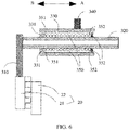
- the first shifting mechanism 300 includes a first shifting fork 310, an inner shaft 320, an outer hub 330, a first coupling pin 340, and an elastic component 350 (as shown in FIG. 5 ).
- the outer hub 330 is sleeved on the inner shaft 320 and is capable of moving relative to an axial direction of the inner shaft 320.
- the outer hub 330 and the gear shifting shaft 210 are movably connected in the axial direction of the gear shifting shaft 210 (refer to FIG. 4 ).
- the outer hub 330 and the gear shifting shaft 210 are fixedly connected in the circumferential direction of the gear shifting shaft 210.
- the outer hub 330 can move only relative to the gear shifting shaft 210 in the axial direction of the gear shifting shaft 210, but cannot rotate relative to the gear shifting shaft 210 in the circumferential direction of the gear shifting shaft 210, and the outer hub 33 sleeved on the inner shaft 320 cannot rotate relative to the gear shifting shaft 210 around the axial direction of the gear shifting shaft 210, either.
- the outer hub 330 is further prevented, by using a hub-rotation limiting component 360, from rotating on its own axis around the inner shaft 320 (as shown in FIG. 3 ).
- a housing is disposed outside the gear shifting mechanism 10.
- the inner shaft 320 and the gear shifting shaft 210 are limited on the housing, so that the inner shaft 320 can move relative to the gear shifting shaft 210 in the axial direction of the gear shifting shaft 210, and the gear shifting shaft 210 can only rotate on its own axis, but cannot move in its own axial direction.
- a manner of limiting the inner shaft 320 and the gear shifting shaft 210 on the housing is not limited in this application, provided that the inner shaft 320 can move relative to the gear shifting shaft 210 in the axial direction of the gear shifting shaft 210 rather than being fixedly locked.
- first coupling pin 340 is fixed to an outer side of the outer hub 330 (as shown in FIG. 3 ), and the other end of the first coupling pin 340 is inserted into the first guiding contour 220 and is capable of sliding in the first guiding contour 220.
- the first coupling pin 340 may be connected and fixed to the outer hub 330 through soldering or integral molding or by using a screw.
- the first coupling pin 340 connected to the outer hub 330 can also move only relative to the gear shifting shaft 210 in the axial direction of the gear shifting shaft 210, but cannot rotate around the axial direction of the gear shifting shaft 210.
- the first shifting fork 310 is fixed on the inner shaft 320 and is located on the outer side of the outer hub 330 (as shown in FIG. 4 ). When the inner shaft 320 moves in an axial direction, the first shifting fork 310 may be driven to move in the axial direction of the inner shaft 320.
- the elastic component 350 is sleeved on the inner shaft 320 and is located between the inner shaft 320 and the outer hub 330. There are a first limiting portion 331 and a second limiting portion 332 between the outer hub 330 and the inner shaft 320. The second limiting portion 332 is located on a side, of the first limiting portion 331, that is away from the first shifting fork 310. The elastic component 350 is located between the first limiting portion 331 and the second limiting portion 332 in an axial direction of the inner shaft 320.
- the first limiting portion 331 is connected to one of the outer hub 330 and the inner shaft 320
- the second limiting portion 332 is connected to the other of the outer hub 330 and the inner shaft 320.
- the first limiting portion 331 is connected to the outer hub 330, and the second limiting portion 332 is connected to the inner shaft 320.
- the first limiting portion 331 may be connected and fixed to the outer hub 330 through soldering or integral molding.
- the second limiting portion 332 may be connected and fixed to the inner shaft 320 through soldering or integral molding.
- a first end 351 of the elastic component 350 is fixedly connected to the first limiting portion 331, and a second end 352 of the elastic component 350 is fixedly connected to the second limiting portion 332, to fixedly connect the first end 351 of the elastic component 350 to the outer hub 330, and fixedly connect the second end 352 of the elastic component 350 to the inner shaft 320.
- the first end 351 of the elastic component 350 may be fixedly connected to the first limiting portion 331 through soldering or by using a hook, or the like.
- the second end 352 of the elastic component 350 may be fixedly connected to the second limiting portion 332 through soldering or by using a hook, or the like.
- Shapes of structures of the first limiting portion 331 and the second limiting portion 332 are not limited.
- the first limiting portion 331 and the second limiting portion 332 may be bosses, snap rings, or the like.
- the elastic component 350 may be a spring, a clip, or the like.
- the following describes an operating process of the first gear shifting mechanism 300 with reference to FIG. 1 , FIG. 3 , and FIG. 5 .
- the gear shifting shaft 210 is driven to rotate around the axial direction of the gear shifting shaft 210.
- the first coupling pin 340 and the outer hub 330 can move only relative to the gear shifting shaft 210 in the axial direction of the gear shifting shaft 210, but cannot rotate around the axial direction of the gear shifting shaft 210, and the first guiding contour 220 has a path in the axial direction of the gear shifting shaft 210.
- the outer hub 330 follows the first coupling pin 340 to move in the axial direction of the gear shifting shaft 210 toward a direction A (as shown in FIG.
- the outer hub 330 drives, by using the first limiting portion 331, the first end 351 of the elastic component 350 to move in the axial direction toward the direction A, and the second end 352 of the elastic component 350 is driven by a force of the first end 351 to push, by using the second limiting portion 332, the inner shaft 320 to move in the axial direction toward the direction A, and drive the first shifting fork 310 fixedly connected to the inner shaft 320 to move in the axial direction toward the direction A.
- the first shifting fork 310 controls connection and disconnection of a first gear shifting connection mechanism 20 through axial movement.
- the first gear shifting connection mechanism 20 is capable of switching between a connected state and a disconnected state (as shown in FIG. 17 ).
- the first shift coupling mechanism 20 is a component in a first gear apparatus of a two-speed gearbox 40.
- the first gear shifting connection mechanism 20 is not limited to a clutch or synchronizer.
- the axial movement of the first shifting fork 310 can control axial movement of the clutch or the synchronizer.
- the first gear shifting connection mechanism 20 is configured to connect a first gear 41 and a first rotary shaft 42 in the first gear apparatus. When the first gear shifting connection mechanism 20 is in the connected state, the first gear 41 is connected to the first rotary shaft 42.
- the two-speed gearbox 40 may transmit a first shifting power through the first gear 41 and the first rotary shaft 42.
- the first shifting power is at a low gear.
- the first gear shifting connection mechanism 20 When the first gear shifting connection mechanism 20 is in the disconnected state, the first gear 41 is disconnected from the first rotary shaft 42. In this case, no first shifting power can be transmitted between the first gear 41 and the first rotary shaft 42.
- the first gear shifting connection mechanism 20 is a dog clutch, and the first gear shifting connection mechanism 20 includes a first gear shifting tooth portion 21 and a second gear shifting tooth portion 22.
- An end, of the first shifting fork 310, that is away from the inner shaft 320 is connected to the first gear shifting tooth portion 21.
- the first shifting fork 310 moves in the axial direction toward the direction A and drives the first gear shifting tooth portion 21 and the second gear shifting tooth portion 22 to be attached tooth to tooth, the first gear shifting tooth portion 21 and the second gear shifting tooth portion 22 have not been meshed.
- the first coupling pin 340 continues moving in the axial direction toward the direction A to a target location, the outer hub 330 is driven to continue compressing the elastic component 350, and the elastic component 350 absorbs an acting force that drives movement to the target location.
- the fluctuation is transmitted to the first gear shifting connection mechanism 20, so that the first gear shifting tooth portion 21 and the second gear shifting tooth portion 22 are staggered at a moment when the rotational speed fluctuates.
- the acting force absorbed by the elastic component 350 is released, so that the first gear shifting tooth portion 21 and the second gear shifting tooth portion 22 are meshed.
- a benefit of disposing the elastic component 350 between the outer hub 330 and the inner shaft 320 lies in that, the elastic component 350 can continue absorbing an acting force when the first gear shifting tooth portion 21 and the second gear shifting tooth portion 22 are attached to each other, to absorb an axial acting force that occurs when the dog clutch is in a tooth-to-tooth state, thereby preventing the drive motor 100 from being burnt out due to stalling of the drive motor 100.
- the first shifting fork 310 moves in an opposite direction, that is, moves in the axial direction toward a direction B, to detach the first gear shifting tooth portion 21 from the second gear shifting tooth portion 22.
- the first limiting portion 331 is fixedly connected to the inner shaft 320
- the second limiting portion 332 is fixedly connected to the outer hub 330.
- the outer hub 330 drives, by using the second limiting portion 332, the second end 352 of the elastic component 350 to move in the axial direction toward the direction A, and the first end 351 of the elastic component 350 is driven by a pulling force of the second end 352 to pull the inner shaft 320 to move in the axial direction toward the direction A, and drive the first shifting fork 310 fixedly connected to the inner shaft 320 to move in the axial direction toward the direction A.
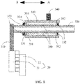
- FIG. 8 A difference from the implementation shown in FIG. 5 lies in that, in a possible implementation, the two ends of the elastic component 350 abut against the first limiting portion 331 and the second limiting portion 332 respectively. Abutting means that two parts are not fixedly connected, but are adjacent in locations.
- a blocking portion 333 is further disposed on a side, of the first limiting portion 331, that is away from the second limiting portion 332, and the blocking portion 333 is fixedly connected to the inner shaft 320.
- the two ends of the elastic component 350 are not fixedly connected to the first limiting portion 331 or the second limiting portion 332. Therefore, when there is no blocking portion 333, when the outer hub 330 moves in the axial direction toward the direction B, the first limiting portion 331 detaches from the elastic component 350, and the inner shaft 320 cannot be driven to move in the axial direction toward the direction B. In this case, the blocking portion 333 needs to be added, so that the first limiting portion 331 pushes the blocking portion 333, to drive the inner shaft 320 to move.
- the first end 351 of the elastic component 350 may be fixedly connected to the first limiting portion 331, and the second end 352 of the elastic component 350 may abut against the second limiting portion 332.
- the first end 351 of the elastic component 350 abuts against the first limiting portion 331, and the second end 352 of the elastic component 350 is fixedly connected to the second limiting portion 332.
- FIG. 9 A difference from the implementation shown in FIG. 8 lies in that, there is no blocking portion 333 on the inner shaft 320, but the first shifting fork 310 is adjacent to the first limiting portion 331. Orthographic projections of the first limiting portion 331 and the first shifting fork 310 on a radial profile of the inner shaft 320 at least partially overlap. Therefore, when the outer hub 330 moves in the axial direction toward the direction B, the first limiting portion 331 pushes the first shifting fork 310 and the inner shaft 320 to move.
- the outer hub 330 is pushed back in the axial direction toward the direction B after the inner shaft 320 moves in the axial direction toward the direction A and reaches the target location, the outer hub 300 returns to an original location, and continues to push the first shifting fork 310 to move in the axial direction toward the direction B.
- the first shifting mechanism 300 further includes the hub-rotation limiting component 360.
- One end of the hub-rotation limiting component 360 is disposed with a first limiting portion 361 sleeved on the outer hub 330.
- a first limiting plane 362 is disposed on an inner surface of the first limiting portion 361.
- a second limiting plane 363 matching the first limiting plane 362 is disposed on the outer hub 330.
- the first limiting plane 362 is attached to the second limiting plane 363.
- the other end of the hub-rotation limiting component 360 is disposed with a second limiting portion 364.
- the second limiting portion 364 includes a limiting curved surface 365 that is concave toward the first limiting portion 361.
- the limiting curved surface 365 surrounds a part of a surface of the gear shifting shaft 210 and is spaced from the gear shifting shaft 210.
- the outer hub 330 cannot rotate on its own axis under actions of the first limiting plane 362, the second limiting plane 363, and the limiting curved surface 365.
- a wall of the first guiding contour 220 also has an acting force in the axial direction and an acting force in a counterclockwise direction ⁇ on the first coupling pin 340.
- the acting force in the counterclockwise direction ⁇ causes a tendency that the outer hub 330 connected to the first coupling pin 340 rotates around an axis of the outer hub 330, and a tendency that the first coupling pin 340 detaches from the first guiding contour 220.
- the first limiting portion 361 and the outer hub 330 remain fixed relative to each other, that is, the outer hub 330 cannot rotate on its own axis relative to the first limiting portion 361.
- the outer hub 330 is to rotate around an axial direction of the outer hub 330, the limiting curved surface 365 of the second limiting portion 364 abuts against the gear shifting shaft 210, and end points 366 of the limiting curved surface 365 press against the gear shifting shaft 210. Therefore, the first limiting portion 361 in the hub-rotation limiting component 360 cannot rotate, the outer hub 330 cannot rotate on its own axis (as shown in FIG.
- the gear shifting shaft 210 can overcome a friction force between the limiting curved surface 365 and the gear shifting shaft 210, and rotate around the axial direction of the gear shifting shaft 210.
- the hub-rotation limiting component 360 may alternatively have another structure. This is not limited in this application, provided that the outer hub 330 is prevented from rotating on its own axis around the axial direction of the outer hub 330 when the gear shifting shaft 210 rotates.
- the gear shifting mechanism 10 further includes a worm 401 and a worm gear 402 that are meshed with each other.
- the worm 401 is connected to the drive motor 100.
- the worm gear 402 is sleeved on the gear shifting shaft 210 and is fixedly connected to the gear shifting shaft 210.
- the drive motor 100 operates, the worm 401 is driven to rotate, and the worm drives the worm gear 402 to rotate, so as to drive the gear shifting shaft 210 to rotate.
- a power of the drive motor 100 is transmitted to the gear shifting shaft 210 by using the worm 401 and the worm gear 402. This saves space compared with power transmission by using two or more gears.
- the shifting drum 200 further includes a second guiding contour 230 disposed in the circumferential direction of the gear shifting shaft 210.
- the second guiding contour 230 has a path in the axial direction of the gear shifting shaft 210.
- the path of the second guiding contour 230 encircles the gear shifting shaft 210 once in the circumferential direction of the gear shifting shaft 210, and has a specific path in the axial direction of the gear shifting shaft 210.
- an orthographic projection of the second guiding contour 230 in the axial direction of the gear shifting shaft 210 is a straight line with a specific length.
- the second guiding contour 230 is but is not limited to a groove type guiding contour or an opening type guiding contour, and is an opening type guiding contour in this implementation.
- the gear shifting mechanism 10 further includes a second shifting mechanism 400.
- the second shifting mechanism 400 includes a second coupling pin 410, a second shifting fork 420, and a supporting shaft 430.
- the second coupling pin 410 is connected to a first end 421 of the second shifting fork 420 and is located in the second guiding contour 230 (as shown in FIG. 3 ).
- a via 403 is disposed in the middle of the second shifting fork 420.
- the supporting shaft 430 is inserted into the via 403.
- the supporting shaft 430 may be fixed to the housing of the gear shifting mechanism 10 or a housing of the two-speed gearbox.
- the supporting shaft 430 is fixed, and the supporting shaft 430 is inserted into the via 403 to constitute a fixed support of the second shifting fork 420.
- the second shifting fork 420 is capable of rotating relative to the supporting shaft 430.
- the second guiding contour 230 and the worm gear 402 are fixedly connected, and may be integrally formed to save space.
- the second gear shifting connection mechanism 30 is capable of switching between a connected state and a disconnected state (as shown in FIG. 17 ).
- the second shift coupling mechanism 30 is a component in a second gear apparatus of the two-speed gearbox 40.
- the second gear shifting connection mechanism 30 is configured to connect a second gear 43 and a second rotary shaft 44 in the second gear apparatus.
- the second gear shifting connection mechanism 30 is in the connected state, the second gear 43 is connected to the second rotary shaft 44.
- the two-speed gearbox 40 may transmit a second shifting power through the second gear 43 and the second rotary shaft 44.
- the second shifting power is at a high gear.
- the second gear shifting connection mechanism 30 is in the disconnected state, the second gear 43 is disconnected from the second rotary shaft 44. In this case, no second shifting power can be transmitted between the second gear 43 and the second rotary shaft 44.
- the second shifting mechanism 400 further includes a push pin 440 (as shown in FIG. 1 ), and the second end 422 of the second shifting fork 420 abuts against one end of the push pin 440.
- the other end of the push pin 440 is configured to be connected to the second gear shifting connection mechanism 30.
- a distance between the first end 421 of the second shifting fork 420 and the supporting shaft 430 is greater than a distance between the second end 422 of the second shifting fork 420 and the supporting shaft 430 (as shown in FIG. 12 ).
- the supporting shaft 430 forms a lever, so that the distance between the first end 421 of the second shifting fork 420 and the supporting shaft 430 is greater than the distance between the second end 422 of the second shifting fork 420 and the supporting shaft 430. This can amplify an acting force of the second end 422 of the second shifting fork 420, and therefore can effectively control connection and disconnection of the second gear shifting connection mechanism 30.
- an end face, used to act on the second gear shifting connection mechanism 30, of the second end 422 of the second shifting fork 420 is an arc surface (as shown in FIG. 12 ).
- the end face of the second end 422 is set to be an arc surface. Therefore, it can be ensured that the end face of the second end 422 of the second shifting fork 420 always abuts against the push pin 440. Further, it can be ensured that an acting force in the axial direction can still be applied to the push pin 440 when the second end 422 moves in an arc shape.
- the arc end face of the second end 422 abuts against the push pin 440.
- the arc end face of the second end 422 can continuously abut against a central axis O of the push pin 440, thereby ensuring a smoother pushing force in an axial direction of the push pin 440 toward the direction A.
- the second end 422 of the second shifting fork 420 includes at least two supporting points 423 (as shown in FIG. 12 ). In other words, there may be a plurality of supporting points 423.
- the plurality of supporting points 423 can increase a contact area of an acting force, so that a force applied to the second gear shifting connection mechanism 30 is more uniform.
- a quantity of push pins 440 is the same as that of supporting points 423.
- the second end 422 of the second shifting fork 420 is configured to be disconnected from and connected to the second gear shifting connection mechanism 30.
- the second gear shifting connection mechanism 30 is a friction clutch.
- a path, in the second guiding contour 230, that is used to control connection and disconnection of the friction clutch is a curved path (as shown in FIG. 2 ). Refer to FIG. 14 .
- the friction clutch 30 includes a plurality of friction plates 31. When an external force acts on the plurality of friction plates 31, the friction plates 31 are gradually combined to transmit the acting force. In this case, the friction clutch 30 is in a connected state.
- the second end 422 of the second shifting fork 420 pushes the push pin 440 to move in the axial direction, and the push pin 440 acts on the plurality of friction plates 31.
- the plurality of friction plates 31 can be combined when the push pin 440 moves in the axial direction.
- a relationship between a value of a friction force F between the plurality of friction plates 31 and an axial distance L by which the push pin 440 pushes the friction plates 31 to move is a curve relationship (as shown in FIG. 15 ). Therefore, the path, in the second guiding contour 230, that is used to control connection and disconnection of the friction clutch 30 is set to be a curved path.
- the friction clutch 30 may be a normally open clutch or a normally closed clutch. It should be noted that a structure of the friction clutch 30 is not limited to the structure shown in FIG. 12 , and may be specifically arranged according to an actual requirement. This is not limited in this application.
- FIG. 15 is merely intended to show that the value of the friction force F between the friction plates 31 and the axial distance L by which the second shifting fork 420 pushes the friction plates 31 to move are in a curve relationship, but does not indicate an actual curve relationship. A specific curve relationship needs to be set according to an actual requirement.
- FIG. 16 shows expanded paths of the first guiding contour 220 and the second guiding contour 230 in the shifting drum 200.
- a first direction X indicates a distance by which the first coupling pin 340 or the second coupling pin 410 moves in the axial direction of the gear shifting shaft 210
- a second direction Y indicates a circumferential rotation angle of the gear shifting shaft 210.
- a total rotation angle in the second direction Y is 360°.
- the first coupling pin 340 is at a location at which the path of the first guiding contour 220 is open
- the second coupling pin 410 is at a location at which the path of the second guiding contour 230 is open.
- the “location at which the path of the first guiding contour 220 is open” indicates that the first gear shifting connection mechanism 20 is in the disconnected state. In this case, the first gear 41 and the first rotary shaft 42 in the first gear apparatus 45 are disconnected.
- the “location at which the path of the second guiding contour 230 is open” indicates that the second gear shifting connection mechanism 30 is in the disconnected state. In this case, the second gear 43 and the second rotary shaft 44 in the second gear apparatus 46 are disconnected.
- the first coupling pin 340 is at a location at which the path of the first guiding contour 220 is closed
- the second coupling pin 410 is at a location at which the path of the second guiding contour 230 is closed.
- the "location at which the path of the first guiding contour 220 is closed" indicates that the first gear shifting connection mechanism 20 is in the connected state.
- the first gear 41 and the first rotary shaft 42 in the first gear apparatus 45 are connected, and the first rotary shaft 42 drives the first gear 41 on the first rotary shaft 42 to rotate.
- the "location at which the path of the second guiding contour 230 is open" indicates that the second gear shifting connection mechanism 30 is in the disconnected state.
- the second gear 43 and the second rotary shaft 44 in the second gear apparatus 46 are disconnected. That is, in the case of the 1st gear, the first gear 41 and the first rotary shaft 42 in the first gear apparatus 45 transmit a power, and the second gear 43 and the second rotary shaft 44 in the second gear apparatus 46 have a speed difference and do not transmit a power.
- the first coupling pin 340 is at a location at which the path of the first guide groove 220 is open
- the second coupling pin 410 is at a location at which the path of the second guiding contour 230 is closed.
- the "location at which the path of the first guiding contour 220 is open" indicates that the first gear shifting connection mechanism 20 is in the disconnected state. In this case, the first gear 41 and the first rotary shaft 42 in the first gear apparatus 45 are disconnected, and the first rotary shaft 42 cannot drive the first gear 41 on the first rotary shaft 42 to rotate.
- the "location at which the path of the second guiding contour 230 is closed" indicates that the second gear shifting connection mechanism 30 is in the connected state.
- the second gear 43 and the second rotary shaft 44 in the second gear apparatus 46 are connected, and the second rotary shaft 44 drives the second gear 43 to rotate. That is, in the case of the 2nd gear, the first gear 41 and the first rotary shaft 42 in the first gear apparatus 45 have a speed difference and do not transmit a power, and the second gear 43 and the second rotary shaft 44 in the second gear apparatus 46 transmit a power.
- the first coupling pin 340 is at a location at which the path of the first guiding contour 220 is closed
- the second coupling pin 410 is at a location at which the path of the second guiding contour 230 is closed, to connect the first gear 41 and the first rotary shaft 42 in the first gear apparatus 45, and connect the second gear 43 and the second rotary shaft 44 in the second gear apparatus 46.
- the first gear apparatus 45 and the second gear apparatus 46 simultaneously transmit powers, thereby causing a mutual lockup.
- the path of the second guiding contour 230 is a curve in a process of switching from the 2nd gear to the N gear and a process of switching from the 1st gear to the P position, so that a power is transmitted more smoothly.
- the four states in FIG. 16 may be switched according to a requirement, including but not limited to switching from the 1st gear to the 2nd gear, switching from the 1st gear to the N gear, switching from the 2nd gear to the N gear, switching from the 1st gear to the P position, and switching from the 2nd gear to the P position.
- An implementation of this application further provides a two-speed gearbox 40.
- the two-speed gearbox 40 includes a first gear shifting connection mechanism 20 and the gear shifting mechanism 10 according to any one of the foregoing implementations.
- the first shifting fork 310 controls connection and disconnection of the first gear shifting connection mechanism 20 through axial movement.
- the two-speed gear shifting mechanism 40 further includes a second gear shifting connection mechanism 30.
- the second shifting fork 420 controls connection and disconnection of the second gear shifting connection mechanism 30 through axial movement.
- the two-speed gearbox 40 further includes a first gear apparatus 45 and a second gear apparatus 46.
- the first gear apparatus 45 includes a first gear 41 and a first rotary shaft 42.
- the first gear shifting connection mechanism 20 When the first gear shifting connection mechanism 20 is in a connected state, the first gear 41 is connected to the first rotary shaft 42.
- the two-speed gearbox 40 may transmit a first shifting power through the first gear 41 and the first rotary shaft 42.
- the first shifting power is at a low gear.
- the first gear shifting connection mechanism 20 is in a disconnected state, the first gear 41 is disconnected from the first rotary shaft 42. In this case, no first shifting power can be transmitted between the first gear 41 and the first rotary shaft 42.
- the second gear apparatus 46 includes a second gear 43 and a second rotary shaft 44.
- the second gear shifting connection mechanism 30 When the second gear shifting connection mechanism 30 is in a connected state, the second gear 43 is connected to the second rotary shaft 44. In this case, the two-speed gearbox 40 may transmit a second shifting power through the second gear 43 and the second rotary shaft 44. The second shifting power is at a high gear. When the second gear shifting connection mechanism 30 is in a disconnected state, the second gear 43 is disconnected from the second rotary shaft 44. In this case, no second shifting power can be transmitted between the second gear 43 and the second rotary shaft 44.
- first rotary shaft 42 and the second rotary shaft 44 may be an input shaft, the other may be an intermediate shaft. In some cases, the first rotary shaft 42 and the second rotary shaft 44 may be a same rotary shaft. In some cases, the first gear 41 and the second gear 43 each may include two or more gears. It should be noted that a specific structure of the two-speed gearbox 40 in this application is not limited to the structure shown in FIG. 17 , and a gear and a rotary shaft may be specifically disposed according to an actual requirement.
- an implementation of this application further provides a vehicle 1.
- the vehicle 1 includes front wheels 2, rear wheels 3, a vehicle body 4 connected between the front wheels 2 and the rear wheels 3, and the foregoing two-speed gearbox 40.
- the two-speed gearbox 40 is mounted on the vehicle body 4.
- the vehicle 1 further includes a final gear and a differential.
- An intermediate shaft in the two-speed gearbox 40 is connected to the final gear.
- the differential is connected between two front wheels 2 or between the front wheels 2 and the rear wheels 3.
- the final gear can reduce a rotational speed of the intermediate shaft.
- the differential is configured to adjust a difference between rotational speeds of gears.
- the vehicle 1 includes an automobile, an electric vehicle, or a special operation vehicle.
- the electric vehicle includes a two-wheeled, three-wheeled, or four-wheeled electric vehicle.
- the special operation vehicle includes a variety of vehicles with specific functions, for example, an engineering rescue vehicle, a sprinkler vehicle, a sewage suction vehicle, a cement mixer truck, a lifting vehicle, and a medical vehicle.
Landscapes
- Engineering & Computer Science (AREA)
- General Engineering & Computer Science (AREA)
- Mechanical Engineering (AREA)
- Gear-Shifting Mechanisms (AREA)
Applications Claiming Priority (1)
| Application Number | Priority Date | Filing Date | Title |
|---|---|---|---|
| CN202110350869.9A CN113090753B (zh) | 2021-03-31 | 2021-03-31 | 换档机构、两档换档系统及车辆 |
Publications (3)
| Publication Number | Publication Date |
|---|---|
| EP4067701A2 true EP4067701A2 (fr) | 2022-10-05 |
| EP4067701A3 EP4067701A3 (fr) | 2022-12-21 |
| EP4067701B1 EP4067701B1 (fr) | 2024-02-14 |
Family
ID=76672298
Family Applications (1)
| Application Number | Title | Priority Date | Filing Date |
|---|---|---|---|
| EP22165327.2A Active EP4067701B1 (fr) | 2021-03-31 | 2022-03-30 | Mécanisme de changement de vitesse, boîte de vitesses à deux rapports et véhicule |
Country Status (3)
| Country | Link |
|---|---|
| US (1) | US11933396B2 (fr) |
| EP (1) | EP4067701B1 (fr) |
| CN (1) | CN113090753B (fr) |
Cited By (1)
| Publication number | Priority date | Publication date | Assignee | Title |
|---|---|---|---|---|
| EP4715239A1 (fr) * | 2024-09-18 | 2026-03-25 | Traton AB | Ensemble d'entraînement de véhicule à agencement de changement de vitesse et véhicule |
Families Citing this family (11)
| Publication number | Priority date | Publication date | Assignee | Title |
|---|---|---|---|---|
| EP4001706B1 (fr) * | 2020-11-23 | 2024-02-21 | Volvo Truck Corporation | Dispositif de verrouillage pour une transmission |
| CN113404824B (zh) * | 2021-07-14 | 2024-05-17 | 重庆宗王动力发动机有限公司 | 一种多档动力输出系统 |
| CN114135665A (zh) * | 2022-02-07 | 2022-03-04 | 深圳市悦成汽车技术有限公司 | 一种蓄能式同步器拨叉 |
| CN114458702B (zh) * | 2022-02-18 | 2023-06-02 | 中国第一汽车股份有限公司 | 减速器断开装置、减速器及车辆 |
| CN115045972B (zh) * | 2022-06-06 | 2025-10-03 | 佛山市正泽模型科技有限公司 | 差速器装置及模型车 |
| CN119421803A (zh) * | 2022-07-08 | 2025-02-11 | 莱纳玛公司 | 带小齿轮联接器的双速断开全轮驱动系统(awd)系统 |
| CN115126865B (zh) * | 2022-08-16 | 2023-07-14 | 一汽解放汽车有限公司 | 变速箱同步器操纵机构、变速箱和汽车 |
| CN115234632A (zh) * | 2022-08-22 | 2022-10-25 | 嘉兴国联精密机械有限公司 | 可变速的齿轮箱传动机构 |
| CN116816928B (zh) * | 2023-02-13 | 2024-06-14 | 卓克骑行科技(重庆)有限公司 | 一种变速箱 |
| DE102023113811A1 (de) * | 2023-05-25 | 2024-11-28 | Daimler Truck AG | Schaltvorrichtung für ein zumindest teilweise elektrisch betriebenes Kraftfahrzeug |
| US12523294B2 (en) | 2023-11-14 | 2026-01-13 | Dana Italia S.R.L. | Barrel cam actuator for a transmission |
Family Cites Families (18)
| Publication number | Priority date | Publication date | Assignee | Title |
|---|---|---|---|---|
| DE1210286B (de) * | 1962-06-26 | 1966-02-03 | Helmut Droeschel | Zahnraederwechselgetriebe |
| JPH0755407Y2 (ja) * | 1990-08-17 | 1995-12-20 | 三菱自動車工業株式会社 | シフトフォーク脱落防止用ジョウ |
| DE19530616C2 (de) * | 1995-08-21 | 1998-10-22 | Daimler Benz Ag | Schaltvorrichtung für Zahnräderwechselgetriebe |
| TW200740633A (en) * | 2006-04-28 | 2007-11-01 | Kwang Yang Motor Co | Component of automobile shift lever |
| DE602006009909D1 (de) * | 2006-05-31 | 2009-12-03 | Kwang Yang Motor Co | Getriebeschaltgabel Anordnung für ein Kraftfahrzeug |
| KR101339895B1 (ko) * | 2012-05-29 | 2013-12-10 | (주) 솔텍 | 듀얼 클러치 변속기의 시프트장치 |
| CN103511561B (zh) | 2012-06-15 | 2017-12-01 | 欧瑞康格拉齐亚诺股份公司 | 用于电动机的双齿轮传动装置 |
| EP3336392A4 (fr) * | 2015-08-10 | 2018-07-25 | Yamaha Hatsudoki Kabushiki Kaisha | Transmission et véhicule |
| CN204871456U (zh) * | 2015-08-10 | 2015-12-16 | 宁波市龙嘉摩托车有限公司 | 一种摩托车换档机构 |
| CN205639596U (zh) * | 2016-05-27 | 2016-10-12 | 长城汽车股份有限公司 | 减速器换档装置及车辆 |
| US10982765B2 (en) * | 2016-11-11 | 2021-04-20 | Team Industries, Inc. | Dual cam spring-loaded shifting transmission assembly |
| US11614165B2 (en) * | 2016-12-01 | 2023-03-28 | Kanzaki Kokyukoki Mfg. Co., Ltd. | Shift-drum speed change operation mechanism |
| US20180328487A1 (en) * | 2016-12-01 | 2018-11-15 | Kanzaki Kokyukoki Mfg Co, Ltd. | Shift-drum speed change operation mechanism |
| FR3075301B1 (fr) * | 2017-12-19 | 2019-11-15 | Renault S.A.S. | Dispositif assiste d'entrainement d'une fourchette de passage de rapport d'une boite de vitesses |
| JP6785287B2 (ja) * | 2018-12-21 | 2020-11-18 | 本田技研工業株式会社 | 車両用変速機構造 |
| CN209604492U (zh) * | 2018-12-25 | 2019-11-08 | 重庆先友科技开发有限公司 | 一种车辆自动换档驱动系统 |
| US11873896B2 (en) * | 2021-03-22 | 2024-01-16 | Ghsp, Inc. | Shift actuator for power transfer unit |
| JP2023005679A (ja) * | 2021-06-29 | 2023-01-18 | 株式会社デンソー | 駆動装置 |
-
2021
- 2021-03-31 CN CN202110350869.9A patent/CN113090753B/zh active Active
-
2022
- 2022-03-30 EP EP22165327.2A patent/EP4067701B1/fr active Active
- 2022-03-31 US US17/710,713 patent/US11933396B2/en active Active
Cited By (2)
| Publication number | Priority date | Publication date | Assignee | Title |
|---|---|---|---|---|
| EP4715239A1 (fr) * | 2024-09-18 | 2026-03-25 | Traton AB | Ensemble d'entraînement de véhicule à agencement de changement de vitesse et véhicule |
| WO2026063849A1 (fr) * | 2024-09-18 | 2026-03-26 | Scania Cv Ab | Ensemble d'entraînement de véhicule à agencement de changement de vitesse, et véhicule |
Also Published As
| Publication number | Publication date |
|---|---|
| EP4067701A3 (fr) | 2022-12-21 |
| US11933396B2 (en) | 2024-03-19 |
| US20220221053A1 (en) | 2022-07-14 |
| EP4067701B1 (fr) | 2024-02-14 |
| CN113090753A (zh) | 2021-07-09 |
| CN113090753B (zh) | 2022-07-22 |
Similar Documents
| Publication | Publication Date | Title |
|---|---|---|
| US11933396B2 (en) | Gear shifting mechanism, two-speed gearbox, and vehicle | |
| EP4067704B1 (fr) | Mécanisme de changement de vitesse, boîte de vitesses, groupe motopropulseur et véhicule électrique | |
| CN114962598B (zh) | 一种多功能减速器总成 | |
| JP2003194097A (ja) | トランスミッションのギア抜け防止機構 | |
| US20230272844A1 (en) | Two-speed transmission gearbox of electric vehicle and electric vehicle | |
| CN114801722B (zh) | 一种集成电磁差速锁与两档变速的电驱动总成 | |
| EP4063680B1 (fr) | Système de transmission à deux vitesses et véhicule | |
| CN113586697A (zh) | 扭矩管理器 | |
| CN116816882A (zh) | 一种双速可锁止的扭矩主动分配智能分动器 | |
| CN215793169U (zh) | 一种半轴断开机构、动力传动系统及车辆 | |
| CN112145680A (zh) | 一种可调减速比的自动行走设备及其驱动方法 | |
| CN217944805U (zh) | 双电机电驱动桥系统及车辆 | |
| JP2012096719A (ja) | 駆動力配分装置 | |
| KR20030043801A (ko) | 수동변속기 장착용 자동변속장치. | |
| CN116292878A (zh) | 一种混合动力汽车变速器电磁换挡机构 | |
| CN220828452U (zh) | 一种带可锁止的单向离合结构及电动车变速器总成 | |
| CN211175326U (zh) | 一种汽车拨叉 | |
| US20090250309A1 (en) | Hydraulic Shift System for Power Transfer Devices | |
| KR0146461B1 (ko) | 연속자동 변속장치 | |
| CN210970640U (zh) | 变速驱动桥和具有其的车辆 | |
| CN116141873A (zh) | 双电机电驱动桥系统及车辆 | |
| KR0146449B1 (ko) | 연속자동 변속장치 | |
| CN217003049U (zh) | 减速器及电动汽车 | |
| CN115059700B (zh) | 一种车辆滑行节能装置 | |
| CN223839600U (zh) | 驱动轴的断开机构、驱动轴总成和车辆 |
Legal Events
| Date | Code | Title | Description |
|---|---|---|---|
| PUAI | Public reference made under article 153(3) epc to a published international application that has entered the european phase |
Free format text: ORIGINAL CODE: 0009012 |
|
| STAA | Information on the status of an ep patent application or granted ep patent |
Free format text: STATUS: THE APPLICATION HAS BEEN PUBLISHED |
|
| AK | Designated contracting states |
Kind code of ref document: A2 Designated state(s): AL AT BE BG CH CY CZ DE DK EE ES FI FR GB GR HR HU IE IS IT LI LT LU LV MC MK MT NL NO PL PT RO RS SE SI SK SM TR |
|
| PUAL | Search report despatched |
Free format text: ORIGINAL CODE: 0009013 |
|
| AK | Designated contracting states |
Kind code of ref document: A3 Designated state(s): AL AT BE BG CH CY CZ DE DK EE ES FI FR GB GR HR HU IE IS IT LI LT LU LV MC MK MT NL NO PL PT RO RS SE SI SK SM TR |
|
| RIC1 | Information provided on ipc code assigned before grant |
Ipc: F16H 63/30 20060101ALN20221115BHEP Ipc: F16H 63/18 20060101ALI20221115BHEP Ipc: F16H 63/32 20060101ALI20221115BHEP Ipc: F16H 61/28 20060101AFI20221115BHEP |
|
| STAA | Information on the status of an ep patent application or granted ep patent |
Free format text: STATUS: REQUEST FOR EXAMINATION WAS MADE |
|
| 17P | Request for examination filed |
Effective date: 20230601 |
|
| RBV | Designated contracting states (corrected) |
Designated state(s): AL AT BE BG CH CY CZ DE DK EE ES FI FR GB GR HR HU IE IS IT LI LT LU LV MC MK MT NL NO PL PT RO RS SE SI SK SM TR |
|
| STAA | Information on the status of an ep patent application or granted ep patent |
Free format text: STATUS: EXAMINATION IS IN PROGRESS |
|
| 17Q | First examination report despatched |
Effective date: 20230821 |
|
| GRAJ | Information related to disapproval of communication of intention to grant by the applicant or resumption of examination proceedings by the epo deleted |
Free format text: ORIGINAL CODE: EPIDOSDIGR1 |
|
| STAA | Information on the status of an ep patent application or granted ep patent |
Free format text: STATUS: GRANT OF PATENT IS INTENDED |
|
| GRAP | Despatch of communication of intention to grant a patent |
Free format text: ORIGINAL CODE: EPIDOSNIGR1 |
|
| RIC1 | Information provided on ipc code assigned before grant |
Ipc: F16H 63/30 20060101ALN20231011BHEP Ipc: F16H 63/18 20060101ALI20231011BHEP Ipc: F16H 63/32 20060101ALI20231011BHEP Ipc: F16H 61/28 20060101AFI20231011BHEP |
|
| INTG | Intention to grant announced |
Effective date: 20231027 |
|
| GRAS | Grant fee paid |
Free format text: ORIGINAL CODE: EPIDOSNIGR3 |
|
| P01 | Opt-out of the competence of the unified patent court (upc) registered |
Effective date: 20231130 |
|
| GRAA | (expected) grant |
Free format text: ORIGINAL CODE: 0009210 |
|
| STAA | Information on the status of an ep patent application or granted ep patent |
Free format text: STATUS: THE PATENT HAS BEEN GRANTED |
|
| AK | Designated contracting states |
Kind code of ref document: B1 Designated state(s): AL AT BE BG CH CY CZ DE DK EE ES FI FR GB GR HR HU IE IS IT LI LT LU LV MC MK MT NL NO PL PT RO RS SE SI SK SM TR |
|
| REG | Reference to a national code |
Ref country code: GB Ref legal event code: FG4D |
|
| REG | Reference to a national code |
Ref country code: CH Ref legal event code: EP |
|
| REG | Reference to a national code |
Ref country code: DE Ref legal event code: R096 Ref document number: 602022001905 Country of ref document: DE |
|
| REG | Reference to a national code |
Ref country code: IE Ref legal event code: FG4D |
|
| REG | Reference to a national code |
Ref country code: LT Ref legal event code: MG9D |
|
| REG | Reference to a national code |
Ref country code: NL Ref legal event code: MP Effective date: 20240214 |
|
| PG25 | Lapsed in a contracting state [announced via postgrant information from national office to epo] |
Ref country code: IS Free format text: LAPSE BECAUSE OF FAILURE TO SUBMIT A TRANSLATION OF THE DESCRIPTION OR TO PAY THE FEE WITHIN THE PRESCRIBED TIME-LIMIT Effective date: 20240614 |
|
| PG25 | Lapsed in a contracting state [announced via postgrant information from national office to epo] |
Ref country code: LT Free format text: LAPSE BECAUSE OF FAILURE TO SUBMIT A TRANSLATION OF THE DESCRIPTION OR TO PAY THE FEE WITHIN THE PRESCRIBED TIME-LIMIT Effective date: 20240214 |
|
| PG25 | Lapsed in a contracting state [announced via postgrant information from national office to epo] |
Ref country code: GR Free format text: LAPSE BECAUSE OF FAILURE TO SUBMIT A TRANSLATION OF THE DESCRIPTION OR TO PAY THE FEE WITHIN THE PRESCRIBED TIME-LIMIT Effective date: 20240515 |
|
| REG | Reference to a national code |
Ref country code: AT Ref legal event code: MK05 Ref document number: 1657281 Country of ref document: AT Kind code of ref document: T Effective date: 20240214 |
|
| PG25 | Lapsed in a contracting state [announced via postgrant information from national office to epo] |
Ref country code: NL Free format text: LAPSE BECAUSE OF FAILURE TO SUBMIT A TRANSLATION OF THE DESCRIPTION OR TO PAY THE FEE WITHIN THE PRESCRIBED TIME-LIMIT Effective date: 20240214 Ref country code: RS Free format text: LAPSE BECAUSE OF FAILURE TO SUBMIT A TRANSLATION OF THE DESCRIPTION OR TO PAY THE FEE WITHIN THE PRESCRIBED TIME-LIMIT Effective date: 20240514 Ref country code: HR Free format text: LAPSE BECAUSE OF FAILURE TO SUBMIT A TRANSLATION OF THE DESCRIPTION OR TO PAY THE FEE WITHIN THE PRESCRIBED TIME-LIMIT Effective date: 20240214 |
|
| PG25 | Lapsed in a contracting state [announced via postgrant information from national office to epo] |
Ref country code: ES Free format text: LAPSE BECAUSE OF FAILURE TO SUBMIT A TRANSLATION OF THE DESCRIPTION OR TO PAY THE FEE WITHIN THE PRESCRIBED TIME-LIMIT Effective date: 20240214 |
|
| PG25 | Lapsed in a contracting state [announced via postgrant information from national office to epo] |
Ref country code: AT Free format text: LAPSE BECAUSE OF FAILURE TO SUBMIT A TRANSLATION OF THE DESCRIPTION OR TO PAY THE FEE WITHIN THE PRESCRIBED TIME-LIMIT Effective date: 20240214 |
|
| PG25 | Lapsed in a contracting state [announced via postgrant information from national office to epo] |
Ref country code: RS Free format text: LAPSE BECAUSE OF FAILURE TO SUBMIT A TRANSLATION OF THE DESCRIPTION OR TO PAY THE FEE WITHIN THE PRESCRIBED TIME-LIMIT Effective date: 20240514 Ref country code: NO Free format text: LAPSE BECAUSE OF FAILURE TO SUBMIT A TRANSLATION OF THE DESCRIPTION OR TO PAY THE FEE WITHIN THE PRESCRIBED TIME-LIMIT Effective date: 20240514 Ref country code: NL Free format text: LAPSE BECAUSE OF FAILURE TO SUBMIT A TRANSLATION OF THE DESCRIPTION OR TO PAY THE FEE WITHIN THE PRESCRIBED TIME-LIMIT Effective date: 20240214 Ref country code: LT Free format text: LAPSE BECAUSE OF FAILURE TO SUBMIT A TRANSLATION OF THE DESCRIPTION OR TO PAY THE FEE WITHIN THE PRESCRIBED TIME-LIMIT Effective date: 20240214 Ref country code: IS Free format text: LAPSE BECAUSE OF FAILURE TO SUBMIT A TRANSLATION OF THE DESCRIPTION OR TO PAY THE FEE WITHIN THE PRESCRIBED TIME-LIMIT Effective date: 20240614 Ref country code: HR Free format text: LAPSE BECAUSE OF FAILURE TO SUBMIT A TRANSLATION OF THE DESCRIPTION OR TO PAY THE FEE WITHIN THE PRESCRIBED TIME-LIMIT Effective date: 20240214 Ref country code: GR Free format text: LAPSE BECAUSE OF FAILURE TO SUBMIT A TRANSLATION OF THE DESCRIPTION OR TO PAY THE FEE WITHIN THE PRESCRIBED TIME-LIMIT Effective date: 20240515 Ref country code: FI Free format text: LAPSE BECAUSE OF FAILURE TO SUBMIT A TRANSLATION OF THE DESCRIPTION OR TO PAY THE FEE WITHIN THE PRESCRIBED TIME-LIMIT Effective date: 20240214 Ref country code: ES Free format text: LAPSE BECAUSE OF FAILURE TO SUBMIT A TRANSLATION OF THE DESCRIPTION OR TO PAY THE FEE WITHIN THE PRESCRIBED TIME-LIMIT Effective date: 20240214 Ref country code: BG Free format text: LAPSE BECAUSE OF FAILURE TO SUBMIT A TRANSLATION OF THE DESCRIPTION OR TO PAY THE FEE WITHIN THE PRESCRIBED TIME-LIMIT Effective date: 20240214 Ref country code: AT Free format text: LAPSE BECAUSE OF FAILURE TO SUBMIT A TRANSLATION OF THE DESCRIPTION OR TO PAY THE FEE WITHIN THE PRESCRIBED TIME-LIMIT Effective date: 20240214 |
|
| PG25 | Lapsed in a contracting state [announced via postgrant information from national office to epo] |
Ref country code: PL Free format text: LAPSE BECAUSE OF FAILURE TO SUBMIT A TRANSLATION OF THE DESCRIPTION OR TO PAY THE FEE WITHIN THE PRESCRIBED TIME-LIMIT Effective date: 20240214 Ref country code: PT Free format text: LAPSE BECAUSE OF FAILURE TO SUBMIT A TRANSLATION OF THE DESCRIPTION OR TO PAY THE FEE WITHIN THE PRESCRIBED TIME-LIMIT Effective date: 20240614 |
|
| PG25 | Lapsed in a contracting state [announced via postgrant information from national office to epo] |
Ref country code: SE Free format text: LAPSE BECAUSE OF FAILURE TO SUBMIT A TRANSLATION OF THE DESCRIPTION OR TO PAY THE FEE WITHIN THE PRESCRIBED TIME-LIMIT Effective date: 20240214 Ref country code: PT Free format text: LAPSE BECAUSE OF FAILURE TO SUBMIT A TRANSLATION OF THE DESCRIPTION OR TO PAY THE FEE WITHIN THE PRESCRIBED TIME-LIMIT Effective date: 20240614 Ref country code: PL Free format text: LAPSE BECAUSE OF FAILURE TO SUBMIT A TRANSLATION OF THE DESCRIPTION OR TO PAY THE FEE WITHIN THE PRESCRIBED TIME-LIMIT Effective date: 20240214 Ref country code: LV Free format text: LAPSE BECAUSE OF FAILURE TO SUBMIT A TRANSLATION OF THE DESCRIPTION OR TO PAY THE FEE WITHIN THE PRESCRIBED TIME-LIMIT Effective date: 20240214 |
|
| PG25 | Lapsed in a contracting state [announced via postgrant information from national office to epo] |
Ref country code: DK Free format text: LAPSE BECAUSE OF FAILURE TO SUBMIT A TRANSLATION OF THE DESCRIPTION OR TO PAY THE FEE WITHIN THE PRESCRIBED TIME-LIMIT Effective date: 20240214 |
|
| PG25 | Lapsed in a contracting state [announced via postgrant information from national office to epo] |
Ref country code: SM Free format text: LAPSE BECAUSE OF FAILURE TO SUBMIT A TRANSLATION OF THE DESCRIPTION OR TO PAY THE FEE WITHIN THE PRESCRIBED TIME-LIMIT Effective date: 20240214 |
|
| PG25 | Lapsed in a contracting state [announced via postgrant information from national office to epo] |
Ref country code: EE Free format text: LAPSE BECAUSE OF FAILURE TO SUBMIT A TRANSLATION OF THE DESCRIPTION OR TO PAY THE FEE WITHIN THE PRESCRIBED TIME-LIMIT Effective date: 20240214 Ref country code: CZ Free format text: LAPSE BECAUSE OF FAILURE TO SUBMIT A TRANSLATION OF THE DESCRIPTION OR TO PAY THE FEE WITHIN THE PRESCRIBED TIME-LIMIT Effective date: 20240214 |
|
| PG25 | Lapsed in a contracting state [announced via postgrant information from national office to epo] |
Ref country code: SK Free format text: LAPSE BECAUSE OF FAILURE TO SUBMIT A TRANSLATION OF THE DESCRIPTION OR TO PAY THE FEE WITHIN THE PRESCRIBED TIME-LIMIT Effective date: 20240214 |
|
| PG25 | Lapsed in a contracting state [announced via postgrant information from national office to epo] |
Ref country code: SM Free format text: LAPSE BECAUSE OF FAILURE TO SUBMIT A TRANSLATION OF THE DESCRIPTION OR TO PAY THE FEE WITHIN THE PRESCRIBED TIME-LIMIT Effective date: 20240214 Ref country code: SK Free format text: LAPSE BECAUSE OF FAILURE TO SUBMIT A TRANSLATION OF THE DESCRIPTION OR TO PAY THE FEE WITHIN THE PRESCRIBED TIME-LIMIT Effective date: 20240214 Ref country code: RO Free format text: LAPSE BECAUSE OF FAILURE TO SUBMIT A TRANSLATION OF THE DESCRIPTION OR TO PAY THE FEE WITHIN THE PRESCRIBED TIME-LIMIT Effective date: 20240214 Ref country code: EE Free format text: LAPSE BECAUSE OF FAILURE TO SUBMIT A TRANSLATION OF THE DESCRIPTION OR TO PAY THE FEE WITHIN THE PRESCRIBED TIME-LIMIT Effective date: 20240214 Ref country code: DK Free format text: LAPSE BECAUSE OF FAILURE TO SUBMIT A TRANSLATION OF THE DESCRIPTION OR TO PAY THE FEE WITHIN THE PRESCRIBED TIME-LIMIT Effective date: 20240214 Ref country code: CZ Free format text: LAPSE BECAUSE OF FAILURE TO SUBMIT A TRANSLATION OF THE DESCRIPTION OR TO PAY THE FEE WITHIN THE PRESCRIBED TIME-LIMIT Effective date: 20240214 |
|
| REG | Reference to a national code |
Ref country code: DE Ref legal event code: R097 Ref document number: 602022001905 Country of ref document: DE |
|
| PG25 | Lapsed in a contracting state [announced via postgrant information from national office to epo] |
Ref country code: LU Free format text: LAPSE BECAUSE OF NON-PAYMENT OF DUE FEES Effective date: 20240330 |
|
| PG25 | Lapsed in a contracting state [announced via postgrant information from national office to epo] |
Ref country code: MC Free format text: LAPSE BECAUSE OF FAILURE TO SUBMIT A TRANSLATION OF THE DESCRIPTION OR TO PAY THE FEE WITHIN THE PRESCRIBED TIME-LIMIT Effective date: 20240214 |
|
| PG25 | Lapsed in a contracting state [announced via postgrant information from national office to epo] |
Ref country code: MC Free format text: LAPSE BECAUSE OF FAILURE TO SUBMIT A TRANSLATION OF THE DESCRIPTION OR TO PAY THE FEE WITHIN THE PRESCRIBED TIME-LIMIT Effective date: 20240214 Ref country code: LU Free format text: LAPSE BECAUSE OF NON-PAYMENT OF DUE FEES Effective date: 20240330 |
|
| PG25 | Lapsed in a contracting state [announced via postgrant information from national office to epo] |
Ref country code: IT Free format text: LAPSE BECAUSE OF FAILURE TO SUBMIT A TRANSLATION OF THE DESCRIPTION OR TO PAY THE FEE WITHIN THE PRESCRIBED TIME-LIMIT Effective date: 20240214 |
|
| REG | Reference to a national code |
Ref country code: BE Ref legal event code: MM Effective date: 20240331 |
|
| PLBE | No opposition filed within time limit |
Free format text: ORIGINAL CODE: 0009261 |
|
| STAA | Information on the status of an ep patent application or granted ep patent |
Free format text: STATUS: NO OPPOSITION FILED WITHIN TIME LIMIT |
|
| PG25 | Lapsed in a contracting state [announced via postgrant information from national office to epo] |
Ref country code: IT Free format text: LAPSE BECAUSE OF FAILURE TO SUBMIT A TRANSLATION OF THE DESCRIPTION OR TO PAY THE FEE WITHIN THE PRESCRIBED TIME-LIMIT Effective date: 20240214 |
|
| PG25 | Lapsed in a contracting state [announced via postgrant information from national office to epo] |
Ref country code: BE Free format text: LAPSE BECAUSE OF NON-PAYMENT OF DUE FEES Effective date: 20240331 |
|
| 26N | No opposition filed |
Effective date: 20241115 |
|
| PG25 | Lapsed in a contracting state [announced via postgrant information from national office to epo] |
Ref country code: IE Free format text: LAPSE BECAUSE OF NON-PAYMENT OF DUE FEES Effective date: 20240330 |
|
| PG25 | Lapsed in a contracting state [announced via postgrant information from national office to epo] |
Ref country code: IE Free format text: LAPSE BECAUSE OF NON-PAYMENT OF DUE FEES Effective date: 20240330 Ref country code: BE Free format text: LAPSE BECAUSE OF NON-PAYMENT OF DUE FEES Effective date: 20240331 |
|
| PG25 | Lapsed in a contracting state [announced via postgrant information from national office to epo] |
Ref country code: SI Free format text: LAPSE BECAUSE OF FAILURE TO SUBMIT A TRANSLATION OF THE DESCRIPTION OR TO PAY THE FEE WITHIN THE PRESCRIBED TIME-LIMIT Effective date: 20240214 |
|
| PG25 | Lapsed in a contracting state [announced via postgrant information from national office to epo] |
Ref country code: CY Free format text: LAPSE BECAUSE OF FAILURE TO SUBMIT A TRANSLATION OF THE DESCRIPTION OR TO PAY THE FEE WITHIN THE PRESCRIBED TIME-LIMIT; INVALID AB INITIO Effective date: 20220330 |
|
| REG | Reference to a national code |
Ref country code: CH Ref legal event code: H13 Free format text: ST27 STATUS EVENT CODE: U-0-0-H10-H13 (AS PROVIDED BY THE NATIONAL OFFICE) Effective date: 20251024 |
|
| PG25 | Lapsed in a contracting state [announced via postgrant information from national office to epo] |
Ref country code: TR Free format text: LAPSE BECAUSE OF FAILURE TO SUBMIT A TRANSLATION OF THE DESCRIPTION OR TO PAY THE FEE WITHIN THE PRESCRIBED TIME-LIMIT Effective date: 20240214 |
|
| PG25 | Lapsed in a contracting state [announced via postgrant information from national office to epo] |
Ref country code: CH Free format text: LAPSE BECAUSE OF NON-PAYMENT OF DUE FEES Effective date: 20250331 |
|
| PGFP | Annual fee paid to national office [announced via postgrant information from national office to epo] |
Ref country code: GB Payment date: 20260209 Year of fee payment: 5 |
|
| PGFP | Annual fee paid to national office [announced via postgrant information from national office to epo] |
Ref country code: DE Payment date: 20260204 Year of fee payment: 5 |
|
| PGFP | Annual fee paid to national office [announced via postgrant information from national office to epo] |
Ref country code: FR Payment date: 20260209 Year of fee payment: 5 |