EP4067821A1 - Procédé et appareil de planification de trajet pour véhicule - Google Patents
Procédé et appareil de planification de trajet pour véhicule Download PDFInfo
- Publication number
- EP4067821A1 EP4067821A1 EP19954320.8A EP19954320A EP4067821A1 EP 4067821 A1 EP4067821 A1 EP 4067821A1 EP 19954320 A EP19954320 A EP 19954320A EP 4067821 A1 EP4067821 A1 EP 4067821A1
- Authority
- EP
- European Patent Office
- Prior art keywords
- pose
- vehicle
- parking
- path
- planning
- Prior art date
- Legal status (The legal status is an assumption and is not a legal conclusion. Google has not performed a legal analysis and makes no representation as to the accuracy of the status listed.)
- Withdrawn
Links
- 238000000034 method Methods 0.000 title claims abstract description 113
- 230000004044 response Effects 0.000 claims abstract description 16
- 230000015654 memory Effects 0.000 claims description 52
- 238000012545 processing Methods 0.000 claims description 24
- 238000001514 detection method Methods 0.000 claims description 11
- 238000004590 computer program Methods 0.000 claims description 8
- 230000006870 function Effects 0.000 description 38
- 238000004891 communication Methods 0.000 description 26
- 230000008569 process Effects 0.000 description 22
- 238000010586 diagram Methods 0.000 description 21
- 230000008859 change Effects 0.000 description 9
- 238000005457 optimization Methods 0.000 description 9
- 238000005516 engineering process Methods 0.000 description 8
- 230000002093 peripheral effect Effects 0.000 description 8
- 230000006399 behavior Effects 0.000 description 7
- 238000013473 artificial intelligence Methods 0.000 description 6
- 230000003993 interaction Effects 0.000 description 6
- 238000012986 modification Methods 0.000 description 6
- 230000004048 modification Effects 0.000 description 6
- 241001465754 Metazoa Species 0.000 description 5
- 230000009471 action Effects 0.000 description 5
- 230000005540 biological transmission Effects 0.000 description 5
- 230000001788 irregular Effects 0.000 description 5
- 230000001133 acceleration Effects 0.000 description 4
- 238000013461 design Methods 0.000 description 4
- 230000033001 locomotion Effects 0.000 description 4
- 230000003068 static effect Effects 0.000 description 4
- 230000010267 cellular communication Effects 0.000 description 3
- 230000008878 coupling Effects 0.000 description 3
- 238000010168 coupling process Methods 0.000 description 3
- 238000005859 coupling reaction Methods 0.000 description 3
- 239000000446 fuel Substances 0.000 description 3
- 238000007726 management method Methods 0.000 description 3
- 238000012549 training Methods 0.000 description 3
- NAWXUBYGYWOOIX-SFHVURJKSA-N (2s)-2-[[4-[2-(2,4-diaminoquinazolin-6-yl)ethyl]benzoyl]amino]-4-methylidenepentanedioic acid Chemical compound C1=CC2=NC(N)=NC(N)=C2C=C1CCC1=CC=C(C(=O)N[C@@H](CC(=C)C(O)=O)C(O)=O)C=C1 NAWXUBYGYWOOIX-SFHVURJKSA-N 0.000 description 2
- LFQSCWFLJHTTHZ-UHFFFAOYSA-N Ethanol Chemical compound CCO LFQSCWFLJHTTHZ-UHFFFAOYSA-N 0.000 description 2
- ATUOYWHBWRKTHZ-UHFFFAOYSA-N Propane Chemical compound CCC ATUOYWHBWRKTHZ-UHFFFAOYSA-N 0.000 description 2
- 238000013528 artificial neural network Methods 0.000 description 2
- 238000002485 combustion reaction Methods 0.000 description 2
- 230000006835 compression Effects 0.000 description 2
- 238000007906 compression Methods 0.000 description 2
- 230000007613 environmental effect Effects 0.000 description 2
- 230000007774 longterm Effects 0.000 description 2
- 238000005259 measurement Methods 0.000 description 2
- 238000010295 mobile communication Methods 0.000 description 2
- 238000011160 research Methods 0.000 description 2
- 101001093748 Homo sapiens Phosphatidylinositol N-acetylglucosaminyltransferase subunit P Proteins 0.000 description 1
- HBBGRARXTFLTSG-UHFFFAOYSA-N Lithium ion Chemical compound [Li+] HBBGRARXTFLTSG-UHFFFAOYSA-N 0.000 description 1
- 206010039203 Road traffic accident Diseases 0.000 description 1
- 239000002253 acid Substances 0.000 description 1
- 230000001413 cellular effect Effects 0.000 description 1
- 238000010276 construction Methods 0.000 description 1
- 230000003247 decreasing effect Effects 0.000 description 1
- 229910001416 lithium ion Inorganic materials 0.000 description 1
- 239000011159 matrix material Substances 0.000 description 1
- 238000012544 monitoring process Methods 0.000 description 1
- 238000003058 natural language processing Methods 0.000 description 1
- 230000003287 optical effect Effects 0.000 description 1
- 230000010355 oscillation Effects 0.000 description 1
- 230000008447 perception Effects 0.000 description 1
- 238000003825 pressing Methods 0.000 description 1
- 239000001294 propane Substances 0.000 description 1
- 238000010079 rubber tapping Methods 0.000 description 1
- 238000005070 sampling Methods 0.000 description 1
- 238000012216 screening Methods 0.000 description 1
- 239000000126 substance Substances 0.000 description 1
- 238000012546 transfer Methods 0.000 description 1
- 230000001052 transient effect Effects 0.000 description 1
Images





Classifications
-
- B—PERFORMING OPERATIONS; TRANSPORTING
- B62—LAND VEHICLES FOR TRAVELLING OTHERWISE THAN ON RAILS
- B62D—MOTOR VEHICLES; TRAILERS
- B62D15/00—Steering not otherwise provided for
- B62D15/02—Steering position indicators ; Steering position determination; Steering aids
- B62D15/027—Parking aids, e.g. instruction means
- B62D15/0285—Parking performed automatically
-
- B—PERFORMING OPERATIONS; TRANSPORTING
- B60—VEHICLES IN GENERAL
- B60W—CONJOINT CONTROL OF VEHICLE SUB-UNITS OF DIFFERENT TYPE OR DIFFERENT FUNCTION; CONTROL SYSTEMS SPECIALLY ADAPTED FOR HYBRID VEHICLES; ROAD VEHICLE DRIVE CONTROL SYSTEMS FOR PURPOSES NOT RELATED TO THE CONTROL OF A PARTICULAR SUB-UNIT
- B60W30/00—Purposes of road vehicle drive control systems not related to the control of a particular sub-unit, e.g. of systems using conjoint control of vehicle sub-units
- B60W30/06—Automatic manoeuvring for parking
-
- B—PERFORMING OPERATIONS; TRANSPORTING
- B60—VEHICLES IN GENERAL
- B60W—CONJOINT CONTROL OF VEHICLE SUB-UNITS OF DIFFERENT TYPE OR DIFFERENT FUNCTION; CONTROL SYSTEMS SPECIALLY ADAPTED FOR HYBRID VEHICLES; ROAD VEHICLE DRIVE CONTROL SYSTEMS FOR PURPOSES NOT RELATED TO THE CONTROL OF A PARTICULAR SUB-UNIT
- B60W60/00—Drive control systems specially adapted for autonomous road vehicles
- B60W60/001—Planning or execution of driving tasks
-
- G—PHYSICS
- G01—MEASURING; TESTING
- G01C—MEASURING DISTANCES, LEVELS OR BEARINGS; SURVEYING; NAVIGATION; GYROSCOPIC INSTRUMENTS; PHOTOGRAMMETRY OR VIDEOGRAMMETRY
- G01C21/00—Navigation; Navigational instruments not provided for in groups G01C1/00 - G01C19/00
- G01C21/10—Navigation; Navigational instruments not provided for in groups G01C1/00 - G01C19/00 by using measurements of speed or acceleration
- G01C21/12—Navigation; Navigational instruments not provided for in groups G01C1/00 - G01C19/00 by using measurements of speed or acceleration executed aboard the object being navigated; Dead reckoning
- G01C21/16—Navigation; Navigational instruments not provided for in groups G01C1/00 - G01C19/00 by using measurements of speed or acceleration executed aboard the object being navigated; Dead reckoning by integrating acceleration or speed, i.e. inertial navigation
- G01C21/165—Navigation; Navigational instruments not provided for in groups G01C1/00 - G01C19/00 by using measurements of speed or acceleration executed aboard the object being navigated; Dead reckoning by integrating acceleration or speed, i.e. inertial navigation combined with non-inertial navigation instruments
-
- G—PHYSICS
- G01—MEASURING; TESTING
- G01C—MEASURING DISTANCES, LEVELS OR BEARINGS; SURVEYING; NAVIGATION; GYROSCOPIC INSTRUMENTS; PHOTOGRAMMETRY OR VIDEOGRAMMETRY
- G01C21/00—Navigation; Navigational instruments not provided for in groups G01C1/00 - G01C19/00
- G01C21/20—Instruments for performing navigational calculations
-
- G—PHYSICS
- G01—MEASURING; TESTING
- G01C—MEASURING DISTANCES, LEVELS OR BEARINGS; SURVEYING; NAVIGATION; GYROSCOPIC INSTRUMENTS; PHOTOGRAMMETRY OR VIDEOGRAMMETRY
- G01C21/00—Navigation; Navigational instruments not provided for in groups G01C1/00 - G01C19/00
- G01C21/26—Navigation; Navigational instruments not provided for in groups G01C1/00 - G01C19/00 specially adapted for navigation in a road network
- G01C21/34—Route searching; Route guidance
- G01C21/3407—Route searching; Route guidance specially adapted for specific applications
- G01C21/343—Calculating itineraries
-
- G—PHYSICS
- G01—MEASURING; TESTING
- G01C—MEASURING DISTANCES, LEVELS OR BEARINGS; SURVEYING; NAVIGATION; GYROSCOPIC INSTRUMENTS; PHOTOGRAMMETRY OR VIDEOGRAMMETRY
- G01C21/00—Navigation; Navigational instruments not provided for in groups G01C1/00 - G01C19/00
- G01C21/26—Navigation; Navigational instruments not provided for in groups G01C1/00 - G01C19/00 specially adapted for navigation in a road network
- G01C21/34—Route searching; Route guidance
- G01C21/36—Input/output arrangements for on-board computers
- G01C21/3626—Details of the output of route guidance instructions
-
- B—PERFORMING OPERATIONS; TRANSPORTING
- B60—VEHICLES IN GENERAL
- B60W—CONJOINT CONTROL OF VEHICLE SUB-UNITS OF DIFFERENT TYPE OR DIFFERENT FUNCTION; CONTROL SYSTEMS SPECIALLY ADAPTED FOR HYBRID VEHICLES; ROAD VEHICLE DRIVE CONTROL SYSTEMS FOR PURPOSES NOT RELATED TO THE CONTROL OF A PARTICULAR SUB-UNIT
- B60W2520/00—Input parameters relating to overall vehicle dynamics
- B60W2520/10—Longitudinal speed
-
- B—PERFORMING OPERATIONS; TRANSPORTING
- B60—VEHICLES IN GENERAL
- B60W—CONJOINT CONTROL OF VEHICLE SUB-UNITS OF DIFFERENT TYPE OR DIFFERENT FUNCTION; CONTROL SYSTEMS SPECIALLY ADAPTED FOR HYBRID VEHICLES; ROAD VEHICLE DRIVE CONTROL SYSTEMS FOR PURPOSES NOT RELATED TO THE CONTROL OF A PARTICULAR SUB-UNIT
- B60W2540/00—Input parameters relating to occupants
- B60W2540/18—Steering angle
-
- B—PERFORMING OPERATIONS; TRANSPORTING
- B60—VEHICLES IN GENERAL
- B60W—CONJOINT CONTROL OF VEHICLE SUB-UNITS OF DIFFERENT TYPE OR DIFFERENT FUNCTION; CONTROL SYSTEMS SPECIALLY ADAPTED FOR HYBRID VEHICLES; ROAD VEHICLE DRIVE CONTROL SYSTEMS FOR PURPOSES NOT RELATED TO THE CONTROL OF A PARTICULAR SUB-UNIT
- B60W2552/00—Input parameters relating to infrastructure
- B60W2552/50—Barriers
Definitions
- This application relates to the automobile field, and more specifically, to a vehicle path planning method and a vehicle path planning apparatus.
- Artificial intelligence is a theory, a method, a technology, and an application system that simulate, extend, and expand human intelligence by using a digital computer or a machine controlled by a digital computer, sense an environment, obtain knowledge, and use the knowledge to obtain a best result.
- artificial intelligence is a branch of computer science, and is intended to understand essence of intelligence and produce a new intelligent machine that can react in a manner similar to human intelligence.
- Artificial intelligence is to research design principles and implementation methods of various intelligent machines, so that the machines have functions of perception, reasoning, and decision-making.
- Research in the field of artificial intelligence includes robotics, natural language processing, computer vision, decision-making and reasoning, man-machine interaction, recommendation and search, AI basic theories, and the like.
- Autonomous driving is a mainstream application in the field of artificial intelligence.
- the autonomous driving technology depends on computer vision, a radar, a monitoring apparatus, a global positioning system, and the like to collaborate with each other, to implement autonomous driving of a motor vehicle without human intervention.
- Autonomous driving vehicles use various computing systems to help transport passengers from one location to another. Some autonomous driving vehicles may require some initial inputs or continuous inputs from an operator (for example, a pilot, a driver, or a passenger).
- Autonomous driving vehicles allow an operator to switch from a manual operation mode to an autonomous driving mode or operate in a mode in between.
- the autonomous driving technology does not require a person to drive a motor vehicle, so that theoretically, a driving mistake of the person can be effectively avoided, occurrence of traffic accidents can be reduced, and transport efficiency of roads can be improved. Therefore, the autonomous driving technology attracts increasing attention.
- parking spots in a city become increasingly insufficient and narrow. Due to narrow space of a parking spot, it is usually difficult to control an automobile to be parked fast and accurately.
- an automatic parking system is usually configured in an automobile.
- the automatic parking system can detect a size and a location of a parking spot by using a sensor, plan a feasible parking path, and finally automatically control a steering system, a braking system, and a power system to complete parking in compliance with the planned path, to help the driver to park accurately and safely.
- Path planning is a key technology in the automatic parking system.
- common path planning methods are a geometry-based method and a search-based method.
- the existing path planning methods usually have problems of a large computation amount and a low success rate. As a result, a feasible track for automatic parking possibly cannot be obtained.
- This application provides a vehicle path planning method and a vehicle path planning apparatus, to perform segmented planning on a path between an initial parking pose and a target parking pose of a vehicle based on an intermediate pose of the vehicle, thereby improving a success rate of vehicle path planning.
- a vehicle path planning method including: obtaining information about an initial parking pose, a target parking pose, and an intermediate pose of a vehicle, where when the vehicle is in the intermediate pose, at least a part of the vehicle is located outside a parking spot in which the target parking pose is located; and performing segmented planning on a path between the initial parking pose and the target parking pose based on the intermediate pose to obtain a target traveling path, where the target traveling path is used by the vehicle to travel from the initial parking pose to the target parking pose.
- the vehicle When the vehicle is in the intermediate pose, at least a part of the vehicle is located outside the parking spot in which the target parking pose is located, and this may mean: When the vehicle is in the intermediate pose, the vehicle is located entirely outside the parking spot, or a part of the vehicle is located outside the parking spot.
- a vehicle pose may refer to coordinates and a heading angle of the vehicle.
- the initial parking pose of the vehicle may refer to a horizontal coordinate and a vertical coordinate of a rear axle center and a heading angle of the vehicle when the vehicle is initially parked.
- the target parking pose of the vehicle may refer to a horizontal coordinate and a vertical coordinate of the rear axle center and a heading angle of the vehicle when the vehicle successfully travels to the parking spot.
- segmented planning may be performed on the global path between the initial parking pose and the target parking pose of the vehicle based on the intermediate pose, to obtain segmented traveling tracks.
- the vehicle is capable of traveling, by fully utilizing the space, to the parking spot in which the target parking pose is located, thereby improving a success rate of vehicle path planning.
- the intermediate pose is a vehicle pose in which the vehicle is capable of traveling out of the parking spot at a maximum steering wheel angle.
- the intermediate pose may be a vehicle pose in which the vehicle is capable of leaving the parking spot.
- the vehicle is capable of directly traveling to the target parking pose in the parking spot.
- directly traveling to the target parking pose may mean: The vehicle travels, without stopping, to the target parking pose by adjusting a steering wheel angle of the vehicle.
- the intermediate pose may be a vehicle pose that enables the vehicle to directly travel to the target parking pose, to improve a success rate of vehicle path planning when a cost function of the vehicle is small.
- the performing segmented planning on a path between the initial parking pose and the target parking pose based on the intermediate pose to obtain a target traveling path includes: when the segmented planning performed based on the intermediate pose fails, performing path planning based on a vehicle pose that is preconfigured based on length information and width information of the parking spot, to obtain the target traveling path.
- the failure of segmented path planning may mean that a distance of the target traveling path obtained by performing segmented planning by using, as the intermediate pose, the vehicle pose in which the vehicle is capable of traveling out of the parking spot at the maximum steering wheel angle is excessively long, or there are a large quantity of direction switching points in a switching direction, causing poor experience of a driver.
- path planning may be performed based on the preconfigured vehicle pose to obtain the target traveling path.
- path planning when segmented path planning performed by using, as the intermediate pose, the vehicle pose in which the vehicle is capable of traveling out of the parking spot at the maximum steering wheel angle fails, path planning may be performed by using the preconfigured vehicle pose as the intermediate pose, to ensure that the vehicle is capable of successfully traveling to the parking spot, thereby improving a success rate of automatic parking of the vehicle.
- the intermediate pose is a vehicle pose that is preconfigured based on length information and width information of the parking spot.
- the preconfigured vehicle pose namely, a heuristic pose
- the vehicle may first travel to the heuristic pose, and then the vehicle may directly travel from the heuristic pose to the parking spot.
- a collision pose of the vehicle is configured as an updated preconfigured vehicle pose.
- the vehicle pose in which the vehicle collides with the obstacle or a vehicle pose in the switching direction may be configured as the updated preconfigured vehicle pose.
- the performing segmented planning on a path between the initial parking pose and the target parking pose based on the intermediate pose to obtain a target path includes: performing path planning by using the initial parking pose as a planning start point and using the intermediate pose as a planning end point, to obtain a first section of traveling path; and performing path planning by using the intermediate pose as a planning start point and using the target parking pose as a planning end point, to obtain a second section of traveling path, where the first section of traveling path and the second section of traveling path form the target traveling path.
- the target traveling path may be a traveling track of the vehicle obtained by splicing the first section of traveling path and the second section of traveling path.
- input parameters of the vehicle on the first section of traveling path and/or the second section of traveling path satisfy a preset threshold, where the input parameters include a speed and a steering wheel angle of the vehicle.
- the input parameters of the vehicle may be constrained, so that the input parameters of the vehicle satisfy a dynamics characteristic of the vehicle, thereby improving user experience.
- a vehicle path planning method is provided.
- the method is applied to a vehicle having a display, and includes: detecting a first operation used by a user to indicate to enable automatic parking; displaying location information of a candidate parking spot on the display in response to the first operation; detecting a second operation of the user for indicating a target parking spot in the candidate parking spot; and displaying a target traveling path on the display in response to the second operation, where the target traveling path is used by the vehicle to travel from an initial parking pose indicating automatic parking enabling to a target parking pose in the target parking spot, the target traveling path is obtained by performing segmented planning on a path between the initial parking pose and the target parking pose based on an intermediate pose of the vehicle, and when the vehicle is in the intermediate pose, at least a part of the vehicle is located outside the target parking spot.
- the vehicle When the vehicle is in the intermediate pose, at least a part of the vehicle is located outside the parking spot in which the target parking pose is located, and this may mean: When the vehicle is in the intermediate pose, the vehicle is located entirely outside the parking spot, or a part of the vehicle is located outside the parking spot.
- a vehicle pose may refer to coordinates and a heading angle of the vehicle.
- information about the initial parking pose of the vehicle may refer to a horizontal coordinate and a vertical coordinate of a rear axle center and a heading angle of the vehicle when the vehicle is initially parked.
- the target parking pose of the vehicle may refer to a horizontal coordinate and a vertical coordinate of the rear axle center and a heading angle of the vehicle when the vehicle successfully travels to the parking spot.
- segmented planning may be performed on the global path between the initial parking pose and the target parking pose of the vehicle based on the intermediate pose, to obtain segmented traveling tracks.
- the vehicle is capable of traveling, by fully utilizing the space, to the parking spot in which the target parking pose is located, thereby improving a success rate of vehicle path planning.
- the intermediate pose is a vehicle pose in which the vehicle is capable of traveling out of the target parking spot at a maximum steering wheel angle.
- the intermediate pose may be a vehicle pose in which the vehicle is capable of leaving the parking spot.
- the vehicle is capable of directly traveling to the target parking pose in the parking spot.
- directly traveling to the target parking pose may mean: The vehicle travels, without stopping, to the target parking pose by adjusting a steering wheel angle of the vehicle.
- the intermediate pose may be a vehicle pose that enables the vehicle to directly travel to the target parking pose, to improve a success rate of vehicle path planning when a cost function of the vehicle is small.
- the target traveling path is obtained by performing planning based on a preconfigured vehicle pose when the segmented planning performed based on the intermediate pose fails, and the preconfigured vehicle pose is obtained based on length information and width information of the target parking spot.
- the failure of segmented path planning may mean that a distance of the target traveling path obtained by performing segmented planning by using, as the intermediate pose, the vehicle pose in which the vehicle is capable of traveling out of the parking spot at the maximum steering wheel angle is excessively long, or there are a large quantity of direction switching points in a switching direction, causing poor experience of a driver.
- path planning may be performed based on the preconfigured vehicle pose to obtain the target traveling path.
- path planning when segmented path planning performed by using, as the intermediate pose, the vehicle pose in which the vehicle is capable of traveling out of the parking spot at the maximum steering wheel angle fails, path planning may be performed by using the preconfigured vehicle pose as the intermediate pose, to ensure that the vehicle is capable of successfully traveling to the parking spot, thereby improving a success rate of automatic parking of the vehicle.
- the intermediate pose is a vehicle pose that is preconfigured based on length information and width information of the parking spot.
- the preconfigured vehicle pose namely, a heuristic pose
- the vehicle may first travel to the heuristic pose, and then the vehicle may directly travel from the heuristic pose to the parking spot.
- a collision pose of the vehicle is configured as an updated preconfigured vehicle pose.
- the vehicle pose in which the vehicle collides with the obstacle or a vehicle pose in the switching direction may be configured as the updated preconfigured vehicle pose.
- the target traveling path includes a first section of traveling path and a second section of traveling path, where the first section of traveling path is obtained by performing path planning by using the initial parking pose as a planning start point and using the intermediate pose as a planning end point, and the second section of traveling path is obtained by performing path planning by using the intermediate pose as a planning start point and using the target parking pose as a planning end point.
- the target traveling path may be a traveling track of the vehicle obtained by splicing the first section of traveling path and the second section of traveling path.
- input parameters of the vehicle on the first section of traveling path and/or the second section of traveling path satisfy a preset threshold, where the input parameters include a speed and a steering wheel angle of the vehicle.
- the input parameters of the vehicle may be constrained, so that the input parameters of the vehicle satisfy a dynamics characteristic of the vehicle, thereby improving user experience.
- a vehicle path planning apparatus including: an obtaining unit, configured to obtain information about an initial parking pose, a target parking pose, and an intermediate pose of a vehicle, where when the vehicle is in the intermediate pose, at least a part of the vehicle is located outside a parking spot in which the target parking pose is located; and a processing unit, configured to perform segmented planning on a path between the initial parking pose and the target parking pose based on the intermediate pose to obtain a target traveling path, where the target traveling path is used by the vehicle to travel from the initial parking pose to the target parking pose.
- functional units/modules included in the training apparatus are further configured to perform the path planning method in any one of the first aspect or the implementations of the first aspect.
- a vehicle path planning apparatus is provided.
- the apparatus is applied to a vehicle having a display, and includes: a detection unit, configured to detect a first operation used by a user to indicate to enable automatic parking; and a processing unit, configured to display location information of a candidate parking spot on the display in response to the first operation; where the detection unit is further configured to detect a second operation of the user for indicating a target parking spot in the candidate parking spot; and the processing unit is further configured to display a target traveling path on the display in response to the second operation, where the target traveling path is used by the vehicle to travel from an initial parking pose indicating automatic parking enabling to a target parking pose in the target parking spot, the target traveling path is obtained by performing segmented planning on a path between the initial parking pose and the target parking pose based on an intermediate pose of the vehicle, and when the vehicle is in the intermediate pose, at least a part of the vehicle is located outside the target parking spot.
- functional units/modules included in the training apparatus are further configured to perform the path planning method in any one of the second aspect or the implementations of the second aspect.
- a vehicle path planning apparatus including: a memory, configured to store a program; and a processor, configured to execute the program stored in the memory.
- the processor When executing the program stored in the memory, the processor is configured to perform the following process: obtaining information about an initial parking pose, a target parking pose, and an intermediate pose of a vehicle, where when the vehicle is in the intermediate pose, at least a part of the vehicle is located outside a parking spot in which the target parking pose is located; and performing segmented planning on a path between the initial parking pose and the target parking pose based on the intermediate pose to obtain a target traveling path, where the target traveling path is used by the vehicle to travel from the initial parking pose to the target parking pose.
- the intermediate pose is a vehicle pose in which the vehicle is capable of traveling out of the parking spot at a maximum steering wheel angle.
- the processor is specifically configured to: when the segmented planning performed based on the intermediate pose fails, perform path planning based on a vehicle pose that is preconfigured based on length information and width information of the parking spot, to obtain the target traveling path.
- the intermediate pose is a vehicle pose that is preconfigured based on length information and width information of the parking spot.
- a collision pose of the vehicle is configured as an updated preconfigured vehicle pose.
- the processor is specifically configured to: perform path planning by using the initial parking pose as a planning start point and using the intermediate pose as a planning end point, to obtain a first section of traveling path; and perform path planning by using the intermediate pose as a planning start point and using the target parking pose as a planning end point, to obtain a second section of traveling path, where the first section of traveling path and the second section of traveling path form the target traveling path.
- input parameters of the vehicle on the first section of traveling path and/or the second section of traveling path satisfy a preset threshold, where the input parameters include a speed and a steering wheel angle of the vehicle.
- a vehicle path planning apparatus is provided.
- the apparatus is applied to a vehicle having a display, and includes: a memory, configured to store a program; and a processor, configured to execute the program stored in the memory.
- the processor is configured to perform the following process: detecting a first operation used by a user to indicate to enable automatic parking; displaying location information of a candidate parking spot on the display in response to the first operation; detecting a second operation of the user for indicating a target parking spot in the candidate parking spot; and displaying a target traveling path on the display in response to the second operation, where the target traveling path is used by the vehicle to travel from an initial parking pose indicating automatic parking enabling to a target parking pose in the target parking spot, the target traveling path is obtained by performing segmented planning on a path between the initial parking pose and the target parking pose based on an intermediate pose of the vehicle, and when the vehicle is in the intermediate pose, at least a part of the vehicle is located outside the target parking spot.
- the intermediate pose is a vehicle pose in which the vehicle is capable of traveling out of the target parking spot at a maximum steering wheel angle.
- the target traveling path is obtained by performing planning based on a preconfigured vehicle pose when the segmented planning performed based on the intermediate pose fails, and the preconfigured vehicle pose is obtained based on length information and width information of the target parking spot.
- the intermediate pose is a vehicle pose that is preconfigured based on length information and width information of the parking spot.
- a collision pose of the vehicle is configured as an updated preconfigured vehicle pose.
- the target traveling path includes a first section of traveling path and a second section of traveling path, where the first section of traveling path is obtained by performing path planning by using the initial parking pose as a planning start point and using the intermediate pose as a planning end point, and the second section of traveling path is obtained by performing path planning by using the intermediate pose as a planning start point and using the target parking pose as a planning end point.
- input parameters of the vehicle on the first section of traveling path and/or the second section of traveling path satisfy a preset threshold, where the input parameters include a speed and a steering wheel angle of the vehicle.
- the path planning apparatus may be a vehicle-mounted device/server, or may be a chip in a vehicle-mounted device/server.
- the memory may be located in the processor.
- the memory may be a cache (cache) in the processor.
- the memory may alternatively be located outside the processor and independent of the processor.
- the memory may be an internal memory (memory) of the training apparatus.
- a computer program product includes computer program code.
- the computer program code When the computer program code is run on a computer, the computer is enabled to perform the methods according to the foregoing aspects.
- the computer program code may be stored in a first storage medium.
- the first storage medium may be packaged with a processor, or may be packaged separately from a processor. This is not specifically limited in this embodiment of this application.
- a computer-readable medium stores program code.
- the computer program code When the computer program code is run on a computer, the computer is enabled to perform the methods according to the foregoing aspects.
- FIG. 1 is a functional block diagram of a vehicle 100 according to an embodiment of this application.
- the vehicle 100 may be a manually driven vehicle, or the vehicle 100 may be configured in a fully or partially autonomous driving mode.
- the vehicle 100 can control itself when in an autonomous driving mode, and through manual operations, can determine current states of the vehicle and a surrounding environment of the vehicle, determine possible behavior of at least one another vehicle in the surrounding environment, determine a confidence level corresponding to a possibility that the another vehicle performs the possible behavior, and control the vehicle 100 based on the determined information.
- the vehicle 100 may be set to operate without interaction with a person.
- the vehicle 100 may include various subsystems, such as a travel system 110, a sensing system 120, a control system 130, one or more peripheral devices 140, a power supply 160, a computer system 150, and a user interface 170.
- the vehicle 100 may include more or less subsystems, and each subsystem may include a plurality of elements.
- all the subsystems and elements of the vehicle 100 may be interconnected in a wired or wireless manner.
- the travel system 110 may include a component for providing power motion to the vehicle 100.
- the travel system 110 may include an engine 111, a transmission device 112, an energy source 113, and a wheel/tire 114.
- the engine 111 may be an internal combustion engine, a motor, an air compression engine, or a combination of other types of engines, for example, a hybrid engine formed by a gasoline engine and a motor, or a hybrid engine formed by an internal combustion engine and an air compression engine.
- the engine 111 may convert the energy source 113 into mechanical energy.
- the energy source 113 includes gasoline, diesel, another oil-based fuel, propane, another compressed-gas-based fuel, ethanol, a solar panel, a battery, and another power source.
- the energy source 113 may also provide energy to another system of the vehicle 100.
- the transmission device 112 may include a gearbox, a differential, and a drive shaft, where the transmission device 112 may transmit the mechanical power from the engine 111 to the wheel 114.
- the transmission device 112 may further include another device, for example, a clutch.
- the drive shaft may include one or more shafts that may be coupled to one or more wheels 114.
- the sensing system 120 may include several sensors that sense information about the surrounding environment of the vehicle 100.
- the sensing system 120 may include a positioning system 121 (for example, a GPS system, a BeiDou system, or another positioning system), an inertial measurement unit (inertial measurement unit, IMU) 122, a radar 123, a laser rangefinder 124, and a camera 125.
- the sensing system 120 may further include sensors (for example, an in-vehicle air quality monitor, a fuel gauge, and an oil temperature gauge) of an internal system of the monitored vehicle 100. Sensor data from one or more of these sensors can be used to detect an object and corresponding characteristics (a location, a shape, a direction, a speed, and the like) of the object. Such detection and identification are key functions of a safe operation of the autonomous vehicle 100.
- the positioning system 121 may be configured to estimate a geographical location of the vehicle 100.
- the IMU 122 may be configured to sense changes in a location and an orientation of the vehicle 100 based on inertial acceleration.
- the IMU 122 may be a combination of an accelerometer and a gyroscope.
- the radar 123 may use radio signals to sense an object within the surrounding environment of the vehicle 100.
- the radar 123 may be further configured to sense a speed and/or an advancing direction of the object.
- the laser rangefinder 124 may use laser light to sense an object in an environment in which the vehicle 100 is located.
- the laser rangefinder 124 may include one or more laser sources, a laser scanner, one or more detectors, and another system component.
- the camera 125 may be configured to capture a plurality of images of the surrounding environment of the vehicle 100.
- the camera 125 may be a static camera or a video camera.
- control system 130 controls operations of the vehicle 100 and components of the vehicle.
- the control system 130 may include various elements, such as a steering system 131, a throttle 132, a brake unit 133, a computer vision system 134, a route control system 135, and an obstacle avoidance system 136.
- the steering system 131 may be operated to adjust an advancing direction of the vehicle 100.
- the steering system may be a steering wheel system.
- the throttle 132 may be configured to control an operation speed of the engine 111 and thus control a speed of the vehicle 100.
- the brake unit 133 may be configured to control the vehicle 100 to decelerate, and the brake unit 133 may use friction force to retard the wheel 114.
- the brake unit 133 may convert kinetic energy of the wheel 114 into a current.
- the brake unit 133 may also slow down a rotational speed of the wheel 114 to control the speed of the vehicle 100.
- the computer vision system 134 may be operated to process and analyze images captured by the camera 125 in order to identify objects and/or characteristics in the surrounding environment of the vehicle 100.
- the objects and/or characteristics may include traffic signals, road boundaries, and obstacles.
- the computer vision system 134 may use an object recognition algorithm, a structure from motion (Structure from Motion, SFM) algorithm, video tracking, and other computer vision technologies.
- the computer vision system 134 may be configured to: draw a map for an environment, track an object, estimate a speed of the object, and the like.
- the route control system 135 may be configured to determine a driving route of the vehicle 100.
- the route control system 135 may determine a driving route for the vehicle 100 with reference to data from the sensors, the GPS, and one or more predetermined maps.
- the obstacle avoidance system 136 may be used to identify, evaluate, and avoid or otherwise to cross potential obstacles in an environment of the vehicle 100.
- control system 130 may additionally or alternatively include components other than those shown and described. Alternatively, the control system 130 may delete some of the components shown above.
- the vehicle 100 may interact with an external sensor, another vehicle, another computer system, or a user by using the peripheral device 140.
- the peripheral device 140 may include a wireless communications system 141, a vehicle-mounted computer 142, a microphone 143, and/or a speaker 144.
- the peripheral device 140 may provide a means for the vehicle 100 to interact with the user interface 170.
- the vehicle-mounted computer 142 may provide information for the user of the vehicle 100.
- the user interface 116 may also be configured to operate the vehicle-mounted computer 142 to receive a user input, and the vehicle-mounted computer 142 can be operated through a touchscreen.
- the peripheral device 140 may provide a means for the vehicle 100 to communicate with another device in the vehicle.
- the microphone 143 may receive audio (for example, a voice command or another audio input) from the user of the vehicle 100.
- the speaker 144 may output audio to the user of the vehicle 100.
- the wireless communications system 141 may communicate wirelessly with one or more devices directly or through a communications network.
- the wireless communications system 141 may use 3G cellular communications such as code division multiple access (code division multiple access, CDMA), EVD0, a global system for mobile communications (global system for mobile communications, or GSM)/a general packet radio service (general packet radio service, GPRS), 4G cellular communications such as long term evolution (long term evolution, LTE), or 5G cellular communications.
- the wireless communications system 141 may communicate with a wireless local area network (wireless local area network, WLAN) by using wireless Internet access (Wi-Fi).
- Wi-Fi wireless Internet access
- the wireless communications system 141 may directly communicate with a device by using an infrared link, Bluetooth, or ZigBee protocol (ZigBee).
- Other wireless protocols such as various vehicle communications systems, for example, the wireless communications system 141, may include one or more dedicated short range communications (dedicated short range communications, DSRC) devices which may include public and/or private data communications between vehicles and/or roadside stations.
- DSRC dedicated short range communications
- the power supply 160 may provide power to various components of the vehicle 100.
- the power supply 160 may be a rechargeable lithium-ion or lead-acid battery.
- One or more battery packs of such batteries may be configured as the power supply to supply power to the components of the vehicle 100.
- the power supply 160 and the energy source 113 may be implemented together, as in some battery electric vehicles.
- the functions of the vehicle 100 may be controlled by the computer system 150, where the computer system 150 may include at least one processor 151, and the processor 151 executes an instruction 153 stored in, for example, a non-transient computer-readable medium in a memory 152.
- the computer system 150 may alternatively be a plurality of computing devices that control individual components or subsystems of the vehicle 100 in a distributed manner.
- the processor 151 may be any conventional processor such as a commercially available CPU.
- the processor may be a dedicated device such as an ASIC or another hardware-based processor.
- FIG. 1 functionally illustrates the processor, the memory, and other elements of a computer in a same block
- the processor, the computer, or the memory may actually include a plurality of processors, computers, or memories that may or may not be stored in a same physical housing.
- the memory may be a hard disk drive or another storage medium located in a housing different from that of the computer.
- a reference to the processor or the computer includes a reference to a set of processors or computers or memories that may or may not operate in parallel.
- some components such as a steering component and a deceleration component may include respective processors.
- the processor performs only computation related to a component-specific function.
- the processor may be located far away from the vehicle and wirelessly communicate with the vehicle. In other aspects, some of the processes described herein are performed on the processor disposed inside the vehicle, while others are performed by a remote processor. The processes include necessary steps for performing a single operation.
- the memory 152 may include the instruction 153 (for example, program logic), and the instruction 153 may be executed by the processor 151 to perform various functions of the vehicle 100, including those functions described above.
- the memory 152 may also include additional instructions, including instructions to send data to, receive data from, interact with, and/or control one or more of the travel system 110, the sensing system 120, the control system 130, and the peripheral device 140.
- the memory 152 may also store data, such as road maps, route information, locations, directions, and speeds of the vehicle and other such vehicle data, as well as other information. Such information may be used by the vehicle 100 and the computer system 150 during operation of the vehicle 100 in autonomous, semi-autonomous, and/or manual modes.
- the user interface 170 may be configured to provide information to or receive information from the user of the vehicle 100.
- the user interface 170 may be included in one or more input/output devices in a set of the peripheral device 140, for example, the wireless communications system 141, the vehicle-mounted computer 142, the microphone 143, and the speaker 144.
- the computer system 150 may control the functions of the vehicle 100 based on inputs received from various subsystems (for example, the travel system 110, the sensing system 120, and the control system 130) and the user interface 170.
- the computer system 150 may use an input from the control system 130 to control the brake unit 133 to avoid an obstacle that is detected by the sensing system 120 and the obstacle avoidance system 136.
- the computer system 150 is operated to provide control over many aspects of the vehicle 100 and the subsystems of vehicle.
- one or more of the foregoing components may be installed separately from or associated with the vehicle 100.
- the memory 152 may exist partially or completely separate from the vehicle 100.
- the foregoing components may be communicatively coupled together in a wired and/or wireless manner.
- FIG. 1 should not be understood as a limitation on embodiments of this application.
- the vehicle 100 may be an autonomous driving vehicle traveling on a road and may identify an object in the surrounding environment of the vehicle, to determine to adjust a current speed.
- the object may be another vehicle, a traffic control device, or another type of object.
- each recognized object may be considered independently and may be used to determine the speed to be adjusted by the autonomous driving vehicle, based on characteristics of each object, such as a current speed of the object, acceleration of the object, and a spacing between the object and the vehicle.
- the vehicle 100 or a computing device associated with the vehicle 100 may be configured to predict behavior of the identified object based on the characteristics of the identified object and a state (for example, traffic, rain, or ice on a road) of the surrounding environment.
- a state for example, traffic, rain, or ice on a road
- the recognized objects depend on behavior of each other. Therefore, all the recognized objects may be considered together to predict behavior of a single recognized object.
- the vehicle 100 can adjust the velocity of the vehicle based on the predicted behavior of the recognized object.
- the autonomous driving vehicle can determine, based on the predicted behavior of the object, that the vehicle needs to be adjusted (for example, acceleration, deceleration, or stop) to a stable state.
- another factor may also be considered to determine the speed of the vehicle 100, for example, a horizontal location of the vehicle 100 on a road on which the vehicle travels, a curvature of the road, and proximity between a static object and a dynamic object.
- the computing device may provide an instruction for modifying a steering angle of the vehicle 100, so that the autonomous driving vehicle follows a given trajectory and/or maintains safe transverse and longitudinal distances from an object (for example, a car in an adjacent lane on the road) next to the autonomous driving vehicle.
- an object for example, a car in an adjacent lane on the road
- the vehicle 100 may be a car, a truck, a motorcycle, a bus, a boat, an airplane, a helicopter, a lawn mower, a recreational vehicle, a playground vehicle, a construction device, a trolley, a golf cart, a train, a handcart, or the like. This is not specifically limited in this embodiment of this application.
- the vehicle 100 shown in FIG. 1 may be an autonomous driving vehicle.
- FIG. 2 is a schematic diagram of an autonomous driving system according to an embodiment of this application.
- the autonomous driving system shown in FIG. 2 includes a computer system 201.
- the computer system 201 includes a processor 203, and the processor 203 is coupled to a system bus 205.
- the processor 203 may be one or more processors, and each processor may include one or more processor cores.
- a display adapter (video adapter) 207 may drive a display 209, and the display 209 is coupled to the system bus 205.
- the system bus 205 may be coupled to an input/output (I/O) bus 213 by using a bus bridge 211, and an I/O interface 215 is coupled to the I/O bus.
- I/O input/output
- the I/O interface 215 communicates with a plurality of I/O devices, such as an input device 217 (for example, a keyboard, a mouse, or a touchscreen) and a media tray (media tray) 221 (for example, a CD-ROM or a multimedia interface).
- I/O devices such as an input device 217 (for example, a keyboard, a mouse, or a touchscreen) and a media tray (media tray) 221 (for example, a CD-ROM or a multimedia interface).
- a transceiver 223 may transmit and/or receive radio communications signals, and a camera lens 255 may capture static and dynamic digital video images.
- An interface connected to the I/O interface 215 may be a USB port 225.
- the processor 203 may be any conventional processor, for example, a reduced instruction set computing (reduced instruction set computer, RISC) processor, a complex instruction set computing (complex instruction set computer, CISC) processor, or a combination thereof.
- RISC reduced instruction set computer
- CISC complex instruction set computing
- the processor 203 may be a dedicated apparatus, for example, an application-specific integrated circuit (application specific integrated circuit, ASIC).
- the processor 203 may be a neural network processor or a combination of a neural network processor and the foregoing conventional processor.
- the computer system 201 may be located away from the self-driving vehicle and may communicate wirelessly with the self-driving vehicle.
- some of processes described herein are performed on a processor disposed in the self-driving vehicle, and others are performed by a remote processor, including taking an action required to perform a single manipulation.
- the computer system 201 may communicate with a software deployment server 249 through a network interface 229.
- the network interface 229 may be a hardware network interface, for example, a network interface card.
- a network 227 may be an external network, for example, the Internet, or may be an internal network, for example, an Ethernet or a virtual private network (virtual private network, VPN).
- the network 227 may be a wireless network, for example, a Wi-Fi network or a cellular network.
- a hard disk drive interface is coupled to the system bus 205
- a hardware driver interface 231 may be connected to a hard disk drive 233
- a system memory 235 is coupled to the system bus 205.
- Data running in the system memory 235 may include an operating system 237 and an application 243.
- the operating system 237 may include a shell (shell) 239 and a kernel (kernel) 241.
- the shell 239 is an interface between a user and the kernel (kernel) of the operating system.
- the shell may be the outermost layer of the operating system.
- the shell can manage interactions between the user and the operating system, such as waiting for a user input, interpreting the user input to the operating system, and processing a variety of output results of operating system.
- the kernel 241 may include components in the operating system that are configured to manage a memory, a file, a peripheral device, and a system resource.
- the kernel directly interacts with hardware.
- the kernel of the operating system usually runs processes, provides communication between the processes, and provides CPU time slice management, interruption, memory management, I/O management, and the like.
- the application 243 includes programs for controlling autonomous driving of the vehicle, for example, a program that manages interaction between the autonomous driving vehicle and a road obstacle, a program that controls a route or a speed of the autonomous driving vehicle, a program that controls interaction between the autonomous driving vehicle and another autonomous driving vehicle on a road.
- the application 243 also exists on a system of the software deployment server 249.
- the computer system 201 may download the application from the software deployment server 249 when an autonomous driving related program 247 needs to be executed.
- the application 243 may alternatively be a program that controls the autonomous driving vehicle to perform automatic parking.
- a sensor 253 may be associated with the computer system 201, and the sensor 253 may be configured to detect a surrounding environment of the computer 201.
- the senor 253 may detect an animal, a car, an obstacle, a pedestrian crosswalk, and the like. Further, the sensor may detect an environment around the foregoing object such as the animal, the car, the obstacle, and the pedestrian crosswalk, for example, an environment around the animal, such as another animal appearing around the animal, a weather condition, and brightness of the surrounding environment.
- the senor may be a camera lens, an infrared sensor, a chemical detector, a microphone, or the like.
- the senor 253 may be configured to detect sizes or locations of a parking spot around the vehicle and a surrounding obstacle, so that the vehicle can sense a distance between the parking spot and the surrounding obstacle, and perform collision detection during parking, to prevent the vehicle from colliding with the obstacle.
- the computer system 150 shown in FIG. 1 may also receive information from or transfer information to another computer system.
- the sensor data collected from the sensing system 120 of the vehicle 100 may be transferred to another computer to process the data.
- Networks and intermediate nodes may include various configurations and protocols, including the Internet, the World Wide Web, an intranet, a virtual private network, a wide area network, a local area network, a private network using a proprietary communication protocol of one or more companies, an Ethernet, Wi-Fi, HTTP, and various combinations thereof.
- Such communication may be implemented by any device capable of transmitting data to and from another computer, such as a modem and a wireless interface.
- the server 320 may include a server such as a load balancing server cluster having a plurality of computers, and exchanges information with different nodes of the network for the purpose of receiving, processing, and transmitting data from the computer system 312.
- the server may be configured similar to the computer system 312, and has a processor 330, a memory 340, instructions 350, and data 360.
- the data 360 of the server 320 may include information related to road conditions around the vehicle.
- the server 320 may receive, detect, store, update, and transmit the information related to the road conditions of the vehicle.
- the information related to the road conditions around the vehicle includes information about a parking spot and an obstacle around the vehicle, for example, may be information about a type, a size, and a location of the parking spot around the vehicle, and likewise may be information about a size and a location of the obstacle around the vehicle.
- path planning is usually performed by using a geometry-based planning method or a graph search-based Hybrid A ⁇ method.
- the geometry-based planning method is usually used to obtain a feasible parking route by splicing several arcs and straight lines based on an initial pose, a surrounding obstacle, and a location of a parking spot of the vehicle by using geometric characteristics. Applicability of the geometry-based planning method is poor.
- One geometry-based method can usually be applied only to one type of environment, and cannot be solved when an environment is not in conformity with the design.
- the Hybrid A ⁇ method a discrete map needs to be built based on environment information, and then paths are obtained by performing a search based on the discrete map and vehicle characteristics.
- a discrete spacing of the map needs to be decreased, but a quantity of discrete points on the map is increased because of the decrease in the discrete spacing, causing a sharp increase in a quantity of search paths and a decrease in efficiency of the solution. Therefore, how to improve efficiency of a solution, namely, a success rate, of a vehicle path planning method becomes an issue to be urgently resolved.
- an embodiment of this application proposes a vehicle path planning method.
- Information about an intermediate pose other than an initial parking pose and a target parking pose is obtained, and segmented planning may be performed on a path between the initial parking pose and the target parking pose based on the intermediate pose.
- segmented planning may be performed on a path between the initial parking pose and the target parking pose based on the intermediate pose.
- FIG. 4 is a schematic diagram of an automatic parking system according to an embodiment of this application.
- the automatic parking system 400 may include a sensing module 410, a path planning module 420, a vehicle tracking module 430, and a human machine interface (human machine interface, HMI) display module 440.
- a sensing module 410 may include a sensing module 410, a path planning module 420, a vehicle tracking module 430, and a human machine interface (human machine interface, HMI) display module 440.
- HMI human machine interface
- the sensing module 410 may include a fisheye camera and an ultrasonic radar.
- the fisheye camera may be configured to identify sizes and locations of a parking spot and a surrounding obstacle.
- the ultrasonic radar may be configured to: sense a distance between the parking spot and the surrounding obstacle, and perform collision detection during parking to prevent a collision. Quantities of fisheye cameras and ultrasonic radars included in the sensing module are not limited in this application.
- the HMI display module 440 may be used as an interaction module between a driver and a current automatic parking assistance system, and the HMI display module 440 is configured to display an available parking spot and an environmental obstacle situation in real time. The driver can select a parking spot, observe vehicle movement, and the like by using the module.
- the automatic parking system may alternatively not include the HMI display module 440.
- the path planning module 420 may use the path planning method in this embodiment of this application, for example, perform path planning based on a heuristic hierarchical optimization method.
- the path planning module 420 may be configured to perform partial planning and global planning.
- the module when the module performs partial planning, there may be two layers for track planning: a trapping relief layer and a direct layer, and different cost function coefficients and target poses are used for the different layers.
- a track and reference inputs for planning are obtained at each layer through nonlinear optimization.
- a feasible track and reference inputs may be obtained through heuristic planning.
- the feasible track may be a track of a rear axle center of the vehicle under a reference system in which a corner of the parking spot is used as an origin, or may be converted into a track obtained by using an ego-vehicle coordinate system as a reference system, and includes coordinates of the rear axle center and a heading angle of the vehicle.
- the reference inputs include traveling distances, steering wheel angles, and traveling directions of the vehicle in a fixed sampling time, and can be converted into a reference speed, acceleration, a steering wheel angle, and a traveling direction at a time point.
- Summarized information may be sent to the vehicle tracking module 430 for tracking the track.
- the vehicle tracking module 430 may include an electronic control unit (electronic control unit, ECU) of an engine or an ECU of a motor, an ECU of a transmission, a braking system (for example, an electronic stability control (electronic stability control, ESC) system), and a steering system (for example, an electric power steering (electric power steering, EPS) system).
- ECU electronice control unit
- ESC electronic stability control
- EPS electric power steering
- the vehicle tracking module 430 may obtain an actual gear (for example, forward or backward), and an input of a throttle, a brake, or the steering wheel angle by using an algorithm and based on the track and the reference input parameters that are obtained by the path planning module 420.
- the vehicle path planning method and a vehicle path planning apparatus in embodiments of this application can be applied to an automatic parking scenario.
- the automatic parking may mean that a vehicle can detect information about a surrounding parking spot and obstacle without requiring intervention by a driver or requiring little intervention by a driver, and control the input parameters of the vehicle to automatically travel to the parking spot based on a track path.
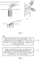
- FIG. 5 different traveling paths may be planned based on different parking spot types.
- (a) in FIG. 5 shows a vertical parking spot
- (b) in FIG. 5 shows an oblique parking spot
- (c) in FIG. 5 shows a horizontal parking spot.
- FIG. 5 is an example for description, and an initial parking pose and a location of a parking spot are not limited in this application.
- the path planning method shown in FIG. 6 may be performed by the vehicle shown in FIG. 1 or the autonomous driving system shown in FIG. 2 .
- the method shown in FIG. 6 includes steps 510 and 520. The following separately details these steps.
- Step 510 Obtain information about an initial parking pose, a target parking pose, and an intermediate pose of a vehicle.
- the vehicle When the vehicle is in the intermediate pose, at least a part of the vehicle is located outside a parking spot in which the target parking pose is located.
- the intermediate pose is a pose other than the initial parking pose and the target parking pose.
- the vehicle is in the intermediate pose, at least a part of the vehicle is located outside the parking spot, and this may mean: The vehicle is located entirely outside the parking spot, or a part of the vehicle is located outside the parking spot and the other part of the vehicle is located inside the parking spot.
- the information about the initial parking pose may refer to a horizontal coordinate and a vertical coordinate of a rear axle center and a heading angle of the vehicle when the vehicle is initially parked.
- the target parking pose may refer to a horizontal coordinate and a vertical coordinate of the rear axle center and a heading angle of the vehicle when the vehicle successfully travels to the parking spot.
- Step 520 Perform segmented planning on a path between the initial parking pose and the target parking pose based on the intermediate pose to obtain a target traveling path.
- the target traveling path may be used by the vehicle to travel from the initial parking pose to the target parking pose.
- segmented planning may be performed on the global path between the initial parking pose and the target parking pose based on the intermediate pose, to obtain segmented traveling tracks, and the target traveling path may be obtained by splicing the segmented traveling tracks.
- the target traveling path may include a first section of traveling path and a second section of traveling path.
- the vehicle is capable of directly traveling to the target parking pose from an intersection point of the first section of traveling path and the second section of traveling path.
- Directly traveling to the target parking pose may mean: The vehicle travels, without stopping, to the target parking pose by adjusting a steering wheel angle of the vehicle.
- the vehicle is capable of directly traveling to the target parking pose from the intersection point of the first section of traveling path and the second section of traveling path.
- the intersection point of the first section of traveling path and the second section of traveling path may refer to the intermediate pose.
- the following describes a plurality of possible implementations of performing segmented path planning based on the intermediate pose.
- the intermediate pose is a vehicle pose in which the vehicle is capable of directly traveling out of the parking spot at a maximum steering wheel angle.
- the intermediate pose may be a vehicle pose in which the vehicle is capable of leaving the parking spot. In other words, by using this pose, the vehicle is capable of directly traveling to the target parking pose in the parking spot.
- the intermediate pose may mean that the vehicle adjusts the steering wheel angle so that the vehicle does not collide with a boundary point of the parking spot.
- the intermediate pose may mean that the vehicle adjusts the steering wheel angle so that the vehicle does not collide with a left boundary point or a right boundary point of the parking spot.
- the intermediate pose may mean that a front corner of the vehicle is higher than a boundary point of the horizontal parking spot so that the vehicle does not collide with the parking spot.
- the intermediate pose may be a pose in which the vehicle is capable of traveling out of the parking spot and does not collide with the parking spot or other vehicles.
- segmented planning is successfully performed between the initial parking pose and the target parking pose of the vehicle to obtain the target traveling path.
- path planning is performed by using the initial parking pose as a planning start point and using the intermediate pose as a planning end point, to obtain the first section of traveling path; and path planning is performed by using the intermediate pose as a planning start point and using the target parking pose as a planning end point, to obtain the second section of traveling path, where the first section of traveling path and the second section of traveling path form the target traveling path.
- a preconfigured vehicle pose may be selected as the intermediate pose.
- the preconfigured vehicle pose may be a preconfigured vehicle pose obtained based on length information and/or width information of the parking spot.
- the preconfigured vehicle pose may be referred to as a heuristic pose.
- the vehicle may be located entirely or partially outside the parking spot when the vehicle is in the heuristic pose.
- the failure of segmented path planning may mean that a distance of the target traveling path obtained by performing segmented planning by using, as the intermediate pose, the vehicle pose in which the vehicle is capable of traveling out of the parking spot at the maximum steering wheel angle is excessively long, or there are a large quantity of direction switching points in a switching direction, causing poor experience of a driver.
- path planning may be performed based on the preconfigured vehicle pose to obtain the target traveling path.
- path planning is performed by using the initial parking pose as a planning start point and using the preconfigured vehicle pose as a planning end point, to obtain the first section of traveling path; and path planning is performed by using the preconfigured vehicle pose as a planning start point and using the target parking pose as a planning end point, to obtain the second section of traveling path, where the first section of traveling path and the second section of traveling path form the target traveling path.
- the heuristic pose may be a forward heuristic pose or a vertical heuristic pose.
- the vehicle is capable of directly traveling to the parking spot by using the forward heuristic pose or the vertical heuristic pose.
- the heuristic pose may be a heuristic pose shown in the figure, and the vehicle is capable of directly traveling to the parking spot by using the heuristic pose.
- the implementation in the case 1 may be preferentially used to perform segmented path planning, and when the planning fails, the case 2 is then used to perform segmented path planning, to ensure that the vehicle is capable of successfully traveling to the parking spot, thereby improving a success rate of automatic parking of the vehicle.
- the preconfigured vehicle pose namely, a heuristic pose
- the vehicle may first travel to the heuristic pose, and then the vehicle may directly travel from the heuristic pose to the parking spot.
- the preconfigured vehicle pose may be obtained through preconfiguration performed based on length information and width information of the parking spot in which the target parking pose is located.
- a vehicle pose in which the vehicle collides with the obstacle or a vehicle pose in the switching direction may be configured as an updated preconfigured vehicle pose.
- the collision pose or the vehicle pose in the switching direction may be configured as an updated heuristic pose.
- the updated heuristic pose may be a new heuristic pose.
- the updated heuristic pose may be a new heuristic pose.
- different target traveling paths may be planned for the vehicle in the automatic parking scenario, and segmented planning may be performed on the global path between the initial parking pose and the target parking pose based on the intermediate pose, to ensure that the vehicle is capable of successfully traveling to the parking spot, thereby improving a success rate of automatic parking of the vehicle.
- the performing segmented planning on a path between the initial parking pose and the target parking pose based on the intermediate pose to obtain a target path includes: using the initial parking pose as a planning start point and using the intermediate pose as a planning end point, to obtain the first section of traveling path; using the intermediate pose as a planning start point and using the initial parking pose as a planning end point, to obtain the second section of traveling path; and obtaining the target traveling path based on the first section of traveling path and the second section of traveling path.
- input parameters of the vehicle may be constrained, so that the input parameters of the vehicle satisfy a dynamics characteristic of the vehicle, thereby improving user experience.
- input parameters of the vehicle on the first section of traveling path and/or the second section of traveling path satisfy a preset threshold, where the input parameters include a speed and the steering wheel angle of the vehicle.
- the input parameters may be constrained, so that a generated same-direction track curvature gradually changes, and an actual characteristic constraint on the vehicle is satisfied. This is conducive to vehicle tracking, thereby improving user experience of a driver or a passenger.
- the preset threshold that the input parameters satisfy may be determined based on a change rate of the steering wheel angle of the vehicle and/or a change rate of a wheel angle of the vehicle.
- the input parameters may be constrained based on a change rate of a front wheel angle and the change rate of the steering wheel angle.
- the input parameters may be constrained based on the front wheel angle.
- the vehicle may be controlled to travel to the target parking pose based on the target traveling path.
- the information about the intermediate pose other than the initial parking pose and the target parking pose is obtained, and segmented planning may be performed on the path between the initial parking pose and the target parking pose based on the intermediate pose.
- segmented planning may be performed on the path between the initial parking pose and the target parking pose based on the intermediate pose.
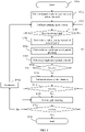
- FIG. 7 is a schematic flowchart of a path planning method according to an embodiment of this application.
- the path planning method 600 shown in FIG. 7 includes steps 610 to 640. The following separately details these steps.
- Step 610 Detect a first operation used by a user to indicate to enable automatic parking.
- Step 620 Display location information of a candidate parking spot on a display in response to the first operation.
- HMI interface for example, a display
- the first operation used by the user to indicate to enable automatic parking may include: pressing an automatic parking button in the vehicle by the user, carrying out an action by the user for indicating, by using a voice, the vehicle to perform automatic parking, or carrying out another action by the user for indicating the vehicle to perform automatic parking.
- Step 630 Detect a second operation of the user for indicating a target parking spot in the candidate parking spot.
- the second operation used by the user to indicate the target parking spot in the candidate parking spot may include: tapping the target parking spot on the HMI interface by the user, carrying out an action by the user for indicating the target parking spot in the candidate parking spot by using a voice, or carrying out another action by the user for indicating the target parking spot in the candidate parking spot.
- Step 640 Display a target traveling path on the display in response to the second operation.
- the target traveling path is used by the vehicle to travel from an initial parking pose indicating automatic parking enabling to a target parking pose in the target parking spot, the target traveling path is obtained by performing segmented planning on a path between the initial parking pose and the target parking pose based on an intermediate pose of the vehicle, and when the vehicle is in the intermediate pose, at least a part of the vehicle is located outside the target parking spot.
- the target traveling path may be obtained according to the path planning method shown in FIG. 6 .
- the vehicle may obtain a track and reference inputs of the vehicle based on the target traveling path, and obtain an actual gear (for example, forward or backward), and an input of a throttle, a brake, a steering wheel angle, or the like of the vehicle by using an algorithm, to control vehicle automatic parking.
- an actual gear for example, forward or backward
- the intermediate pose is a vehicle pose in which the vehicle is capable of traveling out of the target parking spot at a maximum steering wheel angle.
- the target traveling path is obtained by performing planning based on a preconfigured vehicle pose when the segmented planning performed based on the intermediate pose fails, and the preconfigured vehicle pose is obtained based on length information and width information of the target parking spot.
- the intermediate pose is a vehicle pose that is preconfigured based on length information and width information of the parking spot.
- a collision pose of the vehicle or a vehicle pose in a switching direction is configured as an updated preconfigured vehicle pose.
- the target traveling path includes a first section of traveling path and a second section of traveling path, where the first section of traveling path is obtained by performing path planning by using the initial parking pose as a planning start point and using the intermediate pose as a planning end point, and the second section of traveling path is obtained by performing path planning by using the intermediate pose as a planning start point and using the target parking pose as a planning end point.
- input parameters of the vehicle on the first section of traveling path and/or the second section of traveling path satisfy a preset threshold, where the input parameters include a speed and the steering wheel angle of the vehicle.
- the information about the intermediate pose other than the initial parking pose and the target parking pose is obtained, and segmented planning may be performed on the path between the initial parking pose and the target parking pose based on the intermediate pose.
- segmented planning may be performed on the path between the initial parking pose and the target parking pose based on the intermediate pose.
- FIG. 8 is a schematic flowchart of a vehicle path planning method according to an embodiment of this application. The method may be performed by the vehicle shown in FIG. 1 or the autonomous driving system shown in FIG. 2 . The method shown in FIG. 8 includes steps 701 to 714. The following separately details these steps.
- Step 701 Start. To be specific, a vehicle enables an automatic parking mode.
- Step 702 Sense information about a parking spot and an obstacle.
- a sensing system in the vehicle may detect a surrounding environment of the vehicle, to obtain the information about the obstacle and the parking spot, such as a location of the obstacle, a length of the parking spot, and a width of the parking spot.
- an automatic parking system may prompt a driver to limit a speed to a small value and to drive slowly through the parking spot, thereby improving detection precision of the surrounding environment.
- Step 703 Perform a parking space search (that is, a parking spot search).
- the automatic parking system may perform preliminary screening based on information such as the length, a width, a distance, and a type of the parking spot (for example, including a vertical parking spot, a parallel parking spot, or a vertical parking spot). If the parking spot satisfies a corresponding requirement, step S704 is performed.
- Step 704 Select a parking spot.
- the automatic parking system may summarize the information about the parking spot, and feed back and display the information about the parking spot on a central control HMI interface of the vehicle by integrating images of the fisheye camera.
- the vehicle parking system prompts the driver to select an intended parking spot.
- Step 705 Determine a path planning start point and end point.
- the automatic parking system may determine poses of a parking start point and a parking end point based on the parking spot selected by the driver, and start to generate a planned track in a parking scenario.
- Step 706 Perform hierarchical optimized partial planning.
- the automatic parking system may first attempt to perform partial planning, and classify the planned track into two layers: a trapping relief layer and a direct layer.
- the trapping relief layer means that the vehicle in the parking spot is more constrained by a boundary of the parking spot.
- the direct layer means that the vehicle is less constrained than in the trapping relief layer. An intersection point of the trapping relief layer and the direct layer allows the vehicle to directly travel out of the parking spot.
- FIG. 9 is a schematic diagram of a trapping relief layer and a direct layer in hierarchical planning according to an embodiment of this application.
- a principle of parking in a horizontal parking spot is similar to that of parking in a vertical parking spot, but a configured pose in the horizontal parking spot when the vehicle travels out leftward or rightward may be different from that in the vertical parking spot.
- a configured target pose may be expressed as a formula (1).
- a trapping relief layer in a vertical parking spot is used to increase a heading angle of the vehicle until a corner of a vehicle head is higher than a parking boundary.
- a configured target pose may be expressed as a formula (2).
- a trapping relief layer in an oblique parking spot is used to enable the vehicle to go straight until the vehicle reaches a location (x>x set ) at which the vehicle is capable of directly traveling out of a vertical parking spot at a maximum angle (either leftward or rightward).
- a configured target pose may be expressed as a formula (3).
- an initial parking pose of the vehicle may be configured as the target pose, that is, the initial parking pose shown in FIG. 6 .
- a target parking pose of the vehicle to the initial parking pose of the vehicle may be planned in FIG. 9 . If the vehicle can safely travel from the parking spot to the initial parking pose, the vehicle can also travel from the initial parking pose to the target parking pose in the path.
- a target traveling path on which the vehicle travels to the parking spot may be obtained through backward reasoning by using a target traveling path on which the vehicle travels out of the parking spot.
- a vehicle pose at the intersection point of the trapping relief layer and the direct layer is determined more easily based on a size of the vehicle and a size of the parking spot when the path on which the vehicle travels out of the parking spot is planned. This simplifies a path planning procedure.
- Step 707 Perform a single-step optimal solution.
- the track is discretely solved at the trapping relief layer or the direct layer.
- a nonlinear optimal solution may be performed in each single step according to vehicle dynamics, and discrete tracks obtained by using single-step solutions are spliced to obtain a final parking track, namely, the target traveling path.
- the single-step optimal solution process may include step 7071 to step 7074.
- q i+1 represents a vehicle state at a moment (i+1); x i+1 and y i+1 represent a horizontal coordinate and a vertical coordinate of a rear axle center of the vehicle, respectively; ⁇ i+1 represents a heading angle of the vehicle; D i represents a traveling direction of the vehicle at a moment i, where D i ⁇ ⁇ -1, 1 ⁇ ; it indicates that the vehicle travels forward when D i is 1, and it indicates that the vehicle is reversed when D i is
- u may represent a function relationship between a speed and the steering wheel angle of the vehicle.
- Step 7073 During single-step optimization, input parameters need to be constrained, and that the vehicle does not collide with the obstacle needs to be ensured.
- s min represents a distance traveled in a time interval based on a minimum speed limit of the vehicle
- s max represents a distance traveled in a time interval based on a maximum speed limit of the vehicle
- u i needs to be constrained by a change rate of a front wheel angle and a change rate of the steering wheel angle, and needs to satisfy constraints shown in formulas (9) and (10).
- T s represents a discrete time interval
- ⁇ max represents a maximum change rate of the steering wheel angle
- ⁇ max represents a maximum steering wheel angle
- the collision constraint is related to a shape and a location of the obstacle that are obtained by the sensing system.
- a Minkowski difference between a contour of the vehicle and the obstacle at a next moment may be checked to determine whether an origin is included.
- the origin may be an origin of a coordinate system, and the coordinate system may be a coordinate system relative to the parking spot. If the origin is included, it indicates that a collision may occur in this pose.
- the formula (12) is the iterative equation in step 6071, the formula (13) represents the collision constraint in step 7073, and the formula (14) represents the input parameter constraint in step 7073.
- Step 708 Determine whether the partial planning succeeds, and if the partial planning succeeds, perform step 709; or if the partial planning fails, perform step 710.
- step 710 is performed for heuristic global planning.
- FIG. 10A and FIG. 10B For a schematic flowchart of the partial planning, refer to FIG. 10A and FIG. 10B . The following details the procedure for the partial planning.
- Step 709 Perform path tracking.
- planned paths for the trapping relief layer and the direct layer may be separately solved, and a target traveling track may be obtained by splicing the two planned paths.
- the automatic parking system controls, by using the tracking control module 430 shown in FIG. 4 , the vehicle to travel based on the target traveling track.
- Step 710 When the hierarchical partial planning fails, perform heuristic global planning.
- a failure of the hierarchical partial planning may mean that a condition 1 and/or a condition 2 are/is satisfied.
- Condition 2 There are an excessive quantity of planned direction switching points, that is, a quantity of points of D i ⁇ D i +1 is greater than a threshold.
- heuristic planning may be performed to improve a success rate of automatic parking.
- FIG. 11 For a schematic flowchart of the heuristic global planning, refer to FIG. 11 . The following details the procedure for the partial planning.
- Step 711 Determine whether the heuristic path planning succeeds, and if the heuristic path planning succeeds, perform step 709; or if the heuristic path planning fails, go back to perform step 703.
- Step 712 Determine whether the vehicle successfully performs path tracking, and if the path tracking succeeds, perform step 713; or if the path tracking fails, perform step 714 to backtrack, and perform step 703 again to perform a parking spot search.
- Step 713 End the path planning for the automatic parking system.
- FIG. 8 As an example are intended to help a person skilled in the art understand embodiments of this application, but not to limit embodiments of this application to the illustrated specific values or specific scenarios. It is clear that a person skilled in the art can make various equivalent modifications or variations based on the given example, and these modifications or variations also fall within the scope of embodiments of this application.
- FIG. 10A and FIG. 10B are a schematic flowchart of a partial path planning method according to an embodiment of this application. The method may be performed by the vehicle shown in FIG. 1 or the autonomous driving system shown in FIG. 2 .
- FIG. 10A and FIG. 10B may be a flowchart of partial planning in which the hierarchical optimized partial planning in step 706 shown in FIG. 8 is combined with the single-step optimal solution in step 707 shown in FIG. 8 .
- the method shown in FIG. 10A and FIG. 10B includes steps 801 to 814. The following separately details these steps.
- Step 801 Configure a target parking pose as an ego-pose.
- Step 802 Determine whether a deviation between a current vehicle pose and an initial parking pose of a vehicle is less than a threshold, and if the deviation is less than the threshold, perform step 803; or if the deviation is greater than the threshold, perform step 804.
- the target parking pose of the vehicle to the initial parking pose of the vehicle may be planned.
- planning may be performed by using the target parking pose as a planning start point and using the initial parking pose as a planning end point. If the deviation between the current vehicle pose and the initial parking pose is less than the threshold, it may indicate that a planned path enables the vehicle to successfully travel out of a parking spot. Likewise, the planned path also enables the vehicle to travel from the initial parking pose to the parking spot.
- Step 803 The planning succeeds.
- a parking path may be stored, and then a system performs operations, so that the vehicle starts path tracking.
- Step 804 Configure a target pose based on a parking spot type.
- the deviation between the current vehicle pose and the initial parking pose of the vehicle is greater than the threshold, it indicates that the vehicle path planning fails. In this case, a parking spot search may need to be performed again, and the target pose is configured based on the selected parking spot type.
- target poses for different parking spot types are shown in FIG. 9 .
- the trapping relief layer in the vertical parking spot is used to increase a heading angle of the vehicle until a corner of a vehicle head is higher than a boundary of the parking spot.
- a configured target pose may be expressed as the foregoing formula (2).
- the trapping relief layer in the oblique parking spot is used to enable the vehicle to go straight until the vehicle reaches a location (x>x set ) at which the vehicle is capable of directly traveling out of a vertical parking spot at a maximum angle (either leftward or rightward).
- a configured target pose may be expressed as the foregoing formula (3).
- a principle of parking in the horizontal parking spot is similar to that of parking in a vertical parking spot, but a configured pose in the horizontal parking spot when the vehicle travels out leftward or rightward may be different from that in the vertical parking spot.
- a configured target pose may be expressed as the foregoing formula (1).
- Step 805 Determine whether to switch a planning layer, and if the planning layer needs to be switched, perform step 806; or if the planning layer does not need to be switched, perform step 807.
- whether the vehicle is at the trapping relief layer or the direct layer shown in FIG. 9 may be determined based on the current pose of the vehicle. Target poses of the vehicle are different for the different layers.
- Step 806 Switch the planning layer from the trapping relief layer to the direct layer.
- Step 807 Determine an external obstacle constraint and an input parameter constraint.
- step 7071 to step 7074 in FIG. 8 that is, refer to the foregoing formula (4) to the foregoing formula (14).
- Step 808 Initialize a cost function.
- the cost function may be shown in the foregoing formula (6) in step 7072 in FIG. 8 . Details are not described herein again.
- Step 809 Perform nonlinear optimization on the cost function.
- nonlinear optimization process may be shown in the foregoing formula (9) and the foregoing formula (10) in step 7073 in FIG. 8 . Details are not described herein again.
- Step 810 Determine whether the cost function is critical or whether a collision is unavoidable, and if the cost function is critical or a collision is unavoidable, perform step 811 to change a parking direction; otherwise, perform step 812.
- Step 811 Change the parking direction.
- the parking direction of the vehicle may be changed.
- policies for changing a traveling direction are different for the trapping relief layer and the direct layer.
- the direction needs to be changed.
- the direction and the cost function need to be changed.
- Nonlinear optimization is performed to keep the cost function declining, so that there can be an exploration capability in one direction for the planning and falling into a state of oscillation can be avoided.
- the direction is changed when a formula (15) is satisfied, where l min represents a minimum cost for the direction and the stage, as shown in a formula (16).
- Step 812 Output a vehicle pose at a next moment.
- a vehicle pose at a moment i obtained through planning in step 807 to step 809 satisfies the external obstacle constraint and the input parameter constraint
- a vehicle pose at the next moment namely, a moment (i+1)
- Step 813 Determine whether a planned distance is excessively long or there are an excessive quantity of planned direction switching points, and if the planned distance is excessively long or there are an excessive quantity of planned direction switching points, perform step 814, that is, the planning fails; otherwise, perform step 802.
- heuristic global planning may be performed when the hierarchical partial planning fails.
- a heuristic pose for parking the vehicle needs to be selected based on a type and a size of the parking spot. The following details a procedure for a heuristic path planning method with reference to FIG. 11 .
- FIG. 11 is a schematic flowchart of a heuristic path planning method according to an embodiment of this application. The method may be performed by the vehicle shown in FIG. 1 or the autonomous driving system shown in FIG. 2 . The method shown in FIG. 11 includes steps 901 to 910. The following separately details these steps.
- Step 901 Start.
- Step 902 Perform hierarchical partial planning from a target parking pose to an initial parking pose, that is, perform the hierarchical partial planning method shown in FIG. 10A and FIG. 10B .
- Step 903 Determine whether the hierarchical partial planning succeeds, and if the partial planning succeeds, perform step 904, that is, end the path planning; or if the partial planning fails, perform step 905.
- Step 905 Select a vehicle pose q min with a minimum cost function value from a heuristic pose list.
- a heuristic pose selected for the first time may be obtained through configuration performed based on an actual width and length of a parking spot. If planning performed from the heuristic pose selected for the first time to the target parking pose fails, for example, if a vehicle in the heuristic pose selected for the first time collides with an obstacle, heuristic pose reselection is performed. Heuristic pose reselection may be performed based on the heuristic pose list, and the vehicle pose with the minimum cost function value is selected from the heuristic pose list.
- a heuristic pose included in the heuristic pose list may be a pose selected before heuristic pose selection is performed this time, and path planning performed from this pose to the target parking pose fails.
- H(q) may be an estimated cost of this pose and a Euclidean distance may be used; rs and r sw may represent a distance coefficient and a direction switching point coefficient, respectively; S H may represent a distance from a parking pose to this pose; and N sw may represent a quantity of direction switching points.
- Step 906 Generate a heuristic pose 1q h1 and a heuristic pose 2q h2 based on the vehicle pose q min .
- the heuristic pose 1q h1 and/or the heuristic pose 2q h2 may be selected based on the vehicle pose q min and experience.
- the heuristic pose 1q h1 and the heuristic pose 2q h2 can be successfully planned is indefinite. Because an environment of an obstacle around the vehicle is continuously updated in real time, the heuristic pose 1q h1 and the heuristic pose 2q h2 may be configured based on a previous surrounding environment of the vehicle.
- Step 907 Perform partial planning 1: perform planning from the vehicle pose q min to the heuristic pose 1q h1 and from the vehicle pose q min to the heuristic pose 2q h2 . If the partial planning succeeds, perform step 908. If the planning fails, for example, if the vehicle in the heuristic pose 1q h1 or the heuristic pose 2q h2 collides with an obstacle, perform step 908 based on a collision pose of the vehicle.
- Step 908 Perform partial planning 2: perform path planning by using the heuristic poses obtained through successful planning in step 907 or the collision pose as a planning start point and using the initial parking pose q s as a planning end point.
- Step 909 Determine whether the partial planning succeeds, and if the planning succeeds, perform step 904, that is, end the path planning; or if the planning fails, perform step 910.
- Step 910 Add the vehicle pose on which the planning fails and a vehicle pose in a switching direction in step 907 to the heuristic pose list, and calculate cost functions of the vehicle poses according to the formula (17).
- a cost function of the heuristic pose may be multiplied by a coefficient greater than 1, so that the heuristic pose is not preferentially selected when a new heuristic pose is selected next time.
- FIG. 12 is a schematic diagram of a heuristic pose according to an embodiment of this application.
- heuristic poses in the vertical parking spot may include the forward heuristic pose and the vertical heuristic pose.
- the heuristic pose shown in (b) in FIG. 12 may be used.
- FIG. 12 is an example for describing the heuristic pose.
- the vehicle may be located entirely outside the parking spot when the vehicle is in the heuristic pose, or a part of the vehicle may be located outside the parking spot when the vehicle is in the heuristic pose. This is not limited in this application.
- a vehicle pose that is near the heuristic pose and in which the vehicle does not collide with the obstacle may be configured as an updated heuristic pose.
- FIG. 13 is a schematic diagram of generating an updated heuristic pose according to an embodiment of this application.
- vehicle path planning apparatuses in embodiments of this application may perform various path planning methods in the foregoing embodiments of this application.
- for detailed working processes of the following products refer to corresponding processes in the foregoing method embodiments.
- FIG. 14 is a schematic block diagram of a vehicle path planning apparatus according to an embodiment of this application. It should be understood that the path planning apparatus 1000 may perform the path planning methods shown in FIG. 6 and FIG. 8 to (b) in FIG. 13 .
- the path planning apparatus 1000 includes an obtaining unit 1010 and a processing unit 1020.
- the obtaining unit 1010 is configured to obtain information about an initial parking pose, a target parking pose, and an intermediate pose of a vehicle, where when the vehicle is in the intermediate pose, at least a part of the vehicle is located outside a parking spot in which the target parking pose is located.
- the processing unit 1020 is configured to perform segmented planning on a path between the initial parking pose and the target parking pose based on the intermediate pose to obtain a target traveling path, where the target traveling path is used by the vehicle to travel from the initial parking pose to the target parking pose.
- the intermediate pose is a vehicle pose in which the vehicle is capable of traveling out of the parking spot at a maximum steering wheel angle.
- the processing unit 1020 is specifically configured to: when the segmented planning performed based on the intermediate pose fails, perform path planning based on a vehicle pose that is preconfigured based on length information and width information of the parking spot, to obtain the target traveling path.
- the intermediate pose is a vehicle pose that is preconfigured based on length information and width information of the parking spot.
- a collision pose of the vehicle is configured as an updated preconfigured vehicle pose.
- processing unit 1020 is specifically configured to:
- input parameters of the vehicle on the first section of traveling path and/or the second section of traveling path satisfy a preset threshold, where the input parameters include a speed and a steering wheel angle of the vehicle.
- FIG. 15 is a schematic block diagram of a vehicle path planning apparatus according to an embodiment of this application. It should be understood that the path planning apparatus 1100 may perform the path planning methods shown in FIG. 7 to (b) in FIG. 13 .
- the path planning apparatus 1100 includes a detection unit 1110 and a processing unit 1120.
- the detection unit 1110 is configured to detect a first operation used by a user to instruct to enable automatic parking.
- the processing unit 1120 is configured to display location information of a candidate parking spot on a display in response to the first operation.
- the detection unit 1110 is further configured to detect a second operation of the user for indicating a target parking spot in the candidate parking spot.
- the processing unit 1120 is further configured to display a target traveling path on the display in response to the second operation, where the target traveling path is used by a vehicle to travel from an initial parking pose indicating automatic parking enabling to a target parking pose in the target parking spot, the target traveling path is obtained by performing segmented planning on a path between the initial parking pose and the target parking pose based on an intermediate pose of the vehicle, and when the vehicle is in the intermediate pose, at least a part of the vehicle is located outside the target parking spot.
- the intermediate pose is a vehicle pose in which the vehicle is capable of traveling out of the parking spot at a maximum steering wheel angle.
- the processing unit 1120 is specifically configured to: when the segmented planning performed based on the intermediate pose fails, perform path planning based on a vehicle pose that is preconfigured based on length information and width information of the parking spot, to obtain the target traveling path.
- the intermediate pose is a vehicle pose that is preconfigured based on length information and width information of the parking spot.
- a collision pose of the vehicle is configured as an updated preconfigured vehicle pose.
- the target traveling path includes a first section of traveling path and a second section of traveling path, where the first section of traveling path is obtained by performing path planning by using the initial parking pose as a planning start point and using the intermediate pose as a planning end point, and the second section of traveling path is obtained by performing path planning by using the intermediate pose as a planning start point and using the target parking pose as a planning end point.
- input parameters of the vehicle on the first section of traveling path and/or the second section of traveling path satisfy a preset threshold, where the input parameters include a speed and a steering wheel angle of the vehicle.
- path planning apparatus 1000 and the path planning apparatus 1100 are embodied in forms of functional units.
- the term "unit” herein may be implemented in a form of software and/or hardware. This is not specifically limited.
- the "unit” may be a software program, a hardware circuit, or a combination thereof for implementing the foregoing function.
- the hardware circuit may include an application-specific integrated circuit (application specific integrated circuit, ASIC), an electronic circuit, a processor (for example, a shared processor, a dedicated processor, or a group processor) configured to execute one or more software or firmware programs, a memory, a merged logic circuit, and/or another appropriate component that supports the described function.
- ASIC application specific integrated circuit
- ASIC application specific integrated circuit
- a processor for example, a shared processor, a dedicated processor, or a group processor configured to execute one or more software or firmware programs, a memory, a merged logic circuit, and/or another appropriate component that supports the described function.
- the units in the examples described in this embodiment of this application can be implemented by electronic hardware or a combination of computer software and electronic hardware. Whether the functions are executed by hardware or software depends on particular applications and design constraints of the technical solutions. A person skilled in the art may use a different method to implement the described functions for each particular application, but it should not be considered that the implementation goes beyond the scope of this application.
- FIG. 16 is a schematic diagram of a structure of hardware of a vehicle path planning apparatus according to an embodiment of this application.
- the path planning apparatus 1200 (the path planning apparatus 1200 may be specifically a computer device) includes a memory 1201, a processor 1202, a communications interface 1203, and a bus 1204. Communication connections are implemented between the memory 1201, the processor 1202, and the communications interface 1203 through the bus 1204.
- the memory 1201 may be a read-only memory (read only memory, ROM), a static storage device, a dynamic storage device, or a random access memory (random access memory, RAM).
- the memory 1201 may store a program.
- the processor 1202 is configured to perform the steps of the path planning methods in embodiments of this application, for example, perform the steps shown in FIG. 6 to (b) in FIG. 13 .
- the path planning apparatus shown in this embodiment of this application may be a server.
- the apparatus may be a cloud server, or may be a chip configured in a cloud server.
- the processor 1202 may be a general-purpose central processing unit (central processing unit, CPU), a microprocessor, an application-specific integrated circuit (application specific integrated circuit, ASIC), or one or more integrated circuits, configured to execute a related program to implement the path planning methods in embodiments of this application.
- CPU central processing unit
- ASIC application specific integrated circuit
- the processor 1202 may alternatively be an integrated circuit chip and has a signal processing capability.
- the steps of the path planning methods in this application may be completed by using an integrated logic circuit of hardware in the processor 1202 or instructions in a software form.
- the processor 1202 may be a general-purpose processor, a digital signal processor (digital signal processing, DSP), an application-specific integrated circuit (ASIC), a field programmable gate array (field programmable gate array, FPGA), another programmable logic device, a discrete gate, a transistor logic device, or a discrete hardware component.
- the processor 1202 may implement or perform the methods, the steps, and the logical block diagrams that are disclosed in embodiments of this application.
- the general-purpose processor may be a microprocessor, or the processor may be any conventional processor or the like. Steps of the methods disclosed with reference to embodiments of this application may be directly implemented by using a hardware decoding processor, or may be implemented by using a combination of hardware in the decoding processor and a software module.
- the software module may be located in a mature storage medium in the art, such as a random access memory, a flash memory, a read-only memory, a programmable read-only memory, an electrically erasable programmable memory, or a register.
- the storage medium is located in the memory 1201.
- the processor 1202 reads information from the memory 1201, and in combination with the hardware in the processor 1202, implements the functions that need to be performed by the units included in the path planning apparatus shown in FIG. 14 or FIG. 15 in embodiments of this application, or performs the path planning methods shown in FIG. 6 to (b) in FIG. 13 in the method embodiments of this application.
- the communications interface 1203 implements communication between the path planning apparatus 1200 and another device or a communications network by using a transceiver apparatus, for example, but not limited to, a transceiver.
- the bus 1204 may include a path on which information is transmitted between components (for example, the memory 1201, the processor 1202, and the communications interface 1203) of the path planning apparatus 1200.
- path planning apparatus 1200 merely shows the memory, the processor, and the communications interface. However, in a specific implementation process, a person skilled in the art should understand that the path planning apparatus 1200 may further include other components necessary to implement normal running. In addition, a person skilled in the art should understand that, according to a specific requirement, the path planning apparatus 1200 may further include hardware components for implementing other additional functions.
- path planning apparatus 1200 may alternatively include only the components necessary to implement embodiments of this application, and unnecessarily includes all the components shown in FIG. 16 .
- sequence numbers of the foregoing processes do not mean execution sequences in various embodiments of this application.
- the execution sequences of the processes should be determined based on functions and internal logic of the processes, and should not be construed as any limitation on the implementation processes of embodiments of this application.
- the disclosed systems, apparatuses, and methods may be implemented in another manner.
- the described apparatus embodiments are merely examples.
- the unit division is merely logical function division and may be other division in actual implementation.
- a plurality of units or components may be combined or integrated into another system, or some features may be ignored or not be performed.
- the displayed or discussed mutual couplings or direct couplings or communication connections may be implemented through some interfaces.
- the indirect couplings or communication connections between the apparatuses or units may be implemented in electrical, mechanical, or other forms.
- the units described as separate parts may or may not be physically separate, and parts displayed as units may or may not be physical units, may be located in one position, or may be distributed on a plurality of network units. Some or all of the units may be selected according to an actual requirement to achieve the objectives of the solutions of embodiments.
- the functions When the functions are implemented in a form of a software functional unit and sold or used as an independent product, the functions may be stored in a computer-readable storage medium. Based on such an understanding, the technical solutions of this application essentially, or the part contributing to the conventional technology, or some of the technical solutions may be implemented in a form of a software product.
- the computer software product is stored in a storage medium, and includes several instructions for instructing a computer device (which may be a personal computer, a server, a network device, or the like) to perform all or some of the steps of the methods described in embodiments of this application.
- the foregoing storage medium includes: any medium that can store program code, such as a USB flash drive, a removable hard disk, a read-only memory (read-only memory, ROM), a random access memory (random access memory, RAM), a magnetic disk, or an optical disc.
- program code such as a USB flash drive, a removable hard disk, a read-only memory (read-only memory, ROM), a random access memory (random access memory, RAM), a magnetic disk, or an optical disc.
Landscapes
- Engineering & Computer Science (AREA)
- Radar, Positioning & Navigation (AREA)
- Remote Sensing (AREA)
- Automation & Control Theory (AREA)
- Physics & Mathematics (AREA)
- General Physics & Mathematics (AREA)
- Transportation (AREA)
- Mechanical Engineering (AREA)
- Human Computer Interaction (AREA)
- Chemical & Material Sciences (AREA)
- Combustion & Propulsion (AREA)
- Control Of Driving Devices And Active Controlling Of Vehicle (AREA)
- Traffic Control Systems (AREA)
Applications Claiming Priority (1)
| Application Number | Priority Date | Filing Date | Title |
|---|---|---|---|
| PCT/CN2019/122097 WO2021102955A1 (fr) | 2019-11-29 | 2019-11-29 | Procédé et appareil de planification de trajet pour véhicule |
Publications (2)
| Publication Number | Publication Date |
|---|---|
| EP4067821A1 true EP4067821A1 (fr) | 2022-10-05 |
| EP4067821A4 EP4067821A4 (fr) | 2023-04-05 |
Family
ID=75541313
Family Applications (1)
| Application Number | Title | Priority Date | Filing Date |
|---|---|---|---|
| EP19954320.8A Withdrawn EP4067821A4 (fr) | 2019-11-29 | 2019-11-29 | Procédé et appareil de planification de trajet pour véhicule |
Country Status (3)
| Country | Link |
|---|---|
| EP (1) | EP4067821A4 (fr) |
| CN (1) | CN112714729A (fr) |
| WO (1) | WO2021102955A1 (fr) |
Families Citing this family (37)
| Publication number | Priority date | Publication date | Assignee | Title |
|---|---|---|---|---|
| CN115273523A (zh) * | 2021-04-29 | 2022-11-01 | 欧特明电子股份有限公司 | 识别停车位的方法及系统 |
| CN113212424B (zh) * | 2021-05-24 | 2022-10-11 | 郑州睿行汽车科技有限公司 | 一种车辆及其自动泊车方法和装置 |
| US12099371B2 (en) * | 2021-06-04 | 2024-09-24 | Ubkang (Qingdao) Technology Co., Ltd. | Fast continuous regulation of nonholonomic mobile robots |
| EP4130922B1 (fr) * | 2021-08-02 | 2025-06-18 | Nio Technology (Anhui) Co., Ltd | Procédé et système de positionnement de véhicule pour un scénario de stationnement fixe |
| CN113525357B (zh) * | 2021-08-25 | 2022-12-09 | 吉林大学 | 自动泊车决策模型优化系统及方法 |
| EP4385844A4 (fr) * | 2021-08-30 | 2024-10-23 | Huawei Technologies Co., Ltd. | Procédé et appareil de stationnement automatique et véhicule |
| CN113848898B (zh) * | 2021-09-17 | 2025-01-10 | 京东鲲鹏(江苏)科技有限公司 | 路径规划方法、装置、自动驾驶车辆和存储介质 |
| CN113734202B (zh) * | 2021-09-22 | 2023-12-01 | 驭势科技(北京)有限公司 | 多车协同方法、装置、系统、设备、介质和产品 |
| CN113928341B (zh) * | 2021-11-30 | 2023-05-30 | 广州文远知行科技有限公司 | 一种道路决策方法、系统、设备和介质 |
| CN113830079B (zh) * | 2021-10-19 | 2023-09-01 | 同济大学 | 任意起始位姿的连续曲率泊车路径在线规划方法及系统 |
| CN113985871A (zh) * | 2021-10-21 | 2022-01-28 | 上海欧菲智能车联科技有限公司 | 泊车路径规划方法、泊车路径规划装置、车辆及存储介质 |
| CN114001745B (zh) * | 2021-10-25 | 2023-11-24 | 东南大学 | 一种电动汽车泊车引导系统及其位置检测评价方法 |
| CN114030463B (zh) * | 2021-11-23 | 2024-05-14 | 上海汽车集团股份有限公司 | 一种自动泊车系统的路径规划方法及装置 |
| CN114261399B (zh) * | 2021-11-24 | 2023-11-07 | 吉林大学 | 一种冰雪路面下智能驾驶汽车决策规划方法 |
| CN114312757A (zh) * | 2021-12-22 | 2022-04-12 | 华人运通(上海)自动驾驶科技有限公司 | 一种基于四轮转向的泊车规划方法、车辆 |
| CN114347982B (zh) * | 2021-12-24 | 2024-06-14 | 北京经纬恒润科技股份有限公司 | 用于自动泊车的路径规划方法以及系统 |
| CN114355927B (zh) * | 2021-12-29 | 2023-12-29 | 杭州海康机器人股份有限公司 | 路径规划方法、装置及计算机可读存储介质 |
| CN114852058B (zh) * | 2022-05-11 | 2023-03-31 | 远峰科技股份有限公司 | 自动泊车路径规划方法、装置、系统及可读存储介质 |
| CN115071505B (zh) * | 2022-06-20 | 2024-06-25 | 武汉理工大学 | 燃料电池汽车分层规划方法、系统、装置及存储介质 |
| CN115056766A (zh) * | 2022-06-27 | 2022-09-16 | 重庆长安汽车股份有限公司 | 自动泊车方法、装置、设备以及介质 |
| CN115140090A (zh) * | 2022-06-28 | 2022-10-04 | 禾多科技(北京)有限公司 | 车辆控制方法、装置、电子设备和计算机可读介质 |
| CN115195706B (zh) * | 2022-07-14 | 2025-10-24 | 清华大学 | 一种泊车路径规划方法、装置 |
| CN115285113A (zh) * | 2022-08-30 | 2022-11-04 | 重庆长安汽车股份有限公司 | 一种自动泊车方法及装置、设备和介质 |
| CN115465266B (zh) * | 2022-11-10 | 2023-03-21 | 集度科技有限公司 | 泊车路径规划方法、装置、设备及存储介质 |
| CN115743096B (zh) * | 2022-12-21 | 2026-02-27 | 东风悦享科技有限公司 | 一种基于场景动态识别的多模式泊车路径规划方法、系统及存储介质 |
| CN115871649B (zh) * | 2022-12-22 | 2025-12-02 | 北斗智联科技有限公司 | 一种二次泊车路径规划方法、装置和车辆 |
| CN116215661B (zh) * | 2023-01-31 | 2024-10-25 | 广汽埃安新能源汽车股份有限公司 | 一种车辆的泊车控制方法、装置、车辆及电子设备 |
| CN115996356B (zh) * | 2023-03-23 | 2023-06-16 | 西安航天天绘数据技术有限公司 | 一种区宽通信下机动中心车载路径规划系统及方法 |
| CN116409311A (zh) * | 2023-05-04 | 2023-07-11 | 浙江吉利控股集团有限公司 | 收费站岗亭的行驶控制方法、装置、设备及存储介质 |
| CN116674527A (zh) * | 2023-05-04 | 2023-09-01 | 宇通客车股份有限公司 | 一种自动泊车轨迹生成方法和装置 |
| CN117163068B (zh) * | 2023-09-25 | 2025-05-06 | 杭州海康威视数字技术股份有限公司 | 一种窄道通行方法、装置及车辆 |
| US12594955B2 (en) * | 2023-10-06 | 2026-04-07 | Gm Cruise Holdings Llc | Autonomous vehicle with freespace planner |
| CN120207312A (zh) * | 2023-12-20 | 2025-06-27 | 深圳引望智能技术有限公司 | 泊车方法、装置和车辆 |
| CN120756461A (zh) * | 2024-03-27 | 2025-10-10 | 深圳引望智能技术有限公司 | 一种智能泊车方法及装置 |
| CN120886850A (zh) * | 2024-04-25 | 2025-11-04 | 深圳引望智能技术有限公司 | 智能驾驶的方法和装置 |
| CN119527280B (zh) * | 2024-12-20 | 2025-10-10 | 奇瑞汽车股份有限公司 | 一种自动泊车逆向路径规划方法、装置、设备及介质 |
| CN120003469B (zh) * | 2025-03-17 | 2025-10-21 | 深蓝汽车科技有限公司 | 基于深度强化学习的自动泊车路径规划模型构建方法、装置、设备及车辆 |
Family Cites Families (19)
| Publication number | Priority date | Publication date | Assignee | Title |
|---|---|---|---|---|
| JP2004012425A (ja) * | 2002-06-11 | 2004-01-15 | Matsushita Electric Ind Co Ltd | 情報提供装置 |
| US8065058B2 (en) * | 2004-12-24 | 2011-11-22 | Continental Teves Ag & Co. Ohg | Method for guiding a vehicle into a parking space and parking assistance device |
| JP4906641B2 (ja) * | 2007-09-04 | 2012-03-28 | アルパイン株式会社 | ナビゲーション装置及び情報システム |
| CN103136955B (zh) * | 2011-11-24 | 2016-01-20 | 北京四维图新科技股份有限公司 | 导航方法和导航装置 |
| DE102012015922A1 (de) * | 2012-08-10 | 2014-02-13 | Daimler Ag | Verfahren zum Durchführen eines Parkvorgangs eines Fahrzeugs mittels eines Fahrerassistenzsystems |
| CN103158703B (zh) * | 2013-03-26 | 2016-04-06 | 北京经纬恒润科技有限公司 | 一种平行泊车的控制方法 |
| KR101512784B1 (ko) * | 2013-09-10 | 2015-04-17 | 한양대학교 산학협력단 | 자동주차 지원방법 및 자동주차 지원시스템 |
| CN105539430B (zh) * | 2015-12-29 | 2018-04-03 | 北京理工大学 | 一种基于手持终端的人车交互智能泊车方法 |
| CN105857306B (zh) * | 2016-04-14 | 2018-07-10 | 中国科学院合肥物质科学研究院 | 一种用于多种泊车场景的车辆自主泊车路径规划方法 |
| US9969386B1 (en) * | 2017-01-10 | 2018-05-15 | Mitsubishi Electric Research Laboratories, Inc. | Vehicle automated parking system and method |
| CN108961811B (zh) * | 2017-05-25 | 2020-12-22 | 纵目科技(上海)股份有限公司 | 停车场车辆定位方法、系统、移动终端及存储介质 |
| US11155257B2 (en) * | 2017-06-26 | 2021-10-26 | Hitachi Automotive Systems, Ltd. | Automatic parking control device |
| CN107274716A (zh) * | 2017-08-08 | 2017-10-20 | 重庆邮电大学 | 一种室内外融合导航的停车系统与方法 |
| CN107618503B (zh) * | 2017-08-29 | 2019-07-23 | 广州小鹏汽车科技有限公司 | 一种自动泊车控制方法及系统 |
| CN107776570B (zh) * | 2017-09-19 | 2020-09-01 | 广州汽车集团股份有限公司 | 全自动泊车方法及全自动泊车系统 |
| JP2019064431A (ja) * | 2017-09-29 | 2019-04-25 | パナソニックIpマネジメント株式会社 | 駐車支援装置 |
| CN109398349A (zh) * | 2018-09-11 | 2019-03-01 | 同济大学 | 一种基于几何规划及强化学习的自动泊车方法及系统 |
| CN109606354B (zh) * | 2018-10-18 | 2020-07-28 | 同济大学 | 一种基于分层规划的自动泊车方法及辅助系统 |
| CN109866759B (zh) * | 2019-02-01 | 2020-12-22 | 吉林微思智能科技有限公司 | 一种自动泊车方法 |
-
2019
- 2019-11-29 EP EP19954320.8A patent/EP4067821A4/fr not_active Withdrawn
- 2019-11-29 WO PCT/CN2019/122097 patent/WO2021102955A1/fr not_active Ceased
- 2019-11-29 CN CN201980057207.3A patent/CN112714729A/zh active Pending
Also Published As
| Publication number | Publication date |
|---|---|
| EP4067821A4 (fr) | 2023-04-05 |
| WO2021102955A1 (fr) | 2021-06-03 |
| CN112714729A (zh) | 2021-04-27 |
Similar Documents
| Publication | Publication Date | Title |
|---|---|---|
| EP4067821A1 (fr) | Procédé et appareil de planification de trajet pour véhicule | |
| JP7540641B2 (ja) | 自動運転方法、関連装置及びコンピュータ読み取り可能記憶媒体 | |
| US12061088B2 (en) | Obstacle avoidance method and apparatus | |
| CN110379193B (zh) | 自动驾驶车辆的行为规划方法及行为规划装置 | |
| CN112230642B (zh) | 道路可行驶区域推理方法及装置 | |
| CN113492830B (zh) | 一种车辆泊车路径规划方法及相关设备 | |
| US12409849B2 (en) | Method and apparatus for passing through barrier gate crossbar by vehicle | |
| EP4202586B1 (fr) | Interface utilisateur pour recommander des actions d'assistance à distance | |
| CN112672942B (zh) | 一种车辆换道方法及相关设备 | |
| WO2021212379A1 (fr) | Procédé et appareil de détection de ligne de délimitation de voie | |
| WO2022205211A1 (fr) | Procédé et appareil de commande de déplacement de véhicule et véhicule | |
| US12168455B2 (en) | Method for optimizing decision-making regulation and control, method for controlling traveling of vehicle, and related apparatus | |
| CN113954858A (zh) | 一种规划车辆行驶路线的方法以及智能汽车 | |
| US12358508B2 (en) | Lane change track planning method and apparatus | |
| WO2022001432A1 (fr) | Procédé d'inférence de voie et procédé et appareil d'entraînement de modèle d'inférence de voie | |
| CN113525373A (zh) | 一种车辆的变道控制系统、控制方法 | |
| WO2023015510A1 (fr) | Procédé d'évitement de collision et appareil de commande | |
| CN112829762A (zh) | 一种车辆行驶速度生成方法以及相关设备 | |
| JP2023554108A (ja) | 制御方法および制御装置 | |
| WO2022052872A1 (fr) | Procédé et appareil de conduite autonome | |
| EP4159564B1 (fr) | Procédé et dispositif de planification de paramètres de mouvement longitudinal de véhicule | |
| WO2025236625A1 (fr) | Procédé et appareil d'identification de défaillance pour système de conduite autonome | |
| EP4428643A1 (fr) | Procédé et dispositif de contrainte de trajet | |
| WO2025241881A1 (fr) | Procédé de détermination de trajectoire de sortie de stationnement de véhicule, et véhicule et support d'enregistrement lisible par ordinateur | |
| HK40040674A (en) | Automatic driving control method and device |
Legal Events
| Date | Code | Title | Description |
|---|---|---|---|
| STAA | Information on the status of an ep patent application or granted ep patent |
Free format text: STATUS: THE INTERNATIONAL PUBLICATION HAS BEEN MADE |
|
| PUAI | Public reference made under article 153(3) epc to a published international application that has entered the european phase |
Free format text: ORIGINAL CODE: 0009012 |
|
| STAA | Information on the status of an ep patent application or granted ep patent |
Free format text: STATUS: REQUEST FOR EXAMINATION WAS MADE |
|
| 17P | Request for examination filed |
Effective date: 20220628 |
|
| AK | Designated contracting states |
Kind code of ref document: A1 Designated state(s): AL AT BE BG CH CY CZ DE DK EE ES FI FR GB GR HR HU IE IS IT LI LT LU LV MC MK MT NL NO PL PT RO RS SE SI SK SM TR |
|
| REG | Reference to a national code |
Ref country code: DE Ref legal event code: R079 Free format text: PREVIOUS MAIN CLASS: G01C0021200000 Ipc: B62D0015020000 |
|
| RIC1 | Information provided on ipc code assigned before grant |
Ipc: B60W 60/00 20200101ALI20221124BHEP Ipc: B60W 30/06 20060101ALI20221124BHEP Ipc: B62D 15/02 20060101AFI20221124BHEP |
|
| DAV | Request for validation of the european patent (deleted) | ||
| DAX | Request for extension of the european patent (deleted) | ||
| A4 | Supplementary search report drawn up and despatched |
Effective date: 20230303 |
|
| RIC1 | Information provided on ipc code assigned before grant |
Ipc: B60W 60/00 20200101ALI20230227BHEP Ipc: B60W 30/06 20060101ALI20230227BHEP Ipc: B62D 15/02 20060101AFI20230227BHEP |
|
| STAA | Information on the status of an ep patent application or granted ep patent |
Free format text: STATUS: THE APPLICATION IS DEEMED TO BE WITHDRAWN |
|
| 18D | Application deemed to be withdrawn |
Effective date: 20231003 |