EP4428643A1 - Procédé et dispositif de contrainte de trajet - Google Patents
Procédé et dispositif de contrainte de trajet Download PDFInfo
- Publication number
- EP4428643A1 EP4428643A1 EP21966750.8A EP21966750A EP4428643A1 EP 4428643 A1 EP4428643 A1 EP 4428643A1 EP 21966750 A EP21966750 A EP 21966750A EP 4428643 A1 EP4428643 A1 EP 4428643A1
- Authority
- EP
- European Patent Office
- Prior art keywords
- moment
- vehicle
- safe
- safe traveling
- constraint condition
- Prior art date
- Legal status (The legal status is an assumption and is not a legal conclusion. Google has not performed a legal analysis and makes no representation as to the accuracy of the status listed.)
- Pending
Links
Images




Classifications
-
- G—PHYSICS
- G05—CONTROLLING; REGULATING
- G05D—SYSTEMS FOR CONTROLLING OR REGULATING NON-ELECTRIC VARIABLES
- G05D1/00—Control of position, course, altitude or attitude of land, water, air or space vehicles, e.g. using automatic pilots
- G05D1/60—Intended control result
- G05D1/617—Safety or protection, e.g. defining protection zones around obstacles or avoiding hazards
- G05D1/622—Obstacle avoidance
- G05D1/637—Obstacle avoidance using safety zones of adjustable size or shape
-
- B—PERFORMING OPERATIONS; TRANSPORTING
- B60—VEHICLES IN GENERAL
- B60W—CONJOINT CONTROL OF VEHICLE SUB-UNITS OF DIFFERENT TYPE OR DIFFERENT FUNCTION; CONTROL SYSTEMS SPECIALLY ADAPTED FOR HYBRID VEHICLES; ROAD VEHICLE DRIVE CONTROL SYSTEMS FOR PURPOSES NOT RELATED TO THE CONTROL OF A PARTICULAR SUB-UNIT
- B60W60/00—Drive control systems specially adapted for autonomous road vehicles
- B60W60/001—Planning or execution of driving tasks
- B60W60/0027—Planning or execution of driving tasks using trajectory prediction for other traffic participants
-
- B—PERFORMING OPERATIONS; TRANSPORTING
- B60—VEHICLES IN GENERAL
- B60W—CONJOINT CONTROL OF VEHICLE SUB-UNITS OF DIFFERENT TYPE OR DIFFERENT FUNCTION; CONTROL SYSTEMS SPECIALLY ADAPTED FOR HYBRID VEHICLES; ROAD VEHICLE DRIVE CONTROL SYSTEMS FOR PURPOSES NOT RELATED TO THE CONTROL OF A PARTICULAR SUB-UNIT
- B60W60/00—Drive control systems specially adapted for autonomous road vehicles
- B60W60/001—Planning or execution of driving tasks
- B60W60/0027—Planning or execution of driving tasks using trajectory prediction for other traffic participants
- B60W60/00274—Planning or execution of driving tasks using trajectory prediction for other traffic participants considering possible movement changes
-
- G—PHYSICS
- G05—CONTROLLING; REGULATING
- G05D—SYSTEMS FOR CONTROLLING OR REGULATING NON-ELECTRIC VARIABLES
- G05D1/00—Control of position, course, altitude or attitude of land, water, air or space vehicles, e.g. using automatic pilots
- G05D1/60—Intended control result
- G05D1/617—Safety or protection, e.g. defining protection zones around obstacles or avoiding hazards
- G05D1/622—Obstacle avoidance
- G05D1/633—Dynamic obstacles
-
- G—PHYSICS
- G08—SIGNALLING
- G08G—TRAFFIC CONTROL SYSTEMS
- G08G1/00—Traffic control systems for road vehicles
- G08G1/16—Anti-collision systems
- G08G1/166—Anti-collision systems for active traffic, e.g. moving vehicles, pedestrians, bikes
-
- B—PERFORMING OPERATIONS; TRANSPORTING
- B60—VEHICLES IN GENERAL
- B60W—CONJOINT CONTROL OF VEHICLE SUB-UNITS OF DIFFERENT TYPE OR DIFFERENT FUNCTION; CONTROL SYSTEMS SPECIALLY ADAPTED FOR HYBRID VEHICLES; ROAD VEHICLE DRIVE CONTROL SYSTEMS FOR PURPOSES NOT RELATED TO THE CONTROL OF A PARTICULAR SUB-UNIT
- B60W50/00—Details of control systems for road vehicle drive control not related to the control of a particular sub-unit, e.g. process diagnostic or vehicle driver interfaces
- B60W2050/0001—Details of the control system
- B60W2050/0019—Control system elements or transfer functions
- B60W2050/0028—Mathematical models, e.g. for simulation
-
- B—PERFORMING OPERATIONS; TRANSPORTING
- B60—VEHICLES IN GENERAL
- B60W—CONJOINT CONTROL OF VEHICLE SUB-UNITS OF DIFFERENT TYPE OR DIFFERENT FUNCTION; CONTROL SYSTEMS SPECIALLY ADAPTED FOR HYBRID VEHICLES; ROAD VEHICLE DRIVE CONTROL SYSTEMS FOR PURPOSES NOT RELATED TO THE CONTROL OF A PARTICULAR SUB-UNIT
- B60W2554/00—Input parameters relating to objects
- B60W2554/40—Dynamic objects, e.g. animals, windblown objects
- B60W2554/402—Type
-
- B—PERFORMING OPERATIONS; TRANSPORTING
- B60—VEHICLES IN GENERAL
- B60W—CONJOINT CONTROL OF VEHICLE SUB-UNITS OF DIFFERENT TYPE OR DIFFERENT FUNCTION; CONTROL SYSTEMS SPECIALLY ADAPTED FOR HYBRID VEHICLES; ROAD VEHICLE DRIVE CONTROL SYSTEMS FOR PURPOSES NOT RELATED TO THE CONTROL OF A PARTICULAR SUB-UNIT
- B60W2554/00—Input parameters relating to objects
- B60W2554/40—Dynamic objects, e.g. animals, windblown objects
- B60W2554/402—Type
- B60W2554/4029—Pedestrians
-
- B—PERFORMING OPERATIONS; TRANSPORTING
- B60—VEHICLES IN GENERAL
- B60W—CONJOINT CONTROL OF VEHICLE SUB-UNITS OF DIFFERENT TYPE OR DIFFERENT FUNCTION; CONTROL SYSTEMS SPECIALLY ADAPTED FOR HYBRID VEHICLES; ROAD VEHICLE DRIVE CONTROL SYSTEMS FOR PURPOSES NOT RELATED TO THE CONTROL OF A PARTICULAR SUB-UNIT
- B60W2554/00—Input parameters relating to objects
- B60W2554/40—Dynamic objects, e.g. animals, windblown objects
- B60W2554/404—Characteristics
- B60W2554/4042—Longitudinal speed
-
- B—PERFORMING OPERATIONS; TRANSPORTING
- B60—VEHICLES IN GENERAL
- B60W—CONJOINT CONTROL OF VEHICLE SUB-UNITS OF DIFFERENT TYPE OR DIFFERENT FUNCTION; CONTROL SYSTEMS SPECIALLY ADAPTED FOR HYBRID VEHICLES; ROAD VEHICLE DRIVE CONTROL SYSTEMS FOR PURPOSES NOT RELATED TO THE CONTROL OF A PARTICULAR SUB-UNIT
- B60W2554/00—Input parameters relating to objects
- B60W2554/40—Dynamic objects, e.g. animals, windblown objects
- B60W2554/404—Characteristics
- B60W2554/4045—Intention, e.g. lane change or imminent movement
-
- G—PHYSICS
- G05—CONTROLLING; REGULATING
- G05D—SYSTEMS FOR CONTROLLING OR REGULATING NON-ELECTRIC VARIABLES
- G05D2105/00—Specific applications of the controlled vehicles
- G05D2105/20—Specific applications of the controlled vehicles for transportation
- G05D2105/22—Specific applications of the controlled vehicles for transportation of humans
-
- G—PHYSICS
- G05—CONTROLLING; REGULATING
- G05D—SYSTEMS FOR CONTROLLING OR REGULATING NON-ELECTRIC VARIABLES
- G05D2107/00—Specific environments of the controlled vehicles
- G05D2107/10—Outdoor regulated spaces
- G05D2107/13—Spaces reserved for vehicle traffic, e.g. roads, regulated airspace or regulated waters
-
- G—PHYSICS
- G05—CONTROLLING; REGULATING
- G05D—SYSTEMS FOR CONTROLLING OR REGULATING NON-ELECTRIC VARIABLES
- G05D2109/00—Types of controlled vehicles
- G05D2109/10—Land vehicles
Definitions
- This application relates to the field of intelligent transportation and autonomous driving technologies, and in particular, to a path constraint method and apparatus.
- a traffic rule can be described in a logic language during design of the autonomous driving system.
- determining is performed on a surrounding vehicle in real time to calculate whether the traveling vehicle violates the traffic rule.
- This manner requires constant calculation on all surrounding traffic participants, and the calculation relates to a large quantity of traffic rules.
- a calculation amount is large, and a real-time requirement cannot be satisfied.
- how to accurately and efficiently constrain a path of a vehicle becomes a problem to be urgently resolved.
- a path constraint method and apparatus are proposed, to efficiently and safely constrain a path of a vehicle.
- an embodiment of this application provides a path constraint method, including:
- the status information of the traffic participant at the second moment may be determined based on the status information of the traffic participant at the first moment
- the safe traveling area of the ego vehicle at the second moment may be determined based on the status information of the traffic participant at the second moment and the at least one preset constraint condition.
- the preset constraint condition is used to constrain the safe traveling area of the vehicle at the second moment, and guidance is provided, before path planning, for an area in which a path is located. This reduces ineffective track calculation, and reduces a calculation amount and implements efficient and safe constraint on a path of the vehicle on the basis of ensuring safety.
- the at least one preset constraint condition includes one or more of the following: a safety model, a traffic rule, a customized rule, driving habit information, and vehicle performance information.
- one or more of the safety model, the traffic rule, the customized rule, the driving habit information, and the vehicle performance information are used as the preset constraint condition, to constrain a location of the ego vehicle at the second moment and obtain the safe traveling area of the ego vehicle at the second moment.
- the determining a safe traveling area of an ego vehicle at the second moment based on the status information of the traffic participant at the second moment and at least one preset constraint condition includes:
- the intersection of the safe ranges corresponding to all constraint conditions is used as the safe traveling area of the ego vehicle at the second moment, so that the ego vehicle can satisfy all constraint conditions, to ensure safety of the ego vehicle as much as possible, so as to improve safety.
- the method further includes:
- path planning is performed based on the plurality of safe traveling areas at the plurality of moments, so that the ego vehicle can remain in the safe traveling areas when traveling in the planned path, to improve traveling safety of the ego vehicle.
- guidance is provided, before path planning, for an area in which a path is located. This reduces ineffective track calculation, and reduces a calculation amount and implements efficient and safe constraint on a path of the vehicle on the basis of ensuring safety.
- the method further includes: storing the plurality of moments and the safe traveling areas at the moments.
- storing the safe traveling areas at the moments facilitates subsequent path planning, facilitates viewing by a user, and can improve user experience.
- the method further includes: determining a quantity of the obtained safe traveling areas based on a hardware configuration of the ego vehicle or a preset threshold.
- an embodiment of this application provides a path constraint apparatus, and the apparatus includes:
- the at least one preset constraint condition includes one or more of the following: a safety model, a traffic rule, a customized rule, driving habit information, and vehicle performance information.
- the area determining module is further configured to:
- the apparatus further includes:
- the apparatus further includes: a storage module, configured to store the plurality of moments and the safe traveling areas at the moments.
- the apparatus further includes: a quantity determining module, configured to determine a quantity of the obtained safe traveling areas based on a hardware configuration of the ego vehicle or a preset threshold.
- an embodiment of this application provides a path constraint apparatus.
- the path constraint apparatus may perform the path constraint method according to one or more of the first aspect or the plurality of possible implementations of the first aspect.
- an embodiment of this application provides a computer-readable storage medium.
- the computer-readable storage medium stores computer program instructions.
- the path constraint method according to one or more of the first aspect or the plurality of possible implementations of the first aspect is implemented.
- an embodiment of this application provides a computer program product.
- the computer program product includes computer-readable code or a nonvolatile computer-readable storage medium carrying computer-readable code.
- a processor in the electronic device performs the path constraint method according to one or more of the first aspect or the plurality of possible implementations of the first aspect.
- example herein means “used as an example, embodiment or illustration”. Any embodiment described as an “example” herein is not necessarily explained as being superior or better than other embodiments.
- the vehicle 1 shown in FIG. 1 is used as an example.
- the vehicle 1 may determine status information of traffic participants such as the vehicle 1, the vehicle 2, the vehicle 3, the pedestrian 1, the pedestrian 2, and the traffic light at a second moment based on status information of the foregoing traffic participants at a first moment, and then determine a safe traveling area of the vehicle 1 at the second moment based on the status information of the traffic participants and at least one preset constraint condition.
- a location of the ego vehicle at the second moment is constrained based on a predicted location of the traffic participant at the second moment and the preset constraint condition, to determine the safe traveling area of the ego vehicle at the second moment.
- a calculation amount is small, and efficiency and safety is high.
- FIG. 2 is a schematic diagram of an architecture of a path constraint system according to an embodiment of this application.
- the system may include an information collection module 101, a constraint condition obtaining module 102, a path constraint module 103, and a driving strategy generation module 104.
- the information collection module 101 may be configured to collect status information of a traffic participant.
- the information collection module 101 may include a sensing apparatus.
- the sensing apparatus may include at least one sensor, for example, an inertial navigation system, a microwave radar, a millimeter wave radar, an ultrasonic radar, and a camera. Different sensors may detect different status information.
- the sensing apparatus can identify status information such as a location and a speed of a surrounding traffic participant by using the inertial navigation system.
- the sensing apparatus can identify status information such as a location, a speed, and a size of a surrounding traffic participant by using the microwave radar, the millimeter wave radar, and the ultrasonic radar.
- the sensing apparatus can identify status information such as a location, a speed, a size, and a color of a surrounding traffic participant by using the camera. It may be understood that the foregoing sensors are merely examples, and constitute no specific limitation.
- the sensing apparatus may use any one of the foregoing sensors independently, or may use several of the foregoing sensors at the same time.
- the information collection module 101 may include a positioning apparatus, for example, a global positioning system (Global Positioning System, GPS) and a BeiDou navigation satellite system (BeiDou Navigation System, BDS).
- the positioning apparatus may be configured to obtain a location of an ego vehicle.
- the information collection module 101 may obtain, from a high-definition map, status information of a traffic participant, such as a lane line, and a location and a height of a traffic light.
- the high-definition map may be drawn in a manner in a conventional technology.
- the high-definition map may be drawn based on information collected by a collection vehicle.
- the information collected by the collection vehicle includes but is not limited to: a width of a roadside, a height of a traffic signal, and some other information that are obtained based on point cloud data collected by a lidar; information such as a roadside sign and a lane line that are obtained based on an image captured by a camera; and information about a lane at a road junction, information about an obstacle at the road junction, and road network data.
- the manner of drawing the high-definition map and the status information of the traffic participant included in the high-definition map are not limited in embodiments of this application.
- the constraint condition obtaining module 102 may be configured to obtain at least one preset constraint condition.
- the constraint condition obtaining module 102 may output, according to a traffic rule and/or based on a safety model, a preset constraint condition corresponding to a current motion status.
- the constraint condition includes but is not limited to a safe distance, a speed limit, a traveling-prohibited area, or the like.
- the path constraint module 103 may be configured to determine a safe traveling area of the ego vehicle based on the preset constraint condition.
- the safe traveling area of the ego vehicle may be displayed in a center console.
- the path constraint module 103 does not determine whether a corresponding path satisfies a traffic rule, a safety model, and the like. Instead, a constraint condition such as the traffic rule or the safety model is used as an input to the path constraint module 103, so that a calculation amount can be effectively reduced.
- the driving strategy generation module 104 may generate a driving strategy based on a plurality of safe traveling areas at a plurality of moments, so that a path of the ego vehicle within a specific time period remains in the safe traveling area.
- the driving strategy generation module 104 guides path planning based on the safe traveling area, instead of determining a path planning result, so that a possibility of repeatedly performing path planning or even failing to perform effective path planning can be reduced.
- a safe traveling area is used to facilitate planning of a safe path that satisfies a traffic rule, so as to improve planning efficiency.
- the safe traveling area determined in embodiments of this application is related to a time sequence.
- a safe traveling area at a second moment is used as an example to describe a manner of determining a safe traveling area of the ego vehicle.
- a manner of determining a safe traveling area at another moment refer to the manner of determining the safe traveling area at the second moment. Details are not described again.
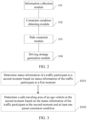
- FIG. 3 is a schematic flowchart of a path constraint method according to an embodiment of this application.
- this application provides operation steps of the method shown in the following embodiments or accompanying drawings, the method may include more or fewer operation steps based on conventional or non-creative efforts. For steps that have no necessary causal relationship logically, a performing sequence of the steps is not limited to a performing sequence provided in embodiments of this application.
- the method may be performed in a sequence or in parallel (for example, in a parallel processor or a multi-thread processing environment) according to the method shown in the embodiments or accompanying drawings. As shown in FIG. 3 , the method includes the following steps.
- Step S301 Determine status information of a traffic participant at a second moment based on status information of the traffic participant at a first moment.
- an ego vehicle cannot obtain the status information of the traffic participant (including the ego vehicle and another traffic participant) at the second moment by using an information collection apparatus (for example, a sensor such as a camera, a lidar, a millimeter wave radar, or an ultrasonic radar, a high-definition map, or a positioning module such as BeiDou or a GPS) provided on the ego vehicle.
- an information collection apparatus for example, a sensor such as a camera, a lidar, a millimeter wave radar, or an ultrasonic radar, a high-definition map, or a positioning module such as BeiDou or a GPS
- the ego vehicle may predict the status information of the traffic participant at the second moment based on the status information of the traffic participant at the first moment.
- the status information of the ego vehicle and the another traffic participant at the second moment includes but is not limited to a speed, a location, a traveling direction, a possible steering measure, and the like.
- the first moment may be any moment before the second moment.
- a time interval between the first moment and the second moment may be determined according to a requirement, for example, may be 10 minutes, half an hour, one hour, or the like. It may be understood that a smaller time interval between the first moment and the second moment indicates a smaller error between the status information of the traffic participant at the second moment determined based on the status information of the traffic participant at the first moment and actual status information of the traffic participant at the second moment. In other words, a smaller time interval between the first moment and the second moment indicates higher accuracy of the status information of the traffic participant at the second moment determined in step S301.
- a larger time interval between the first moment and the second moment indicates a larger error between the status information of the traffic participant at the second moment determined based on the status information of the traffic participant at the first moment and actual status information of the traffic participant at the second moment.
- a larger time interval between the first moment and the second moment indicates lower accuracy of the status information of the traffic participant at the second moment determined in step S301.
- the ego vehicle may obtain, at the first moment, the status information of the traffic participant at the first moment by using an information collection module provided on the ego vehicle, for example, a sensor (for example, a camera, a lidar, a millimeter wave radar, or an ultrasonic radar), a high-definition map, and a positioning module.
- an information collection module provided on the ego vehicle, for example, a sensor (for example, a camera, a lidar, a millimeter wave radar, or an ultrasonic radar), a high-definition map, and a positioning module.
- the status information of the traffic participant at the first moment may be actual status information collected by using the information collection module.
- the ego vehicle may determine the status information of the traffic participant at the first moment based on status information of the traffic participant at a third moment.
- the third moment is before the first moment.
- the ego vehicle may obtain, at the third moment by using the information collection module provided on the ego vehicle, the status information of the traffic participant at the third moment.
- the status information of the traffic participant at the first moment may be status information estimated based on the status information of the traffic participant at the third moment.
- the traffic participant includes but is not limited to another vehicle, a pedestrian, a non-motor vehicle, a traffic light, traffic police, and indication information such as a sign.
- the status information of the traffic participant includes but is not limited to a speed, a location, a traveling direction, and the like of the traffic participant. The traffic participant and the status information of the traffic participant are not described herein again.
- Step S302 Determine a safe traveling area of the ego vehicle at the second moment based on the status information of the traffic participant at the second moment and at least one preset constraint condition.
- the preset constraint condition may be used to limit the location of the ego vehicle. For example, a location of the ego vehicle at the second moment may be limited based on the status information of the traffic participant at the second moment and the at least one preset constraint condition, to obtain the safe traveling area in which the ego vehicle can safely travel at the second moment.
- the at least one preset constraint condition includes one or more of the following: a safety model, a traffic rule, a customized rule, driving habit information, and vehicle performance information.
- the preset constraint condition includes a safety model.
- the safety model may be a model established based on information such as a speed and a safe distance, and the safety model may be a model established based on a right of way.
- the safety model may include a responsibility-sensitive safety (Responsibility-Sensitive Safety, RSS) model and a safety force field (Safety Force Field, SFF) model.
- RSS responsibility-sensitive safety
- SFF Safety Force Field
- the RSS model defines the following rules: Don't hit the car in front of you; Don't cut in recklessly; Right of way is given, not taken; Be cautious in areas with limited visibility; If you can avoid a crash without causing another one, you must.
- safe distances may be classified into the following types: The safe distance is determined based on a control coordinate system, for example, is specified as 10 meters. The safe distance is determined based on a time interval. For example, a safe time interval is specified as three seconds, indicating that no collision occurs within three seconds at a current traveling speed and direction.
- the foregoing safety models are merely examples, and are not intended to limit the safety model. Another safety model may be further used in embodiments of this application.
- FIG. 4 is a schematic diagram of an example of a safe traveling area.
- a safe traveling area of a vehicle 1 is a circular area whose center is the vehicle 1 and whose radius is a safe distance.
- safety of the vehicle 1 can be ensured only when the circular area does not include another traffic participant.
- the vehicle 1 determines a location of a vehicle 2 at a second moment based on a location, a speed, and a traveling direction of the vehicle 2 at the first moment. As shown in FIG.
- a location of the vehicle 1 at the second moment cannot be beyond a center of a dashed-line circular area (a radius of the dashed-line circular area is the safe distance).
- the vehicle 1 may alternatively not move within a time period from the first moment to the second moment, and in this case, a safe traveling area of the vehicle 1 at the second moment is an elliptical area shown in FIG. 4 .
- the preset constraint condition may include a traffic rule.
- the traffic rule includes but is not limited to a speed limit (for example, a speed limit of 80 km/h, or a speed limit of 60 km/h), slowing down at a road junction, stopping at a red light, slowing down when a yellow light blinks, U-turn prohibited, lane change prohibited, or vehicle reversing prohibited.
- speed limit for example, a speed limit of 80 km/h, or a speed limit of 60 km/h
- slowing down at a road junction stopping at a red light
- slowing down when a yellow light blinks U-turn prohibited, lane change prohibited, or vehicle reversing prohibited.
- FIG. 5 is a schematic diagram of an example of a safe traveling area.
- a safe traveling area of a vehicle 1 is a circular area whose center is the vehicle 1 and whose radius is a safe distance.
- safety of the vehicle 1 can be ensured only when the circular area does not include another traffic participant.
- a traffic rule is as follows: A speed limit is 60 km/h and vehicle reversing is prohibited.
- the vehicle 1 cannot travel too fast within a time interval from the first moment to a second moment, an area behind a rear side of the vehicle 1 is a traveling-prohibited area, and a safe traveling area of the vehicle 1 at the second moment is a thin-line elliptical area shown in FIG. 5 .
- the traffic rule is as follows: stopping at a red light, slowing down when a yellow light blinks, and prohibiting vehicle reversing. It is assumed that a yellow light of a traffic light blinks at the first moment. Based on this, the vehicle 1 determines that the traffic light turns red at the second moment.
- the safe traveling area of the vehicle 1 at the second moment may be a thick-line elliptical area shown in FIG. 5 . It can be learned that a range of the thick-line elliptical area is smaller than a range of the thin-line elliptical area.
- the preset constraint condition may further include a customized rule, driving habit information, vehicle performance information, and the like.
- the customized rule may include a customized speed upper limit, a customized acceleration upper limit, a customized yaw angular velocity upper limit, or the like.
- the driving habit information is prudent driving or dislike of abrupt braking.
- a large vehicle-following distance is set.
- the vehicle performance information may include low braking sensitivity, a large acceleration, and the like. In this case, a large vehicle-following distance may be set.
- the preset constraint condition may further include another condition that can limit a location of a vehicle to ensure safety of the vehicle.
- the preset constraint condition is not limited in embodiments of this application.
- step S302 may include: for any preset constraint condition of the at least one preset constraint condition, determining a safe range corresponding to the preset constraint condition based on the status information of the traffic participant at the second moment and the preset constraint condition; and determining an intersection of safe ranges corresponding to all preset constraint conditions in the at least one constraint condition as the safe traveling area of the ego vehicle at the second moment.
- each preset constraint condition corresponds to one safe range and each safe range is a traveling area that the ego vehicle should strictly use
- the safe ranges may be combined to obtain the safe traveling area of the ego vehicle at the second moment. If a location is in the safe ranges corresponding to all preset constraint conditions, it indicates that the location is safe. If a location is in a safe range corresponding to one preset constraint condition or in safe ranges corresponding to some preset constraint conditions, but is outside a safe range corresponding to another preset constraint condition, it indicates that the location is risky and is not completely safe. If a location is not in a safe range corresponding to any preset constraint condition, it indicates that the location is dangerous. Therefore, in this embodiment of this application, the intersection of the safe ranges corresponding to all preset constraint conditions at the second moment may be determined as the safe traveling area of the ego vehicle at the second moment, to ensure safety of the vehicle.
- a preset constraint condition may be added, deleted, or updated according to a requirement.
- safe ranges may be determined based on some or all preset constraint conditions selected according to a requirement.
- the ego vehicle has determined the safe traveling area at the second moment.
- the status information of the traffic participant at the second moment may be determined based on the status information of the traffic participant at the first moment
- the safe traveling area of the ego vehicle at the second moment may be determined based on the status information of the traffic participant at the second moment and the at least one preset constraint condition.
- the preset constraint condition is used to constrain the safe traveling area of the vehicle at the second moment, and guidance is provided, before path planning, for an area in which a path is located. This reduces ineffective track calculation, and reduces a calculation amount and implements efficient and safe constraint on a path of the vehicle on the basis of ensuring safety.
- a corresponding safe traveling area of the vehicle also changes with time.
- To plan a path of the vehicle there is a need to obtain safe traveling areas at a plurality of moments.
- the method may further include obtaining a plurality of safe traveling areas at a plurality of moments; and performing path planning based on the plurality of safe traveling areas at the plurality of moments, so that the ego vehicle remains in the safe traveling areas when traveling in a planned path.
- Each moment corresponds to one safe traveling area
- the plurality of moments include the second moment
- the plurality of safe traveling areas include the safe traveling area at the second moment.
- a planned path of the vehicle is in the safe traveling areas, so that the ego vehicle is safe when traveling in the planned path, and safety is improved.
- guiding path planning based on the safe traveling area instead of determining a path planning result, can reduce a possibility of repeatedly performing path planning or even failing to perform effective path planning, so that a calculation amount is reduced, and efficiency is improved.
- the plurality of moments may form a time sequence, and the time sequence is arranged in a chronological order of the moments (or from earlier to later).
- a time interval between any two adjacent moments in the time sequence may be set according to a requirement.
- time intervals between any two adjacent moments in the time sequence may be the same or different.
- the time sequence may include a moment T1, a moment T2, a moment T3, and a moment T4.
- the moment T1, the moment T2, the moment T3, and the moment T4 are arranged in a chronological order, to be specific, the moment T1 is before the moment T2, the moment T2 is before the moment T3, and the moment T3 is before the moment T4.
- the ego vehicle may perform path planning based on a safe traveling area at the moment T1, a safe traveling area at the moment T2, a safe traveling area at the moment T3, and a safe traveling area at the moment T4, so that the ego vehicle remains in the safe traveling areas when traveling in a planned path.
- the method further includes storing the plurality of moments and the safe traveling areas at the moments. This facilitates subsequent path planning and driving strategy making, and also facilitates visual display to improve user friendliness.
- display may be implemented in a center console.
- the ego vehicle may store the plurality of moments and the safe traveling areas at the moments in a manner of imaging, a matrix, serialization, or the like.
- FIG. 6 is a schematic diagram of superimposition of a plurality of safe traveling areas according to an embodiment of this application. As shown in FIG. 6 , when the safe traveling area at the moment T1, the safe traveling area at the moment T2, the safe traveling area at the moment T3, and the safe traveling area at the moment T4 are superimposed, a three-dimensional representation form like contour lines is obtained. In still another example, an area in which the ego vehicle is located at each moment is represented by using a matrix.
- a safe traveling area may be represented as a mask (mask) in the matrix, and each matrix and a corresponding mask represent a safe traveling area at one moment.
- FIG. 7 is a schematic diagram of superimposition of a plurality of safe traveling areas according to an embodiment of this application. As shown in FIG. 7 , an elliptical area in an area in which the ego vehicle is located at the moment T1 is the safe traveling area of the ego vehicle at the moment T1. It may be understood that an elliptical area (not shown) in an area (as shown in FIG.
- a termination condition of calculation on safe traveling areas may be determined based on a hardware configuration or a manually preset threshold.
- the vehicle may determine a quantity of the obtained safe traveling areas based on a hardware configuration of the ego vehicle or a preset threshold.
- a processing capability of a processor When a processing capability of a processor is weak, a small quantity of safe traveling areas may be set. When the processing capability of the processor is strong, a large quantity of safe traveling areas may be set. For example, when the processing capability of the processor is weak, the safe traveling area at the moment T1, the safe traveling area at the moment T2, and the safe traveling area at the moment T3 may be calculated. When the processing capability of the processor is strong, the safe traveling area at the moment T1, the safe traveling area at the moment T2, ..., and a safe traveling area at a moment T10 may be calculated.
- the safe traveling areas at the moments may be updated as status information of the traffic participant at the moments is updated. In this way, reliability and accuracy of the safe traveling area can be improved, so that safety of the vehicle is improved.
- FIG. 8 is a schematic diagram of an example of a safe traveling area according to an embodiment of this application.
- a moment T1 is before a moment T2, and the moment T2 is before a moment T3.
- a safe traveling area of a vehicle 1 at the moment T1 is an elliptical area of a black thin line shown in FIG. 8 .
- a vehicle 2 travels in a lane on a left side of the vehicle 1 and is in front of the vehicle 1, and there is a non-motor vehicle in front of the vehicle 2.
- the vehicle 1 determines status information of a traffic participant at the moment T2 based on status information (including a location, a traveling direction, and a speed) of the traffic participant (including the vehicle 1, the vehicle 2, and the non-motor vehicle) at the moment T1. Because there is a non-motor vehicle lane in front of the vehicle 2, the vehicle 1 predicts that the vehicle 2 may slow down or turn right to change the lane at the moment T2. As shown in FIG. 8 , according to constraint by a safe distance, a location of the vehicle 1 at the moment T2 cannot be beyond a center of a dashed-line circular area (a radius of the dashed-line circular area is the safe distance) at the moment T2.
- the vehicle 1 cannot reverse, and in this case, the location of the vehicle 1 at the moment T2 cannot be behind a location of the vehicle 1 at the moment T1. Therefore, the vehicle 1 determines, based on the status information (that is, predicted status information of the vehicle 2 at the moment T2) of the traffic participant at the moment T2 and at least one preset constraint condition (including the safe distance and the traffic rule), that a safe traveling area of the vehicle 1 at the moment T2 is an elliptical area of a gray thick line shown in FIG. 8 .
- the status information that is, predicted status information of the vehicle 2 at the moment T2
- at least one preset constraint condition including the safe distance and the traffic rule
- the vehicle 1 determines status information of the traffic participant at the moment T3 based on the status information (including a location, a traveling direction, and a speed) of the traffic participant (including the vehicle 1, the vehicle 2, and the non-motor vehicle) at the moment T2. Because the vehicle 2 may slow down or turn right to change the lane at the moment T2, at the moment T3, the vehicle 2 may continue to slow down or have changed the lane to a lane in which the vehicle 1 is located. As shown in FIG. 8 , according to constraint by a safe distance, the vehicle cannot be beyond, at the moment T3, a center of a dashed-line circular area (a radius of the dashed-line circular area is the safe distance) at the moment T3.
- the vehicle 1 cannot reverse, and in this case, a location of the vehicle 1 at the moment T3 cannot be behind the location of the vehicle 1 at the moment T2. Therefore, the vehicle 1 determines, based on the status information (that is, predicted status information of the vehicle 2 at the moment T3) of the traffic participant at the moment T3 and at least one constraint condition (including the safe distance and the traffic rule), that a safe traveling area of the vehicle 1 at the moment T3 is an elliptical area of a black thick line shown in FIG. 8 .
- the status information that is, predicted status information of the vehicle 2 at the moment T3
- at least one constraint condition including the safe distance and the traffic rule
- a distance for which the safe traveling area of the vehicle 1 at the moment T3 moves relative to the safe traveling area of the vehicle 1 at the moment T2 in a forward direction of the vehicle 1 is smaller than a distance for which the safe traveling area of the vehicle 1 at the moment T2 moves relative to the safe traveling area of the vehicle 1 at the moment T1 in the forward direction of the vehicle 1, so that the vehicle 1 can slow down to avoid rear-ending the vehicle 2.
- FIG. 9 is a schematic diagram of an example of a safe traveling area sequence according to an embodiment of this application.
- a moment T1 is before a moment T2, and the moment T2 is before a moment T3.
- a safe traveling area of a vehicle 1 at the moment T1 is an elliptical area of a black thin line shown in FIG. 9 .
- a vehicle 2 and the vehicle 1 are in a same lane, the vehicle 2 travels in front of the vehicle 1, and there is a traffic light in front of the vehicle 1 and the vehicle 2.
- the vehicle 1 determines status information of a traffic participant at the moment T2 based on status information (including a location, a traveling direction, and a color of the traffic light) of the traffic participant (including the vehicle 1, the vehicle 2, and the traffic light) at the moment T1. Because the traffic light is green at the moment T1, the vehicle 1 predicts that the traffic light turns yellow at the moment T2, and the vehicle 2 may slow down. As shown in FIG. 9 , according to constraint by a safe distance, a location of the vehicle 1 at the moment T2 cannot be beyond a center of a dashed-line circular area (a radius of the dashed-line circular area is the safe distance) at the moment T2.
- the vehicle 1 determines status information of the traffic participant at the moment T3 based on the status information (including a location, a traveling direction, and a color of the traffic light) of the traffic participant (including the vehicle 1, the vehicle 2, and the traffic light) at the moment T2. Because the traffic light turns yellow at the moment T2, the vehicle 1 predicts that the traffic light turns red at the moment T3, and the vehicle 2 stops at a stop line. As shown in FIG. 9 , according to constraint by a safe distance, the vehicle cannot be beyond, at the moment T3, a center of a dashed-line circular area (a radius of the dashed-line circular area is the safe distance) at the moment T3.
- the vehicle 1 cannot reverse, and in this case, a location of the vehicle 1 at the moment T3 cannot be behind the location of the vehicle 1 at the moment T2. Therefore, the vehicle 1 determines, based on the status information (that is, predicted status information of the vehicle 2 at the moment T3 and status information of the traffic light at the moment T3) of the traffic participant at the moment T3 and at least one constraint condition (including the safe distance and the traffic rule), that a safe traveling area of the vehicle 1 at the moment T3 is an elliptical area of a black thick line shown in FIG. 9 .
- the status information that is, predicted status information of the vehicle 2 at the moment T3 and status information of the traffic light at the moment T3
- at least one constraint condition including the safe distance and the traffic rule
- a distance for which the safe traveling area of the vehicle 1 at the moment 3 moves relative to the safe traveling area of the vehicle 1 at the moment T2 in a forward direction of the vehicle 1 is smaller than a distance for which the safe traveling area of the vehicle 1 at the moment T2 moves relative to the safe traveling area of the vehicle 1 at the moment T1 in the forward direction of the vehicle 1, so that the vehicle 1 can slow down to avoid rear-ending the vehicle 2.
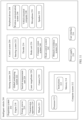
- FIG. 10 is a schematic diagram of a structure of a path constraint apparatus according to an embodiment of this application. As shown in FIG. 10 , the apparatus 400 may include:
- the at least one preset constraint condition includes one or more of the following: a safety model, a traffic rule, a customized rule, driving habit information, and vehicle performance information.
- the area determining module is further configured to:
- the apparatus further includes:
- the apparatus further includes: a storage module, configured to store the plurality of moments and the safe traveling areas at the moments.
- the apparatus further includes: a quantity determining module, configured to determine a quantity of the obtained safe traveling areas based on a hardware configuration of the ego vehicle or a preset threshold.
- the status information of the traffic participant at the second moment may be determined based on the status information of the traffic participant at the first moment
- the safe traveling area of the ego vehicle at the second moment may be determined based on the status information of the traffic participant at the second moment and the at least one preset constraint condition.
- the preset constraint condition is used to constrain the safe traveling area of the vehicle at the second moment, and guidance is provided, before path planning, for an area in which a path is located. This reduces ineffective track calculation, and reduces a calculation amount and implements efficient and safe constraint on a path of the vehicle on the basis of ensuring safety.
- FIG. 11 is a functional block diagram of an intelligent vehicle 200 according to an embodiment of this application.
- a fully or partially autonomous driving mode may be configured for the intelligent vehicle 200.
- the intelligent vehicle 200 may control the intelligent vehicle 200 when being in the autonomous driving mode, determine, through manual operations, current statuses of the vehicle and a surrounding environment of the vehicle, possible behavior of at least one another vehicle in the surrounding environment, and a confidence level corresponding to a possibility of performing the possible behavior by the another vehicle, and control the intelligent vehicle 200 based on determined information.
- the intelligent vehicle 200 may be set to operate without interacting with a person.
- the intelligent vehicle 200 may include various subsystems, for example, a propulsion system 202, a sensor system 204, a control system 206, one or more peripheral devices 208, a power supply 210, a computer system 212, and a user interface 216.
- the intelligent vehicle 200 may include more or fewer subsystems, and each subsystem may include a plurality of elements.
- all the subsystems and elements of the intelligent vehicle 200 may be interconnected in a wired or wireless manner.
- the propulsion system 202 may include a component that provides power for the intelligent vehicle 200 to move.
- the propulsion system 202 may include an engine 218, an energy source 219, a transmission apparatus 220, and wheels/tires 221.
- the engine 218 may be an internal combustion engine, a motor, an air compression engine, or a combination of other types of engines, for example, a hybrid engine including a gasoline engine and a motor or a hybrid engine including an internal combustion engine and an air compression engine.
- the engine 218 converts the energy source 219 into mechanical energy.
- Examples of the energy source 219 include gasoline, diesel, other oil-based fuels, propane, other compressed gas-based fuels, ethanol, a solar panel, a battery, and another power source.
- the energy source 219 may also provide energy for another system of the intelligent vehicle 200.
- the transmission apparatus 220 may transmit mechanical power from the engine 218 to the wheels 221.
- the transmission apparatus 220 may include a gearbox, a differential, and a drive shaft.
- the transmission apparatus 220 may further include another component, for example, a clutch.
- the drive shaft may include one or more shafts that may be coupled to one or more of the wheels 221.
- the sensor system 204 may include several sensors for sensing information about a surrounding environment of the intelligent vehicle 200.
- the sensor system 204 may include a global positioning system 222 (the positioning system may be a GPS, a BeiDou system, or another positioning system), an inertial measurement unit (inertial measurement unit, IMU) 224, a radar 226, a laser rangefinder 228, and a camera 230.
- the sensor system 204 may further include sensors (for example, an in-vehicle air quality monitor, a fuel gauge, and an engine oil temperature gauge) in an internal system of the monitored intelligent vehicle 200. Sensor data from one or more of these sensors may be used to detect an object and corresponding features (a location, a shape, a direction, a speed, and the like) of the object. Such detection and identification are key functions for a safe operation of the autonomous intelligent vehicle 200.
- the positioning system 222 may be configured to estimate a geographical location of the intelligent vehicle 200.
- the IMU 224 is configured to sense location and orientation changes of the intelligent vehicle 200 based on an inertial acceleration.
- the IMU 224 may be a combination of an accelerometer and a gyroscope.
- the IMU 224 may be configured to measure curvature of the intelligent vehicle 200.
- the radar 226 may sense an object in the surrounding environment of the intelligent vehicle 200 by using a radio signal. In some embodiments, in addition to sensing an object, the radar 226 may be further configured to sense a speed and/or a moving direction of the object.
- the laser rangefinder 228 may sense, by using laser, an object in an environment in which the intelligent vehicle 200 is located.
- the laser rangefinder 228 may include one or more laser sources, a laser scanner, one or more detectors, and another system component.
- the camera 230 may be configured to capture a plurality of images of the surrounding environment of the intelligent vehicle 200.
- the camera 230 may be a static camera or a video camera.
- the control system 206 controls operations of the intelligent vehicle 200 and components of the intelligent vehicle 200.
- the control system 206 may include various elements, including a steering system 232, a throttle 234, a brake unit 236, a sensor fusion algorithm 238, a computer vision system 240, a route control system 242, and an obstacle avoidance system 244.
- the steering system 232 may operate to adjust a traveling direction of the intelligent vehicle 200.
- the steering system 232 may be a steering wheel system.
- the throttle 234 is configured to control an operating speed of the engine 218, so as to control a speed of the intelligent vehicle 200.
- the brake unit 236 is configured to control the intelligent vehicle 200 to decelerate.
- the brake unit 236 may use friction to slow the wheels 221.
- the brake unit 236 may convert kinetic energy of the wheels 221 into a current.
- the brake unit 236 may alternatively slow a rotating speed of the wheels 221 in another manner, so as to control the speed of the intelligent vehicle 200.
- the computer vision system 240 may operate to process and analyze an image captured by the camera 230, to identify an object and/or a feature in the surrounding environment of the intelligent vehicle 200.
- the object and/or the feature may include a traffic signal, a road boundary, and an obstacle.
- the computer vision system 240 may use an object identification algorithm, a structure from motion (Structure from Motion, SFM) algorithm, video tracking, and another computer vision technology.
- the computer vision system 240 may be configured to: draw a map for an environment, track an object, estimate a speed of the object, and the like.
- the route control system 242 is configured to determine a traveling route of the intelligent vehicle 200. In some embodiments, the route control system 242 may determine a traveling route for the intelligent vehicle 200 with reference to data from a sensor 238, the GPS 222, and one or more predetermined maps.
- the obstacle avoidance system 244 is configured to identify, evaluate, and avoid or otherwise bypass a potential obstacle in the environment of the intelligent vehicle 200.
- control system 206 may additionally or alternatively include a component other than those shown and described. Alternatively, the control system 206 may delete some of the components shown above.
- the intelligent vehicle 200 interacts with an external sensor, another vehicle, another computer system, or a user by using the peripheral device 208.
- the peripheral device 208 may include a wireless communication system 246, a vehicle-mounted computer 248, a microphone 250, and/or a speaker 252.
- the peripheral device 208 provides a means for a user of the intelligent vehicle 200 to interact with the user interface 216.
- the vehicle-mounted computer 248 may provide information for the user of the intelligent vehicle 200.
- the user interface 216 may further operate the vehicle-mounted computer 248 to receive an input of the user.
- the vehicle-mounted computer 248 may perform an operation by using a touchscreen.
- the peripheral device 208 may provide a means for the intelligent vehicle 200 to communicate with another device located in the vehicle.
- the microphone 250 may receive audio (for example, a voice command or another audio input) from the user of the intelligent vehicle 200.
- the speaker 252 may output audio to the user of the intelligent vehicle 200.
- the wireless communication system 246 may wirelessly communicate with one or more devices directly or through a communication network.
- the wireless communication system 246 may use 3G cellular communication such as CDMA, EVD0, or GSM/GPRS, 4G cellular communication such as LTE, or 5G cellular communication.
- the wireless communication system 246 may communicate with a wireless local area network (wireless local area network, WLAN) through Wi-Fi.
- the wireless communication system 246 may directly communicate with a device through an infrared link, Bluetooth, or ZigBee.
- Other wireless protocols for example, various vehicle communication systems such as the wireless communication system 246, may include one or more dedicated short range communications (dedicated short range communications, DSRC) devices, and these devices may include public and/or private data communication between vehicles and/or roadside stations.
- DSRC dedicated short range communications
- the power supply 210 may supply power to various components of the intelligent vehicle 200.
- the power supply 210 may be a rechargeable lithium-ion or lead-acid battery.
- One or more battery packs of such a battery may be configured as a power supply to supply power to various components of the intelligent vehicle 200.
- the power supply 210 and the energy source 219 may be implemented together as those implemented together in some all-electric vehicles.
- the computer system 212 may include at least one processor 213.
- the processor 213 executes instructions 215 stored in a non-transitory computer-readable medium such as a data storage apparatus 214.
- the computer system 212 may alternatively be a plurality of computing devices that control an individual component or a subsystem of the intelligent vehicle 200 in a distributed manner.
- the processor 213 may be any conventional processor, for example, a commercially available CPU. Alternatively, the processor may be a dedicated device such as an ASIC or another hardware-based processor.
- FIG. 11 functionally shows the processor, the memory, and another element of a computer 120 in a same block, a person of ordinary skill in the art should understand that the processor, the computer, or the memory may actually include a plurality of processors, computers, or memories that may or may not be stored in a same physical housing.
- the memory may be a hard disk drive, or another storage medium located in a housing different from that of the computer 120. Therefore, a reference to the processor or the computer is understood as including a reference to a set of processors or computers or memories that may or may not operate in parallel.
- some components such as a steering component and a deceleration component may include their respective processors.
- the processor performs only computation related to a component-specific function.
- the processor may be located far away from the vehicle and wirelessly communicate with the vehicle.
- some of the processes described herein are performed by a processor disposed inside the vehicle, while others are performed by a remote processor, including performing a step necessary for single manipulation.
- the data storage apparatus 214 may include the instructions 215 (for example, program logic), and the instructions 215 may be executed by the processor 213 to perform various functions, including those functions described above, of the intelligent vehicle 200.
- the data storage apparatus 224 may further include additional instructions, including an instruction for sending data to, receiving data from, interacting with, and/or controlling one or more of the propulsion system 202, the sensor system 204, the control system 206, and the peripheral device 208.
- the memory 214 may further store data, such as a road map, route information, and a location, a direction, a speed, and other such vehicle data of the vehicle, and other information. Such information may be used by the intelligent vehicle 200 and the computer system 212 during operation of the intelligent vehicle 200 in an autonomous mode, a semi-autonomous mode, and/or a manual mode.
- the user interface 216 is configured to provide information for or receive information from the user of the intelligent vehicle 200.
- the user interface 216 may include one or more input/output devices in a set of peripheral devices 208, for example, the wireless communication system 246, the vehicle-mounted computer 248, the microphone 250, and the speaker 252.
- the computer system 212 may control a function of the intelligent vehicle 200 based on inputs received from various subsystems (for example, the wireless communication system 246, the propulsion system 202, the sensor system 204, and the control system 206) and from the user interface 216. For example, the computer system 212 may plan, by using an input from the wireless communication system 246, a lane line at a road junction that needs to be passed through during autonomous driving, and an obstacle at the road junction may be avoided based on the lane line. In some embodiments, the computer system 212 may operate to provide control over many aspects of the intelligent vehicle 200 and the subsystems of the intelligent vehicle 200.
- various subsystems for example, the wireless communication system 246, the propulsion system 202, the sensor system 204, and the control system 206
- the computer system 212 may plan, by using an input from the wireless communication system 246, a lane line at a road junction that needs to be passed through during autonomous driving, and an obstacle at the road junction may be avoided based on the lane line.
- the computer system 212 may further receive information from another computer system, or transfer information to another computer system.
- the computer system 212 may transfer sensor data collected from the sensor system 204 of the intelligent vehicle 200 to another remote computer system, and submit the data to the another computer system for processing.
- data collected by various sensors in the sensor system 204 is fused by the another computer system. Then, data or an analysis result obtained after the fusion is returned to the computer system 212.
- data from the computer system 212 may be transmitted to a computer system on a cloud side through a network for further processing.
- the network and an intermediate node may include various configurations and protocols, including Internet, World Wide Web, an intranet, a virtual private network, a wide area network, a local area network, a private network using proprietary communication protocols of one or more companies, Ethernet, Wi-Fi, HTTP, and various combinations thereof.
- Such communication may be performed by any device such as a modem and a wireless interface that can transmit data to and from another computer.
- the remote computer system interacting with the computer system 212 in the intelligent vehicle 200 may include a server having a plurality of computers, such as a load balancing server cluster, and exchanges information with different nodes of the network for the objective of receiving, processing, and transmitting data from the computer system 212.
- the server may include a processor, a memory, instructions, data, and the like.
- the data of the server may include weather-related information.
- the server may receive, monitor, store, update, and transmit various pieces of weather-related information.
- the information may include, for example, rainfall, cloud, and/or temperature information in a form of report, radar information, forecast, or the like.
- the data of the server may further include high-definition map data and traffic information of a road section in front (for example, real-time traffic congestion, and occurrence of a traffic accident).
- the server may send the high-definition map data, traffic information, and the like to the computer system 212, so as to assist the intelligent vehicle 200 in performing better autonomous driving and ensure driving safety.
- one or more of the foregoing components may be installed separately from or associated with the intelligent vehicle 200.
- the data storage apparatus 214 may be partially or completely separated from the intelligent vehicle 200.
- the foregoing components may be communicatively coupled together in a wired and/or wireless manner.
- the foregoing components are merely examples. During actual application, the components in the foregoing modules may be added or deleted according to an actual requirement. FIG. 11 shall not be understood as a limitation on embodiments of this application.
- An autonomous driving vehicle that travels on a road may identify an object in a surrounding environment of the vehicle, to determine to adjust a current speed.
- the object may be another vehicle, a traffic control device, or another type of object.
- each identified object may be considered independently, and may be used to determine a speed to be adjusted to by the autonomous driving vehicle based on features of each object, such as a current speed of the object, an acceleration of the object, and a distance between the object and the vehicle.
- the autonomous driving intelligent vehicle 200 or a computing device associated with the autonomous driving intelligent vehicle 200 may predict behavior of the identified object based on a feature of the identified object and a status of the surrounding environment (for example, traffic, rain, and ice on a road).
- a feature of the identified object for example, traffic, rain, and ice on a road.
- all identified objects depend on behavior of each other, and therefore all the identified objects may be considered together to predict behavior of a single identified object.
- the intelligent vehicle 200 can adjust the speed of the intelligent vehicle 200 based on the predicted behavior of the identified object.
- the autonomous driving vehicle can determine, based on the predicted behavior of the object, a specific stable state to which the vehicle needs to be adjusted (for example, acceleration, deceleration, or stop).
- a specific stable state to which the vehicle needs to be adjusted for example, acceleration, deceleration, or stop.
- another factor for example, a transverse location of the intelligent vehicle 200 on a traveling road, curvature of the road, or proximity between static and dynamic objects, may be considered to determine the speed of the intelligent vehicle 200.
- the computing device may further provide an instruction for modifying a steering angle of the intelligent vehicle 200, so that the autonomous driving vehicle follows a given track and/or maintains safe lateral and longitudinal distances from an object (for example, a car in an adjacent lane on the road) near the autonomous driving vehicle.
- an object for example, a car in an adjacent lane on the road
- the intelligent vehicle 200 may be a car, a truck, a motorcycle, a bus, a boat, an airplane, a helicopter, a lawn mower, a recreational vehicle, a playground vehicle, a construction device, a trolley, a golf cart, a train, a handcart, or the like. This is not specifically limited in embodiments of this application.
- the functional diagram of the intelligent vehicle 200 in FIG. 11 is merely an example implementation in embodiments of this application.
- the intelligent vehicle 200 in embodiments of this application includes but is not limited to the foregoing structure.
- FIG. 12 is a schematic diagram of a structure of a path constraint apparatus according to an embodiment of this application.
- the apparatus may include at least one processor 501, a memory 502, an input/output device 503, and a bus 504. The following describes each component of the path constraint apparatus in detail with reference to FIG. 12 .
- the processor 501 is a control center of the path constraint apparatus, and may be one processor, or may be a collective term of a plurality of processing elements.
- the processor 501 is a CPU, an application-specific integrated circuit (Application-Specific Integrated Circuit, ASIC), or one or more integrated circuits that are configured to implement embodiments of the present disclosure, for example, one or more microprocessors (Digital Signal Processors, DSPs), or one or more field programmable gate arrays (Field Programmable Gate Arrays, FPGAs).
- the processor 501 may perform various functions of the path constraint apparatus by running or executing a software program stored in the memory 502 and invoking data stored in the memory 502.
- the processor 501 may include one or more CPUs, for example, a CPU 0 and a CPU 1 shown in the figure.
- the path constraint apparatus may include a plurality of processors, for example, the processor 501 and a processor 505 shown in FIG. 12 .
- Each of the processors may be a single-core processor (single-CPU) or a multi-core processor (multi-CPU).
- the processor herein may be one or more devices, circuits, and/or processing cores configured to process data (for example, computer program instructions).
- the memory 502 may be a read-only memory (Read-Only memory, ROM) or another type of static storage device that can store static information and instructions, a random access memory (Random Access Memory, RAM) or another type of dynamic storage device that can store information and instructions, an electrically erasable programmable read-only memory (Electrically Erasable Programmable Read-Only Memory, EEPROM), a compact disc read-only memory (Compact Disc Read-Only Memory, CD-ROM) or another compact disc storage, an optical disc storage (including a compact disc, a laser disc, an optical disc, a digital versatile disc, a Blue-ray disc, or the like), a magnetic disk storage medium or another magnetic storage device, or any other medium that can be configured to carry or store expected program code in a form of instruction or data structure and that can be accessed by a computer.
- the memory 502 may exist independently, and is connected to the processor 501 through the bus 504. Alternatively, the memory 502 and the processor 501
- the input/output device 503 is configured to communicate with another device or a communication network, for example, Ethernet, a radio access network (Radio access network, RAN), or a wireless local area network (Wireless Local Area Network, WLAN).
- the input/output device 503 may include all or a part of a baseband processor, and may alternatively include a radio frequency (Radio Frequency, RF) processor.
- the RF processor is configured to send or receive an RF signal.
- the baseband processor is configured to process a baseband signal converted from an RF signal, or a baseband signal to be converted into an RF signal.
- the input/output device 503 may include a transmitter and a receiver.
- the transmitter is configured to send a signal to another device or a communication network
- the receiver is configured to receive a signal sent by another device or a communication network.
- the transmitter and the receiver may exist independently, or may be integrated together.
- the bus 504 may be an industry standard architecture (Industry Standard Architecture, ISA) bus, a peripheral component interconnect (Peripheral Component Interconnect, PCI) bus, an extended industry standard architecture (Extended Industry Standard Architecture, EISA) bus, or the like.
- ISA Industry Standard Architecture
- PCI peripheral component interconnect
- EISA Extended Industry Standard Architecture
- the bus may be classified into an address bus, a data bus, a control bus, and the like. For ease of representation, only one thick line is used to represent the bus in FIG. 12 , but this does not mean that there is only one bus or only one type of bus.
- the structure of the device shown in FIG. 12 constitutes no limitation on the path constraint apparatus.
- the apparatus may include more or fewer components than those shown in the figure, or combine some components, or have different component arrangements.
- An embodiment of this application provides a path constraint apparatus, including a processor and a memory configured to store instructions capable of being executed by the processor.
- the processor is configured to implement the foregoing method when executing the instructions.
- An embodiment of this application provides a computer-readable storage medium, storing computer program instructions. When the computer program instructions are executed by a processor, the foregoing method is implemented.
- An embodiment of this application provides a computer program product, including computer-readable code or a nonvolatile computer-readable storage medium carrying computer-readable code.
- the computer-readable code When the computer-readable code is run in a processor in an electronic device, the processor in the electronic device performs the foregoing method.
- the computer-readable storage medium may be a tangible device that can retain and store instructions for use by an instruction execution device.
- the computer-readable storage medium may be (but is not limited to), for example, an electronic storage device, a magnetic storage device, an optical storage device, an electromagnetic storage device, a semiconductor storage device, or any suitable combination thereof.
- the computer-readable storage medium includes: a portable computer disk, a hard disk, a random access memory (Random Access Memory, RAM), a read-only memory (Read-Only Memory, ROM), an erasable programmable read-only memory (Electrically Programmable Read-Only Memory, EPROM) or a flash memory, a static random access memory (Static Random Access Memory, SRAM), a portable compact disc read-only memory (Compact Disc Read-Only Memory, CD-ROM), a digital video disc (Digital Video Disc, DVD), a memory stick, a floppy disk, a mechanical coding device, for example, a punching card or a convex structure in a groove that stores instructions, and any suitable combination thereof.
- RAM Random Access Memory
- ROM read-only memory
- EPROM erasable programmable read-only memory
- flash memory a static random access memory
- SRAM static random access memory
- a portable compact disc read-only memory Compact Disc Read-Only Memory
- the computer-readable program instructions or code described herein may be downloaded from the computer-readable storage medium to each computing/processing device, or to an external computer or external storage device through a network such as Internet, a local area network, a wide area network, and/or a wireless network.
- the network may include a copper transmission cable, optical fiber transmission, wireless transmission, a router, a firewall, a switch, a gateway computer and/or an edge server.
- a network adapter card or a network interface in each computing/processing device receives the computer-readable program instructions from the network, and forwards the computer-readable program instructions for storage into a computer-readable storage medium in each computing/processing device.
- the computer program instructions used to perform an operation in this application may be assembly instructions, instruction set architecture (Instruction Set Architecture, ISA) instructions, machine instructions, machine-related instructions, microcode, firmware instructions, status setting data, or source code or target code written in any combination of one or more programming languages.
- the programming languages include an object-oriented programming language such as Smalltalk or C++, and a conventional procedural programming language such as a "C" language or a similar programming language.
- the computer-readable program instructions may be executed completely on a user computer, partially on a user computer, as an independent software package, partially on a user computer and partially on a remote computer, or completely on a remote computer or a server.
- the remote computer may be connected to a user computer through any type of network, including a local area network (Local Area Network, LAN) or a wide area network (Wide Area Network, WAN), or may be connected to an external computer (for example, through the Internet by using an Internet service provider).
- LAN Local Area Network
- WAN Wide Area Network
- an electronic circuit for example, a programmable logic circuit, a field programmable gate array (Field Programmable Gate Array, FPGA), or a programmable logic array (Programmable Logic Array, PLA), is customized by using status information of the computer-readable program instructions.
- the electronic circuit may execute the computer-readable program instructions, to implement various aspects of this application.
- These computer-readable program instructions may be provided to a processor of a general-purpose computer, a dedicated computer, or another programmable data processing apparatus, to produce a machine. In this way, when the instructions are executed by the processor of the computer or the another programmable data processing apparatus, an apparatus for implementing functions/actions specified in one or more blocks in the flowcharts and/or block diagrams is created.
- These computer-readable program instructions may alternatively be stored in a computer-readable storage medium. These instructions enable the computer, the programmable data processing apparatus, and/or another device to work in a specific manner. Therefore, the computer-readable medium storing the instructions includes an artifact that includes instructions for implementing various aspects of the functions/actions specified in the one or more blocks in the flowcharts and/or block diagrams.
- the computer-readable program instructions may alternatively be loaded onto the computer, the another programmable data processing apparatus, or the another device, so that a series of operation steps is performed on the computer, the another programmable data processing apparatus, or the another device to produce a computer-implemented process.
- the instructions executed on the computer, the another programmable data processing apparatus, or the another device implement the functions/actions specified in the one or more blocks in the flowcharts and/or block diagrams.
- each block in the flowcharts or block diagrams may represent a part of a module, program segment, or instruction, and the part of the module, program segment, or instruction includes one or more executable instructions used to implement a specified logical function.
- functions marked in the blocks may also occur in a sequence different from that marked in the accompanying drawings. For example, two consecutive blocks may be actually executed substantially in parallel, or sometimes may be executed in a reverse sequence, depending on a function involved.
- each block in the block diagrams and/or flowcharts, and a combination of blocks in the block diagrams and/or flowcharts may be implemented by using hardware (for example, a circuit or an ASIC (Application-Specific Integrated Circuit, application-specific integrated circuit)) that performs a corresponding function or action, or may be implemented by using a combination of hardware and software, for example, firmware.
- hardware for example, a circuit or an ASIC (Application-Specific Integrated Circuit, application-specific integrated circuit)
- firmware for example, firmware
Landscapes
- Engineering & Computer Science (AREA)
- Automation & Control Theory (AREA)
- Physics & Mathematics (AREA)
- General Physics & Mathematics (AREA)
- Human Computer Interaction (AREA)
- Transportation (AREA)
- Mechanical Engineering (AREA)
- Aviation & Aerospace Engineering (AREA)
- Radar, Positioning & Navigation (AREA)
- Remote Sensing (AREA)
- Traffic Control Systems (AREA)
Applications Claiming Priority (1)
| Application Number | Priority Date | Filing Date | Title |
|---|---|---|---|
| PCT/CN2021/136802 WO2023102827A1 (fr) | 2021-12-09 | 2021-12-09 | Procédé et dispositif de contrainte de trajet |
Publications (2)
| Publication Number | Publication Date |
|---|---|
| EP4428643A1 true EP4428643A1 (fr) | 2024-09-11 |
| EP4428643A4 EP4428643A4 (fr) | 2025-02-19 |
Family
ID=86729280
Family Applications (1)
| Application Number | Title | Priority Date | Filing Date |
|---|---|---|---|
| EP21966750.8A Pending EP4428643A4 (fr) | 2021-12-09 | 2021-12-09 | Procédé et dispositif de contrainte de trajet |
Country Status (3)
| Country | Link |
|---|---|
| EP (1) | EP4428643A4 (fr) |
| CN (1) | CN116802580A (fr) |
| WO (1) | WO2023102827A1 (fr) |
Families Citing this family (1)
| Publication number | Priority date | Publication date | Assignee | Title |
|---|---|---|---|---|
| CN118182516A (zh) * | 2023-08-10 | 2024-06-14 | 华为技术有限公司 | 一种轨迹规划方法以及相关设备 |
Family Cites Families (11)
| Publication number | Priority date | Publication date | Assignee | Title |
|---|---|---|---|---|
| US9645577B1 (en) * | 2016-03-23 | 2017-05-09 | nuTonomy Inc. | Facilitating vehicle driving and self-driving |
| US9915948B2 (en) * | 2016-07-14 | 2018-03-13 | Mitsubishi Electric Research Laboratories, Inc. | System and method for controlling motion of vehicle |
| CN107622684B (zh) * | 2017-09-14 | 2020-07-28 | 华为技术有限公司 | 信息传输方法、交通控制单元和车载单元 |
| EP3552904B1 (fr) * | 2018-04-10 | 2023-05-31 | Bayerische Motoren Werke Aktiengesellschaft | Procédé, dispositif et produit_programme informatique permettant de prédire le développement d'une scène de circulation impliquant plusieurs participants |
| CN110162062B (zh) * | 2019-06-10 | 2023-04-18 | 阿波罗智联(北京)科技有限公司 | 车辆行驶规划方法、装置、设备和可读存储介质 |
| CN111121777B (zh) * | 2019-11-26 | 2025-03-14 | 北京三快在线科技有限公司 | 无人驾驶设备轨迹规划方法、装置、电子设备和存储介质 |
| CN114489044B (zh) * | 2019-12-31 | 2025-01-17 | 深圳引望智能技术有限公司 | 一种轨迹规划方法及装置 |
| WO2021134742A1 (fr) * | 2020-01-02 | 2021-07-08 | 华为技术有限公司 | Procédé et dispositif de traitement de trajectoire de déplacement prédite, et procédé et dispositif d'affichage de barrière de restriction |
| CN111982143B (zh) * | 2020-08-11 | 2024-01-19 | 北京汽车研究总院有限公司 | 车辆及车辆路径规划方法、装置 |
| CN113625718B (zh) * | 2021-08-12 | 2023-07-21 | 上汽大众汽车有限公司 | 车辆的行驶路径规划方法 |
| CN113561994B (zh) * | 2021-08-13 | 2022-04-05 | 北京三快在线科技有限公司 | 轨迹规划方法、装置、存储介质及电子设备 |
-
2021
- 2021-12-09 CN CN202180076046.XA patent/CN116802580A/zh active Pending
- 2021-12-09 EP EP21966750.8A patent/EP4428643A4/fr active Pending
- 2021-12-09 WO PCT/CN2021/136802 patent/WO2023102827A1/fr not_active Ceased
Also Published As
| Publication number | Publication date |
|---|---|
| WO2023102827A1 (fr) | 2023-06-15 |
| CN116802580A (zh) | 2023-09-22 |
| EP4428643A4 (fr) | 2025-02-19 |
Similar Documents
| Publication | Publication Date | Title |
|---|---|---|
| JP7540641B2 (ja) | 自動運転方法、関連装置及びコンピュータ読み取り可能記憶媒体 | |
| US12479478B2 (en) | Method and apparatus for controlling vehicle driving mode switching | |
| EP4086875B1 (fr) | Procédé de conduite autonome et dispositif associé | |
| EP4067821A1 (fr) | Procédé et appareil de planification de trajet pour véhicule | |
| EP4129789A1 (fr) | Procédé et dispositif de reconnaissance du comportement de conduite d'un véhicule | |
| US12499627B2 (en) | Data presentation method and terminal device | |
| CN113963325B (zh) | 推理车道的方法、训练车道推理模型的方法及装置 | |
| CN110379193A (zh) | 自动驾驶车辆的行为规划方法及行为规划装置 | |
| WO2022062825A1 (fr) | Procédé, dispositif de commande de véhicule et véhicule | |
| US12409865B2 (en) | Autonomous driving method and apparatus | |
| CN112654547A (zh) | 驾驶提醒的方法、装置及系统 | |
| US12319275B2 (en) | Mapping method and apparatus, vehicle, readable storage medium, and chip | |
| CN112829762A (zh) | 一种车辆行驶速度生成方法以及相关设备 | |
| CN114764980B (zh) | 一种车辆转弯路线规划方法及装置 | |
| CN115440023A (zh) | 交通违规行为的判定方法和装置 | |
| EP4159564B1 (fr) | Procédé et dispositif de planification de paramètres de mouvement longitudinal de véhicule | |
| EP4428643A1 (fr) | Procédé et dispositif de contrainte de trajet | |
| WO2025236625A1 (fr) | Procédé et appareil d'identification de défaillance pour système de conduite autonome | |
| WO2022061725A1 (fr) | Procédé et appareil d'observation d'élément de circulation | |
| WO2021097823A1 (fr) | Procédé et dispositif destinés à être utilisés pour déterminer un espace pouvant être traversé par un véhicule |
Legal Events
| Date | Code | Title | Description |
|---|---|---|---|
| STAA | Information on the status of an ep patent application or granted ep patent |
Free format text: STATUS: THE INTERNATIONAL PUBLICATION HAS BEEN MADE |
|
| PUAI | Public reference made under article 153(3) epc to a published international application that has entered the european phase |
Free format text: ORIGINAL CODE: 0009012 |
|
| STAA | Information on the status of an ep patent application or granted ep patent |
Free format text: STATUS: REQUEST FOR EXAMINATION WAS MADE |
|
| 17P | Request for examination filed |
Effective date: 20240606 |
|
| AK | Designated contracting states |
Kind code of ref document: A1 Designated state(s): AL AT BE BG CH CY CZ DE DK EE ES FI FR GB GR HR HU IE IS IT LI LT LU LV MC MK MT NL NO PL PT RO RS SE SI SK SM TR |
|
| RAP1 | Party data changed (applicant data changed or rights of an application transferred) |
Owner name: SHENZHEN YINWANG INTELLIGENTTECHNOLOGIES CO., LTD. |
|
| A4 | Supplementary search report drawn up and despatched |
Effective date: 20250120 |
|
| RIC1 | Information provided on ipc code assigned before grant |
Ipc: G08G 1/16 20060101ALI20250114BHEP Ipc: G05D 1/00 20240101AFI20250114BHEP |
|
| DAV | Request for validation of the european patent (deleted) | ||
| DAX | Request for extension of the european patent (deleted) | ||
| STAA | Information on the status of an ep patent application or granted ep patent |
Free format text: STATUS: EXAMINATION IS IN PROGRESS |
|
| 17Q | First examination report despatched |
Effective date: 20260323 |