EP4075103A1 - Débitmètre électromagnétique doté de paires de bobines primaire et secondaire - Google Patents
Débitmètre électromagnétique doté de paires de bobines primaire et secondaire Download PDFInfo
- Publication number
- EP4075103A1 EP4075103A1 EP21168578.9A EP21168578A EP4075103A1 EP 4075103 A1 EP4075103 A1 EP 4075103A1 EP 21168578 A EP21168578 A EP 21168578A EP 4075103 A1 EP4075103 A1 EP 4075103A1
- Authority
- EP
- European Patent Office
- Prior art keywords
- coils
- pairs
- electromagnetic flowmeter
- magnetic field
- primary
- Prior art date
- Legal status (The legal status is an assumption and is not a legal conclusion. Google has not performed a legal analysis and makes no representation as to the accuracy of the status listed.)
- Withdrawn
Links
Images

Classifications
-
- G—PHYSICS
- G01—MEASURING; TESTING
- G01F—MEASURING VOLUME, VOLUME FLOW, MASS FLOW OR LIQUID LEVEL; METERING BY VOLUME
- G01F1/00—Measuring the volume flow or mass flow of fluid or fluent solid material wherein the fluid passes through a meter in a continuous flow
- G01F1/56—Measuring the volume flow or mass flow of fluid or fluent solid material wherein the fluid passes through a meter in a continuous flow by using electric or magnetic effects
- G01F1/58—Measuring the volume flow or mass flow of fluid or fluent solid material wherein the fluid passes through a meter in a continuous flow by using electric or magnetic effects by electromagnetic flowmeters
- G01F1/586—Measuring the volume flow or mass flow of fluid or fluent solid material wherein the fluid passes through a meter in a continuous flow by using electric or magnetic effects by electromagnetic flowmeters constructions of coils, magnetic circuits, accessories therefor
Definitions
- Electromagnetic flowmeters also referred to as magnetic-inductive flowmeters
- a magnetic field is generated perpendicular to the flow direction, and accordingly due to the interaction between the magnetic field and the conductive fluid flowing, a voltage perpendicular to the magnetic field and to the flow direction is generated and which is then measured by means of electrodes. Accordingly, based on the magnitude of the voltage generated, the velocity and volume of the fluid flowing is determined.
- the current disclosure relates to electromagnetic flowmeters.
- electromagnetic flowmeters measure volumetric flow of fluid by applying a magnetic field perpendicular to the flow of the fluid. Accordingly, to generate the magnetic field, the electromagnetic flowmeter includes a plurality of electromagnetic coils which when excited (by applying a current to them), generate the magnetic field.
- Electromagnetic flowmeters can be used along with pipes of various sizes including large diameter pipes. For large diameter electromagnetic flowmeters, coils have to be of special construction, to ensure the generated magnetic field is spread across the diameter of a measuring section of the electromagnetic flowmeter.
- the current disclosure describes an electromagnetic flowmeter comprising a measuring section configured to permit a flow of the fluid through the electromagnetic flowmeter, and a plurality of pairs of coils installed on the circumference of the measuring section.
- the plurality of pair of coils comprises one or more primary pairs of coils and one or more secondary pairs of coils.
- the one or more primary pairs of coils generate one or more magnetic fields within the measuring section, for measuring the volumetric flow of fluid.
- the one or more secondary pairs of coils are capable of being excited independently in relation the one or more primary pairs of coils.
- the electromagnetic flowmeter comprises a transmitter for exciting the plurality of pairs of coils by providing one or more driving currents. Upon the detection of a predefined event, the transmitter is configured to excite the secondary pairs of coils.
- the one or more secondary pairs of coils upon excitation, generate at least one secondary magnetic field.
- the generated least one secondary magnetic field interacts with at least one magnetic field from the one or more magnetic fields generated by the one or more primary pairs of coils, for improving at least one of a magnetic field homogeneity of the one or more magnetic fields and a magnetic gain of the at least one magnetic field.
- the current disclosure describes an electromagnetic flowmeter having a plurality of coils which are used to generate a plurality of magnetic fields within the measuring section of the electromagnetic flowmeter.
- the electromagnetic flowmeter is able to ensure that resultant magnetic fields are spread evenly across the cross section of the measuring section of the electromagnetic flowmeter.
- each coil from the pair of coils is required to generate a magnetic field covering only a part of the cross section of the measuring section, the size of the coil is relatively small and therefore the construction effort and the cost of the electromagnetic flowmeter is relatively low.
- the electromagnetic flowmeter is able to better regulate the magnetic fields generated by the primary pairs of coils. Accordingly, via the interaction between the magnetic fields generated by the secondary fields and the magnetic fields by the primary fields, even distribution of the magnetic fields is ensured in the cross section of the measuring section of the electromagnetic flowmeter.
- the one or more secondary coils are capable of measuring the one or more magnetic fields generated by the one or more primary coils.
- the one or more secondary coils are capable of forming an electromagnetic circuit with the one or more primary coils and accordingly, due to the magnetic fields generated by the primary coils, a voltage may be generated in the one or more secondary pairs of coils. Accordingly, based on the magnitude of voltage generated across the secondary pairs of coils, the strength of the magnetic fields generated by the one or more primary coils can be measured. Accordingly, this allows for measurement of magnetic fields generated by primary pairs of coils, without additional elements.
- the secondary pairs of coils are capable of measuring the magnetic fields generated by the primary pairs of coils, and when a issue with the magnetic fields (such as degradation) the secondary pairs of coils can generate additional magnetic fields to compensate for the issue. Accordingly, this reduces the number of calibration and maintenance required for the electromagnetic flowmeter.
- the predefined event is associated with a measurement parameter of the electromagnetic flowmeter, wherein the measurement parameter is indicative of a measurement effectiveness of the electromagnetic flowmeter.
- the measurement parameter is associated with flow profile.
- the measurement parameter is indicative of the strength of the magnetic field within the measuring section.
- the predefined event is a periodic event with a frequency set during one of the calibration of the electromagnetic flowmeter and installation of the electromagnetic flowmeter. Accordingly, the secondary pairs of coils may be switched on regularly to enable the electromagnetic flowmeter to take measurements at higher magnetic field strength to ensure better measurement accuracy.
- the predefined event is associated with a condition of a process equipment.
- the electromagnetic flowmeter is installed on a fluid carrying channel for measuring the volumetric flow of a fluid flowing within the fluid carrying channel, and the fluid carrying channel is connected to at least one of an input and output valves of the process equipment. Accordingly, the secondary pair of coils are activated only when required based on the condition of the process equipment. Accordingly, the activation of the secondary pairs of coils can be configured based on the application where the electromagnetic flowmeter is deployed.
- a diameter of the measuring section is within a range of 1200 millimeters to 3200 millimeters. Accordingly, the electromagnetic flowmeter is for use with pipes of large diameter.
- the magnetic field strength at the center of the measuring section is between .01 milli Tesla and 10 milli Tesla.
- the one or more primary pairs of coils and the one or more secondary pairs of coils are installed along a first plane of the measuring section, the first plane perpendicular to the flow of the fluid in the measuring section. Accordingly, the magnetic fields generated by the plurality of pairs of coils are all generated along the same plane.
- the current disclosure describes a method of operating an electromagnetic flowmeter for measuring a volumetric flow of a fluid.
- the electromagnetic flowmeter comprises a plurality of pairs of coils installed on a circumference of a measuring section of the electromagnetic flowmeter.
- the plurality of pair of coils includes one or more primary pairs of coils for generating one or more magnetic fields within the measuring section, for measuring the volumetric flow of fluid and one or more secondary pairs of coils capable of being excited independently in relation the one or more primary pairs of coils.
- the method comprises detecting an occurrence of a predefined event, wherein the predefined event is associated with one of process equipment, the one or more magnetic fields generated by the primary pairs of coils, and a predefined frequency set during one of the calibration of the electromagnetic flowmeter and installation of the electromagnetic flowmeter and determining at least one pair of coils from the secondary pairs of coils and one or more parameters of a driving current associated with the at least one pair of coils from the secondary pairs of coils, for generating an secondary magnetic field.
- the secondary magnetic field is capable of interacting with at least one magnetic field from the one or more magnetic field s generated by the primary coils, for improving at least one of a magnetic field homogeneity of the one or more magnetic fields and a magnetic gain of the at least one magnetic field.
- FIG. 1 illustrates an example electromagnetic flowmeter 100 in accordance to the current disclosure.
- the electromagnetic flowmeter 100 is installed on a pipe (also referred to as fluid carrying channel) in an industrial facility for measuring volumetric flow of a conducting fluid through the pipe.
- the electromagnetic flowmeter comprises flanges 110 and 130 for connecting to the flowmeter 100 to the ends of two pipes in the industrial facility.
- the electromagnetic flowmeter 100 includes a measuring section 120 which forms the main channel of the electromagnetic flowmeter 100 through which the conducting fluid flows through.
- the electromagnetic flowmeter 100 includes a transmitter and an HMI (human machine interface) module 140.
- the transmitter and HMI module 140 allows for display of values associated with the electromagnetic flowmeter 100 and configuration of the electromagnetic flowmeter 100.
- the transmitter and HMI module 140 is capable of exciting a plurality of coils (also known as electromagnetic coils) for measurement of the volumetric flow of the fluid through the flowmeter.
- the measuring section and the coils are further illustrated in figure 2 and explained in the description associated with figure 2 .
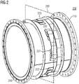
- FIG. 2 shows a perspective internal view of an example measuring section 210.
- the measuring section 210 includes an insulating liner within the inner diameter of the measuring section in order to insulate the fluid from the rest of the measuring section 210.
- a plurality of pairs of electromagnetic coils (shown as coils 220, 225, 227, and 222) are installed.
- the plurality of pairs of coils are installed along a first plane 290 of the measuring section 210, wherein the first plane 290 is perpendicular to the flow of the fluid in the measuring section 210.
- a diameter of the measuring section (310) is within a range of 1200 millimeters to 3200 millimeters.
- the plurality of pairs of electromagnetic coils includes one or more primary pairs of coils and one or more secondary pairs of coils.
- the transmitter 140 is capable of exciting the plurality of pairs of coils by providing one or more driving currents.
- the one or more primary pairs of coils upon excitation, generate one or more magnetic fields within the measuring section, for measuring the volumetric flow of fluid.
- the magnetic field strength at the center of the measuring section 310 is between .01 milli Tesla and 10 milli Tesla.
- the interaction of the magnetic fields and the conducting fluid flowing through the measuring section 210 generates a voltage which is then measured by one or more measuring electrodes.
- the generated voltage is proportional to the magnetic field and the velocity of the fluid and accordingly, based on the generated voltage, the velocity of the fluid can be determined.
- Relative to diamond coils as known in the state of the art the relative size of each coil from each pair of coils is small and accordingly each coil does not produce a magnetic field which covers the entire cross section of the measuring section 210.
- this issue is addressed by having a plurality of pairs of coils which generate a plurality of magnetic fields. Accordingly, the plurality of magnetic fields cover the majority of the cross section of the measuring section 210. Therefore, through the usage of the small coils (where each magnetic field generated by a corresponding pair of coils covers only a part of measuring section), the ease of construction of the electromagnetic flowmeter is improved and the overall cost of the electromagnetic flowmeter.
- the one or more secondary pairs of coils are capable of being excited independently in relation the one or more primary pairs of coils, and accordingly, during normal operation, the one or more secondary pairs of coils are not excited.
- the secondary pairs of coils are excited upon the detection of a predefined event, in order to improve magnetic field within the measuring section 210. This is further explained in relation to figure 3 .
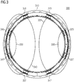
- Figure 3 shows front cross-sectional view of an example measuring section 310 with a plurality of pairs of coils (shown as coils 325 and 327, 315 and 317, 335 and 337, 345 and 347).
- the plurality of pairs of coils (325 and 327, 315 and 317, 335 and 337, 345 and 347) are mounted on the measuring section 310. While in the figure, four pairs of coils (325 and 327, 315 and 317, 335 and 337, 345 and 347) are shown, there may be other combinations involving at least two pairs of coils.
- the plurality of pairs of coils includes one or more primary pairs of coils (315 and 317, 335 and 337) and one or more secondary pairs of coils (325 and 327, 345 and 347).
- the primary pairs of coils include coils 335 and 337, and coils 315 and 317.
- Each pair of coils from the primary pairs of coils generates a corresponding magnetic field upon being excited by a driving current from a transmitter (not shown in the figure).
- the primary pair of coils 315 and 317 when excited generate the magnetic field 320.
- the pairs of coils 335 and 337 when excited generate the magnetic field 340.
- the transmitter 140 provides the driving current (or driving currents) to the primary pairs of coils to generate the magnetic fields (320 and 340). Additionally, the transmitter 140 is configured to detect a predefined event (or a plurality of predefined events). The predefined event (s) is indicative of a need for improving the magnetic fields within the measuring section 310.
- the transmitter 140 is configured to excite one or more secondary pairs of coils which then generate one or more additional magnetic fields (also referred to as secondary magnetic fields), shown in the figure as secondary magnetic fields 330 and 350.
- the one or more secondary pairs of coils (325 and 327, 345 and 347) are capable of measuring the one or more magnetic fields (320 and 340) generated by the one or more primary pairs of coils (315 and 317, 335 and 337), when not excited.
- the one or more secondary pairs of coils (325 and 327, 345 and 347) are capable of forming an electromagnetic circuit with the one or more primary pairs of coils (315 and 317, 335 and 337) and accordingly, due to the magnetic fields (320, 340) generated by the primary pairs of coils (315 and 317, 335 and 337), a voltage may be generated in the one or more secondary pairs of coils (325 and 327, 345 and 347). Accordingly, based on the magnitude of voltage generated across the secondary pairs of coils (325 and 327, 345 and 347), the strength of the magnetic fields generated by the one or more primary coils (315 and 317, 335 and 337) can be measured.
- the one or more secondary magnetic fields (330, 350) are capable of interacting with at least one magnetic field (320, 340) from the one or more magnetic fields (320, 340) generated by the one or more primary pairs of coils (315 and 317, 335 and 337), for improving at least one of a magnetic field homogeneity of the one or more magnetic fields (320, 340) and a magnetic gain of the at least one magnetic field (320, 340).
- the secondary pairs of coils (325 and 327, and 345 and 347) can generate additional magnetic fields (330 and 350) to tune the existing magnetic fields (320 and 340) to eliminate the bias and improve magnetic homogeneity. Accordingly, the magnetic fields within the measuring section 310 are improved and this enables better accuracy in measurement. Further examples in relation to the predefined event are provided below.
- the predefined event is associated with a measurement parameter of the electromagnetic flowmeter, wherein the measurement parameter is indicative of a measurement effectiveness of the electromagnetic flowmeter (100). This is explained in relation to figure 5 and 6 .
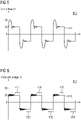
- Figure 5 illustrates excitation voltage applied across the primary pairs of coils, over a period of time.
- the magnitude of the voltage is shown along the vertical axis (i.e. Y-axis) and time is shown along the horizontal axis (i.e. X-axis).
- the excitation voltage also referred to as coil voltage
- the excitation voltage is a pulsed DC voltage provided by the transmitter 140, to excite the primary pairs of coils.
- a voltage also referred to measured voltage
- the measured voltage is proportional to the magnetic field and the flow velocity, and accordingly, similar to the excitation voltage, has alternating cycles and resembles the excitation voltage waveform 510. This is shown in figure 6 , where the measured voltage is shown as waveform 610 (which is similar to the waveform 510).
- the magnitude of the measured voltage is measured after the waveform has stabilized. Additionally, the magnitude is measured in both positive and negative phases of a cycle. For example, as shown in the figure 6 , the magnitudes are measured during time periods 615 and 625, 635 and 645, 655 and 665. During normal operation, after stabilization and removal of noise etc., the magnitude of the measured voltage during the positive phase (referred to as Uee+) and negative phase (Uee-), is same.
- the transmitter 140 checks the values of the measured voltage, during both phases of the measurement. However, when the values of the measured voltage don't match (i.e. the magnitude Uee+ is not equal to the magnitude of Uee-), the transmitter detects a potential abnormality. Sometimes, this may occur due to assembling or installing issues, dirt/wear of the coils, etc., while the flow velocity is constant. This may lead to accuracy problems. Accordingly, the predefined event is when the values of the measured voltage don't match (i.e. the magnitude Uee+ is not equal to the magnitude of Uee-) .
- the transmitter 140 When the transmitter 140 detects the above mentioned event, the transmitter utilizes the secondary pairs of coils (347 and 347, 325 and 327) to check the magnetic fields (320 and 340) generated by the primary pair of coils (315 and 317, 335 and 337) to evaluate if the deviation in the magnitudes of voltages (Uee+ and Uee-) come from a issue with the electromagnetic flowmeter or from a change in the flow profile of the fluid. If the magnetic fields (320 and 340) are inequal, the transmitter determines that the issue originates due to improper installation or due to degradation of the coils. Accordingly, to address this, the transmitter excites the secondary pairs of coils and/or adapts the driving current of the primary pairs of coils to adjust the magnetic fields and stabilize the measured voltage signal.
- secondary magnetic fields (330, 350) are generated.
- the secondary magnetic fields are capable of interacting with at least one magnetic field (320, 340) from the one or more magnetic fields (320, 340) generated by the one or more primary pairs of coils (315 and 317, 335 and 337), for improving at least one of a magnetic field homogeneity of the one or more magnetic fields (320, 340) and a magnetic gain of the at least one magnetic field (320, 340) .
- the predefined event is a periodic event with a frequency set during one of the calibration of the electromagnetic flowmeter and installation of the electromagnetic flowmeter.
- the electromagnetic flowmeter is power by a local power source (such as batteries) and accordingly, in order to conserve power, the secondary pairs of coils are inactive usually and only excited at certain intervals to ensure that the measurements performed using the magnetic fields generated by the primary pairs of coils are accurate. For example, once every hour, the secondary pair of coils are excited, and the measurements made with during this instance are compared with the measurements made when the secondary pairs of coils are unexcited.
- 'High accuracy' mode the overall magnetic field homogeneity and magnetic field strength is increased substantially and this allows for precise measurement If the measurements are equivalent or if no measurement issues (such as difference in Uee+ and Uee-) are detected, then the secondary pairs of coils are no longer excited and only the primary pair of coils remain excited, This is referred to as 'standby and control' mode.
- the electromagnetic flowmeter is installed on a fluid carrying channel for measuring the volumetric flow of a fluid flowing within the fluid carrying channel and the predefined event is associated with a condition of a process equipment.
- the fluid carrying channel is connected to at least one of an input and output valves of the process equipment. Accordingly, the secondary pairs of coils are excited based on the condition of the process equipment.
- the process equipment is a pump, and the secondary pairs of coils are excited only when the pump is at a certain load threshold.
- the electromagnetic flowmeter is able to fine tune the magnetic fields generated by the primary pairs of coils and thereby enables improved accuracy. Additionally, through the dynamic activation of the secondary pairs of coils, the electromagnetic flowmeter is more resilient to perturbations in flow profile of the fluid. Additionally, through the measurements of the magnetic fields generated by the primary pairs of coils using the secondary pairs of coils and through the dynamic excitation of the secondary pairs of coils, the electromagnetic flowmeter is able to adapt to the installation & operating conditions of the industrial facility. Additionally, this reduces the need for additional calibration.
- the current disclosure discloses an electromagnetic flowmeter which is capable of adapting the magnetic field within the measuring section of the electromagnetic flowmeter, and this improves the accuracy of the electromagnetic flowmeter since this enables the flowmeter to adapt to the conditions of the industrial facility. For example, this allows the flowmeter to be used in proximity to turns in the pipes and accordingly, the flowmeter does not need long inlet/outlet pipes (which is usually required for conventional flowmeters).
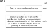
- the current disclosure describes a method 400 of operating an electromagnetic flowmeter for measuring a volumetric flow of a fluid.
- the electromagnetic flowmeter comprises a plurality of pairs of coils (315 and 317, 335 and 337, 325 and 327, 345 and 347) installed on a circumference of a measuring section 310 of the electromagnetic flowmeter 100.
- the plurality of pair of coils (315 and 317, 335 and 337, 325 and 327, 345 and 347) includes one or more primary pairs of coils (315 and 317, 335 and 337) for generating one or more magnetic fields (320, 340) within the measuring section 310, for measuring the volumetric flow of fluid and one or more secondary pairs of coils (325 and 327, 345 and 347) capable of being excited independently in relation the one or more primary pairs of coils (315 and 317, 335 and 337).
- the method 400 is performed by the electromagnetic flowmeter.
- the method 400 comprises detecting (410) an occurrence of a predefined event, wherein the predefined event is associated with one of process equipment, the one or more magnetic fields (320, 340) generated by the one or more primary pairs of coils (315 and 317, 335 and 337), and a predefined frequency set during one of the calibration of the electromagnetic flowmeter (100) and installation of the electromagnetic flowmeter (100).
- the method further comprises determining (420) at least one secondary pair of coils (325 and 327, 345 and 347) from the secondary pairs of coils (325 and 327, 345 and 347) and one or more parameters of a driving current associated with the at least one secondary pair of coils (325 and 327, 345 and 347) from the secondary pairs of coils (325 and 327, 345 and 347), for generating a secondary magnetic field (330, 350).
- the secondary magnetic field (330, 350) is capable of interacting with at least one magnetic field (320, 340) from the one or more magnetic fields (320, 340) generated by the one or more primary pairs of coils (315 and 317, 335 and 337), for improving at least one of a magnetic field homogeneity of the one or more magnetic fields (320, 340) and a magnetic gain of the at least one magnetic field (320, 340).
Landscapes
- Physics & Mathematics (AREA)
- Engineering & Computer Science (AREA)
- Power Engineering (AREA)
- Electromagnetism (AREA)
- Fluid Mechanics (AREA)
- General Physics & Mathematics (AREA)
- Measuring Volume Flow (AREA)
Priority Applications (5)
| Application Number | Priority Date | Filing Date | Title |
|---|---|---|---|
| EP21168578.9A EP4075103A1 (fr) | 2021-04-15 | 2021-04-15 | Débitmètre électromagnétique doté de paires de bobines primaire et secondaire |
| CN202280028604.XA CN117178171A (zh) | 2021-04-15 | 2022-04-08 | 具有初级和次级线圈对的电磁流量计 |
| PCT/EP2022/059416 WO2022218852A1 (fr) | 2021-04-15 | 2022-04-08 | Débitmètre électromagnétique avec paires de bobines primaire et secondaire |
| US18/286,678 US12644737B2 (en) | 2021-04-15 | 2022-04-08 | Electromagnetic flowmeter with primary and secondary pairs of coils |
| EP22719302.6A EP4275018B1 (fr) | 2021-04-15 | 2022-04-08 | Débitmètre électromagnétique doté de paires de bobines primaire et secondaire |
Applications Claiming Priority (1)
| Application Number | Priority Date | Filing Date | Title |
|---|---|---|---|
| EP21168578.9A EP4075103A1 (fr) | 2021-04-15 | 2021-04-15 | Débitmètre électromagnétique doté de paires de bobines primaire et secondaire |
Publications (1)
| Publication Number | Publication Date |
|---|---|
| EP4075103A1 true EP4075103A1 (fr) | 2022-10-19 |
Family
ID=75539172
Family Applications (2)
| Application Number | Title | Priority Date | Filing Date |
|---|---|---|---|
| EP21168578.9A Withdrawn EP4075103A1 (fr) | 2021-04-15 | 2021-04-15 | Débitmètre électromagnétique doté de paires de bobines primaire et secondaire |
| EP22719302.6A Active EP4275018B1 (fr) | 2021-04-15 | 2022-04-08 | Débitmètre électromagnétique doté de paires de bobines primaire et secondaire |
Family Applications After (1)
| Application Number | Title | Priority Date | Filing Date |
|---|---|---|---|
| EP22719302.6A Active EP4275018B1 (fr) | 2021-04-15 | 2022-04-08 | Débitmètre électromagnétique doté de paires de bobines primaire et secondaire |
Country Status (4)
| Country | Link |
|---|---|
| US (1) | US12644737B2 (fr) |
| EP (2) | EP4075103A1 (fr) |
| CN (1) | CN117178171A (fr) |
| WO (1) | WO2022218852A1 (fr) |
Families Citing this family (1)
| Publication number | Priority date | Publication date | Assignee | Title |
|---|---|---|---|---|
| EP4067832A1 (fr) * | 2021-03-31 | 2022-10-05 | Siemens Aktiengesellschaft | Débitmètre électromagnétique comportant une pluralité de bobines |
Citations (5)
| Publication number | Priority date | Publication date | Assignee | Title |
|---|---|---|---|---|
| US4503711A (en) * | 1983-09-30 | 1985-03-12 | Rosemount Inc. | Travelling wave flowmeter |
| WO1993015379A1 (fr) * | 1992-01-24 | 1993-08-05 | Marsh-Mcbirney, Inc. | Debitmetre a champ electromagnetique concentrique |
| WO1998052001A1 (fr) * | 1997-05-13 | 1998-11-19 | Hersey Measurement Company | Debitmetre electromagnetique |
| WO2014028450A1 (fr) * | 2012-08-14 | 2014-02-20 | Cidra Corporate Services Inc. | Tomographie à impédance magnétique-électrique modulée à profilage de flux |
| EP3184969A1 (fr) * | 2015-12-21 | 2017-06-28 | Proces-Data A/S | Débitmètre électromagnétique à électrodes multiples |
Family Cites Families (10)
| Publication number | Priority date | Publication date | Assignee | Title |
|---|---|---|---|---|
| US3490282A (en) | 1966-07-28 | 1970-01-20 | Tokyo Shibaura Electric Co | Induction liquid flowmeters |
| DE1911556A1 (de) * | 1969-03-07 | 1970-09-24 | Krohne Fa Ludwig | Induktiver Stroemungsmesser |
| JPS62188910A (ja) * | 1986-02-14 | 1987-08-18 | Aichi Tokei Denki Co Ltd | 電磁流量計 |
| JPH0510796A (ja) | 1991-07-01 | 1993-01-19 | Toshiba Corp | 電磁流量計 |
| RU2343423C1 (ru) | 2007-05-03 | 2009-01-10 | ОАО "НИИТеплоприбор" | Электромагнитный расходомер |
| US9021890B2 (en) * | 2012-09-26 | 2015-05-05 | Rosemount Inc. | Magnetic flowmeter with multiple coils |
| DE102014113404A1 (de) | 2014-09-17 | 2016-03-17 | Endress + Hauser Flowtec Ag | Magnetisch-induktives Durchflussmessgerät mit einem Vierspulen- Magnetsystem |
| GB2534337B (en) | 2014-09-29 | 2017-10-18 | Iphase Ltd | Method and apparatus for monitoring of the multiphase flow in a pipe |
| CN112146715B (zh) | 2020-08-26 | 2022-09-06 | 沈阳兰申电器有限公司 | 一种具有符合权重分布磁场的电磁流量计的励磁方法 |
| EP4067832A1 (fr) | 2021-03-31 | 2022-10-05 | Siemens Aktiengesellschaft | Débitmètre électromagnétique comportant une pluralité de bobines |
-
2021
- 2021-04-15 EP EP21168578.9A patent/EP4075103A1/fr not_active Withdrawn
-
2022
- 2022-04-08 EP EP22719302.6A patent/EP4275018B1/fr active Active
- 2022-04-08 WO PCT/EP2022/059416 patent/WO2022218852A1/fr not_active Ceased
- 2022-04-08 US US18/286,678 patent/US12644737B2/en active Active
- 2022-04-08 CN CN202280028604.XA patent/CN117178171A/zh active Pending
Patent Citations (5)
| Publication number | Priority date | Publication date | Assignee | Title |
|---|---|---|---|---|
| US4503711A (en) * | 1983-09-30 | 1985-03-12 | Rosemount Inc. | Travelling wave flowmeter |
| WO1993015379A1 (fr) * | 1992-01-24 | 1993-08-05 | Marsh-Mcbirney, Inc. | Debitmetre a champ electromagnetique concentrique |
| WO1998052001A1 (fr) * | 1997-05-13 | 1998-11-19 | Hersey Measurement Company | Debitmetre electromagnetique |
| WO2014028450A1 (fr) * | 2012-08-14 | 2014-02-20 | Cidra Corporate Services Inc. | Tomographie à impédance magnétique-électrique modulée à profilage de flux |
| EP3184969A1 (fr) * | 2015-12-21 | 2017-06-28 | Proces-Data A/S | Débitmètre électromagnétique à électrodes multiples |
Also Published As
| Publication number | Publication date |
|---|---|
| US12644737B2 (en) | 2026-06-02 |
| EP4275018C0 (fr) | 2024-09-11 |
| WO2022218852A1 (fr) | 2022-10-20 |
| EP4275018A1 (fr) | 2023-11-15 |
| EP4275018B1 (fr) | 2024-09-11 |
| US20240200994A1 (en) | 2024-06-20 |
| CN117178171A (zh) | 2023-12-05 |
Similar Documents
| Publication | Publication Date | Title |
|---|---|---|
| EP0336615B1 (fr) | Débitmètre électromagnétique capable pour la mesure simultanée du débit et de la conductivité d'un fluide | |
| EP0416866B1 (fr) | Débitmètre électromagnétique utilisant des champs magnétiques de fréquences différentes | |
| RU2584069C2 (ru) | Электромагнитный расходомер с изменяемой частотой (варианты) | |
| US9021890B2 (en) | Magnetic flowmeter with multiple coils | |
| US9696188B2 (en) | Magnetic flowmeter with automatic adjustment based on sensed complex impedance | |
| JP2009258125A (ja) | 流体用の磁気誘導式流量測定計および磁気誘導式流量測定方法 | |
| US12298160B2 (en) | Method of operating a magnetically-inductive flowmeter | |
| EP4275018B1 (fr) | Débitmètre électromagnétique doté de paires de bobines primaire et secondaire | |
| JP4908752B2 (ja) | 測定機器の運転方法 | |
| EP4271968B1 (fr) | Débitmètre électromagnétique comportant une pluralité de bobines | |
| EP2259028B1 (fr) | Débitmètre électromagnétique | |
| JP4386855B2 (ja) | 磁気誘導性流量計の作動方法 | |
| US20200217698A1 (en) | Magnetic flowmeter with media conductivity measurement | |
| CN100545587C (zh) | 磁感应流量计 | |
| US7174256B2 (en) | Magnetoinductive flowmeter and measuring method for a magnetoinductive flowmeter | |
| EP3770560A1 (fr) | Ensemble débitmètre magnétique avec capacité d'élimination d'impulsions transitoires | |
| WO2010121631A1 (fr) | Débitmètre électromagnétique et procédé de fonctionnement de celui-ci | |
| US6834555B2 (en) | Magnetoinductive flow measuring method | |
| JP2751269B2 (ja) | 電磁流量計 | |
| JPS6111611Y2 (fr) | ||
| JPH0835867A (ja) | 電磁流量計 | |
| US11493373B2 (en) | Clamp on electromagnetic flowmeter for determining flow in a pipe using leakage current compensation | |
| CN121230825A (zh) | 用于运行磁感应流量测量仪的方法及磁感应流量测量仪 | |
| JP2016200415A (ja) | 電磁流量計及び電磁流量計の流量測定方法 | |
| Jiang et al. | Simulation Research on Unit Element Calibration Method Based Geometry Discretization |
Legal Events
| Date | Code | Title | Description |
|---|---|---|---|
| PUAI | Public reference made under article 153(3) epc to a published international application that has entered the european phase |
Free format text: ORIGINAL CODE: 0009012 |
|
| STAA | Information on the status of an ep patent application or granted ep patent |
Free format text: STATUS: THE APPLICATION HAS BEEN PUBLISHED |
|
| AK | Designated contracting states |
Kind code of ref document: A1 Designated state(s): AL AT BE BG CH CY CZ DE DK EE ES FI FR GB GR HR HU IE IS IT LI LT LU LV MC MK MT NL NO PL PT RO RS SE SI SK SM TR |
|
| STAA | Information on the status of an ep patent application or granted ep patent |
Free format text: STATUS: THE APPLICATION IS DEEMED TO BE WITHDRAWN |
|
| 18D | Application deemed to be withdrawn |
Effective date: 20230420 |