EP4067893A1 - Capteur de fluide pour détecter les propriétés d'un fluide comprenant un résonateur mécanique à diapason - Google Patents
Capteur de fluide pour détecter les propriétés d'un fluide comprenant un résonateur mécanique à diapason Download PDFInfo
- Publication number
- EP4067893A1 EP4067893A1 EP21305414.1A EP21305414A EP4067893A1 EP 4067893 A1 EP4067893 A1 EP 4067893A1 EP 21305414 A EP21305414 A EP 21305414A EP 4067893 A1 EP4067893 A1 EP 4067893A1
- Authority
- EP
- European Patent Office
- Prior art keywords
- tine
- fluid
- fluid sensor
- electrodes
- tuning fork
- Prior art date
- Legal status (The legal status is an assumption and is not a legal conclusion. Google has not performed a legal analysis and makes no representation as to the accuracy of the status listed.)
- Pending
Links
Images


Classifications
-
- G—PHYSICS
- G01—MEASURING; TESTING
- G01N—INVESTIGATING OR ANALYSING MATERIALS BY DETERMINING THEIR CHEMICAL OR PHYSICAL PROPERTIES
- G01N29/00—Investigating or analysing materials by the use of ultrasonic, sonic or infrasonic waves; Visualisation of the interior of objects by transmitting ultrasonic or sonic waves through the object
- G01N29/02—Analysing fluids
- G01N29/036—Analysing fluids by measuring frequency or resonance of acoustic waves
-
- G—PHYSICS
- G01—MEASURING; TESTING
- G01N—INVESTIGATING OR ANALYSING MATERIALS BY DETERMINING THEIR CHEMICAL OR PHYSICAL PROPERTIES
- G01N27/00—Investigating or analysing materials by the use of electric, electrochemical, or magnetic means
- G01N27/02—Investigating or analysing materials by the use of electric, electrochemical, or magnetic means by investigating impedance
- G01N27/04—Investigating or analysing materials by the use of electric, electrochemical, or magnetic means by investigating impedance by investigating resistance
- G01N27/06—Investigating or analysing materials by the use of electric, electrochemical, or magnetic means by investigating impedance by investigating resistance of a liquid
- G01N27/07—Construction of measuring vessels; Electrodes therefor
-
- G—PHYSICS
- G01—MEASURING; TESTING
- G01D—MEASURING NOT SPECIALLY ADAPTED FOR A SPECIFIC VARIABLE; ARRANGEMENTS FOR MEASURING TWO OR MORE VARIABLES NOT COVERED IN A SINGLE OTHER SUBCLASS; TARIFF METERING APPARATUS; MEASURING OR TESTING NOT OTHERWISE PROVIDED FOR
- G01D5/00—Mechanical means for transferring the output of a sensing member; Means for converting the output of a sensing member to another variable where the form or nature of the sensing member does not constrain the means for converting; Transducers not specially adapted for a specific variable
- G01D5/12—Mechanical means for transferring the output of a sensing member; Means for converting the output of a sensing member to another variable where the form or nature of the sensing member does not constrain the means for converting; Transducers not specially adapted for a specific variable using electric or magnetic means
-
- G—PHYSICS
- G01—MEASURING; TESTING
- G01N—INVESTIGATING OR ANALYSING MATERIALS BY DETERMINING THEIR CHEMICAL OR PHYSICAL PROPERTIES
- G01N27/00—Investigating or analysing materials by the use of electric, electrochemical, or magnetic means
- G01N27/02—Investigating or analysing materials by the use of electric, electrochemical, or magnetic means by investigating impedance
- G01N27/026—Dielectric impedance spectroscopy
-
- G—PHYSICS
- G01—MEASURING; TESTING
- G01N—INVESTIGATING OR ANALYSING MATERIALS BY DETERMINING THEIR CHEMICAL OR PHYSICAL PROPERTIES
- G01N29/00—Investigating or analysing materials by the use of ultrasonic, sonic or infrasonic waves; Visualisation of the interior of objects by transmitting ultrasonic or sonic waves through the object
- G01N29/02—Analysing fluids
- G01N29/022—Fluid sensors based on microsensors, e.g. quartz crystal-microbalance [QCM], surface acoustic wave [SAW] devices, tuning forks, cantilevers, flexural plate wave [FPW] devices
-
- G—PHYSICS
- G01—MEASURING; TESTING
- G01N—INVESTIGATING OR ANALYSING MATERIALS BY DETERMINING THEIR CHEMICAL OR PHYSICAL PROPERTIES
- G01N29/00—Investigating or analysing materials by the use of ultrasonic, sonic or infrasonic waves; Visualisation of the interior of objects by transmitting ultrasonic or sonic waves through the object
- G01N29/22—Details, e.g. general constructional or apparatus details
- G01N29/222—Constructional or flow details for analysing fluids
-
- G—PHYSICS
- G01—MEASURING; TESTING
- G01N—INVESTIGATING OR ANALYSING MATERIALS BY DETERMINING THEIR CHEMICAL OR PHYSICAL PROPERTIES
- G01N29/00—Investigating or analysing materials by the use of ultrasonic, sonic or infrasonic waves; Visualisation of the interior of objects by transmitting ultrasonic or sonic waves through the object
- G01N29/22—Details, e.g. general constructional or apparatus details
- G01N29/24—Probes
- G01N29/2437—Piezoelectric probes
-
- G—PHYSICS
- G01—MEASURING; TESTING
- G01N—INVESTIGATING OR ANALYSING MATERIALS BY DETERMINING THEIR CHEMICAL OR PHYSICAL PROPERTIES
- G01N29/00—Investigating or analysing materials by the use of ultrasonic, sonic or infrasonic waves; Visualisation of the interior of objects by transmitting ultrasonic or sonic waves through the object
- G01N29/22—Details, e.g. general constructional or apparatus details
- G01N29/24—Probes
- G01N29/2475—Embedded probes, i.e. probes incorporated in objects to be inspected
-
- G—PHYSICS
- G01—MEASURING; TESTING
- G01N—INVESTIGATING OR ANALYSING MATERIALS BY DETERMINING THEIR CHEMICAL OR PHYSICAL PROPERTIES
- G01N29/00—Investigating or analysing materials by the use of ultrasonic, sonic or infrasonic waves; Visualisation of the interior of objects by transmitting ultrasonic or sonic waves through the object
- G01N29/22—Details, e.g. general constructional or apparatus details
- G01N29/32—Arrangements for suppressing undesired influences, e.g. temperature or pressure variations, compensating for signal noise
- G01N29/326—Arrangements for suppressing undesired influences, e.g. temperature or pressure variations, compensating for signal noise compensating for temperature variations
-
- G—PHYSICS
- G01—MEASURING; TESTING
- G01N—INVESTIGATING OR ANALYSING MATERIALS BY DETERMINING THEIR CHEMICAL OR PHYSICAL PROPERTIES
- G01N33/00—Investigating or analysing materials by specific methods not covered by groups G01N1/00 - G01N31/00
- G01N33/26—Oils; Viscous liquids; Paints; Inks
- G01N33/28—Oils, i.e. hydrocarbon liquids
-
- H—ELECTRICITY
- H03—ELECTRONIC CIRCUITRY
- H03H—IMPEDANCE NETWORKS, e.g. RESONANT CIRCUITS; RESONATORS
- H03H9/00—Networks comprising electromechanical or electro-acoustic elements; Electromechanical resonators
- H03H9/15—Constructional features of resonators consisting of piezoelectric or electrostrictive material
- H03H9/21—Crystal tuning forks
-
- G—PHYSICS
- G01—MEASURING; TESTING
- G01N—INVESTIGATING OR ANALYSING MATERIALS BY DETERMINING THEIR CHEMICAL OR PHYSICAL PROPERTIES
- G01N11/00—Investigating flow properties of materials, e.g. viscosity, plasticity; Analysing materials by determining flow properties
- G01N11/10—Investigating flow properties of materials, e.g. viscosity, plasticity; Analysing materials by determining flow properties by moving a body within the material
- G01N11/16—Investigating flow properties of materials, e.g. viscosity, plasticity; Analysing materials by determining flow properties by moving a body within the material by measuring damping effect upon oscillatory body
-
- G—PHYSICS
- G01—MEASURING; TESTING
- G01N—INVESTIGATING OR ANALYSING MATERIALS BY DETERMINING THEIR CHEMICAL OR PHYSICAL PROPERTIES
- G01N2291/00—Indexing codes associated with group G01N29/00
- G01N2291/02—Indexing codes associated with the analysed material
- G01N2291/022—Liquids
- G01N2291/0226—Oils, e.g. engine oils
-
- G—PHYSICS
- G01—MEASURING; TESTING
- G01N—INVESTIGATING OR ANALYSING MATERIALS BY DETERMINING THEIR CHEMICAL OR PHYSICAL PROPERTIES
- G01N2291/00—Indexing codes associated with group G01N29/00
- G01N2291/02—Indexing codes associated with the analysed material
- G01N2291/028—Material parameters
- G01N2291/02818—Density, viscosity
-
- G—PHYSICS
- G01—MEASURING; TESTING
- G01N—INVESTIGATING OR ANALYSING MATERIALS BY DETERMINING THEIR CHEMICAL OR PHYSICAL PROPERTIES
- G01N2291/00—Indexing codes associated with group G01N29/00
- G01N2291/02—Indexing codes associated with the analysed material
- G01N2291/028—Material parameters
- G01N2291/02863—Electric or magnetic parameters
-
- G—PHYSICS
- G01—MEASURING; TESTING
- G01N—INVESTIGATING OR ANALYSING MATERIALS BY DETERMINING THEIR CHEMICAL OR PHYSICAL PROPERTIES
- G01N2291/00—Indexing codes associated with group G01N29/00
- G01N2291/04—Wave modes and trajectories
- G01N2291/042—Wave modes
- G01N2291/0427—Flexural waves, plate waves, e.g. Lamb waves, tuning fork, cantilever
-
- G—PHYSICS
- G01—MEASURING; TESTING
- G01N—INVESTIGATING OR ANALYSING MATERIALS BY DETERMINING THEIR CHEMICAL OR PHYSICAL PROPERTIES
- G01N9/00—Investigating density or specific gravity of materials; Analysing materials by determining density or specific gravity
- G01N9/002—Investigating density or specific gravity of materials; Analysing materials by determining density or specific gravity using variation of the resonant frequency of an element vibrating in contact with the material submitted to analysis
-
- G—PHYSICS
- G01—MEASURING; TESTING
- G01N—INVESTIGATING OR ANALYSING MATERIALS BY DETERMINING THEIR CHEMICAL OR PHYSICAL PROPERTIES
- G01N9/00—Investigating density or specific gravity of materials; Analysing materials by determining density or specific gravity
- G01N9/24—Investigating density or specific gravity of materials; Analysing materials by determining density or specific gravity by observing the transmission of wave or particle radiation through the material
Definitions
- the invention relates to a fluid sensor for sensing properties of a fluid comprising a tuning fork mechanical resonator.
- Fluid sensors are known in the art and find their application in industrial machineries or transportation vehicles like construction equipment, agriculture vehicles, hydraulic systems, windmills or compressors. They are used to monitor one or more fluid parameters, like viscosity, density, dielectric constant or conductivity that are used to determine the quality of the fluid.
- the fluids can be oil, like non-electrically conductive oil, e.g. engine oil, transmission and axle oil, gear oil, power steering oil, hydraulic fluid or the like.
- Each application involves particular conditions like a temperature range, viscosity condition and mechanical requirements.
- Such a fluid sensor is known from US 2006 218996 A1 which comprises a resonator with a quartz tuning fork and electrodes on the tines.
- Such a resonator deforms upon application of a voltage and reciprocally electrically polarizes under the action of mechanical stress.
- the two tines oscillate and generate a response indicative of the physicochemical and electrical properties of the fluid wherein the fluid sensor is immersed.
- the fluid sensor comprises a tuning fork mechanical resonator.
- the tuning fork mechanical resonator comprises a base and at least one tine projecting from the base along a longitudinal direction of the at least one tine.
- the base and the at least one tine are formed in a piezoelectric material.
- the at least one tine comprises at least two electrodes configured to be exposed to the fluid.
- the piezoelectric material comprises lithium tantalate.
- lithium tantalate Compared to other piezoelectric materials, lithium tantalate provides mechanical properties that render the tuning fork mechanical resonator, and thus the fluid sensor, more robust. Thus, a more reliable fluid sensor can be provided. In addition, lithium tantalate has the advantage of being chemically stable so that the sensors lifetime can be extended.
- the fluid sensor can be further improved according to various advantageous embodiments.
- the embodiments are disclosed in the dependent claims.
- the tuning fork mechanical resonator can comprise two tines projecting from the base along a longitudinal direction of the two tines.
- the electrodes can be provided on or over a surface of the tine(s) or are at least partially embedded in the tine(s).
- Such electrode arrangement allows generating larger electric fields outside the piezoelectric material. Hence, the influence of the piezoelectric material on the measures of the fluid parameters can be reduced while measuring the properties of the fluid. Furthermore, this arrangement allows determining the electrical resistivity of the fluid.
- At least one of the electrodes can be provided on a surface of the lithium tantalate having a crystal cut angle comprised between 110 and 140 degrees on rotated Y-cut about the X-axis.
- the response of the fluid sensor is less sensitive to temperature. It therefore allows the use of the fluid sensor over an extended temperature ranges.
- each tine can have a substantially rectangular cross-section and comprises four electrodes, wherein each electrode is provided on or over a different face of each tine.
- This electrode arrangement can improve the sensitivity of the device.
- each electrode can be further provided on or over the base of the tuning fork mechanical resonator.
- This electrode arrangement also allows improving the sensitivity of the device. Indeed, such electrodes have the same tine excitation than in the case wherein the electrodes are only provided on or over the tines.
- each electrode can have a substantially oblong, in particular rectangular, shape, and a length along the longitudinal direction of the tine(s) of a portion of the electrode provided on or over a face of the tine can be comprised between 3 mm and 10 mm.
- the electrodes can be provided only on or over the tines. In a variant, the electrodes can also be provided on or over the tines, and, at least partially on or over the base. In both cases, according to the present invention, the length of the portion of the electrode provided on or over the tine(s) is comprised between 3 to 10 mm.
- the length of the tine(s) is indeed great enough to counter the shear forces induced by the high viscosity fluid, like oil.
- the tines are excited by piezoelectric effect thanks to large enough electrodes.
- a width of each tine along a direction transversal to a longitudinal extension of the tine(s) from the base can be comprised between 0,5 mm and 2 mm.
- the enlarged width of the tines renders the tines more resistant to mechanical stress in comparison with of the resonators in the art. Hence, the robustness of the fluid sensor is improved, which increase its lifetime and reliability.
- the length of the tuning fork mechanical resonator from the base to a free-end of each tine can be comprised between 6 mm and 30 mm, in particular between 10 mm and 13 mm.
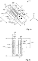
- Figure 1a illustrates a fluid sensor 1 comprising a tuning fork mechanical resonator 3 according to a first embodiment of the invention.
- the fluid sensor 1 can be mounted to a support which is not shown in Figure 1a , so as to be maintained in a fluid according to known assembly methods. In use, the fluid sensor 1 is at least partially immersed in a fluid for sensing its properties.
- the fluid can be an oil for industrial machines or for transportation vehicles.
- the tuning fork mechanical resonator 3 comprises a body 5 having a length L1 from one first free-end 7 until opposite second free-ends 9A, 9B along the X-axis of the Cartesian coordinates illustrated in Figure 1a .
- the body 5 comprises a base 11, extending along the X-axis of the Cartesian coordinates, from the free-end 7 to a junction region 13 of the body 5.
- two tines 15A, 15B extend distinctly from each other until their corresponding free-ends 9A, 9B along a longitudinal direction of the tines 15A, 15B.
- only one single tine can extend from the junction region 13 of the body 5 of the tuning fork mechanical resonator 3.
- three tines or more can extend from the junction region 13 of the body 5 of the tuning fork mechanical resonator 3.
- the two tines 15A, 15B project from the base 11 along the X-axis of the Cartesian coordinate.
- the longitudinal direction of the tines 15A, 15B is thus parallel to the X-axis of the Cartesian coordinate shown in Figure 1a .
- the tines 15A, 15B have a rectangular cross-section.
- a cross-section of the tines corresponds to the cross-section of a parallelepiped.
- the tines 15A, 15B are symmetrical to each other with respect to the X-axis of the Cartesian coordinates. In a variant, the tines 15A, 15B can be asymmetrical.
- the length L2 shown in Figure 2 represents the length between the junction region 13 and the free-ends 9A, 9B, i.e. L2 indicates the length of the tines 15A, 15B.
- Each tine 15A, 15B has a width L3.
- the dimensions L1 to L3 are further described hereafter in reference to Table 1.
- Each tine 15A, 15B is provided with electrodes 17A-B, 19A-B.
- the electrodes 17A-B, 19A-B have an oblong shape of length L4 along the longitudinal direction of the two tines 15A, 15B from the base 11, i.e. along the X-axis of the Cartesian coordinate.
- the electrodes 17A-B, 19A-B can have a rectangular shape.
- the single tine can be provided with two electrodes on or over a surface of the single tine, or, at least partially embedded in the single tine.
- two electrodes 17A-B are provided on or over a surface 21A (respectively a surface 21B) of the tine 15A (respectively the tine 15B).
- the electrodes 17A, 17B, 19A, 19B can be at least partially embedded in the tines 15A, 15B.
- the electrodes 170A-B, 190A-B are extended along the longitudinal direction of the tines 15A, 15B so as to be further provided on or over the base 11 of the tuning fork mechanical resonator 3.
- the length L4 corresponds to the length of the portion of each electrodes 170A-B, 190A-B provided on or over the tines 15A, 15B. In other words, in the second embodiment, the length L4 does not correspond to the total length of each electrodes 170A-B, 190A-B.
- the length L4 represents the length of a portion of the electrodes 17A-B, 170A-B, 19A-B, 190A-B on or over the tines 15A, 15B, i.e. the length of a portion of the electrodes 17A-B, 170A-B, 19A-B, 190A-B comprises between the junction region 13 and the free-ends 9A, 9B of the tines 15A, 15B.
- the length L4 further corresponds to the total length of the electrodes 17A-B, 19A-B, while in the second embodiment of Figure 1b , the length L4 only corresponds to a portion of the electrodes 170A-B, 190A-B.
- the electrodes 17A, 19A are formed by a noble layer NB provided on or over the surface 21A (respectively the surface 21B) of the tine 15A (respectively the tine 15B).
- the noble layer NB is a layer of gold.
- the noble layer NB has a thickness t1 comprised between 10nm and 600nm. In particular, the noble layer NB has a thickness of 200nm.
- a thin adhesion layer of chromium or titanium of thickness t2 can be provided underneath the noble layer NB, and, on or above the surfaces 21A, 21B.
- Such adhesion layer can have a thickness comprises between 5 and 40 nm.
- An adhesion layer improves the adhesion of the noble layer NB on the piezoelectric material of the tines 15A, 15B. Thereby, it improves the robustness of the layer stack of the fluid sensor 1. Hence, a delamination or damage due to chemical or mechanical stress (like thermal shocks, vibrations, mechanical shock%) can be reduced.
- the electrodes 17A, 17B are in electrical connection with a common first contact pad 23 through respective conductive paths (e.g. leads) 25A, 25B and are therefore in common electrical communication with each other.
- the electrodes 19A, 19B are in electrical connection with a common first contact pad 27 through respective conductive paths (e.g. leads) 29A, 29B and are therefore in common electrical connection with each other.
- the electrode 17A located on the tine 15A, is electrically connected to the electrode 17B located on the tine 15B and to the contact pad 23.
- the electrode 19A located on the tine 15A, is electrically connected to the electrode 19B located on the tine 15B and to the contact pad 27.
- the contact pads 23, 27 are used to electrically connect the electrodes 17A-B, 19A-B to a control unit (not represented) of the fluid sensor 1.
- FIGS 3 and 4 illustrate two embodiments of electrodes arrangement according to the present invention.
- each tine 15A, 15B comprises two electrodes 17A-B, 19A-B.
- An electrode 17A is provided on or over the surface 21A of the tine 15A.
- An electrode 17B is provided on or over the surface 31A of the tine 15B.
- An electrode 19A is provided on or over a surface 31A of the tine 15A.
- An electrode 19B is provided on or over the surface 21B of the tine 15B.
- the surfaces 31A, 31B are opposite to the surfaces 21A, 21B along the Y-axis of the Cartesian coordinate.
- the single tine could also be provided with two electrodes on or over opposite surfaces of the single tine.
- each tine 15A, 15B comprises four electrodes 17A-D 19A-D.
- the electrodes 17A-B and 17C-D can be connected or not.
- the electrodes 19A-B and 19C-D can be connected or not.
- Each electrode 17A-B 19A-B, 17C-D, 19C-D is provided on or over a different face 21A-31A, 21B-31B, 39B-37B, 37A-39A of each tine 15A, 15B.
- the surface 37A-B is opposite to the surface 39A-B along the Y-axis of the Cartesian coordinate.
- the single tine could also be provided with four electrodes on or over a surface of the single tine.
- the electrodes 17A, 17B, 19A, 19B are configured to be exposed to the fluid in which the sensor 1 is immersed. Hence, the electrodes 17A, 17B, 19A, 19B have a direct surface contact with the fluid in which the fluid sensor 1 is immersed.
- each tines 15A, 15B is capable of displacement in a fluid relative to the base 11 of the tuning fork mechanical resonator 3.
- the pair of tines 15A, 15B can thus also be referred to as vibrating arms of the tuning fork mechanical resonator 3.
- the oscillation of the tines 15A, 15B allows generating a response indicative of the physicochemical and electrical properties of the fluid wherein the fluid sensor 1 is immersed.
- the electrodes 17A, 17B, 19A, 19B (17C-17D, 19C-19D) are exposed to the fluid, and electric fields can be generated within and outside the piezoelectric material of the tuning fork mechanical resonator 3.
- the fluid sensor 1 is able to measure the electrical resistivity of the fluid, in addition of the viscosity, the density and the dielectric constant.
- the electrode (17A-B, 19A-B, 17C-17D, 19C-19D) arrangement shown in Figure 4 allows generating an even larger electric field outside the piezoelectric material of the tuning fork mechanical resonator 3 than in the embodiments of Figures 1a, 1b , 2 and 3 , which renders the fluid sensor 1 even more adapted for measuring the electrical resistivity of the fluid.
- the body 5 of the tuning fork mechanical resonator 3 comprises lithium tantalate (LiTaO3) as piezoelectric material.
- Lithium tantalate exhibits a piezoelectric effect, and can thus be used for a tuning fork mechanical resonator. Because of its advantageous mechanical properties, the use of lithium tantalate renders the fluid sensor 1 more robust compared to tuning fork mechanical resonator made of lithium niobate or quartz. Hence, the reliability of the fluid sensor 1 is improved.
- the lithium tantalate furthermore is chemically stable.
- the lifetime of such fluid sensor 1 can advantageously be increased with respect to the tuning fork devices known from the state of the art.
- the surface 21A of the piezoelectric material on or over which the electrodes 17A-B, 19A-B are provided has a crystal cut angle comprised between 110 and 140 degrees on rotated Y-cut about the X-axis, the tine strain being along the X-axis.
- the piezoelectric effect provided by the lithium tantalate (LiTaO 3 ) is less temperature dependent compared to lithium niobiate (LiNbO 3 ).
- the fluid sensor 1 can be used in broad ranges of temperature and viscosity conditions.
- the fluid sensor 1 comprising lithium tantalate as piezoelectric material has an improved lifetime and reliability in particular in extended temperature ranges and/or harsh environments than the known fluid sensors with a resonator made of quartz.
- the body 5 can comprises different materials, thus a combination of lithium tantalate and one or more of quartz, zirconate titanate (PZT), lithium niobiate, berlinite or zinc oxide, according to the desired application.
- a tine can be made from multilayers of different materials comprising a non-piezoelectric material like silicon nitride, silicon carbide or silicon oxide, according to the desired application.
- the fluid sensor 1 has the following dimensions (see Table 1 below).
- the dimensions L1 to L4 in Table 1 corresponds to the dimensions previously described with respect to Figures 1a and 1b .
- the larger dimensions L1-L4 of the fluid sensor 1 comprising lithium tantalate provide, in addition of realizing a more robust fluid sensor 1 than known tuning forks of smaller size, a fluid sensor 1 exhibiting a resonance signal of better quality in high viscosity fluid condition.
- the size of the fluid sensor 1 is indeed large enough for avoiding that the resonance signal is damped, in particular in high viscosity fluid condition, i.e. between 50cP and up to 20.000 cP.
Landscapes
- Physics & Mathematics (AREA)
- Chemical & Material Sciences (AREA)
- Health & Medical Sciences (AREA)
- General Physics & Mathematics (AREA)
- Life Sciences & Earth Sciences (AREA)
- Immunology (AREA)
- Analytical Chemistry (AREA)
- Biochemistry (AREA)
- General Health & Medical Sciences (AREA)
- Pathology (AREA)
- Acoustics & Sound (AREA)
- Chemical Kinetics & Catalysis (AREA)
- Electrochemistry (AREA)
- Engineering & Computer Science (AREA)
- Spectroscopy & Molecular Physics (AREA)
- Crystallography & Structural Chemistry (AREA)
- Oil, Petroleum & Natural Gas (AREA)
- Food Science & Technology (AREA)
- Medicinal Chemistry (AREA)
- General Chemical & Material Sciences (AREA)
- Piezo-Electric Or Mechanical Vibrators, Or Delay Or Filter Circuits (AREA)
- Investigating Or Analyzing Materials By The Use Of Ultrasonic Waves (AREA)
Priority Applications (4)
| Application Number | Priority Date | Filing Date | Title |
|---|---|---|---|
| EP21305414.1A EP4067893A1 (fr) | 2021-03-31 | 2021-03-31 | Capteur de fluide pour détecter les propriétés d'un fluide comprenant un résonateur mécanique à diapason |
| JP2022051554A JP7335386B2 (ja) | 2021-03-31 | 2022-03-28 | 音叉型機械共振器を備える、流体の特性を感知するための流体センサ |
| CN202210311156.6A CN115143997A (zh) | 2021-03-31 | 2022-03-28 | 包括音叉机械谐振器的、感测流体特性的流体传感器 |
| US17/710,452 US11921073B2 (en) | 2021-03-31 | 2022-03-31 | Fluid sensor for sensing properties of a fluid comprising a tuning fork mechanical resonator |
Applications Claiming Priority (1)
| Application Number | Priority Date | Filing Date | Title |
|---|---|---|---|
| EP21305414.1A EP4067893A1 (fr) | 2021-03-31 | 2021-03-31 | Capteur de fluide pour détecter les propriétés d'un fluide comprenant un résonateur mécanique à diapason |
Publications (1)
| Publication Number | Publication Date |
|---|---|
| EP4067893A1 true EP4067893A1 (fr) | 2022-10-05 |
Family
ID=75588149
Family Applications (1)
| Application Number | Title | Priority Date | Filing Date |
|---|---|---|---|
| EP21305414.1A Pending EP4067893A1 (fr) | 2021-03-31 | 2021-03-31 | Capteur de fluide pour détecter les propriétés d'un fluide comprenant un résonateur mécanique à diapason |
Country Status (4)
| Country | Link |
|---|---|
| US (1) | US11921073B2 (fr) |
| EP (1) | EP4067893A1 (fr) |
| JP (1) | JP7335386B2 (fr) |
| CN (1) | CN115143997A (fr) |
Families Citing this family (1)
| Publication number | Priority date | Publication date | Assignee | Title |
|---|---|---|---|---|
| CN119164827B (zh) * | 2024-08-02 | 2025-09-30 | 福建师范大学 | 基于压电或逆压电效应的高精度力电耦合谐振音叉传感器 |
Citations (4)
| Publication number | Priority date | Publication date | Assignee | Title |
|---|---|---|---|---|
| JPS57124238A (en) * | 1981-01-23 | 1982-08-03 | Murata Mfg Co Ltd | Humidity sensor |
| JP2001324332A (ja) * | 2000-05-16 | 2001-11-22 | Fujitsu Media Device Kk | 圧電ジャイロ |
| US20060218996A1 (en) | 2002-10-18 | 2006-10-05 | Symyx Technologies, Inc. | Machine fluid sensor |
| US20130134981A1 (en) * | 2011-11-30 | 2013-05-30 | Baker Hughes Incorporated | Crystal sensor made by ion implantation |
Family Cites Families (13)
| Publication number | Priority date | Publication date | Assignee | Title |
|---|---|---|---|---|
| JPS52114246A (en) * | 1976-03-22 | 1977-09-24 | Toshiba Corp | Elastic surface wave device |
| JPH1164004A (ja) * | 1997-06-13 | 1999-03-05 | Denso Corp | 角速度センサと角速度センサ装置 |
| JP2000009469A (ja) | 1998-06-18 | 2000-01-14 | Fujitsu Ltd | 圧電ジャイロおよびその駆動方法 |
| JP2000324332A (ja) * | 1999-05-13 | 2000-11-24 | Ricoh Co Ltd | ファクシミリ装置 |
| WO2005103645A2 (fr) * | 2004-04-21 | 2005-11-03 | Symyx Technologies, Inc. | Dispositif de detection a resonateur de flexion et procede associe |
| CN101213444A (zh) * | 2005-07-01 | 2008-07-02 | 西麦斯技术公司 | 用于利用机械谐振器监视固体的系统和方法 |
| JP4102839B2 (ja) * | 2006-10-06 | 2008-06-18 | 日本電波工業株式会社 | 音叉型水晶振動片の製造方法および水晶振動デバイスの製造方法、並びに音叉型水晶振動片および水晶振動デバイス |
| JP2011232263A (ja) * | 2010-04-29 | 2011-11-17 | Seiko Epson Corp | 圧電センサー、圧電センサー素子及び圧電振動片 |
| US8878548B2 (en) * | 2010-06-11 | 2014-11-04 | Baker Hughes Incorporated | Method for treating and sealing piezoelectric tuning forks |
| US8850879B2 (en) * | 2011-03-16 | 2014-10-07 | Baker Hughes Incorporated | Sample channel for a sensor for measuring fluid properties |
| JP2012199696A (ja) * | 2011-03-18 | 2012-10-18 | Seiko Epson Corp | 圧電デバイス、及びこれを用いたセンサーデバイス |
| US20130063149A1 (en) * | 2011-07-14 | 2013-03-14 | Baker Hughes Incorporated | Reducing fluid capacitance and conductance effects on piezoelectric resonator measurements |
| GB201805559D0 (en) * | 2018-04-04 | 2018-05-16 | Salunda Ltd | Sensor probe for analysis of a fluid |
-
2021
- 2021-03-31 EP EP21305414.1A patent/EP4067893A1/fr active Pending
-
2022
- 2022-03-28 JP JP2022051554A patent/JP7335386B2/ja active Active
- 2022-03-28 CN CN202210311156.6A patent/CN115143997A/zh active Pending
- 2022-03-31 US US17/710,452 patent/US11921073B2/en active Active
Patent Citations (4)
| Publication number | Priority date | Publication date | Assignee | Title |
|---|---|---|---|---|
| JPS57124238A (en) * | 1981-01-23 | 1982-08-03 | Murata Mfg Co Ltd | Humidity sensor |
| JP2001324332A (ja) * | 2000-05-16 | 2001-11-22 | Fujitsu Media Device Kk | 圧電ジャイロ |
| US20060218996A1 (en) | 2002-10-18 | 2006-10-05 | Symyx Technologies, Inc. | Machine fluid sensor |
| US20130134981A1 (en) * | 2011-11-30 | 2013-05-30 | Baker Hughes Incorporated | Crystal sensor made by ion implantation |
Non-Patent Citations (1)
| Title |
|---|
| TOMIKAWA Y ET AL: "Analysis of electrical equivalent circuit elements of piezo-tuning forks by the finite element method", IEEE TRANSACTIONS ON SONICS AND ULTRASONICS, IEEE, US, vol. 25, no. 4, 1 July 1978 (1978-07-01), pages 206 - 212, XP011358488, ISSN: 0018-9537, DOI: 10.1109/T-SU.1978.31017 * |
Also Published As
| Publication number | Publication date |
|---|---|
| JP7335386B2 (ja) | 2023-08-29 |
| CN115143997A (zh) | 2022-10-04 |
| JP2022159096A (ja) | 2022-10-17 |
| US11921073B2 (en) | 2024-03-05 |
| US20220317077A1 (en) | 2022-10-06 |
Similar Documents
| Publication | Publication Date | Title |
|---|---|---|
| US10429255B2 (en) | Piezoelectric sensor and detecting device | |
| JP5168002B2 (ja) | 振動子及び発振器 | |
| US6744181B1 (en) | Acceleration sensor | |
| CN108020362B (zh) | 力检测传感器、力觉传感器以及机器人 | |
| CN108291796B (zh) | 压电挠曲传感器以及检测装置 | |
| EP2485060A1 (fr) | Accéléromètre MEMS à lame vibrante à entraînement piézoélectrique | |
| CN105379115A (zh) | 振动装置 | |
| US11921073B2 (en) | Fluid sensor for sensing properties of a fluid comprising a tuning fork mechanical resonator | |
| KR19990076780A (ko) | 진동 자이로스코프 | |
| CN115298958A (zh) | 弹性波装置 | |
| WO2008059781A1 (fr) | Composant électronique et son procédé de fabrication | |
| US6672160B2 (en) | Acceleration sensor | |
| US20130320809A1 (en) | Piezoelectric vibrating piece and piezoelectric device | |
| WO2019240111A1 (fr) | Élément piézoélectrique, capteur de forme d'onde d'oscillation et module capteur de forme d'onde d'oscillation | |
| EP0809356A2 (fr) | Composant piézoélectrique | |
| JP5076657B2 (ja) | 応力感応型センサ用の双音叉型振動素子及び加速度検知ユニット | |
| JP2006266984A (ja) | 振動ジャイロ素子 | |
| EP4361559B1 (fr) | Élément de détection de vitesse angulaire et capteur de vitesse angulaire | |
| JP2009100076A (ja) | 圧電振動片 | |
| US20250386733A1 (en) | Piezoelectric element | |
| JP3161231B2 (ja) | 圧電フィルタ | |
| JP5282715B2 (ja) | 力検出ユニット及び力検出装置 | |
| JP5561377B2 (ja) | 音片型圧電振動子及び音叉型圧電振動子 | |
| JP2909851B2 (ja) | 圧電型振動ジャイロ | |
| WO2019188078A1 (fr) | Élément de vibration |
Legal Events
| Date | Code | Title | Description |
|---|---|---|---|
| PUAI | Public reference made under article 153(3) epc to a published international application that has entered the european phase |
Free format text: ORIGINAL CODE: 0009012 |
|
| STAA | Information on the status of an ep patent application or granted ep patent |
Free format text: STATUS: THE APPLICATION HAS BEEN PUBLISHED |
|
| AK | Designated contracting states |
Kind code of ref document: A1 Designated state(s): AL AT BE BG CH CY CZ DE DK EE ES FI FR GB GR HR HU IE IS IT LI LT LU LV MC MK MT NL NO PL PT RO RS SE SI SK SM TR |
|
| STAA | Information on the status of an ep patent application or granted ep patent |
Free format text: STATUS: REQUEST FOR EXAMINATION WAS MADE |
|
| 17P | Request for examination filed |
Effective date: 20230322 |
|
| RBV | Designated contracting states (corrected) |
Designated state(s): AL AT BE BG CH CY CZ DE DK EE ES FI FR GB GR HR HU IE IS IT LI LT LU LV MC MK MT NL NO PL PT RO RS SE SI SK SM TR |
|
| RAP3 | Party data changed (applicant data changed or rights of an application transferred) |
Owner name: TE CONNECTIVITY SENSORS FRANCE |
|
| STAA | Information on the status of an ep patent application or granted ep patent |
Free format text: STATUS: EXAMINATION IS IN PROGRESS |
|
| 17Q | First examination report despatched |
Effective date: 20241122 |