EP4067978B1 - Dispositif de couplage de faisceaux et machine de traitement au laser - Google Patents
Dispositif de couplage de faisceaux et machine de traitement au laser Download PDFInfo
- Publication number
- EP4067978B1 EP4067978B1 EP20892959.6A EP20892959A EP4067978B1 EP 4067978 B1 EP4067978 B1 EP 4067978B1 EP 20892959 A EP20892959 A EP 20892959A EP 4067978 B1 EP4067978 B1 EP 4067978B1
- Authority
- EP
- European Patent Office
- Prior art keywords
- light
- coupling device
- optical
- optical unit
- beam coupling
- Prior art date
- Legal status (The legal status is an assumption and is not a legal conclusion. Google has not performed a legal analysis and makes no representation as to the accuracy of the status listed.)
- Active
Links
Images


Classifications
-
- H—ELECTRICITY
- H01—ELECTRIC ELEMENTS
- H01S—DEVICES USING THE PROCESS OF LIGHT AMPLIFICATION BY STIMULATED EMISSION OF RADIATION [LASER] TO AMPLIFY OR GENERATE LIGHT; DEVICES USING STIMULATED EMISSION OF ELECTROMAGNETIC RADIATION IN WAVE RANGES OTHER THAN OPTICAL
- H01S5/00—Semiconductor lasers
- H01S5/02—Structural details or components not essential to laser action
- H01S5/022—Mountings; Housings
- H01S5/0225—Out-coupling of light
- H01S5/02253—Out-coupling of light using lenses
-
- B—PERFORMING OPERATIONS; TRANSPORTING
- B23—MACHINE TOOLS; METAL-WORKING NOT OTHERWISE PROVIDED FOR
- B23K—SOLDERING OR UNSOLDERING; WELDING; CLADDING OR PLATING BY SOLDERING OR WELDING; CUTTING BY APPLYING HEAT LOCALLY, e.g. FLAME CUTTING; WORKING BY LASER BEAM
- B23K26/00—Working by laser beam, e.g. welding, cutting or boring
- B23K26/02—Positioning or observing the workpiece, e.g. with respect to the point of impact; Aligning, aiming or focusing the laser beam
- B23K26/06—Shaping the laser beam, e.g. by masks or multi-focusing
- B23K26/064—Shaping the laser beam, e.g. by masks or multi-focusing by means of optical elements, e.g. lenses, mirrors or prisms
- B23K26/0648—Shaping the laser beam, e.g. by masks or multi-focusing by means of optical elements, e.g. lenses, mirrors or prisms comprising lenses
-
- B—PERFORMING OPERATIONS; TRANSPORTING
- B23—MACHINE TOOLS; METAL-WORKING NOT OTHERWISE PROVIDED FOR
- B23K—SOLDERING OR UNSOLDERING; WELDING; CLADDING OR PLATING BY SOLDERING OR WELDING; CUTTING BY APPLYING HEAT LOCALLY, e.g. FLAME CUTTING; WORKING BY LASER BEAM
- B23K26/00—Working by laser beam, e.g. welding, cutting or boring
- B23K26/02—Positioning or observing the workpiece, e.g. with respect to the point of impact; Aligning, aiming or focusing the laser beam
- B23K26/06—Shaping the laser beam, e.g. by masks or multi-focusing
- B23K26/0604—Shaping the laser beam, e.g. by masks or multi-focusing by a combination of beams
- B23K26/0613—Shaping the laser beam, e.g. by masks or multi-focusing by a combination of beams having a common axis
- B23K26/0617—Shaping the laser beam, e.g. by masks or multi-focusing by a combination of beams having a common axis and with spots spaced along the common axis
-
- B—PERFORMING OPERATIONS; TRANSPORTING
- B23—MACHINE TOOLS; METAL-WORKING NOT OTHERWISE PROVIDED FOR
- B23K—SOLDERING OR UNSOLDERING; WELDING; CLADDING OR PLATING BY SOLDERING OR WELDING; CUTTING BY APPLYING HEAT LOCALLY, e.g. FLAME CUTTING; WORKING BY LASER BEAM
- B23K26/00—Working by laser beam, e.g. welding, cutting or boring
- B23K26/02—Positioning or observing the workpiece, e.g. with respect to the point of impact; Aligning, aiming or focusing the laser beam
- B23K26/06—Shaping the laser beam, e.g. by masks or multi-focusing
- B23K26/064—Shaping the laser beam, e.g. by masks or multi-focusing by means of optical elements, e.g. lenses, mirrors or prisms
- B23K26/0652—Shaping the laser beam, e.g. by masks or multi-focusing by means of optical elements, e.g. lenses, mirrors or prisms comprising prisms
-
- B—PERFORMING OPERATIONS; TRANSPORTING
- B23—MACHINE TOOLS; METAL-WORKING NOT OTHERWISE PROVIDED FOR
- B23K—SOLDERING OR UNSOLDERING; WELDING; CLADDING OR PLATING BY SOLDERING OR WELDING; CUTTING BY APPLYING HEAT LOCALLY, e.g. FLAME CUTTING; WORKING BY LASER BEAM
- B23K26/00—Working by laser beam, e.g. welding, cutting or boring
- B23K26/20—Bonding
- B23K26/21—Bonding by welding
-
- B—PERFORMING OPERATIONS; TRANSPORTING
- B23—MACHINE TOOLS; METAL-WORKING NOT OTHERWISE PROVIDED FOR
- B23K—SOLDERING OR UNSOLDERING; WELDING; CLADDING OR PLATING BY SOLDERING OR WELDING; CUTTING BY APPLYING HEAT LOCALLY, e.g. FLAME CUTTING; WORKING BY LASER BEAM
- B23K26/00—Working by laser beam, e.g. welding, cutting or boring
- B23K26/36—Removing material
- B23K26/38—Removing material by boring or cutting
- B23K26/382—Removing material by boring or cutting by boring
-
- G—PHYSICS
- G02—OPTICS
- G02B—OPTICAL ELEMENTS, SYSTEMS OR APPARATUS
- G02B19/00—Condensers, e.g. light collectors or similar non-imaging optics
- G02B19/0033—Condensers, e.g. light collectors or similar non-imaging optics characterised by the use
- G02B19/0047—Condensers, e.g. light collectors or similar non-imaging optics characterised by the use for use with a light source
- G02B19/0052—Condensers, e.g. light collectors or similar non-imaging optics characterised by the use for use with a light source the light source comprising a laser diode
- G02B19/0057—Condensers, e.g. light collectors or similar non-imaging optics characterised by the use for use with a light source the light source comprising a laser diode in the form of a laser diode array, e.g. laser diode bar
-
- G—PHYSICS
- G02—OPTICS
- G02B—OPTICAL ELEMENTS, SYSTEMS OR APPARATUS
- G02B27/00—Optical systems or apparatus not provided for by any of the groups G02B1/00 - G02B26/00, G02B30/00
- G02B27/09—Beam shaping, e.g. changing the cross-sectional area, not otherwise provided for
- G02B27/0905—Dividing and/or superposing multiple light beams
-
- G—PHYSICS
- G02—OPTICS
- G02B—OPTICAL ELEMENTS, SYSTEMS OR APPARATUS
- G02B27/00—Optical systems or apparatus not provided for by any of the groups G02B1/00 - G02B26/00, G02B30/00
- G02B27/09—Beam shaping, e.g. changing the cross-sectional area, not otherwise provided for
- G02B27/0916—Adapting the beam shape of a semiconductor light source such as a laser diode or an LED, e.g. for efficiently coupling into optical fibers
- G02B27/0922—Adapting the beam shape of a semiconductor light source such as a laser diode or an LED, e.g. for efficiently coupling into optical fibers the semiconductor light source comprising an array of light emitters
-
- G—PHYSICS
- G02—OPTICS
- G02B—OPTICAL ELEMENTS, SYSTEMS OR APPARATUS
- G02B27/00—Optical systems or apparatus not provided for by any of the groups G02B1/00 - G02B26/00, G02B30/00
- G02B27/09—Beam shaping, e.g. changing the cross-sectional area, not otherwise provided for
- G02B27/0938—Using specific optical elements
- G02B27/095—Refractive optical elements
- G02B27/0955—Lenses
- G02B27/0961—Lens arrays
-
- G—PHYSICS
- G02—OPTICS
- G02B—OPTICAL ELEMENTS, SYSTEMS OR APPARATUS
- G02B27/00—Optical systems or apparatus not provided for by any of the groups G02B1/00 - G02B26/00, G02B30/00
- G02B27/09—Beam shaping, e.g. changing the cross-sectional area, not otherwise provided for
- G02B27/0938—Using specific optical elements
- G02B27/095—Refractive optical elements
- G02B27/0955—Lenses
- G02B27/0966—Cylindrical lenses
-
- G—PHYSICS
- G02—OPTICS
- G02B—OPTICAL ELEMENTS, SYSTEMS OR APPARATUS
- G02B27/00—Optical systems or apparatus not provided for by any of the groups G02B1/00 - G02B26/00, G02B30/00
- G02B27/10—Beam splitting or combining systems
- G02B27/12—Beam splitting or combining systems operating by refraction only
- G02B27/123—The splitting element being a lens or a system of lenses, including arrays and surfaces with refractive power
-
- G—PHYSICS
- G02—OPTICS
- G02B—OPTICAL ELEMENTS, SYSTEMS OR APPARATUS
- G02B6/00—Light guides; Structural details of arrangements comprising light guides and other optical elements, e.g. couplings
- G02B6/24—Coupling light guides
- G02B6/42—Coupling light guides with opto-electronic elements
- G02B6/4201—Packages, e.g. shape, construction, internal or external details
- G02B6/4204—Packages, e.g. shape, construction, internal or external details the coupling comprising intermediate optical elements, e.g. lenses, holograms
-
- G—PHYSICS
- G02—OPTICS
- G02B—OPTICAL ELEMENTS, SYSTEMS OR APPARATUS
- G02B6/00—Light guides; Structural details of arrangements comprising light guides and other optical elements, e.g. couplings
- G02B6/24—Coupling light guides
- G02B6/42—Coupling light guides with opto-electronic elements
- G02B6/4296—Coupling light guides with opto-electronic elements coupling with sources of high radiant energy, e.g. high power lasers, high temperature light sources
-
- H—ELECTRICITY
- H01—ELECTRIC ELEMENTS
- H01S—DEVICES USING THE PROCESS OF LIGHT AMPLIFICATION BY STIMULATED EMISSION OF RADIATION [LASER] TO AMPLIFY OR GENERATE LIGHT; DEVICES USING STIMULATED EMISSION OF ELECTROMAGNETIC RADIATION IN WAVE RANGES OTHER THAN OPTICAL
- H01S5/00—Semiconductor lasers
- H01S5/40—Arrangement of two or more semiconductor lasers, not provided for in groups H01S5/02 - H01S5/30
- H01S5/4012—Beam combining, e.g. by the use of fibres, gratings, polarisers, prisms
-
- H—ELECTRICITY
- H01—ELECTRIC ELEMENTS
- H01S—DEVICES USING THE PROCESS OF LIGHT AMPLIFICATION BY STIMULATED EMISSION OF RADIATION [LASER] TO AMPLIFY OR GENERATE LIGHT; DEVICES USING STIMULATED EMISSION OF ELECTROMAGNETIC RADIATION IN WAVE RANGES OTHER THAN OPTICAL
- H01S5/00—Semiconductor lasers
- H01S5/40—Arrangement of two or more semiconductor lasers, not provided for in groups H01S5/02 - H01S5/30
- H01S5/4025—Array arrangements, e.g. constituted by discrete laser diodes or laser bar
- H01S5/4031—Edge-emitting structures
- H01S5/4043—Edge-emitting structures with vertically stacked active layers
- H01S5/405—Two-dimensional arrays
-
- G—PHYSICS
- G02—OPTICS
- G02B—OPTICAL ELEMENTS, SYSTEMS OR APPARATUS
- G02B3/00—Simple or compound lenses
- G02B3/02—Simple or compound lenses with non-spherical faces
- G02B3/06—Simple or compound lenses with non-spherical faces with cylindrical or toric faces
-
- H—ELECTRICITY
- H01—ELECTRIC ELEMENTS
- H01S—DEVICES USING THE PROCESS OF LIGHT AMPLIFICATION BY STIMULATED EMISSION OF RADIATION [LASER] TO AMPLIFY OR GENERATE LIGHT; DEVICES USING STIMULATED EMISSION OF ELECTROMAGNETIC RADIATION IN WAVE RANGES OTHER THAN OPTICAL
- H01S5/00—Semiconductor lasers
- H01S5/005—Optical components external to the laser cavity, specially adapted therefor, e.g. for homogenisation or merging of the beams or for manipulating laser pulses, e.g. pulse shaping
Definitions
- Patent Document 1 discloses a wavelength beam combining laser system in which individual light beams are superposed to form a coupling beam.
- Patent Document 1 discloses that light beams from a plurality of diode bars are condensed on an optical fiber from the viewpoint of increasing light outputs. Further, for the purpose of reducing the size of the laser system, an optical system for removing arrangement of a coupling lens in wavelength beam combining from a focal length is separately included, and a beam rotor is rotated.
- Patent Document 2 discloses laser modules using two-dimensional laser diode arrays are combined to provide an intense laser beam. The laser diodes in a two-dimensional array are formed into rows and columns, and an optical assembly images light generated by laser diodes in a column into an optical fiber. The laser light outputs of the laser modules are combined by a spectral combiner into an optical fiber to form an intense laser beam.
- the present disclosure provides a beam coupling device capable of coupling a plurality of light beams at high density, and a laser processing machine including the beam coupling device.
- the beam coupling device includes a light source, a plurality of optical units, and a coupling optical system.
- the light source includes a plurality of light emitters arranged in a first direction and a second direction, to emit a plurality of light beams having a light ray direction from each of the light emitters, wherein the first direction and the second direction intersect each other and the light ray direction intersects the first and second directions.
- the plurality of optical units are arranged to guide each light beam for each set of light emitters arranged in the first direction in the light source.
- the coupling optical system is arranged to couple the plurality of light beams guided by each of the optical units.
- Each of the optical units is arranged to direct outward the light ray direction of the light beam from a light emitter that is located outside in the first direction for the set of light emitters, to guide the light beam from the light emitter into the coupling optical system.
- the laser processing machine according to the first embodiment will be described with reference to FIG. 1 .
- the beam coupling device 2 of the present embodiment is a device that performs spatial beam coupling in which a large number of light beams emitted by each LD of the plurality of LD bars 3 spatially arranged in the laser light source 30 are coupled, to supply the laser light of the laser processing machine 1, for example.
- the beam coupling device 2 capable of performing beam coupling at a high density with a small beam diameter is provided.
- a plurality of optical units 4 are provided for the number of LD bars 3, for example.
- One optical unit 4 is an optical system that guides a light beam from each LD in one LD bar 3 to the coupling optical system 20.
- the coupling optical system 20 is an optical system that couples the light beams from each optical unit 4 in the beam coupling device 2. The beam coupling device 2 will be described later.
- the transmission optical system 10 includes e.g. an optical fiber arranged so that a light beam coupled by the coupling optical system 20 is incident, to transmit the laser light from the beam coupling device 2 into the processing head 11.
- the processing head 11 is a device that is arranged to face the workpiece 15 to irradiate the workpiece 15 with a laser light transmitted from the beam coupling device 2, for example.
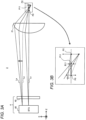
- FIGS. 2A and 2B are diagrams illustrating the overall configuration of the beam coupling device 2.
- FIG. 2A illustrates a side view of the beam coupling device 2 as viewed from the X direction.
- FIG. 2B illustrates a plan view of the beam coupling device 2 as viewed from the Y direction.
- FIG. 2B exemplifies the five LD 31a, 31b, 31c, 31d, and 31e in the LD bar 3.
- the number of LDs 31a to 31e contained in one LD bar 3 is e.g. tens to hundreds.
- the plurality of LDs 31a to 31e in the LD bar 3 are an example of a set of light emitters in the laser light source 30 of the present embodiment.
- the generic term of LDs 31a to 31e may be referred to as "LD 31".
- Each LD 31 constitutes the emitter of the LD bar 3 to emit a light beam to the +Z side.
- FIG. 2A exemplifies a chief ray L1 of the light beam from the outer LD bar 3-1 in the Y direction and a chief ray L2 of the light beam from the central LD bar 3-2.
- FIG. 2B exemplifies a chief ray La of the light beam from the outer LD 31a in the X direction and a chief ray Lc of the light beam from the central LD 31c.
- the central LD 31c in the X and Y directions travels straight through the opposing optical unit 4 and the coupling optical system 20 and has a chief ray Lc parallel to the Z direction.
- the optical unit 4 is configured such that the chief ray L1 of the light beam emitted by the outer LD bars 3-1 of the plurality of LD bars 3 arranged in the Y direction is directed inward, in view of increasing the output of the beam coupling device 2 for spatial beam combining, for example (details will be described later).
- the upper (+Y side) optical unit 4 in the drawing makes the chief ray L1 of the light beam inclined from the Z direction to the lower side (-Y side).
- the beam coupling position P1 in the Y direction where the chief rays L1 and L2 intersect between the LD bars 3 is located on the -Z side from a focal position P0 of the condenser lens 21.
- FIG. 3A exemplifies an optical path before and after the outer chief ray La in the X direction is directed outward.
- an optical image of the surface on the +Z side of the BTU 40 exemplifies an image formation position P2 at which an image is formed by the condenser lens 21.
- the beam diameter per LD 31 is the minimum.
- the beam diameters of the entire light beams of the plurality of LDs 31a to 31e are the minimum at the positions at which the chief rays intersect each other.
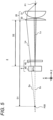
- FIG. 5 is a diagram illustrating a focal length D2 of the cylindrical lens 22.
- the cylindrical lens 22 has a relatively long focal length D2, e.g. equal to or more than the focal length of the condenser lens 21.
- the focal length D2 of the cylindrical lens 22 may be shorter than a distance D1 to the cylindrical lens 22 from the position P20 at the intersection of an extension line Ea of the chief ray La directed outward in the X direction toward the -Z side and an extension line Ec of the central chief ray Lc.
- the extension line Ec corresponds to the optical axis of the condenser lens 21, for example.
- the cylindrical lens 22 is used for the coupling optical system 20 has been described, but the cylindrical lens 22 does not necessarily have to be used.
- various optical systems having a positive refractive power in the X direction larger than a refractive power in the Y direction may be adopted in the coupling optical system 20.
- the beam coupling position P1 in the X and Y directions can be aligned in the same manner as described above.
- FIGS. 6A and 6B illustrate the basic configuration of the optical unit 4.
- the FAC 41 is provided for collimating a light beam on the fast axis Af, and is formed of a cylindrical lens having a positive refractive power, for example.
- the FAC 41 is arranged with the longitudinal direction being the X direction, as illustrated in FIGS. 6A and 6B .
- the light beam from LD 31 is collimated by the FAC 41 in the Y direction (i.e., the fast axis Af) and is incident on the BT 50.
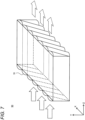
- FIG. 7 illustrates a configuration example of the BT 50.
- the BT 50 is an optical element that rotates a plurality of light beams, respectively, and the BT 50 includes a plurality of oblique lens portions 51.
- the oblique lens portion 51 is a portion of the BT 50 that constitutes a lens for each LD 31, and constitutes e.g. a cylindrical lens.
- the BT 50 is formed so as to arrange a plurality of oblique lens portions 51 at a predetermined pitch in the longitudinal direction, for example.
- the oblique lens portion 51 is inclined by 45° with respect to both the arrangement direction and the thickness direction of the BT 50, for example.
- the pitch of the oblique lens portion 51 is the same as the pitch between the LDs 31 in the LD bar 3, for example.
- the BT 50 rotates the light beam incident from the LD 31 through the FAC 41 by a rotation angle of 90° in the XY plane.
- the slow axis As of the light beam emitted from the BT 50 is oriented in the Y direction
- the fast axis Af is oriented in the X direction.
- the light beam emitted from the BT 50 is divergent light in the Y direction and parallel light in the X direction.
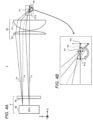
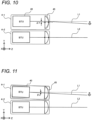
- each optical unit 4 is configured as illustrated in FIG. 8 from the viewpoint of outwardly directing each of the outer chief rays in the X direction, for example.
- the BTU 40 is arranged so as to rotate the longitudinal direction from the X direction by a predetermined rotation angle ⁇ o with the position at which the chief ray of the central LD 31c passes on the XY plane as the rotation axis (e.g., 0.001° ⁇ ⁇ o ⁇ 1°).
- the distance between the chief rays L1 and L2 arriving at the condenser lens 21 from the plurality of optical units 4-1 and 4-2 is smaller than the distance between the optical units 4-1 and 4-2. Therefore, the number of optical units 4 and LD bars 3 to be spatially synthesized by the condenser lens 21 can be increased, and the light output by spatial synthesis can be increased in the beam coupling device 2.
- the beam coupling device 2 includes a laser light source 30 which is an example of the light source, a plurality of optical units 4, and a coupling optical system 20.
- the laser light source 30 includes a plurality of LDs 31 as an example of a plurality of light emitters arranged in the X direction which is an example of the first direction and the Y direction which is an example of a second direction intersecting the first direction.
- the laser light source 30 emits a plurality of light beams having light ray directions intersecting with the X and Y directions from each LD 31.
- the light ray direction of each LD 31 is defined by, for example, the chief ray of each light beam.
- the optical units 4 located outside in the Y direction may be arranged to direct inward orientation for emitting the light beam incident from the light source, for example.
- the directing inward of the outer chief ray L1 in the Y direction can be realized.
- the laser processing machine 1 includes the beam coupling device 2 and the processing head 11 arranged to irradiate a workpiece with a light beam coupled by the beam coupling device 2.
- the plurality of light beams can be coupled at high density by the beam coupling device 2.
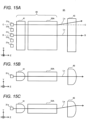
- FIG. 16 illustrates the simulation results of the beam coupling device 2 of the second embodiment.
- the pitch Wo on the +Z side of the BT 50A is made larger by 318 nm than the pitch Wi on the - Z side.
- the pitch between the pitch Wi on the -Z side of the BT 50A and the LD of the LD bar 3 was 0.225000 mm.
- the first and second embodiments are described as an example of the technique disclosed in the present application.
- the technique in the present disclosure is not limited thereto, and can also be applied to embodiments in which changes, substitutions, additions, omissions, and the like are made as appropriate.
- other embodiments will be exemplified.
- the beam coupling device 2 for inwardly directing the outer chief ray L1 in the Y direction has been described.
- the chief ray L1 may not be inwardly directed, and may be outwardly directed, for example. This modification will be described with reference to FIGS. 17A and 17B .
- a beam coupling position can be set at the intersection position P11 between the chief rays La and Lc located on the +Z side from the focal position P0 of the condenser lens 21 as the coupling optical system 20A.
- the beam coupling device P11 in the X and Y directions can be aligned as illustrated in FIGS. 17A and 17B , for example.
- the present disclosure is applicable to various applications in which a plurality of light beams are coupled and used, and is applicable to various laser processing techniques, for example.
Landscapes
- Physics & Mathematics (AREA)
- Optics & Photonics (AREA)
- General Physics & Mathematics (AREA)
- Engineering & Computer Science (AREA)
- Plasma & Fusion (AREA)
- Mechanical Engineering (AREA)
- Condensed Matter Physics & Semiconductors (AREA)
- Electromagnetism (AREA)
- Semiconductor Lasers (AREA)
- Laser Beam Processing (AREA)
- Optical Couplings Of Light Guides (AREA)
Claims (9)
- Dispositif de couplage (2) de faisceaux comprenant :une source de lumière (30) qui comprend une pluralité d'émetteurs de lumière (31) agencés sous la forme d'un ensemble (3) d'émetteurs de lumière (31) dans une première direction (X) et agencés sous la forme d'une pluralité d'ensembles (3) d'émetteurs de lumière (31) dans une seconde direction, destinée à émettre une pluralité de faisceaux lumineux présentant une direction de rayon lumineux (La) à partir de chacun des émetteurs de lumière (31), la première direction (X) et la seconde direction (Y) se croisant l'une l'autre et la direction de rayon lumineux (La) croisant les première et seconde directions ;une pluralité d'unités optiques (4-1 à 4-3) agencées pour guider chaque faisceau lumineux pour chaque ensemble (3) d'émetteurs de lumière (31) agencés dans la première direction (X) dans la source de lumière (30) ; etun système optique de couplage (20) agencé pour coupler la pluralité de faisceaux lumineux guidés par chacune des unités optiques,chacune des unités optiques (4) étant agencée pour diriger vers l'extérieur la direction de rayon lumineux (La) d'un premier faisceau lumineux parmi des faisceaux lumineux émis par l'ensemble (3) d'émetteurs de lumière (31), pour guider les faisceaux lumineux provenant de l'ensemble (3) d'émetteurs de lumière (31) dans le système optique de couplage (20), le premier faisceau lumineux étant émis par un émetteur de lumière qui est situé à l'extérieur dans la première direction (X) pour l'ensemble (3) d'émetteurs de lumière (31).
- Dispositif de couplage (2) de faisceaux selon la revendication 1,le système optique de couplage (20) présentant une réfringence positive dans la première direction (X) supérieure à une réfringence positive dans la seconde direction etla pluralité d'unités optiques (4-1 à 4-3) étant agencées pour diriger vers l'intérieur la direction de rayon lumineux (La) d'un second faisceau lumineux émis par un émetteur de lumière qui est situé à l'extérieur dans de multiples émetteurs de lumière (31) parmi la pluralité d'émetteurs de lumière (31), les multiples émetteurs de lumière (31) étant agencés dans la seconde direction (Y) dans la source de lumière.
- Dispositif de couplage (2) de faisceaux selon la revendication 2, le système optique de couplage (20) comprenant une lentille de condenseur (21) axialement symétrique et une lentille cylindrique (22) présentant une réfringence positive dans la première direction.
- Dispositif de couplage (2) de faisceaux selon la revendication 3, la lentille cylindrique (22) présentant une distance focale plus courte qu'une distance par rapport à la lentille cylindrique (22) à partir d'une position au niveau de laquelle une ligne d'extension (Ec) d'un axe optique de la lentille de condenseur (21) croise une autre ligne d'extension (Ec) obtenue par extension d'un rayon principal (L1) provenant de l'unité optique vers la source de lumière, le rayon principal (L1) correspondant au premier faisceau lumineux dirigé vers l'extérieur par l'unité optique.
- Dispositif de couplage (2) de faisceaux selon l'une quelconque des revendications 2 à 4,chaque unité optique comprenant une lentille de collimateur agencée pour collimater chaque faisceau lumineux provenant de l'ensemble (3) d'émetteurs de lumière (31) dans la seconde direction (Y) etdans la pluralité d'unités optiques (4-1 à 4-3), la lentille de collimateur de l'unité optique située à l'extérieur dans la seconde direction (Y) étant agencée en une position au niveau de laquelle un faisceau lumineux incident est dirigé vers l'intérieur.
- Dispositif de couplage (2) de faisceaux selon l'une quelconque des revendications 2 à 4, dans lequel
parmi la pluralité d'unités optiques (4-1 à 4-3), l'unité optique située à l'extérieur dans la seconde direction (Y) est agencée pour diriger une orientation vers l'intérieur afin d'émettre le faisceau lumineux incident provenant de la source de lumière. - Dispositif de couplage (2) de faisceaux selon l'une quelconque des revendications 1 à 6,l'unité optique comprenant une unité de torsion (50) de faisceaux agencée pour faire tourner chaque faisceau lumineux provenant de l'ensemble (3) d'émetteurs de lumière (31) etl'unité de torsion (50) de faisceau étant agencée à un angle de rotation par rapport à l'ensemble (3) des émetteurs de lumière (31), l'angle de rotation dirigeant vers l'extérieur la direction de rayon lumineux (La) du premier faisceau lumineux émis par l'émetteur de lumière situé à l'extérieur dans la première direction.
- Dispositif de couplage (2) de faisceaux selon l'une quelconque des revendications 1 à 6,l'unité optique comprenant un élément optique présentant une pluralité de parties de lentille correspondant à chaque émetteur de lumière dans l'ensemble (3) d'émetteurs de lumière (31),dans l'élément optique, la pluralité de parties de lentille étant agencées dans la première direction (X) afin d'être inclinées par rapport à la seconde direction etl'élément optique présentant les deux surfaces latérales avec un pas, auquel la pluralité de parties de lentille sont agencées dans une surface à partir de laquelle le faisceau lumineux provenant de l'ensemble (3) d'émetteurs de lumière (31) est émis, supérieur à un pas dans lequel la pluralité de parties de lentille sont agencées dans une autre surface sur laquelle le faisceau lumineux est incident.
- Machine de traitement au laser (1) comprenant :le dispositif de couplage (2) de faisceaux selon l'une quelconque des revendications 1 à 8 ; etune tête de traitement (11) agencée pour soumettre une pièce (15) à un faisceau lumineux couplé par le dispositif de couplage de faisceaux.
Applications Claiming Priority (2)
| Application Number | Priority Date | Filing Date | Title |
|---|---|---|---|
| JP2019215502 | 2019-11-28 | ||
| PCT/JP2020/025874 WO2021106256A1 (fr) | 2019-11-28 | 2020-07-01 | Dispositif de couplage de faisceaux et machine de traitement au laser |
Publications (3)
| Publication Number | Publication Date |
|---|---|
| EP4067978A1 EP4067978A1 (fr) | 2022-10-05 |
| EP4067978A4 EP4067978A4 (fr) | 2023-01-25 |
| EP4067978B1 true EP4067978B1 (fr) | 2025-04-16 |
Family
ID=76130446
Family Applications (1)
| Application Number | Title | Priority Date | Filing Date |
|---|---|---|---|
| EP20892959.6A Active EP4067978B1 (fr) | 2019-11-28 | 2020-07-01 | Dispositif de couplage de faisceaux et machine de traitement au laser |
Country Status (5)
| Country | Link |
|---|---|
| US (1) | US20220271497A1 (fr) |
| EP (1) | EP4067978B1 (fr) |
| JP (1) | JP7462677B2 (fr) |
| CN (1) | CN114746799B (fr) |
| WO (1) | WO2021106256A1 (fr) |
Families Citing this family (1)
| Publication number | Priority date | Publication date | Assignee | Title |
|---|---|---|---|---|
| JP2023020317A (ja) * | 2021-07-30 | 2023-02-09 | パナソニックホールディングス株式会社 | レーザモジュール、レーザ発振器およびレーザ加工システム |
Family Cites Families (21)
| Publication number | Priority date | Publication date | Assignee | Title |
|---|---|---|---|---|
| JPH11156567A (ja) * | 1997-12-02 | 1999-06-15 | Fuji Electric Co Ltd | レーザ印字装置 |
| JP2000019362A (ja) * | 1998-07-07 | 2000-01-21 | Nec Corp | アレイ型半導体レーザ用光結合装置及び該アレイ型半導体レーザを用いた固体レーザ装置 |
| US6773142B2 (en) * | 2002-01-07 | 2004-08-10 | Coherent, Inc. | Apparatus for projecting a line of light from a diode-laser array |
| JP4427280B2 (ja) * | 2002-07-10 | 2010-03-03 | 新日本製鐵株式会社 | 半導体レーザ装置およびそれを用いた固体レーザ装置 |
| US7010194B2 (en) * | 2002-10-07 | 2006-03-07 | Coherent, Inc. | Method and apparatus for coupling radiation from a stack of diode-laser bars into a single-core optical fiber |
| US7881355B2 (en) * | 2005-12-15 | 2011-02-01 | Mind Melters, Inc. | System and method for generating intense laser light from laser diode arrays |
| WO2011109763A2 (fr) * | 2010-03-05 | 2011-09-09 | TeraDiode, Inc. | Système et procédé de combinaison de faisceaux de longueur d'onde par rotation et repositionnement sélectifs |
| US8946594B2 (en) * | 2011-11-04 | 2015-02-03 | Applied Materials, Inc. | Optical design for line generation using microlens array |
| US9746679B2 (en) | 2012-02-22 | 2017-08-29 | TeraDiode, Inc. | Wavelength beam combining laser systems utilizing lens roll for chief ray focusing |
| JP2013214651A (ja) * | 2012-04-03 | 2013-10-17 | Ushio Inc | 半導体レーザ光学装置 |
| DE102013225310B3 (de) * | 2013-12-09 | 2015-05-07 | Trumpf Laser Gmbh | Optikanordnung zur Strahlformung eines Laserstrahls für eine Laserbearbeitungsmaschine |
| WO2015115301A1 (fr) * | 2014-01-30 | 2015-08-06 | 三菱電機株式会社 | Dispositif de couplage de faisceaux et procédé de récupération de sortie pour dispositif de couplage de faisceaux |
| JP6345963B2 (ja) * | 2014-03-28 | 2018-06-20 | 株式会社Screenホールディングス | 光照射装置および描画装置 |
| WO2016187879A1 (fr) * | 2015-05-28 | 2016-12-01 | 温州泛波激光有限公司 | Dispositif de combinaison de faisceaux à réseau laser |
| DE102016100925B4 (de) * | 2016-01-20 | 2018-05-30 | Snaptrack, Inc. | Filterschaltung |
| JP2017135146A (ja) * | 2016-01-25 | 2017-08-03 | 浜松ホトニクス株式会社 | レーザヘッド、及び、レーザ装置 |
| US10571708B2 (en) * | 2016-02-09 | 2020-02-25 | Mitsubishi Electric Corporation | Beam shaping device and laser oscillator |
| EP3506437A4 (fr) * | 2016-08-26 | 2019-11-27 | Panasonic Intellectual Property Management Co., Ltd. | Module laser |
| CN110383607B (zh) * | 2017-03-09 | 2021-03-02 | 三菱电机株式会社 | 波长耦合激光器装置 |
| WO2019163335A1 (fr) * | 2018-02-26 | 2019-08-29 | パナソニックIpマネジメント株式会社 | Résonateur optique et machine de traitement laser |
| JP7165337B2 (ja) * | 2018-08-23 | 2022-11-04 | 株式会社島津製作所 | 光結合装置 |
-
2020
- 2020-07-01 EP EP20892959.6A patent/EP4067978B1/fr active Active
- 2020-07-01 WO PCT/JP2020/025874 patent/WO2021106256A1/fr not_active Ceased
- 2020-07-01 JP JP2021561150A patent/JP7462677B2/ja active Active
- 2020-07-01 CN CN202080081706.9A patent/CN114746799B/zh active Active
-
2022
- 2022-05-12 US US17/742,652 patent/US20220271497A1/en active Pending
Also Published As
| Publication number | Publication date |
|---|---|
| CN114746799A (zh) | 2022-07-12 |
| CN114746799B (zh) | 2025-08-22 |
| JP7462677B2 (ja) | 2024-04-05 |
| JPWO2021106256A1 (fr) | 2021-06-03 |
| WO2021106256A1 (fr) | 2021-06-03 |
| US20220271497A1 (en) | 2022-08-25 |
| EP4067978A1 (fr) | 2022-10-05 |
| EP4067978A4 (fr) | 2023-01-25 |
Similar Documents
| Publication | Publication Date | Title |
|---|---|---|
| US11353715B2 (en) | Wavelength beam combining laser systems utilizing lens roll for chief ray focusing | |
| JP6412478B2 (ja) | 波長合成レーザシステム | |
| US20200355931A1 (en) | Wavelength beam combining laser systems with micro-optics | |
| US11287574B2 (en) | Optical fiber bundle with beam overlapping mechanism | |
| US11914166B2 (en) | Systems and methods for alignment of wavelength beam combining resonators | |
| EP4067978B1 (fr) | Dispositif de couplage de faisceaux et machine de traitement au laser | |
| WO2021177001A1 (fr) | Dispositif laser à semi-conducteur | |
| EP4067947B1 (fr) | Unité optique, dispositif de couplage de faisceau, et machine de traitement au laser | |
| CN111799655A (zh) | 高功率半导体激光器 | |
| US20240045221A1 (en) | Optical module with double emitter chips and double dove prisms | |
| US20250105592A1 (en) | Laser apparatus and laser processing machine | |
| US20040136666A1 (en) | Fiber delivery system for laser diodes | |
| US20240176156A1 (en) | Optical system and laser device, collimator lens | |
| WO2015191451A1 (fr) | Systèmes laser combinant des faisceaux de longueur d'onde utilisant un rouleau de lentille de focalisation pour rayon principal |
Legal Events
| Date | Code | Title | Description |
|---|---|---|---|
| STAA | Information on the status of an ep patent application or granted ep patent |
Free format text: STATUS: THE INTERNATIONAL PUBLICATION HAS BEEN MADE |
|
| PUAI | Public reference made under article 153(3) epc to a published international application that has entered the european phase |
Free format text: ORIGINAL CODE: 0009012 |
|
| STAA | Information on the status of an ep patent application or granted ep patent |
Free format text: STATUS: REQUEST FOR EXAMINATION WAS MADE |
|
| 17P | Request for examination filed |
Effective date: 20220518 |
|
| AK | Designated contracting states |
Kind code of ref document: A1 Designated state(s): AL AT BE BG CH CY CZ DE DK EE ES FI FR GB GR HR HU IE IS IT LI LT LU LV MC MK MT NL NO PL PT RO RS SE SI SK SM TR |
|
| A4 | Supplementary search report drawn up and despatched |
Effective date: 20230103 |
|
| RIC1 | Information provided on ipc code assigned before grant |
Ipc: G02B 27/09 20060101ALI20221221BHEP Ipc: G02B 6/42 20060101ALI20221221BHEP Ipc: B23K 26/064 20140101ALI20221221BHEP Ipc: G02B 27/12 20060101AFI20221221BHEP |
|
| DAV | Request for validation of the european patent (deleted) | ||
| DAX | Request for extension of the european patent (deleted) | ||
| GRAP | Despatch of communication of intention to grant a patent |
Free format text: ORIGINAL CODE: EPIDOSNIGR1 |
|
| STAA | Information on the status of an ep patent application or granted ep patent |
Free format text: STATUS: GRANT OF PATENT IS INTENDED |
|
| INTG | Intention to grant announced |
Effective date: 20241114 |
|
| GRAS | Grant fee paid |
Free format text: ORIGINAL CODE: EPIDOSNIGR3 |
|
| GRAA | (expected) grant |
Free format text: ORIGINAL CODE: 0009210 |
|
| STAA | Information on the status of an ep patent application or granted ep patent |
Free format text: STATUS: THE PATENT HAS BEEN GRANTED |
|
| AK | Designated contracting states |
Kind code of ref document: B1 Designated state(s): AL AT BE BG CH CY CZ DE DK EE ES FI FR GB GR HR HU IE IS IT LI LT LU LV MC MK MT NL NO PL PT RO RS SE SI SK SM TR |
|
| REG | Reference to a national code |
Ref country code: GB Ref legal event code: FG4D |
|
| REG | Reference to a national code |
Ref country code: CH Ref legal event code: EP |
|
| REG | Reference to a national code |
Ref country code: IE Ref legal event code: FG4D |
|
| REG | Reference to a national code |
Ref country code: DE Ref legal event code: R096 Ref document number: 602020049726 Country of ref document: DE |
|
| REG | Reference to a national code |
Ref country code: NL Ref legal event code: MP Effective date: 20250416 |
|
| PG25 | Lapsed in a contracting state [announced via postgrant information from national office to epo] |
Ref country code: NL Free format text: LAPSE BECAUSE OF FAILURE TO SUBMIT A TRANSLATION OF THE DESCRIPTION OR TO PAY THE FEE WITHIN THE PRESCRIBED TIME-LIMIT Effective date: 20250416 |
|
| REG | Reference to a national code |
Ref country code: AT Ref legal event code: MK05 Ref document number: 1786119 Country of ref document: AT Kind code of ref document: T Effective date: 20250416 |
|
| PG25 | Lapsed in a contracting state [announced via postgrant information from national office to epo] |
Ref country code: FI Free format text: LAPSE BECAUSE OF FAILURE TO SUBMIT A TRANSLATION OF THE DESCRIPTION OR TO PAY THE FEE WITHIN THE PRESCRIBED TIME-LIMIT Effective date: 20250416 Ref country code: PT Free format text: LAPSE BECAUSE OF FAILURE TO SUBMIT A TRANSLATION OF THE DESCRIPTION OR TO PAY THE FEE WITHIN THE PRESCRIBED TIME-LIMIT Effective date: 20250818 Ref country code: ES Free format text: LAPSE BECAUSE OF FAILURE TO SUBMIT A TRANSLATION OF THE DESCRIPTION OR TO PAY THE FEE WITHIN THE PRESCRIBED TIME-LIMIT Effective date: 20250416 |
|
| PGFP | Annual fee paid to national office [announced via postgrant information from national office to epo] |
Ref country code: DE Payment date: 20250722 Year of fee payment: 6 |
|
| REG | Reference to a national code |
Ref country code: LT Ref legal event code: MG9D |
|
| PG25 | Lapsed in a contracting state [announced via postgrant information from national office to epo] |
Ref country code: NO Free format text: LAPSE BECAUSE OF FAILURE TO SUBMIT A TRANSLATION OF THE DESCRIPTION OR TO PAY THE FEE WITHIN THE PRESCRIBED TIME-LIMIT Effective date: 20250716 Ref country code: GR Free format text: LAPSE BECAUSE OF FAILURE TO SUBMIT A TRANSLATION OF THE DESCRIPTION OR TO PAY THE FEE WITHIN THE PRESCRIBED TIME-LIMIT Effective date: 20250717 |
|
| PG25 | Lapsed in a contracting state [announced via postgrant information from national office to epo] |
Ref country code: PL Free format text: LAPSE BECAUSE OF FAILURE TO SUBMIT A TRANSLATION OF THE DESCRIPTION OR TO PAY THE FEE WITHIN THE PRESCRIBED TIME-LIMIT Effective date: 20250416 |
|
| PG25 | Lapsed in a contracting state [announced via postgrant information from national office to epo] |
Ref country code: BG Free format text: LAPSE BECAUSE OF FAILURE TO SUBMIT A TRANSLATION OF THE DESCRIPTION OR TO PAY THE FEE WITHIN THE PRESCRIBED TIME-LIMIT Effective date: 20250416 |
|
| PG25 | Lapsed in a contracting state [announced via postgrant information from national office to epo] |
Ref country code: HR Free format text: LAPSE BECAUSE OF FAILURE TO SUBMIT A TRANSLATION OF THE DESCRIPTION OR TO PAY THE FEE WITHIN THE PRESCRIBED TIME-LIMIT Effective date: 20250416 |
|
| PG25 | Lapsed in a contracting state [announced via postgrant information from national office to epo] |
Ref country code: AT Free format text: LAPSE BECAUSE OF FAILURE TO SUBMIT A TRANSLATION OF THE DESCRIPTION OR TO PAY THE FEE WITHIN THE PRESCRIBED TIME-LIMIT Effective date: 20250416 |
|
| PG25 | Lapsed in a contracting state [announced via postgrant information from national office to epo] |
Ref country code: RS Free format text: LAPSE BECAUSE OF FAILURE TO SUBMIT A TRANSLATION OF THE DESCRIPTION OR TO PAY THE FEE WITHIN THE PRESCRIBED TIME-LIMIT Effective date: 20250716 |
|
| PG25 | Lapsed in a contracting state [announced via postgrant information from national office to epo] |
Ref country code: IS Free format text: LAPSE BECAUSE OF FAILURE TO SUBMIT A TRANSLATION OF THE DESCRIPTION OR TO PAY THE FEE WITHIN THE PRESCRIBED TIME-LIMIT Effective date: 20250816 |
|
| PG25 | Lapsed in a contracting state [announced via postgrant information from national office to epo] |
Ref country code: LV Free format text: LAPSE BECAUSE OF FAILURE TO SUBMIT A TRANSLATION OF THE DESCRIPTION OR TO PAY THE FEE WITHIN THE PRESCRIBED TIME-LIMIT Effective date: 20250416 |
|
| PG25 | Lapsed in a contracting state [announced via postgrant information from national office to epo] |
Ref country code: SM Free format text: LAPSE BECAUSE OF FAILURE TO SUBMIT A TRANSLATION OF THE DESCRIPTION OR TO PAY THE FEE WITHIN THE PRESCRIBED TIME-LIMIT Effective date: 20250416 Ref country code: DK Free format text: LAPSE BECAUSE OF FAILURE TO SUBMIT A TRANSLATION OF THE DESCRIPTION OR TO PAY THE FEE WITHIN THE PRESCRIBED TIME-LIMIT Effective date: 20250416 |
|
| REG | Reference to a national code |
Ref country code: DE Ref legal event code: R097 Ref document number: 602020049726 Country of ref document: DE |
|
| PG25 | Lapsed in a contracting state [announced via postgrant information from national office to epo] |
Ref country code: CZ Free format text: LAPSE BECAUSE OF FAILURE TO SUBMIT A TRANSLATION OF THE DESCRIPTION OR TO PAY THE FEE WITHIN THE PRESCRIBED TIME-LIMIT Effective date: 20250416 |
|
| PG25 | Lapsed in a contracting state [announced via postgrant information from national office to epo] |
Ref country code: EE Free format text: LAPSE BECAUSE OF FAILURE TO SUBMIT A TRANSLATION OF THE DESCRIPTION OR TO PAY THE FEE WITHIN THE PRESCRIBED TIME-LIMIT Effective date: 20250416 |
|
| PG25 | Lapsed in a contracting state [announced via postgrant information from national office to epo] |
Ref country code: SK Free format text: LAPSE BECAUSE OF FAILURE TO SUBMIT A TRANSLATION OF THE DESCRIPTION OR TO PAY THE FEE WITHIN THE PRESCRIBED TIME-LIMIT Effective date: 20250416 |
|
| PG25 | Lapsed in a contracting state [announced via postgrant information from national office to epo] |
Ref country code: IT Free format text: LAPSE BECAUSE OF FAILURE TO SUBMIT A TRANSLATION OF THE DESCRIPTION OR TO PAY THE FEE WITHIN THE PRESCRIBED TIME-LIMIT Effective date: 20250416 |
|
| PG25 | Lapsed in a contracting state [announced via postgrant information from national office to epo] |
Ref country code: RO Free format text: LAPSE BECAUSE OF FAILURE TO SUBMIT A TRANSLATION OF THE DESCRIPTION OR TO PAY THE FEE WITHIN THE PRESCRIBED TIME-LIMIT Effective date: 20250416 |
|
| PLBE | No opposition filed within time limit |
Free format text: ORIGINAL CODE: 0009261 |
|
| STAA | Information on the status of an ep patent application or granted ep patent |
Free format text: STATUS: NO OPPOSITION FILED WITHIN TIME LIMIT |
|
| REG | Reference to a national code |
Ref country code: CH Ref legal event code: H13 Free format text: ST27 STATUS EVENT CODE: U-0-0-H10-H13 (AS PROVIDED BY THE NATIONAL OFFICE) Effective date: 20260224 |
|
| REG | Reference to a national code |
Ref country code: CH Ref legal event code: L10 Free format text: ST27 STATUS EVENT CODE: U-0-0-L10-L00 (AS PROVIDED BY THE NATIONAL OFFICE) Effective date: 20260225 |
|
| PG25 | Lapsed in a contracting state [announced via postgrant information from national office to epo] |
Ref country code: LU Free format text: LAPSE BECAUSE OF NON-PAYMENT OF DUE FEES Effective date: 20250701 |
|
| 26N | No opposition filed |
Effective date: 20260119 |
|
| GBPC | Gb: european patent ceased through non-payment of renewal fee |
Effective date: 20250716 |
|
| REG | Reference to a national code |
Ref country code: BE Ref legal event code: MM Effective date: 20250731 |
|
| PG25 | Lapsed in a contracting state [announced via postgrant information from national office to epo] |
Ref country code: GB Free format text: LAPSE BECAUSE OF NON-PAYMENT OF DUE FEES Effective date: 20250716 |
|
| PG25 | Lapsed in a contracting state [announced via postgrant information from national office to epo] |
Ref country code: BE Free format text: LAPSE BECAUSE OF NON-PAYMENT OF DUE FEES Effective date: 20250731 |
|
| PG25 | Lapsed in a contracting state [announced via postgrant information from national office to epo] |
Ref country code: FR Free format text: LAPSE BECAUSE OF NON-PAYMENT OF DUE FEES Effective date: 20250731 |
|
| PG25 | Lapsed in a contracting state [announced via postgrant information from national office to epo] |
Ref country code: CH Free format text: LAPSE BECAUSE OF NON-PAYMENT OF DUE FEES Effective date: 20250731 |