EP4068324B1 - Schaltgerät mit verriegelbarer frontabdeckung - Google Patents
Schaltgerät mit verriegelbarer frontabdeckung Download PDFInfo
- Publication number
- EP4068324B1 EP4068324B1 EP21166318.2A EP21166318A EP4068324B1 EP 4068324 B1 EP4068324 B1 EP 4068324B1 EP 21166318 A EP21166318 A EP 21166318A EP 4068324 B1 EP4068324 B1 EP 4068324B1
- Authority
- EP
- European Patent Office
- Prior art keywords
- switching device
- front cover
- switching
- locking means
- slide
- Prior art date
- Legal status (The legal status is an assumption and is not a legal conclusion. Google has not performed a legal analysis and makes no representation as to the accuracy of the status listed.)
- Active
Links
Images

Classifications
-
- H—ELECTRICITY
- H01—ELECTRIC ELEMENTS
- H01H—ELECTRIC SWITCHES; RELAYS; SELECTORS; EMERGENCY PROTECTIVE DEVICES
- H01H9/00—Details of switching devices, not covered by groups H01H1/00 - H01H7/00
- H01H9/10—Adaptation for built-in fuses
- H01H9/104—Adaptation for built-in fuses with interlocking mechanism between switch and fuse
-
- H—ELECTRICITY
- H01—ELECTRIC ELEMENTS
- H01H—ELECTRIC SWITCHES; RELAYS; SELECTORS; EMERGENCY PROTECTIVE DEVICES
- H01H85/00—Protective devices in which the current flows through a part of fusible material and this current is interrupted by displacement of the fusible material when this current becomes excessive
- H01H85/02—Details
- H01H85/25—Safety arrangements preventing or inhibiting contact with live parts, including operation of isolation on removal of cover
-
- H—ELECTRICITY
- H01—ELECTRIC ELEMENTS
- H01H—ELECTRIC SWITCHES; RELAYS; SELECTORS; EMERGENCY PROTECTIVE DEVICES
- H01H9/00—Details of switching devices, not covered by groups H01H1/00 - H01H7/00
- H01H9/20—Interlocking, locking, or latching mechanisms
- H01H9/22—Interlocking, locking, or latching mechanisms for interlocking between casing, cover, or protective shutter and mechanism for operating contacts
- H01H9/226—Interlocking, locking, or latching mechanisms for interlocking between casing, cover, or protective shutter and mechanism for operating contacts the casing containing electrical equipment other than and operated by the switch
-
- H—ELECTRICITY
- H01—ELECTRIC ELEMENTS
- H01H—ELECTRIC SWITCHES; RELAYS; SELECTORS; EMERGENCY PROTECTIVE DEVICES
- H01H9/00—Details of switching devices, not covered by groups H01H1/00 - H01H7/00
- H01H9/16—Indicators for switching condition, e.g. "on" or "off"
Definitions
- the present invention relates to a switching device.
- the invention relates to a multi-pole switching device for use on busbar systems.
- Busbar systems are widespread and allow switching devices to be mounted directly on the busbar during installation.
- the dimensioning of the busbars of the busbar system depends primarily on the current load. In switchgear, several busbars can be laid in parallel.
- the busbars are usually made of aluminum or copper and are generally uninsulated, which simplifies the installation of connection and switching elements.
- Switching devices in particular electrical load switches, especially those with fuses, are used, for example, in the industrial and power plant sectors both as busbar feed-in switches and as outgoing switches for switching highly inductive loads (e.g. motors), including overloads.
- highly inductive loads e.g. motors
- the switching device according to the invention is, in particular, a switching device for use on a busbar system, wherein the switching device covers a current range in which cylindrical fuses are used, for example D0 fuses.
- the switching device according to the invention can be used, for example, as a backup fuse for DIN rail-mounted devices, as Protective device for drives in production facilities and/or in photovoltaic installations.
- a switching device designed for use on busbar systems is, for example, from the EP 1 246 212 A2 Furthermore, the EP 1 271 583 A2 and the EP 2 747 104 B1 Switchgear designed for use on busbar systems.
- the GB 1 439 681 A discloses a switching device having the features of the preamble of claim 1.
- the EP 3 211 650 A1 and the DE 10 2012 025 602 A1 reveal further state of the art.
- the object of the invention is to develop a switching device having the features of the preamble of patent claim 1 in such a way that a high level of operating safety is ensured.
- the switching device comprises a housing and at least one switching contact, wherein the switching device has a fuse holder associated with the respective switching contact.
- the fuse holder is designed, in particular, to accommodate a cylindrical fuse, in particular a D0 fuse.
- the switching device is designed, in particular, as a load-break switch for a busbar system.
- the switching device has a front cover mounted in the housing for covering the at least one fuse holder in a closed position of the front cover.
- the fuse holders of the switching device or the fuses mounted therein are not accessible to the operator, so that reaching into the area of the fuse holder or a fuse mounted therein is not possible when the front cover is closed.
- the at least one switching contact is displaceable via a
- the slider can be moved from a contact position to an interruption position and vice versa.
- the slider is preferably mounted in the housing so that it can be moved linearly. Such a slider is also referred to as an actuating slider.
- the slider is provided with a locking means or a locking means interacts with the slider, in particular the locking means is displaceable together with the slider. In the contact position of the switching contact, the locking means locks the front cover when the front cover is in the closed position.
- the locking means prevents the front cover from being opened.
- the front cover cannot therefore be opened when the switching device is in the switched-on state. This prevents the operator from opening the switching device when it is switched on, for example to replace a fuse, and thus exposing themselves to the risk of coming into contact with a live component. Accordingly, the design according to the invention ensures that the front cover can only be opened when the switching contact is in an interrupted position, meaning the switching device is in the switched-off state.
- the locking means is part of the slide or can be moved together with the slide, the locking of the front cover is directly connected to the slide, thus the component of the switching device that directly influences the switching position of the switching contact.
- the switching device has a manually operable actuating lever, whereby this actuating lever acts on the slide.
- Such actuating levers are typically designed in such a way that the actuating lever has a certain amount of freewheeling in order to ensure sudden switching of the switching contact, for example with the aid of an intermediate snap-action switching mechanism.
- the disadvantage here is that the actuating lever can be moved over a certain range without the slide moving.
- locking means that are directly connected to the operating lever is to be regarded as disadvantageous, since a movement of the operating lever which does not yet lead to a switching of the switching contact could nevertheless lead to a locking means which interacts with the operating lever no longer locking the cover, so that this locking does not reliably prevent the front cover from opening even when the switching contact is in the contact position and the operating lever is in the corresponding position.
- the formation of the locking means in the slide or the connection of the locking means to the slide has the advantage that the locking means can be arranged inside the housing of the switching device, so that unintentional damage to the locking means can be avoided.
- the front cover is pivotably mounted in the housing.
- one contact element of the switching contact is mounted in the slide and another contact element of the switching contact is mounted, preferably stationary, in the housing.
- the locking means has a locking structure, wherein the locking structure in the contact position engages behind a counter structure of the front cover when the front cover is in the closed position, in particular engages behind the counter structure on a side facing the front side.
- this counter structure penetrates the housing in the closed position of the front cover, insofar as it protrudes into the interior of the housing.
- the locking means in particular the locking structure, has a display surface for displaying the switching state of the at least one switching contact, wherein the housing or the front cover has a viewing window, wherein, when the front cover is closed, at least a portion of the display surface is visible through the viewing window.
- the viewing window is designed such that only a portion of the display surface is visible.
- the display surface is designed such that the display surface has a symbol indicating the contact position, thus the on position of the switching device, and a symbol indicating the interruption position, thus the off position of the switching device.
- the slide is preferably mounted entirely within the housing and, in particular, in an area of the switching device adjacent to a rear wall of the housing. This places the slide particularly close to the busbars of the busbar system.
- the locking means is essentially rod-shaped and extends from the slider in the direction of the front cover.
- the locking means protrudes from the front of the housing, in particular if it is arranged inside the front cover when the front cover is closed.
- the locking structure is plate-shaped.
- the locking structure forms a free end of the locking means.
- the front cover has a counter structure with a recess or a through opening, wherein the locking structure is arranged within the recess or the through opening in the contact position when the front cover is closed.
- the front cover is preferably designed as a cover hood so that the fuse holders or the fuses arranged in the fuse holders partially protrude from the housing of the switching device and are still covered at the front and sides by the cover. This makes the fuses and fuse holders particularly easy to access when the front cover is open, simplifying the replacement, removal, and/or insertion of fuses.
- the switching device has a locking means, wherein the locking means can be moved against a restoring force of a restoring means from a locked position, in which the locking means prevents displacement of the slide, to an open position, in which the locking means allows displacement of the slide. In the locked position, the slide cannot therefore be moved from the interruption position to the contact position, thereby preventing the switching device from being switched on.
- the front cover has a holding structure, wherein this holding structure holds the locking means in the open position when the front cover is in the closed position.
- the front cover acts on the locking means with the holding structure in such a way that the locking means is in the open position, so that the switching device can be switched on.
- the retaining structure of the front cover no longer acts on the locking means, so that the locking means is moved from the open position to the locked position due to the return means and in this way prevents the switching device from being switched on by blocking the movement of the slide.
- the locking means is mounted in the housing so as to be linearly displaceable, in particular mounted in the housing so as to be displaceable perpendicular to the direction of displacement of the slide.
- the holding structure of the front cover which cooperates with the locking means, penetrates the housing in the closed position of the front cover, insofar as it projects into the housing of the switching device.
- the locking means is mounted within the housing, whereby an unintentional displacement of the locking means when the cover is open is prevented or at least made more difficult.
- the holding structure cooperating with the locking means passes through a preferably slot-shaped through-opening in the housing, said through-opening being designed to be finger-safe.
- the switching device has a stop on the housing side, with the locking means resting against this stop in the locking position.
- the return means is an integral part of the locking means and the locking means is preferably formed in one piece.
- the return means is preferably rod-shaped and is supported at a free end facing away from the remaining locking means on a housing-side structure of the switching device.
- the blocking means preferably has a blocking structure and the slider has a counter-structure cooperating with the blocking structure, wherein in the blocking position of the blocking means the blocking structure is located in the displacement path of the counter-structure of the slider and in the open position the blocking structure is located outside the displacement path of the counter-structure of the slider.
- the blocking structure is formed at the end of the blocking means.
- the locking means is an integral part of the slide, insofar as the locking means forms a part of the slide.
- the locking means is a separate component, wherein the locking means is connected to the Slider is connected, in particular, is connected to the slider in a locking manner.
- the locking means can be manufactured independently of the slider, in particular the display surface to be applied to the locking means.
- the locking means can be made of a different material than the slider. This allows the respective materials of the locking means and the slider to be adapted separately to the respective requirements.
- the switching device has an actuatable switching mechanism for transferring the at least one switching contact from the contact position to the interruption position and vice versa, wherein the switching mechanism has a joint arrangement that interacts with the slide, preferably a toggle joint arrangement.
- the actuatable switching mechanism is preferably designed as a snap-action switching mechanism.
- the locking means and the blocking means are each arranged in the area between two fuse receptacles, preferably with the blocking means arranged between the locking means and a pivot axis of the front cover.
- This design enables particularly optimal utilization of the available installation space in the longitudinal, transverse, and vertical directions of the switching device.
- the switching device is designed as a switching device for a busbar system, in particular as a load-break switch for a busbar system, wherein the switching device has a number of fuse receptacles corresponding to the number of busbars and a switching contact assigned to the respective fuse receptacle, wherein the fuse receptacles are arranged along a longitudinal direction of the switching device, preferably transversely to the busbars.
- the switching device has three fuse holders.
- the locking means and/or the blocking means are made in particular of plastic.
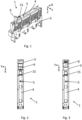
- the Fig. 1 to 14 show a first embodiment of the switching device 1 according to the invention or subcomponents of the first embodiment of the switching device 1 according to the invention.
- the switching device 1 is designed here as a multi-pole switching device 1 for use on a busbar system with three busbars.
- the switching device 1 has a rear side 24 facing the busbars and a front side 23 facing away from the busbars.
- the switching device 1 according to the invention has three fuse receptacles 14 arranged in a row transversely to the busbar system, wherein the respective fuse receptacle 14 is designed to accommodate a cylindrical fuse, in this case a DO2 fuse.
- a switching contact 2 is assigned to the respective fuse receptacle 14 of the switching device 1, wherein the switching contacts 2 are in turn arranged in a row along a longitudinal direction X of the switching device 1.
- the switching device 1 has a front cover 4 pivotally connected to a housing 3 of the switching device 1, wherein the front cover 4 is designed here as a cover hood. In a closed position of the front cover 4, thus closed front cover 4, the front cover 4 covers the fuse holders 14 on the front side.
- the three switching contacts 2 are connected via a longitudinally directed X of the switching device 1
- a slider 10, which is mounted in the housing 3 and is linearly displaceable, can be moved from a contact position to an interruption position and vice versa.
- one contact element 21 of the respective switching contact 2 is mounted in the slider 10, and another contact element 22 of the respective switching contact 2 is mounted in a stationary manner in the housing 3.
- the other contact elements 22 of the respective switching contact 2 are designed to contact one of the three busbars when the switching device 1 is connected to the busbar system, thus forming busbar contacts.
- One of the contact elements 21 is designed as bridge contacts, with the respective bridge contact, in the contact position, contacting both the busbar contact and an input current conductor 25 assigned to the respective fuse holder 14.
- the switching device 1 has a manually operable actuating lever 6, wherein this actuating lever 6 interacts with a snap-action switching mechanism 20, which in turn interacts with the slide 10.
- the slide 10 forms, with further joints, a toggle joint arrangement, wherein this toggle joint arrangement is in an over-center position when the switching device 1 is switched on, thus in a state in which the switching contacts 2 are in the contact position.
- the Fig. 1, 2 , 6 to 10 show the switching device 1 according to the invention in a switched-off state, thus with the switching contacts 2 in the interruption position.
- the electrical fuses or the fuse holders 14 are de-energized, in particular the respective input current conductor 25 of the fuse holder 14 is de-energized.
- the Fig. 3 , 4 and 5 The switching device 1 is in a switched-on state, thus in a state with the switching contacts 2 in the contact position. In this state, the fuses or the input current conductors 25 are live.
- the switching device 1 is designed in such a way that the front cover 4 can only be opened when the switching device 1 is switched off.
- the switching device 1 has a locking means 7 which is connected to the slide 10 and is accordingly displaceable together with the slider 10, wherein the locking means 7 locks the front cover 4 in the contact position of the switching contacts 2 when the front cover 4 is in the closed position.
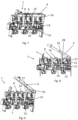
- Fig. 4 and 5 in which the front cover 4 is shown partially in section and the area in which the locking means 7 interacts with the front cover 4 is shown.
- the locking means 7 has a plate-shaped locking structure 8, wherein the locking structure 8, in the contact position when the front cover 4 is in the closed position, engages behind a counter structure 9 of the front cover 4 on a side of the counter structure 9 that faces the front side 23.
- the counter structure 9 is formed in the present case in a connecting web of the front cover 4 running in the transverse direction Y, as in particular the Fig. 10 can be seen.
- the counter structure 9 has a through opening, wherein the locking structure 8 is retracted into this through opening in the contact position and thus prevents the front cover 4 from pivoting out of the closed position.
- the locking structure 8 is no longer in engagement with the counter structure 9 when the front cover 4 is closed.
- This state is, for example, in the Fig. 6 In this state, i.e., in the off position of the switching device 1, the front cover 4 can be pivoted and thus opened, for example, to replace a fuse.
- the front cover 4 has a handle 15.
- the locking means 7 is designed in such a way that it protrudes on the front side 23 of the switching device 1 relative to the housing 3 of the switching device 1.
- the switching position of the switching device 1 can be seen from the front side 23 of the switching device 1, thus on a side of the switching device 1 facing the operator.
- This switching position indication is implemented in the present case by the Locking structure 8 has a display surface 18 for displaying the switching state of the switching contacts 2, wherein the front cover 4 has a viewing window 5, wherein when the front cover 4 is closed, only a partial area, in this case approximately half of the entire display surface 18, is visible through the window 5.
- the display surface 18 has a first symbol "I” for displaying the switched-on state and a second symbol “0" for displaying the switched-off state, wherein the dimensions and arrangement of the viewing window 5 are such that in the respective switching position, only the corresponding symbol is visible through the viewing window 5.
- the switching device 1 has a locking means 11 which is mounted so as to be displaceable perpendicular to the direction of displacement of the slide 10 and which, in the present case, is linearly displaceable in the vertical direction Z of the switching device.
- the locking means 11 can be transferred from a locked position to an open position against a restoring force of a restoring means 17, which in the present case is an integral part of the locking means 11.
- the locked position which, for example, Fig. 8
- the locking means 11 rests with its end facing away from the slide 10 against a housing-side stop of the switching device 1.
- the locking means 11 is displaced in this position maximally in the direction of the front side 23.
- the locking means 11 has a locking structure 12 and the slide 10 has a counter structure 13, wherein in the locked position of the locking means 11, the locking structure 12 is located in the displacement path of the counter structure 13, so that in the locked position the locking structure 12 forms a stop for the counter structure 13 and in this way prevents a displacement of the slide 10 from the interruption position into the contact position and thus an actuation of the switching contacts 2.
- the front cover 4 is closed, as is the case, for example, in the Fig. 6
- the locking means 11 is displaced in the direction of the slide 10, so that the locking structure 12 is arranged below the counter structure 13 and thus outside the displacement path of the counter structure 13.
- a displacement of the slide 10 and thus a switching of the switching device 1 is possible.
- the front cover 4 has a locking device 11 which interacts with the
- Holding structure 16 wherein this holding structure 16 holds the locking means 11 in the open position when the front cover 4 is in the closed position.
- the holding structure 16 is fin-shaped in the present case and, when the front cover 4 is in the closed position, passes through a through slot 28 in a front wall 27 of the housing 3 and rests against the locking means 11 at the end. After opening the front cover 4, which, as already explained, is only possible when the switching device 1 is in the off position, the holding structure 16 no longer acts on the locking means 11, so that the locking means 11 is transferred from the open position to the locked position due to the restoring force of the restoring means 17, so that switching of the switching device 1 is not possible when the front cover 4 is open.
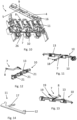
- the design of the locking means 11 is shown in the Fig. 14 shown in more detail.
- the locking structure 12 is designed as a pin protruding in the transverse direction Y of the switching device 1.
- the return means 17 of the locking means 11 is rod-shaped. A free end of the return means 17 is supported on a structure on the housing.
- the locking means 7 and the blocking means 11 are each arranged in the area between two of the securing receptacles 14, wherein the blocking means 11 is arranged in the present case between the locking means 7 and the pivot axis of the front cover 4.
- the locking means 7 is designed as a separate component, such as in particular the Fig. 12 can be seen.
- the locking means 7 is connected to the slide 10 in a locking manner, wherein the locking means 7 and the slide 10 have locking means 19 which interact with one another for this purpose.
- the locking means 19 of the locking means 7 are formed in the present case by two elastically deformable, parallel webs, wherein during the process of connecting the locking means 7 to the slide 10, the two webs are bent apart under the action of the slide-side locking means 19 and come to rest behind the slide-side locking means 19 upon further displacement, in this case by further pivoting of the locking means 7. This realizes the locking connection or a clip connection between the slide 10 and the locking means 7.
- the locking means 7 is arranged in a receiving structure of the slider 10, wherein the receiving structure of the slider 10 is designed such that the locking means 7 is first inserted into this receptacle and can be pivoted in this receptacle in order to enable pivoting of the locking means 7 for the purpose of locking the locking means 19.
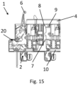
- the Fig. 15 shows a further embodiment of the switching device 1 according to the invention, wherein this embodiment differs from the first embodiment essentially in the design of the locking means 7, in particular the locking structure 8, and the counter structure 9.
- the counter structure 9 associated with the front cover 4 projects into the housing interior of the switching device 1 and the locking structure 8 is formed within the housing 3 of the switching device 1.
Landscapes
- Switch Cases, Indication, And Locking (AREA)
Description
- Die vorliegende Erfindung betrifft ein Schaltgerät. Die Erfindung betrifft insbesondere ein mehrpoliges Schaltgerät für den Einsatz auf Sammelschienensystemen. Sammelschienensysteme sind weit verbreitet und ermöglichen es, Schaltgeräte bei deren Installation direkt auf die Schiene zu montieren. Die Dimensionierung der Stromschienen des Sammelschienensystems ist in erster Linie von der Strombelastung abhängig. In Schaltanlagen können mehrere Sammelschienen parallel verlegt werden. Die Sammelschienen werden in der Regel aus Aluminium oder Kupfer gefertigt und sind in der Regel unisoliert, wodurch die Montage von Anschluss- und Schaltelementen vereinfacht wird.
- Schaltgeräte, insbesondere elektrische Lastschalter, insbesondere solche mit Sicherungen, finden beispielsweise im Industrie- und Kraftwerksbereich sowohl als Sammelschienen-Einspeiseschalter als auch als Abgangsschalter für das Schalten von hochinduktiven Lasten (z. B. Motoren) einschließlich Überlast Verwendung.
- Bei dem erfindungsgemäßen Schaltgerät handelt es sich insbesondere um ein Schaltgerät für die Verwendung auf einem Sammelschienensystem, wobei das Schaltgerät einen Strombereich abdeckt, in dem zylindrische Sicherungen zum Einsatz kommen, beispielsweise D0-Sicherungen. Das erfindungsgemäße Schaltgerät kann beispielsweise als Vorsicherung für Reiheneinbaugeräte, als Schutzorgan für Antriebe in Produktionsstätten und/oder in Photovoltaik-Installationen zum Einsatz kommen.
- Ein Schaltgerät, das für den Einsatz auf Sammelschienensystemen ausgebildet ist, ist beispielsweise aus der
EP 1 246 212 A2 bekannt. Ferner offenbaren dieEP 1 271 583 A2 und dieEP 2 747 104 B1 Schaltgeräte, die für den Einsatz auf Sammelschienensystemen ausgebildet sind. - Die
GB 1 439 681 A EP 3 211 650 A1 und dieDE 10 2012 025 602 A1 offenbaren weiteren Stand der Technik. - Aufgabe der Erfindung ist es, ein Schaltgerät, das die Merkmale des Oberbegriffs des Patentanspruchs 1 aufweist, derart weiterzubilden, dass eine hohe Bediensicherheit gewährleistet ist.
- Gelöst wird die Aufgabe durch ein Schaltgerät, das die Merkmale des Patentanspruchs 1 aufweist.
- Das erfindungsgemäße Schaltgerät weist ein Gehäuse und zumindest einen Schaltkontakt auf, wobei das Schaltgerät eine dem jeweiligen Schaltkontakt zugeordnete Sicherungsaufnahme aufweist. Die Sicherungsaufnahme ist insbesondere zur Aufnahme einer zylindrischen Sicherung, insbesondere einer D0-Sicherung ausgebildet. Das Schaltgerät ist insbesondere als Lasttrennschalter für ein Sammelschienensystem ausgebildet.
- Das erfindungsgemäße Schaltgerät weist eine in dem Gehäuse gelagerte Frontabdeckung auf, zur frontseitigen Abdeckung der zumindest einen Sicherungsaufnahme in einer Schließstellung der Frontabdeckung. In der Schließstellung der Frontabdeckung sind somit die Sicherungsaufnahmen des Schaltgeräts bzw. darin gelagerte Sicherungen für den Bediener nicht zugänglich, sodass ein Eingreifen in den Bereich der Sicherungsaufnahme bzw. einer darin gelagerten Sicherung bei geschlossener Frontabdeckung nicht möglich ist. Der zumindest eine Schaltkontakt ist über einen in dem Gehäuse verschiebbar
gelagerten Schieber von einer Kontaktstellung in eine Unterbrechungsstellung überführbar und umgekehrt. Vorzugsweise ist der Schieber linear verschiebbar in dem Gehäuse gelagert. Ein solcher Schieber wird auch als Betätigungsschieber bezeichnet. Es ist vorgesehen, dass der Schieber ein Verriegelungsmittel aufweist oder ein Verriegelungsmittel mit dem Schieber zusammenwirkt, insbesondere das Verriegelungsmittel zusammen mit dem Schieber verschiebbar ist. In der Kontaktstellung des Schaltkontakts verriegelt das Verriegelungsmittel die Frontabdeckung bei in der Schließstellung befindlicher Frontabdeckung. - Wenn sich die Frontabdeckung in der Schließstellung befindet und sich der Schaltkontakt in der Kontaktstellung befindet, sich somit das Schaltgerät in einem eingeschalteten Zustand befindet, verhindert das Verriegelungsmittel ein Öffnen der Frontabdeckung. Somit kann die Frontabdeckung in einem eingeschalteten Zustand des Schaltgeräts nicht geöffnet werden. Dadurch wird verhindert, dass, beispielsweise zum Auswechseln einer Sicherung, der Bediener das Schaltgerät in einem eingeschalteten Zustand öffnen kann und sich der Gefahr aussetzt, ein stromführendes Bauteil zu kontaktieren. Dementsprechend ist durch die erfindungsgemäße Gestaltung sichergestellt, dass die Frontabdeckung nur dann geöffnet werden kann, wen sich der Schaltkontakt in einer Unterbrechungsstellung befindet, sich dementsprechend das Schaltgerät in einem ausgeschalteten Zustand befindet.
- Dadurch, dass das Verriegelungsmittel Bestandteil des Schiebers ist oder mit dem Schieber gemeinsam verschiebbar ist, steht die Verriegelung der Frontabdeckung in direktem Zusammenhang mit dem Schieber, somit dem Bauteil des Schaltgeräts, welches die Schaltstellung des Schaltkontakts unmittelbar beeinflusst. So ist es beispielsweise denkbar, dass das Schaltgerät einen händisch betätigbaren Betätigungshebel aufweist, wobei dieser Betätigungshebel auf den Schieber einwirkt. Derartige Betätigungshebel sind typischerweise derart ausgebildet, dass der Betätigungshebel einen gewissen Freilauf aufweist, um ein sprunghaftes Schalten des Schaltkontakts, beispielsweise mithilfe eines zwischengeschalteten Sprungschaltwerks, zu gewährleisten. Nachteilig dabei ist, dass der Betätigungshebel über einen gewissen Bereich bewegbar ist, ohne dass sich der Schieber bewegt. Insofern sind Verriegelungsmittel, die unmittelbar mit dem Betätigungshebel zusammenwirken, als nachteilig anzusehen, da eine Bewegung des Betätigungshebels, die noch nicht zu einem Schalten des Schaltkontakts führt, dennoch dazu führen könnte, dass ein mit dem Betätigungshebel zusammenwirkendes Verriegelungsmittel den Deckel nicht mehr verriegelt, sodass diese Verriegelung auch bei einem in Kontaktstellung befindlichen Schaltkontakt bei entsprechender Stellung des Betätigungshebels ein Öffnen der Frontabdeckung nicht zuverlässig verhindert.
- Ferner hat die Ausbildung des Verriegelungsmittels in dem Schieber bzw. die Verbindung des Verriegelungsmittels mit dem Schieber den Vorteil, dass das Verriegelungsmittel im Inneren des Gehäuses des Schaltgeräts angeordnet werden kann, sodass eine unbeabsichtigte Beschädigung des Verriegelungsmittels vermieden werden kann.
- Als besonders vorteilhaft wird es angesehen, wenn die Frontabdeckung schwenkbar in dem Gehäuse gelagert ist.
- Vorzugsweise ist ein Kontaktelement des Schaltkontakts in dem Schieber gelagert und ein anderes Kontaktelement des Schaltkontakts ist, vorzugsweise ortsfest, in dem Gehäuse gelagert.
- Es wird als vorteilhaft angesehen, wenn das Verriegelungsmittel eine Verriegelungsstruktur aufweist, wobei die Verriegelungsstruktur in der Kontaktstellung bei in der Schließstellung befindlicher Frontabdeckung eine Gegenstruktur der Frontabdeckung hintergreift, insbesondere die Gegenstruktur auf einer der Frontseite zugewandten Seite hintergreift.
- Als besonders vorteilhaft wird es angesehen, wenn diese Gegenstruktur in der Schließstellung der Frontabdeckung das Gehäuse durchsetzt, insofern in das Innere des Gehäuses hineinragt.
- Als besonders vorteilhaft wird es angesehen, wenn das Verriegelungsmittel, insbesondere die Verriegelungsstruktur, eine Anzeigefläche aufweist zur Anzeige des Schaltzustands des zumindest einen Schaltkontakts, wobei das Gehäuse oder die Frontabdeckung ein Sichtfenster aufweist, wobei bei geschlossener Frontabdeckung zumindest ein Teilbereich der Anzeigefläche durch das Sichtfenster sichtbar ist. Insbesondere ist das Sichtfenster derart gestaltet, dass lediglich ein Teilbereich der Anzeigefläche sichtbar ist. Die Anzeigefläche ist insbesondere derart gestaltet, dass die Anzeigefläche ein die Kontaktstellung, somit die Ein-Stellung des Schaltgeräts, anzeigendes Symbol aufweist und ein die Unterbrechungsstellung, somit die Aus-Stellung des Schaltgeräts, anzeigendes Symbol aufweist.
- Der Schieber ist vorzugsweise vollständig innerhalb des Gehäuses gelagert und insbesondere in einem an eine Rückwand des Gehäuses angrenzenden Bereich des Schaltgeräts in dem Gehäuse gelagert. Dadurch befindet sich der Schieber besonders nah an den Stromschienen des Sammelschienensystems.
- Als besonders vorteilhaft wird es angesehen, wenn das Verriegelungsmittel im Wesentlichen stabförmig ausgebildet ist und sich von dem Schieber in Richtung der Frontabdeckung erstreckt.
- Als besonders vorteilhaft wird es angesehen, wenn das Verriegelungsmittel frontseitig gegenüber dem Gehäuse hervorsteht, insbesondere bei geschlossener Frontabdeckung innerhalb der Frontabdeckung angeordnet ist.
- Vorzugsweise ist die Verriegelungsstruktur plattenförmig ausgebildet.
- Vorzugsweise bildet die Verriegelungsstruktur ein freies Ende des Verriegelungsmittels.
- Vorzugsweise weist die Frontabdeckung eine Gegenstruktur mit einer Ausnehmung oder einer Durchgangsöffnung auf, wobei die Verriegelungsstruktur in der Kontaktstellung bei geschlossener Frontabdeckung innerhalb der Ausnehmung bzw. der Durchgangsöffnung angeordnet ist.
- Die Frontabdeckung ist vorzugsweise als Abdeckhaube ausgebildet, sodass die Sicherungsaufnahmen bzw. die in den Sicherungsaufnahmen angeordneten Sicherungen teilweise gegenüber dem Gehäuse des Schaltgeräts hervorstehen können und dennoch frontseitig und seitlich durch die Abdeckhaube abgedeckt sind. Dadurch sind die Sicherungen bzw. die Sicherungsaufnahmen besonders gut zugänglich bei geöffneter Frontabdeckung, sodass ein Austauschen bzw. Entnehmen und/oder Einsetzen der Sicherungen vereinfacht ist.
- Um zu verhindern, dass das Schaltgerät bei geöffneter Frontabdeckung eingeschaltet werden kann, insofern der Schaltkontakt von der Unterbrechungsstellung in die Kontaktstellung überführt wird, ist vorgesehen, dass das Schaltgerät ein Sperrmittel aufweist, wobei das Sperrmittel entgegen einer Rückstellkraft eines Rückstellmittels von einer Sperrstellung, in der das Sperrmittel ein Verschieben des Schiebers verhindert, in ein eine Offenstellung überführbar ist, in der das Sperrmittel ein Verschieben des Schiebers ermöglicht. In der Sperrstellung kann somit der Schieber nicht von der Unterbrechungsstellung in die Kontaktstellung überführt werden, wodurch verhindert wird, dass das Schaltgerät eingeschaltet wird. Es ist vorgesehen, dass die Frontabdeckung eine Haltestruktur aufweist, wobei diese Haltestruktur in der Schließstellung der Frontabdeckung das Sperrmittel in der Offenstellung hält. Somit wirkt die Frontabdeckung in der Schließstellung der Frontabdeckung mit der Haltestruktur derart auf das Sperrmittel ein, dass sich das Sperrmittel in der Offenstellung befindet, sodass das Schaltgerät eingeschaltet werden kann. Bei geöffneter Frontabdeckung wirkt die Haltestruktur der Frontabdeckung nicht mehr auf das Sperrmittel ein, sodass das Sperrmittel aufgrund des Rückstellmittels von der Offenstellung in die Sperrstellung überführt wird und auf diese Weise ein Einschalten des Schaltgeräts durch Blockierung der Bewegung des Schiebers verhindert.
- Vorzugsweise ist das Sperrmittel linear verschiebbar in dem Gehäuse gelagert, insbesondere senkrecht zu der Verschieberichtung des Schiebers verschiebbar in dem Gehäuse gelagert.
- Als besonders vorteilhaft wird es angesehen, wenn die mit dem Sperrmittel zusammenwirkende Haltestruktur der Frontabdeckung in der Schließstellung der Frontabdeckung das Gehäuse durchsetzt, insofern in das Gehäuse des Schaltgeräts hineinragt.
- Vorzugsweise ist das Sperrmittel innerhalb des Gehäuses gelagert, wodurch ein unbeabsichtigtes Verschieben des Sperrmittels bei geöffnetem Deckel verhindert oder zumindest erschwert ist.
- Vorzugsweise durchsetzt die mit dem Sperrmittel zusammenwirkende Haltestruktur in der Schließstellung der Frontabdeckung eine, vorzugsweise schlitzförmige, Durchgangsöffnung das Gehäuses, wobei diese Durchgangsöffnung fingersicher ausgebildet ist.
- Als besonders vorteilhaft wird es angesehen, wenn das Schaltgerät einen gehäuseseitigen Anschlag aufweist, wobei das Sperrmittel in der Sperrstellung an diesem Anschlag anliegt.
- Vorzugsweise ist das Rückstellmittel integraler Bestandteil des Sperrmittels und das Sperrmittel ist vorzugsweise einteilig ausgebildet.
- Das Rückstellmittel ist vorzugsweise stabförmig ausgebildet und stützt sich an einem dem übrigen Sperrmittel abgewandten freien Ende an einer gehäuseseitigen Struktur des Schaltgeräts ab.
- Das Sperrmittel weist vorzugsweise eine Sperrstruktur und der Schieber eine mit der Sperrstruktur zusammenwirkende Gegenstruktur auf, wobei in der Sperrstellung des Sperrmittels sich die Sperrstruktur im Verschiebeweg der Gegenstruktur des Schiebers befindet und in der Offenstellung sich die Sperrstruktur außerhalb des Verschiebewegs der Gegenstruktur des Schiebers befindet.
- Vorzugsweise ist die Sperrstruktur endseitig an dem Sperrmittel ausgebildet.
- Als besonders vorteilhaft wird es angesehen, wenn das Verriegelungsmittel integraler Bestandteil des Schiebers ist, insofern das Verriegelungsmittel einen Bestandteil des Schiebers bildet.
- In einer anderen bevorzugten Ausführungsform ist vorgesehen, dass das Verriegelungsmittel ein separates Bauteil ist, wobei das Verriegelungsmittel mit dem Schieber verbunden ist, insbesondere rastierend mit dem Schieber verbunden ist. Dadurch kann das Verriegelungsmittel unabhängig von dem Schieber gefertigt werden, insbesondere die Anzeigefläche auf das Verriegelungsmittel aufgebracht werden. Ferner kann bei einer solchen Ausführungsform das Verriegelungsmittel aus einem anderen Material als der Schieber gefertigt werden. Dadurch können die jeweiligen Materialien des Verriegelungsmittels und des Schiebers separat auf die jeweilige Anforderung angepasst werden.
- Insbesondere unter dem Aspekt eines bedienerunabhängigen Schaltens und somit der Verwirklichung einer Laienbedienbarkeit des Schaltgeräts wird es als vorteilhaft angesehen, wenn das Schaltgerät ein betätigbares Schaltwerk aufweist, zum Überführen des zumindest einen Schaltkontakts von der Kontaktstellung in die Unterbrechungsstellung und umgekehrt, wobei das Schaltwerk eine mit dem Schieber zusammenwirkende Gelenkanordnung aufweist, vorzugsweise eine Kniehebelgelenkanordnung aufweist. Das betätigbare Schaltwerk ist vorzugsweise als Sprungschaltwerk ausgebildet.
- Um eine möglichst kompakte Gestaltung des Schaltgeräts zu erreichen, wird es als vorteilhaft angesehen, wenn das Verriegelungsmittel und das Sperrmittel jeweils im Bereich zwischen zwei Sicherungsaufnahmen angeordnet sind, vorzugsweise das Sperrmittel zwischen dem Verriegelungsmittel und einer Schwenkachse der Frontabdeckung angeordnet ist. Diese Gestaltung ermöglicht eine besonders optimale Ausnutzung des zur Verfügung stehenden Bauraums in Längsrichtung, Querrichtung und Hochrichtung des Schaltgeräts.
- Es wird als vorteilhaft angesehen, wenn das Schaltgerät als Schaltgerät für ein Sammelschienensystem ausgebildet ist, insbesondere als Lasttrennschalter für ein Sammelschienensystem ausgebildet ist, wobei das Schaltgerät eine der Anzahl der Sammelschienen entsprechende Anzahl von Sicherungsaufnahmen und einen der jeweiligen Sicherungsaufnahme zugeordneten Schaltkontakt aufweist, wobei die Sicherungsaufnahmen entlang einer Längsrichtung des Schaltgeräts, vorzugsweise quer zu den Sammelschienen, angeordnet sind.
- Vorzugsweise weist das Schaltgerät drei Sicherungsaufnahmen auf.
- Das Verriegelungsmittel und/oder das Sperrmittel sind insbesondere aus Kunststoff gefertigt.
- In den nachfolgenden Figuren wird die Erfindung anhand von zwei Ausführungsbeispielen näher erläutert, ohne auf diese beschränkt zu sein. Es zeigen:
- Fig. 1
- eine erste Ausführungsform des erfindungsgemäßen Schaltgeräts in einem ausgeschalteten Zustand in einer perspektivischen Ansicht,
- Fig. 2
- das Schaltgerät gemäß
Fig. 1 in dem ausgeschalteten Zustand in einer Frontansicht, - Fig. 3
- das Schaltgerät gemäß
Fig. 1 in einem eingeschalteten Zustand in einer Frontansicht, - Fig. 4
- eine Innenansicht des Schaltgeräts gemäß
Fig. 1 in dem eingeschalteten Zustand in einer Innenansicht, - Fig. 5
- das Schaltgerät gemäß
Fig. 4 in einer perspektivischen Ansicht, - Fig. 6
- das Schaltgerät gemäß
Fig. 1 in dem ausgeschalteten Zustand in einer Innenansicht, - Fig. 7
- das Schaltgerät gemäß
Fig. 6 in einer perspektivischen Ansicht, - Fig. 8
- das Schaltgerät gemäß
Fig. 1 in einem ausgeschalteten Zustand bei geöffneter Frontabdeckung in einer Innenansicht, - Fig. 9
- das Schaltgerät gemäß
Fig. 8 in einer perspektivischen Ansicht, - Fig. 10
- das Schaltgerät gemäß
Fig. 8 in einer weiteren perspektivischen Ansicht, - Fig. 11
- ein Schieber des Schaltgeräts gemäß
Fig. 1 mit daran angeordnetem Verriegelungsmittel in einer perspektivischen Ansicht, - Fig. 12
- die Anordnung gemäß
Fig. 11 bei einem Vorgang des Verbindens des Verriegelungsmittels mit dem Schieber in einer perspektivischen Ansicht, - Fig. 13
- eine Ansicht der Anordnung gemäß
Fig. 11 beim Vorgang des Verbindens des Verriegelungsmittels mit dem Schieber in einer perspektivischen Ansicht, - Fig. 14
- ein Sperrmittel des Schiebers gemäß
Fig. 1 in einer perspektivischen Ansicht, - Fig. 15
- eine zweite Ausführungsform des Schaltgeräts in einer Innenansicht.
- Die
Fig. 1 bis 14 zeigen eine erste Ausführungsform des erfindungsgemäßen Schaltgeräts 1 bzw. Teilkomponenten der ersten Ausführungsform des erfindungsgemäßen Schaltgeräts 1. Das Schaltgerät 1 ist vorliegend als mehrpoliges Schaltgerät 1 für den Einsatz auf einem Sammelschienensystem mit drei Stromschienen ausgebildet. Das Schaltgerät 1 weist eine den Stromschienen zuzuwendende Rückseite 24 und eine den Stromschienen abzuwendende Frontseite 23 auf. Das erfindungsgemäße Schaltgerät 1 weist drei in einer Reihe quer zum Sammelschienensystem angeordnete Sicherungsaufnahmen 14 auf, wobei die jeweilige Sicherungsaufnahme 14 dazu ausgebildet ist, eine zylindrische Sicherung, vorliegend eine D02-Sicherung, aufzunehmen. Der jeweiligen Sicherungsaufnahme 14 des Schaltgeräts 1 ist ein Schaltkontakt 2 zugeordnet, wobei die Schaltkontakte 2 wiederum in einer Reihe entlang einer Längsrichtung X des Schaltgeräts 1 angeordnet sind. Das Schaltgerät 1 weist eine mit einem Gehäuse 3 des Schaltgeräts 1 schwenkbar verbundener Frontabdeckung 4 auf, wobei die Frontabdeckung 4 vorliegend als Abdeckhaube ausgebildet ist. In einer Schließstellung der Frontabdeckung 4, somit geschlossenen Frontabdeckung 4, deckt die Frontabdeckung 4 die Sicherungsaufnahmen 14 frontseitig ab. - Die drei Schaltkontakte 2 sind über einen in Längsrichtung X des Schaltgeräts 1 linear verschiebbar in dem Gehäuse 3 gelagerten Schieber 10 von einer Kontaktstellung in eine Unterbrechungsstellung überführbar und umgekehrt. Zu diesem Zweck ist ein Kontaktelement 21 des jeweiligen Schaltkontakts 2 in dem Schieber 10 gelagert und ein anderes Kontaktelement 22 des jeweiligen Schaltkontakts 2 ist ortsfest in dem Gehäuse 3 gelagert. Die anderen Kontaktelemente 22 des jeweiligen Schaltkontakts 2 sind dazu ausgebildet, bei mit dem Stromsammelschienensystem verbundenen Zustand des Schaltgeräts 1 jeweils eine der drei Stromschienen zu kontaktieren und bilden somit Sammelschienenkontakte. Die einen Kontaktelemente 21 sind als Brückenkontakte ausgebildet, wobei der jeweilige Brückenkontakt in der Kontaktstellung sowohl den Sammelschienenkontakt als auch einen der jeweiligen Sicherungsaufnahme 14 zugeordneten Eingangsstromleiter 25 kontaktiert.
- Zum Betätigen des Schiebers 10 weist das Schaltgerät 1 einen händisch betätigbaren Betätigungshebel 6 auf, wobei dieser Betätigungshebel 6 mit einem Sprungschaltwerk 20 zusammenwirkt, wobei dieses Sprungschaltwerk 20 wiederum mit dem Schieber 10 zusammenwirkt. Der Schieber 10 bildet mit weiteren Gelenken eine Kniehebelgelenkanordnung, wobei sich diese Kniehebelgelenkanordnung in einem eingeschalteten Zustand des Schaltgeräts 1, somit in einem Zustand, in dem sich die Schaltkontakte 2 in der Kontaktstellung befinden, in einer Übertotpunktstellung befindet.
- Die
Fig. 1, 2 ,6 bis 10 zeigen das erfindungsgemäße Schaltgerät 1 in einem ausgeschalteten Zustand, somit mit den Schaltkontakten 2 in der Unterbrechungsstellung. In dieser Unterbrechungsstellung sind die elektrischen Sicherungen bzw. die Sicherungsaufnahmen 14 stromlos, insbesondere der jeweilige Eingangsstromleiter 25 der Sicherungsaufnahme 14 stromlos. Hingegen zeigen dieFig. 3 ,4 und 5 das Schaltgerät 1 in einem eingeschalteten Zustand, somit in einem Zustand mit den Schaltkontakten 2 in der Kontaktstellung. In diesem Zustand sind die Sicherungen bzw. die Eingangsstromleiter 25 unter Spannung. - Das Schaltgerät 1 ist derart gestaltet, dass die Frontabdeckung 4 nur in dem ausgeschalteten Zustand des Schaltgeräts 1 geöffnet werden kann. Zu diesem Zweck weist das Schaltgerät 1 ein Verriegelungsmittel 7 auf, das mit dem Schieber 10 verbunden und dementsprechend mit dem Schieber 10 zusammen verschiebbar ist, wobei das Verriegelungsmittel 7 in der Kontaktstellung der Schaltkontakte 2 die Frontabdeckung 4 bei in der Schließstellung befindlicher Frontabdeckung 4 verriegelt. Dies ist insbesondere den
Fig. 4 und 5 zu entnehmen, in denen die Frontabdeckung 4 teilweise geschnitten dargestellt ist und der Bereich, in dem Verriegelungsmittel 7 mit der Frontabdeckung 4 zusammenwirkt, gezeigt ist. - Das Verriegelungsmittel 7 weist eine plattenförmige Verriegelungsstruktur 8 auf, wobei die Verrieglungsstruktur 8 in der Kontaktstellung bei in der Schließstellung befindlicher Frontabdeckung 4 eine Gegenstruktur 9 der Frontabdeckung 4 auf einer Seite der Gegenstruktur 9, die der Frontseite 23 zugewandten ist, hintergreift. Die Gegenstruktur 9 ist vorliegend in einem in Querrichtung Y verlaufenden Verbindungssteg der Frontabdeckung 4 ausgebildet, wie insbesondere der
Fig. 10 zu entnehmen ist. Die Gegenstruktur 9 weist eine Durchgangsöffnung auf, wobei die Verriegelungsstruktur 8 in der Kontaktstellung in diese Durchgangsöffnung eingefahren ist und somit ein Verschwenken der Frontabdeckung 4 aus der Schließstellung verhindert. - In der Unterbrechungsstellung befindet sich die Verriegelungsstruktur 8 bei geschlossener Frontabdeckung 4 nicht mehr in Eingriff mit der Gegenstruktur 9. Dieser Zustand ist beispielsweise in der
Fig. 6 dargestellt. In diesem Zustand, somit in einer Aus-Stellung des Schaltgeräts 1, kann die Frontabdeckung 4 verschwenkt und somit geöffnet werden, beispielsweise um eine Sicherung auszutauschen. Um das Öffnen der Frontabdeckung 4 zu erleichtern, weist die Frontabdeckung 4 einen Griff 15 auf. - Wie insbesondere der
Fig. 8 zu entnehmen ist, ist das Verriegelungsmittel 7 derart gestaltet, dass es an der Frontseite 23 des Schaltgeräts 1 gegenüber dem Gehäuse 3 des Schaltgeräts 1 hervorsteht. - Wie insbesondere einem Vergleich der
Fig. 2 und 3 zu entnehmen ist, ist von der Frontseite 23 des Schaltgeräts 1, somit auf einer dem Bediener zugewandten Seite des Schaltgeräts 1, die Schaltstellung des Schaltgeräts 1 erkennbar. Diese Schaltstellungsanzeige ist vorliegend dadurch verwirklicht, dass die Verriegelungsstruktur 8 eine Anzeigefläche 18 aufweist zur Anzeige des Schaltzustands der Schaltkontakte 2, wobei die Frontabdeckung 4 ein Sichtfenster 5 aufweist, wobei bei geschlossener Frontabdeckung 4 lediglich ein Teilbereich, vorliegend etwa die Hälfte der gesamten Anzeigefläche 18, durch das Fenster 5 sichtbar ist. Die Anzeigefläche 18 weist ein erstes Symbol "I" zur Anzeige des eingeschalteten Zustands und ein zweites Symbol "0" zur Anzeige des ausgeschalteten Zustands auf, wobei die Abmessung und Anordnung des Sichtfensters 5 derart ist, dass in der jeweiligen Schaltstellung lediglich das entsprechende Symbol durch das Sichtfenster 5 sichtbar ist. - Um zu verhindern, dass das Schaltgerät 1 bei geöffneter Frontabdeckung 4 von der Unterbrechungsstellung in die Kontaktstellung überführt werden kann, weist das Schaltgerät 1 ein senkrecht zu der Verschieberichtung des Schiebers 10 verschiebbar gelagertes Sperrmittel 11 auf, das vorliegend in Hochrichtung Z des Schaltgeräts linear verschiebbar ist. Das Sperrmittel 11 ist entgegen einer Rückstellkraft eines Rückstellmittels 17, das vorliegend integraler Bestandteil des Sperrmittels 11 ist, von einer Sperrstellung in eine Offenstellung überführbar. In der Sperrstellung, die beispielsweise in der
Fig. 8 dargestellt ist, liegt das Sperrmittel 11 mit seinem dem Schieber 10 abgewandten Ende an einem gehäuseseitigen Anschlag des Schaltgeräts 1 an. Das Sperrmittel 11 ist in dieser Stellung maximal in Richtung der Frontseite 23 verschoben. Das Sperrmittel 11 weist eine Sperrstruktur 12 und der Schieber 10 eine Gegenstruktur 13 auf, wobei in der Sperrstellung des Sperrmittels 11 sich die Sperrstruktur 12 im Verschiebeweg der Gegenstruktur 13 befindet, sodass in der Sperrstellung die Sperrstruktur 12 einen Anschlag für die Gegenstruktur 13 bildet und auf diese Weise ein Verschieben des Schiebers 10 von der Unterbrechungsstellung in die Kontaktstellung und somit ein Betätigen der Schaltkontakte 2 verhindert. Bei geschlossener Frontabdeckung 4, wie dies beispielsweise in derFig. 6 dargestellt ist, ist das Sperrmittel 11 in Richtung des Schiebers 10 verschoben, sodass die Sperrstruktur 12 unterhalb der Gegenstruktur 13 und somit außerhalb des Verschiebewegs der Gegenstruktur 13 angeordnet ist. Somit ist in dieser Stellung des Sperrmittels 11 ein Verschieben des Schiebers 10 und somit ein Schalten des Schaltgeräts 1 möglich. - Die Frontabdeckung 4 weist eine mit dem Sperrmittel 11 zusammenwirkende
- Haltestruktur 16 auf, wobei diese Haltestruktur 16 in der Schließstellung der Frontabdeckung 4 das Sperrmittel 11 in der Offenstellung hält. Die Haltestruktur 16 ist vorliegend flossenartig ausgebildet und durchsetzt in der Schließstellung der Frontabdeckung 4 einen Durchgangsschlitz 28 einer Frontwand 27 des Gehäuses 3 und liegt an dem Sperrmittel 11 endseitige an. Nach einem Öffnen der Frontabdeckung 4, das, wie bereits ausgeführt, nur in der Aus-Stellung des Schaltgeräts 1 möglich ist, wirkt die Haltestruktur 16 nicht mehr auf das Sperrmittel 11 ein, sodass das Sperrmittel 11 aufgrund der Rückstellkraft des Rückstellmittels 17 von der Offenstellung in die Sperrstellung überführt wird, sodass kein Schalten des Schaltgeräts 1 bei geöffneter Frontabdeckung 4 möglich ist.
- Die Gestaltung des Sperrmittels 11 ist in der
Fig. 14 näher dargestellt. Wie dieser Figur zu entnehmen ist, ist die Sperrstruktur 12 vorliegend als in Querrichtung Y des Schaltgeräts 1 hervorstehender Zapfen ausgebildet. Das Rückstellmittel 17 des Sperrmittels 11 ist stabförmig ausgebildet. Ein freies Ende des Rückstellmittels 17 stützt sich an einer gehäuseseitigen Struktur ab. - Vorliegend sind das Verriegelungsmittel 7 und das Sperrmittel 11 jeweils im Bereich zwischen zwei der Sicherungsaufnahmen 14 angeordnet, wobei das Sperrmittel 11 vorliegend zwischen dem Verriegelungsmittel 7 und der Schwenkachse der Frontabdeckung 4 angeordnet ist.
- Vorliegend ist das Verriegelungsmittel 7 als separates Bauteil ausgebildet, wie insbesondere der
Fig. 12 zu entnehmen ist. Das Verriegelungsmittel 7 ist rastierend mit dem Schieber 10 verbunden, wobei das Verriegelungsmittel 7 und der Schieber 10 zu diesem Zweck miteinander zusammenwirkende Rastiermittel 19 aufweisen. Die Rastiermittel 19 des Verriegelungsmittels 7 sind vorliegend durch zwei elastisch verformbare, parallel verlaufende Stege gebildet, wobei beim Vorgang des Verbindens des Verriegelungsmittels 7 mit dem Schieber 10 die beiden Stege unter Einwirken des schieberseitigen Rastiermittels 19 auseinandergebogen werden und beim weiteren Verschieben, vorliegend durch weiteres Einschwenken des Verriegelungsmittels 7, hinter dem schieberseitigen Rastiermittel 19 zur Anlage kommen. Dadurch ist die Rastverbindung bzw. eine Clipsverbindung zwischen dem Schieber 10 und dem Verriegelungsmittel 7 verwirklicht. - An der den Rastiermitteln 19 abgewandten Seite ist das Verriegelungsmittel 7 in einer Aufnahmestruktur des Schiebers 10 angeordnet, wobei die Aufnahmestruktur des Schiebers 10 derart gestaltet ist, dass das Verriegelungsmittel 7 zunächst in diese Aufnahme eingesetzt und in dieser Aufnahme verschwenkbar ist, um ein Verschwenken des Verriegelungsmittels 7 zwecks Verrastung der Rastiermittel 19 zu ermöglichen.
- Die
Fig. 15 zeigt eine weitere Ausführungsform des erfindungsgemäßen Schaltgeräts 1, wobei sich diese Ausführungsform von der ersten Ausführungsform im Wesentlichen durch die Gestaltung des Verriegelungsmittels 7, insbesondere der Verriegelungsstruktur 8, und der Gegenstruktur 9 unterscheidet. Bei der in derFig. 15 gezeigten Ausführungsform ragt die der Frontabdeckung 4 zugeordnete Gegenstruktur 9 in das Gehäuseinnere des Schaltgeräts 1 hinein und die Verriegelungsstruktur 8 ist innerhalb des Gehäuses 3 des Schaltgeräts 1 ausgebildet. -
- 1
- Schaltgerät
- 2
- Schaltkontakt
- 3
- Gehäuse
- 4
- Frontabdeckung
- 5
- Sichtfenster
- 6
- Schalthebel
- 7
- Verriegelungsmittel
- 8
- Verriegelungsstruktur
- 9
- Gegenstruktur
- 10
- Schieber
- 11
- Sperrmittel
- 12
- Sperrstruktur
- 13
- Gegenstruktur
- 14
- Sicherungsaufnahme
- 15
- Griff
- 16
- Haltestruktur
- 17
- Rückstellmittel
- 18
- Anzeigefläche
- 19
- Rastiermittel
- 20
- Schaltwerk
- 21
- Kontaktelement
- 22
- Kontaktelement
- 23
- Frontseite
- 24
- Rückseite
- 25
- Eingangsstromleiter
- 26
- Rückwand
- 27
- Frontwand
- 28
- Durchgangsschlitz
Claims (15)
- Schaltgerät (1) aufweisend ein Gehäuse (3) und zumindest einen Schaltkontakt (2), wobei das Schaltgerät (1) eine dem jeweiligen Schaltkontakt (2) zugeordnete Sicherungsaufnahme (14) aufweist, wobei das Schaltgerät (1) eine in dem Gehäuse (3) gelagerte Frontabdeckung (4) aufweist zur frontseitigen Abdeckung der zumindest einen Sicherungsaufnahme (14) in einer Schließstellung der Frontabdeckung (4), wobei der zumindest eine Schaltkontakt (2) über einen in dem Gehäuse (3) verschiebbar gelagerten Schieber (10) von einer Kontaktstellung in eine Unterbrechungsstellung überführbar ist und umgekehrt, wobei der Schieber (10) ein Verriegelungsmittel (7) aufweist oder ein Verriegelungsmittel (7) mit dem Schieber (10) zusammenwirkt, wobei das Verriegelungsmittel (7) in der Kontaktstellung die Frontabdeckung (4) bei in der Schließstellung befindlicher Frontabdeckung (4) verriegelt, dadurch gekennzeichnet, dass das Schaltgerät (1) ein Sperrmittel (11) aufweist, wobei das Sperrmittel (11) entgegen einer Rückstellkraft eines Rückstellmittels (17) von einer Sperrstellung, in der das Sperrmittel (11) ein Verschieben des Schiebers (10) verhindert, in eine Offenstellung überführbar ist, in der das Sperrmittel (11) ein Verschieben des Schiebers (10) ermöglicht, wobei die Frontabdeckung (4) eine Haltestruktur (16) aufweist, wobei diese Haltestruktur (16) in der Schließstellung der Frontabdeckung (4) das Sperrmittel (11) in der Offenstellung hält.
- Schaltgerät nach Anspruch 1, wobei das Verriegelungsmittel (7) eine Verriegelungsstruktur (8) aufweist, wobei die Verriegelungsstruktur (8) in der Kontaktstellung bei in der Schließstellung befindlicher Frontabdeckung (4) eine Gegenstruktur (9) der Frontabdeckung (4) hintergreift.
- Schaltgerät nach Anspruch 1 oder 2, wobei die Frontabdeckung (4) schwenkbar in dem Gehäuse (3) gelagert ist.
- Schaltgerät nach einem der Ansprüche 1 bis 3, wobei das Verriegelungsmittel (7) eine Anzeigefläche (18) aufweist zur Anzeige des Schaltzustands des zumindest einen Schaltkontakts (2), wobei die Frontabdeckung (4) ein Sichtfenster (5) aufweist, wobei bei geschlossener Frontabdeckung (4) zumindest ein Teilbereich der Anzeigefläche (18) durch das Sichtfenster (5) sichtbar ist.
- Schaltgerät nach einem der Ansprüche 1 bis 4, wobei der Schieber (10) in einem an eine Rückwand (26) des Gehäuses (3) angrenzenden Bereich des Schaltgeräts (1) in dem Gehäuse (3) gelagert ist.
- Schaltgerät nach einem der Ansprüche 1 bis 5, wobei das Verriegelungsmittel (7) frontseitig gegenüber dem Gehäuse (3) hervorsteht.
- Schaltgerät nach einem der Ansprüche 1 bis 6, wobei diese Haltestruktur (16) in der Schließstellung der Frontabdeckung (4) das Gehäuse (3) durchsetzt.
- Schaltgerät nach einem der Ansprüche 1 bis 7, wobei das Rückstellmittel (17) integraler Bestandteil des Sperrmittels (11) ist.
- Schaltgerät nach Anspruch 8, wobei das Sperrmittel (11) einteilig ausgebildet ist.
- Schaltgerät nach einem der Ansprüche 1 bis 9, wobei das Sperrmittel (11) eine Sperrstruktur (12) und der Schieber (10) eine Gegenstruktur (13) aufweist, wobei in der Sperrstellung des Sperrmittels (11) sich die Sperrstruktur (12) im Verschiebeweg der Gegenstruktur (13) befindet und in der Offenstellung außerhalb des Verschiebewegs der Gegenstruktur (13) befindet.
- Schaltgerät nach einem der Ansprüche 1 bis 10, wobei das Verriegelungsmittel (7) und das Sperrmittel (11)jeweils im Bereich zwischen zwei Sicherungsaufnahmen (14) angeordnet sind.
- Schaltgerät nach einem der Ansprüche 1 bis 11, wobei das Verriegelungsmittel (7) integraler Bestandteil des Schiebers (10) ist.
- Schaltgerät nach einem der Ansprüche 1 bis 11, wobei das Verriegelungsmittel (7) ein separates Bauteil ist, wobei das Verriegelungsmittel (7) mit dem Schieber (10) verbunden ist.
- Schaltgerät nach einem der Ansprüche 1 bis 13, wobei das Schaltgerät (1) ein betätigbares Schaltwerk (20) aufweist, zum Überführen des zumindest einen Schaltkontakts (2) von der Kontaktstellung in die Unterbrechungsstellung und umgekehrt, wobei das Schaltwerk (20) eine mit dem Schieber (10) zusammenwirkende Gelenkanordnung aufweist.
- Schaltgerät (1) nach einem der Ansprüche 1 bis 14, wobei das Schaltgerät (1) als Schaltgerät (1) für ein Sammelschienensystem ausgebildet ist, wobei das Schaltgeräte (1) eine der Anzahl der Sammelschienen entsprechende Anzahl von Sicherungsaufnahmen (14) und einen der jeweiligen Sicherungsaufnahme (14) zugeordneten Schaltkontakt (2) aufweist, wobei die Sicherungsaufnahmen (14) entlang einer Längsrichtung (X) des Schaltgeräts (1) angeordnet sind.
Priority Applications (2)
| Application Number | Priority Date | Filing Date | Title |
|---|---|---|---|
| PL21166318.2T PL4068324T3 (pl) | 2021-03-31 | 2021-03-31 | Przełącznik z blokowaną pokrywą przednią |
| EP21166318.2A EP4068324B1 (de) | 2021-03-31 | 2021-03-31 | Schaltgerät mit verriegelbarer frontabdeckung |
Applications Claiming Priority (1)
| Application Number | Priority Date | Filing Date | Title |
|---|---|---|---|
| EP21166318.2A EP4068324B1 (de) | 2021-03-31 | 2021-03-31 | Schaltgerät mit verriegelbarer frontabdeckung |
Publications (2)
| Publication Number | Publication Date |
|---|---|
| EP4068324A1 EP4068324A1 (de) | 2022-10-05 |
| EP4068324B1 true EP4068324B1 (de) | 2025-03-19 |
Family
ID=75339559
Family Applications (1)
| Application Number | Title | Priority Date | Filing Date |
|---|---|---|---|
| EP21166318.2A Active EP4068324B1 (de) | 2021-03-31 | 2021-03-31 | Schaltgerät mit verriegelbarer frontabdeckung |
Country Status (2)
| Country | Link |
|---|---|
| EP (1) | EP4068324B1 (de) |
| PL (1) | PL4068324T3 (de) |
Family Cites Families (6)
| Publication number | Priority date | Publication date | Assignee | Title |
|---|---|---|---|---|
| GB1439681A (en) * | 1972-10-31 | 1976-06-16 | Giles Elliott Ltd | Medium voltage apparatus bromination of n-containing heterocycles |
| DE10115777A1 (de) | 2001-03-29 | 2003-05-15 | Mueller Jean Ohg Elektrotech | Mehrpoliges Schaltgerät für den Einsatz auf Sammelschienensystemen |
| DE10129176C1 (de) | 2001-06-19 | 2002-10-17 | Mueller Jean Ohg Elektrotech | Mehrpoliges Schaltgerät für den Einsatz auf Sammelschienensystemen |
| DE102012025602B4 (de) * | 2012-12-18 | 2020-06-04 | Wöhner GmbH & Co. KG Elektrotechnische Systeme | Schaltgerät |
| DE102012223656B3 (de) | 2012-12-18 | 2014-04-03 | Wöhner GmbH & Co. KG Elektrotechnische Systeme | Mehrpoliges Schaltgerät |
| EP3211650B1 (de) * | 2016-02-29 | 2018-10-10 | Wöhner GmbH & Co. KG Elektrotechnische Systeme | Lasttrennschalter |
-
2021
- 2021-03-31 EP EP21166318.2A patent/EP4068324B1/de active Active
- 2021-03-31 PL PL21166318.2T patent/PL4068324T3/pl unknown
Also Published As
| Publication number | Publication date |
|---|---|
| PL4068324T3 (pl) | 2025-07-21 |
| EP4068324A1 (de) | 2022-10-05 |
Similar Documents
| Publication | Publication Date | Title |
|---|---|---|
| EP2255369B1 (de) | Reihenklemme, insbesondere trennklemme | |
| EP2140521B1 (de) | Installationsschaltgerät mit einer federzugklemmenanordnung | |
| EP3275049B2 (de) | Klemmanordnung,federkraftklemme und schaltgerät mit dieser klemmanordnung | |
| DE102008014179A1 (de) | Schaltbrücke und Baueinheit aus mindestens zwei elektrischen Reihenklemmen und einer Schaltbrücke | |
| EP1353349B1 (de) | Hilfsschalter | |
| EP1030337B1 (de) | Elektrisches Installationsschaltgerät | |
| DE69507272T2 (de) | Anordnung zur Befestigung eines elektrischen Gerätes an einer Tragschiene | |
| EP2654146B1 (de) | Tragschienenadapter | |
| AT504455A1 (de) | Schaltgerät | |
| DE4306011C2 (de) | Einschub-Leistungsschalter | |
| EP1897111B1 (de) | Kontaktsystem, insbesondere für ein schaltgerät | |
| EP4068324A1 (de) | Schaltgerät mit verriegelbarer frontabdeckung | |
| EP2197010B1 (de) | Schaltersicherungsanordnung für Sammelschienensysteme | |
| EP0621670A1 (de) | Schalter mit Hilfsstromkreisen | |
| EP4068322B1 (de) | Schaltgerät mit sprungschaltwerk | |
| DE10260371B4 (de) | Niederspannungs-Leistungsschalter | |
| EP2198439A1 (de) | Lasttrennschalter | |
| DE19911852B4 (de) | Aufstecksicherung | |
| DE10129176C1 (de) | Mehrpoliges Schaltgerät für den Einsatz auf Sammelschienensystemen | |
| DE69309120T2 (de) | Kombinierter Schutzschalter und Nulleiterschalter mit einer Isolationskappe | |
| EP2685562B1 (de) | Installationsschaltgerät mit Anschlussklemmen | |
| DE19507604C2 (de) | Elektrischer Hauptschalter | |
| EP1796118A1 (de) | NH-Lastschaltleiste | |
| WO2005031778A1 (de) | Schutzschalter | |
| EP0555665B1 (de) | Abgangskasten, insbesondere für Schienenverteiler |
Legal Events
| Date | Code | Title | Description |
|---|---|---|---|
| PUAI | Public reference made under article 153(3) epc to a published international application that has entered the european phase |
Free format text: ORIGINAL CODE: 0009012 |
|
| STAA | Information on the status of an ep patent application or granted ep patent |
Free format text: STATUS: THE APPLICATION HAS BEEN PUBLISHED |
|
| AK | Designated contracting states |
Kind code of ref document: A1 Designated state(s): AL AT BE BG CH CY CZ DE DK EE ES FI FR GB GR HR HU IE IS IT LI LT LU LV MC MK MT NL NO PL PT RO RS SE SI SK SM TR |
|
| STAA | Information on the status of an ep patent application or granted ep patent |
Free format text: STATUS: REQUEST FOR EXAMINATION WAS MADE |
|
| 17P | Request for examination filed |
Effective date: 20230322 |
|
| RBV | Designated contracting states (corrected) |
Designated state(s): AL AT BE BG CH CY CZ DE DK EE ES FI FR GB GR HR HU IE IS IT LI LT LU LV MC MK MT NL NO PL PT RO RS SE SI SK SM TR |
|
| P01 | Opt-out of the competence of the unified patent court (upc) registered |
Effective date: 20230519 |
|
| GRAP | Despatch of communication of intention to grant a patent |
Free format text: ORIGINAL CODE: EPIDOSNIGR1 |
|
| STAA | Information on the status of an ep patent application or granted ep patent |
Free format text: STATUS: GRANT OF PATENT IS INTENDED |
|
| INTG | Intention to grant announced |
Effective date: 20241112 |
|
| RIC1 | Information provided on ipc code assigned before grant |
Ipc: H01H 9/16 20060101ALN20241104BHEP Ipc: H01H 9/22 20060101ALI20241104BHEP Ipc: H01H 85/25 20060101ALI20241104BHEP Ipc: H01H 9/10 20060101AFI20241104BHEP |
|
| GRAS | Grant fee paid |
Free format text: ORIGINAL CODE: EPIDOSNIGR3 |
|
| GRAA | (expected) grant |
Free format text: ORIGINAL CODE: 0009210 |
|
| STAA | Information on the status of an ep patent application or granted ep patent |
Free format text: STATUS: THE PATENT HAS BEEN GRANTED |
|
| AK | Designated contracting states |
Kind code of ref document: B1 Designated state(s): AL AT BE BG CH CY CZ DE DK EE ES FI FR GB GR HR HU IE IS IT LI LT LU LV MC MK MT NL NO PL PT RO RS SE SI SK SM TR |
|
| REG | Reference to a national code |
Ref country code: GB Ref legal event code: FG4D Free format text: NOT ENGLISH |
|
| REG | Reference to a national code |
Ref country code: CH Ref legal event code: EP |
|
| REG | Reference to a national code |
Ref country code: DE Ref legal event code: R096 Ref document number: 502021006950 Country of ref document: DE |
|
| REG | Reference to a national code |
Ref country code: IE Ref legal event code: FG4D Free format text: LANGUAGE OF EP DOCUMENT: GERMAN |
|
| PG25 | Lapsed in a contracting state [announced via postgrant information from national office to epo] |
Ref country code: RS Free format text: LAPSE BECAUSE OF FAILURE TO SUBMIT A TRANSLATION OF THE DESCRIPTION OR TO PAY THE FEE WITHIN THE PRESCRIBED TIME-LIMIT Effective date: 20250619 |
|
| PG25 | Lapsed in a contracting state [announced via postgrant information from national office to epo] |
Ref country code: FI Free format text: LAPSE BECAUSE OF FAILURE TO SUBMIT A TRANSLATION OF THE DESCRIPTION OR TO PAY THE FEE WITHIN THE PRESCRIBED TIME-LIMIT Effective date: 20250319 |
|
| REG | Reference to a national code |
Ref country code: LT Ref legal event code: MG9D |
|
| PG25 | Lapsed in a contracting state [announced via postgrant information from national office to epo] |
Ref country code: NO Free format text: LAPSE BECAUSE OF FAILURE TO SUBMIT A TRANSLATION OF THE DESCRIPTION OR TO PAY THE FEE WITHIN THE PRESCRIBED TIME-LIMIT Effective date: 20250619 |
|
| PG25 | Lapsed in a contracting state [announced via postgrant information from national office to epo] |
Ref country code: HR Free format text: LAPSE BECAUSE OF FAILURE TO SUBMIT A TRANSLATION OF THE DESCRIPTION OR TO PAY THE FEE WITHIN THE PRESCRIBED TIME-LIMIT Effective date: 20250319 |
|
| PG25 | Lapsed in a contracting state [announced via postgrant information from national office to epo] |
Ref country code: LV Free format text: LAPSE BECAUSE OF FAILURE TO SUBMIT A TRANSLATION OF THE DESCRIPTION OR TO PAY THE FEE WITHIN THE PRESCRIBED TIME-LIMIT Effective date: 20250319 |
|
| PG25 | Lapsed in a contracting state [announced via postgrant information from national office to epo] |
Ref country code: GR Free format text: LAPSE BECAUSE OF FAILURE TO SUBMIT A TRANSLATION OF THE DESCRIPTION OR TO PAY THE FEE WITHIN THE PRESCRIBED TIME-LIMIT Effective date: 20250620 Ref country code: BG Free format text: LAPSE BECAUSE OF FAILURE TO SUBMIT A TRANSLATION OF THE DESCRIPTION OR TO PAY THE FEE WITHIN THE PRESCRIBED TIME-LIMIT Effective date: 20250319 |
|
| REG | Reference to a national code |
Ref country code: NL Ref legal event code: MP Effective date: 20250319 |
|
| PG25 | Lapsed in a contracting state [announced via postgrant information from national office to epo] |
Ref country code: NL Free format text: LAPSE BECAUSE OF FAILURE TO SUBMIT A TRANSLATION OF THE DESCRIPTION OR TO PAY THE FEE WITHIN THE PRESCRIBED TIME-LIMIT Effective date: 20250319 |
|
| PG25 | Lapsed in a contracting state [announced via postgrant information from national office to epo] |
Ref country code: SE Free format text: LAPSE BECAUSE OF FAILURE TO SUBMIT A TRANSLATION OF THE DESCRIPTION OR TO PAY THE FEE WITHIN THE PRESCRIBED TIME-LIMIT Effective date: 20250319 |
|
| PG25 | Lapsed in a contracting state [announced via postgrant information from national office to epo] |
Ref country code: SM Free format text: LAPSE BECAUSE OF FAILURE TO SUBMIT A TRANSLATION OF THE DESCRIPTION OR TO PAY THE FEE WITHIN THE PRESCRIBED TIME-LIMIT Effective date: 20250319 |
|
| PG25 | Lapsed in a contracting state [announced via postgrant information from national office to epo] |
Ref country code: ES Free format text: LAPSE BECAUSE OF FAILURE TO SUBMIT A TRANSLATION OF THE DESCRIPTION OR TO PAY THE FEE WITHIN THE PRESCRIBED TIME-LIMIT Effective date: 20250319 Ref country code: PT Free format text: LAPSE BECAUSE OF FAILURE TO SUBMIT A TRANSLATION OF THE DESCRIPTION OR TO PAY THE FEE WITHIN THE PRESCRIBED TIME-LIMIT Effective date: 20250721 |
|
| PG25 | Lapsed in a contracting state [announced via postgrant information from national office to epo] |
Ref country code: IT Free format text: LAPSE BECAUSE OF FAILURE TO SUBMIT A TRANSLATION OF THE DESCRIPTION OR TO PAY THE FEE WITHIN THE PRESCRIBED TIME-LIMIT Effective date: 20250319 |
|
| PG25 | Lapsed in a contracting state [announced via postgrant information from national office to epo] |
Ref country code: CZ Free format text: LAPSE BECAUSE OF FAILURE TO SUBMIT A TRANSLATION OF THE DESCRIPTION OR TO PAY THE FEE WITHIN THE PRESCRIBED TIME-LIMIT Effective date: 20250319 Ref country code: EE Free format text: LAPSE BECAUSE OF FAILURE TO SUBMIT A TRANSLATION OF THE DESCRIPTION OR TO PAY THE FEE WITHIN THE PRESCRIBED TIME-LIMIT Effective date: 20250319 |
|
| PG25 | Lapsed in a contracting state [announced via postgrant information from national office to epo] |
Ref country code: RO Free format text: LAPSE BECAUSE OF FAILURE TO SUBMIT A TRANSLATION OF THE DESCRIPTION OR TO PAY THE FEE WITHIN THE PRESCRIBED TIME-LIMIT Effective date: 20250319 |
|
| REG | Reference to a national code |
Ref country code: CH Ref legal event code: H13 Free format text: ST27 STATUS EVENT CODE: U-0-0-H10-H13 (AS PROVIDED BY THE NATIONAL OFFICE) Effective date: 20251024 |
|
| PG25 | Lapsed in a contracting state [announced via postgrant information from national office to epo] |
Ref country code: SK Free format text: LAPSE BECAUSE OF FAILURE TO SUBMIT A TRANSLATION OF THE DESCRIPTION OR TO PAY THE FEE WITHIN THE PRESCRIBED TIME-LIMIT Effective date: 20250319 |
|
| PG25 | Lapsed in a contracting state [announced via postgrant information from national office to epo] |
Ref country code: IS Free format text: LAPSE BECAUSE OF FAILURE TO SUBMIT A TRANSLATION OF THE DESCRIPTION OR TO PAY THE FEE WITHIN THE PRESCRIBED TIME-LIMIT Effective date: 20250719 |
|
| PG25 | Lapsed in a contracting state [announced via postgrant information from national office to epo] |
Ref country code: LU Free format text: LAPSE BECAUSE OF NON-PAYMENT OF DUE FEES Effective date: 20250331 |
|
| REG | Reference to a national code |
Ref country code: BE Ref legal event code: MM Effective date: 20250331 |
|
| PG25 | Lapsed in a contracting state [announced via postgrant information from national office to epo] |
Ref country code: MC Free format text: LAPSE BECAUSE OF FAILURE TO SUBMIT A TRANSLATION OF THE DESCRIPTION OR TO PAY THE FEE WITHIN THE PRESCRIBED TIME-LIMIT Effective date: 20250319 |
|
| REG | Reference to a national code |
Ref country code: DE Ref legal event code: R097 Ref document number: 502021006950 Country of ref document: DE |
|
| PG25 | Lapsed in a contracting state [announced via postgrant information from national office to epo] |
Ref country code: DK Free format text: LAPSE BECAUSE OF FAILURE TO SUBMIT A TRANSLATION OF THE DESCRIPTION OR TO PAY THE FEE WITHIN THE PRESCRIBED TIME-LIMIT Effective date: 20250319 |
|
| PG25 | Lapsed in a contracting state [announced via postgrant information from national office to epo] |
Ref country code: BE Free format text: LAPSE BECAUSE OF NON-PAYMENT OF DUE FEES Effective date: 20250331 |
|
| PG25 | Lapsed in a contracting state [announced via postgrant information from national office to epo] |
Ref country code: CH Free format text: LAPSE BECAUSE OF NON-PAYMENT OF DUE FEES Effective date: 20250331 |
|
| PG25 | Lapsed in a contracting state [announced via postgrant information from national office to epo] |
Ref country code: IE Free format text: LAPSE BECAUSE OF NON-PAYMENT OF DUE FEES Effective date: 20250331 |
|
| PLBE | No opposition filed within time limit |
Free format text: ORIGINAL CODE: 0009261 |
|
| STAA | Information on the status of an ep patent application or granted ep patent |
Free format text: STATUS: NO OPPOSITION FILED WITHIN TIME LIMIT |
|
| REG | Reference to a national code |
Ref country code: CH Ref legal event code: L10 Free format text: ST27 STATUS EVENT CODE: U-0-0-L10-L00 (AS PROVIDED BY THE NATIONAL OFFICE) Effective date: 20260128 |
|
| 26N | No opposition filed |
Effective date: 20251222 |
|
| GBPC | Gb: european patent ceased through non-payment of renewal fee |
Effective date: 20250619 |
|
| PG25 | Lapsed in a contracting state [announced via postgrant information from national office to epo] |
Ref country code: GB Free format text: LAPSE BECAUSE OF NON-PAYMENT OF DUE FEES Effective date: 20250619 |
|
| PGFP | Annual fee paid to national office [announced via postgrant information from national office to epo] |
Ref country code: DE Payment date: 20260326 Year of fee payment: 6 |
|
| PGFP | Annual fee paid to national office [announced via postgrant information from national office to epo] |
Ref country code: AT Payment date: 20260320 Year of fee payment: 6 |
|
| PG25 | Lapsed in a contracting state [announced via postgrant information from national office to epo] |
Ref country code: FR Free format text: LAPSE BECAUSE OF NON-PAYMENT OF DUE FEES Effective date: 20250519 |
|
| PGFP | Annual fee paid to national office [announced via postgrant information from national office to epo] |
Ref country code: PL Payment date: 20260323 Year of fee payment: 6 |
|
| PG25 | Lapsed in a contracting state [announced via postgrant information from national office to epo] |
Ref country code: CY Free format text: LAPSE BECAUSE OF FAILURE TO SUBMIT A TRANSLATION OF THE DESCRIPTION OR TO PAY THE FEE WITHIN THE PRESCRIBED TIME-LIMIT Effective date: 20250319 |
|
| PG25 | Lapsed in a contracting state [announced via postgrant information from national office to epo] |
Ref country code: LT Free format text: LAPSE BECAUSE OF FAILURE TO SUBMIT A TRANSLATION OF THE DESCRIPTION OR TO PAY THE FEE WITHIN THE PRESCRIBED TIME-LIMIT Effective date: 20250319 |