EP4070048B1 - Appareil de mesure de niveau - Google Patents
Appareil de mesure de niveau Download PDFInfo
- Publication number
- EP4070048B1 EP4070048B1 EP20811281.3A EP20811281A EP4070048B1 EP 4070048 B1 EP4070048 B1 EP 4070048B1 EP 20811281 A EP20811281 A EP 20811281A EP 4070048 B1 EP4070048 B1 EP 4070048B1
- Authority
- EP
- European Patent Office
- Prior art keywords
- signal
- fill level
- measuring device
- temperature
- generating unit
- Prior art date
- Legal status (The legal status is an assumption and is not a legal conclusion. Google has not performed a legal analysis and makes no representation as to the accuracy of the status listed.)
- Active
Links
Images


Classifications
-
- G—PHYSICS
- G01—MEASURING; TESTING
- G01F—MEASURING VOLUME, VOLUME FLOW, MASS FLOW OR LIQUID LEVEL; METERING BY VOLUME
- G01F23/00—Indicating or measuring liquid level or level of fluent solid material, e.g. indicating in terms of volume or indicating by means of an alarm
- G01F23/22—Indicating or measuring liquid level or level of fluent solid material, e.g. indicating in terms of volume or indicating by means of an alarm by measuring physical variables, other than linear dimensions, pressure or weight, dependent on the level to be measured, e.g. by difference of heat transfer of steam or water
- G01F23/28—Indicating or measuring liquid level or level of fluent solid material, e.g. indicating in terms of volume or indicating by means of an alarm by measuring physical variables, other than linear dimensions, pressure or weight, dependent on the level to be measured, e.g. by difference of heat transfer of steam or water by measuring the variations of parameters of electromagnetic or acoustic waves applied directly to the liquid or fluent solid material
- G01F23/284—Electromagnetic waves
-
- G—PHYSICS
- G01—MEASURING; TESTING
- G01S—RADIO DIRECTION-FINDING; RADIO NAVIGATION; DETERMINING DISTANCE OR VELOCITY BY USE OF RADIO WAVES; LOCATING OR PRESENCE-DETECTING BY USE OF THE REFLECTION OR RERADIATION OF RADIO WAVES; ANALOGOUS ARRANGEMENTS USING OTHER WAVES
- G01S13/00—Systems using the reflection or reradiation of radio waves, e.g. radar systems; Analogous systems using reflection or reradiation of waves whose nature or wavelength is irrelevant or unspecified
- G01S13/86—Combinations of radar systems with non-radar systems, e.g. sonar, direction finder
-
- G—PHYSICS
- G01—MEASURING; TESTING
- G01S—RADIO DIRECTION-FINDING; RADIO NAVIGATION; DETERMINING DISTANCE OR VELOCITY BY USE OF RADIO WAVES; LOCATING OR PRESENCE-DETECTING BY USE OF THE REFLECTION OR RERADIATION OF RADIO WAVES; ANALOGOUS ARRANGEMENTS USING OTHER WAVES
- G01S13/00—Systems using the reflection or reradiation of radio waves, e.g. radar systems; Analogous systems using reflection or reradiation of waves whose nature or wavelength is irrelevant or unspecified
- G01S13/88—Radar or analogous systems specially adapted for specific applications
-
- G—PHYSICS
- G01—MEASURING; TESTING
- G01S—RADIO DIRECTION-FINDING; RADIO NAVIGATION; DETERMINING DISTANCE OR VELOCITY BY USE OF RADIO WAVES; LOCATING OR PRESENCE-DETECTING BY USE OF THE REFLECTION OR RERADIATION OF RADIO WAVES; ANALOGOUS ARRANGEMENTS USING OTHER WAVES
- G01S7/00—Details of systems according to groups G01S13/00, G01S15/00, G01S17/00
- G01S7/02—Details of systems according to groups G01S13/00, G01S15/00, G01S17/00 of systems according to group G01S13/00
- G01S7/40—Means for monitoring or calibrating
- G01S7/4052—Means for monitoring or calibrating by simulation of echoes
- G01S7/4056—Means for monitoring or calibrating by simulation of echoes specially adapted to FMCW
Definitions
- the invention relates to a level measuring device suitable for high-temperature applications.
- the measured variable to be determined can be, for example, a fill level, a flow, a pressure, the temperature, the pH value, the redox potential, a conductivity or the dielectric value of a medium in a process plant.
- the field devices each contain suitable sensors or are based on suitable measuring principles. A large number of different types of field devices are manufactured and sold by the Endress + Hauser group of companies.
- Radar-based measuring methods have been established for measuring the fill level of filling goods in containers because they are robust and low-maintenance.
- container also includes non-enclosed containers, such as pools, lakes or flowing water.
- radar-based measuring methods is the ability to measure the fill level almost continuously.
- radar refers to radar signals with frequencies between 0.03 GHz and 300 GHz. Common frequency bands at which fill level measurements or distance measurements are generally carried out are 2 GHz, 26 GHz, 79 GHz or 120 GHz.
- the two common measuring principles here are the pulse transit time principle (also known as “pulse radar” ) and the FMCW principle (“Frequency Modulated Continuous Wave ”) .
- a level measuring device that works according to the pulse transit time method is described, for example, in the published patent application EN 10 2012 104 858 A1
- the WO 2017/137136 A1 and the EN 10 2016 108594 B3 each describe a radar-based level measuring device for measuring the level of a filling material in a container according to the state of the art.
- the level or the distance to the filling material is measured cyclically at a defined measuring rate.
- the measuring principles of FMCW and pulse radar are described in more detail, for example, in “ Radar Level Detection, Peter Devine, 2000 ".
- Level measuring devices are mostly used in process environments where the outside temperature or room temperature prevails. However, especially in hygienically sensitive process plants, such as in the food industry, temporary cleaning cycles with Temperatures of more than 130° C are carried out, which is close to the junction temperature of semiconductor-based circuits of around 150° C. Above this temperature, the corresponding semiconductor circuit and thus the level measuring device do not function properly. Due to the resulting low temperature reserve, the level measuring device cannot be used, at least during and after the cleaning cycles.
- the invention is therefore based on the object of providing a level measuring device that can also be used at increased ambient temperatures.
- the signal generation unit and the evaluation unit are designed to regulate the measuring rate depending on the measured temperature in such a way that the measuring rate is reduced, in particular linearly or stepwise, as the temperature rises, at least above a defined limit temperature of, for example, 100 °C.
- a defined limit temperature for example, 100 °C.
- the term "unit" in the context of the invention is understood to mean in principle any electronic circuit that is suitably designed for the respective intended purpose. Depending on the requirement, this can therefore be an analog circuit for generating or processing corresponding analog signals. However, it can also be a digital circuit such as a microcontroller or a storage medium in conjunction with a program. The program is designed to carry out the corresponding process steps or to apply the necessary arithmetic operations of the respective unit.
- different electronic units of the level measuring device within the meaning of the invention can potentially also access a common physical memory or be operated using the same physical digital circuit.
- the signal generation unit and the evaluation unit are designed to stop the level measurement completely if the measured temperature exceeds a predefined maximum value, in particular the junction temperature of 150 °C.
- a predefined maximum value in particular the junction temperature of 150 °C.
- the signal generation unit or the evaluation unit are designed as a monolithic component of an ASIC.
- the signal generation unit includes a transmitting amplifier to amplify the high-frequency signal, it is also advisable to arrange the temperature sensor directly on the transmitting amplifier, since in practice such an amplifier heats itself up the most and is therefore the warmest point, at least in the case of an ASIC-based design.
- the transmitting amplifier is normally arranged close to the antenna in relation to most other components of the level measuring device and is therefore very close to any cleaning cycles.
- the fill level measuring device can be designed according to the pulse transit time method as well as according to the FMCW method:
- the signal generation unit is designed so that the electrical high-frequency signal is generated according to the pulse transit time method.
- the evaluation unit is designed accordingly to determine the fill level according to the pulse transit time method based on the sampled received signal.
- the signal generation unit When implementing the FMCW method, the signal generation unit must be designed to generate the electrical high-frequency signal according to the FMCW method, or the evaluation unit must be designed so that the fill level is determined according to the FMCW method by mixing the high-frequency signal and the received signal.
- the measuring rate is regulated depending on the measured temperature in such a way that the measuring rate is reduced as the temperature rises, at least above a defined limit temperature.
- the level measurement is stopped if the measured temperature exceeds a predefined maximum temperature.
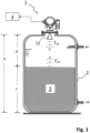
- Fig.1 a typical arrangement of a freely radiating, radar-based level measuring device 1 on a container 3 is shown.
- the container 3 contains a filling material 2, the filling level L of which is to be determined by the level measuring device 1.
- the level measuring device 1 is attached to the container 3 above the maximum permissible filling level L.
- the height h of the container 3 can be between just 30 cm and up to 125 m.
- the level measuring device 1 is connected to a higher-level unit 4, for example a process control system or a decentralized database, via a bus system, such as "Ethernet”, “PROFIBUS”, “HART” or “Wireless HART”.
- a bus system such as "Ethernet”, "PROFIBUS”, "HART” or “Wireless HART”.
- This can be used to obtain information about the operating status of the level measuring device 1.
- information about the fill level L can also be transmitted via the bus system in order to control any inflows or outflows present at the container 3.
- the level measuring device 1 shown is designed as a free-radiating radar measuring device, it comprises a corresponding transmitting/receiving antenna 12.
- the antenna 12 can, as indicated, be designed as a horn antenna, for example. Regardless of the design, the transmitting/receiving antenna 12 is aligned in such a way that a corresponding radar signal S HF is transmitted in the direction of the filling material 3 according to the FMCW or pulse transit time principle.
- the radar signal S HF is reflected on the surface of the filling material 3 and, after a corresponding signal propagation time, is received by the transmitting/receiving antenna 12 as an electrical reception signal e HF .
- two separate antennas can be used to separately transmit and receive the radar signal S HF , E HF .
- an electrically conductive probe such as a waveguide or a coaxial cable, which extends towards the bottom of the container. This embodiment is known under the term TDR (" Time Domain Reflectometry ") .
- the measuring device 1 To generate the radar signal S HF, the measuring device 1 comprises a signal generation unit 11, which generates a corresponding electrical high-frequency signal s HF and feeds it to the antenna 12.
- the frequency of the high-frequency signal s HF defines the frequency of the radar signal S HF in the microwave range. Therefore, the high-frequency signal generation unit 11, 12 must be designed to generate the electrical high-frequency signal s HF with the ramp-shaped change in its frequency required for FMCW.
- the signal generation unit 11 for generating the high-frequency signal s HF comprises a high-frequency oscillator 112 which is controlled by means of a ramp generation unit 111.
- the control takes place according to a phase control (known in English as " Phase Locked Loop, PLL" ). This stabilizes the frequency of the high-frequency oscillator 112 on the one hand.
- PLL Phase Locked Loop
- the ramp-shaped frequency change of the high-frequency signal s HF is set via this.
- the frequency of the high-frequency signal s HF increases periodically within a predefined frequency band ⁇ f at a constant rate of change.
- the periodicity of the individual frequency ramps can be in a range of several 100 ms.
- the duration of the individual ramp can be in the range between 100 ⁇ s and 100 ms.
- the position of the frequency band ⁇ f must be set taking regulatory requirements into account, which is why frequency bands around frequencies of 6 GHz, 26 GHz, 79 GHz or 120 GHz are preferably implemented as the frequency band ⁇ f.
- the bandwidth is in particular between 0.5 GHz and 10 GHz.
- the high-frequency signal s HF is not generated continuously in the case of FMCW. Rather, the ramp-shaped change is interrupted for a defined pause time after a defined number of consecutive frequency ramps. This number of consecutive frequency ramps, or their respective ramp duration, and the subsequent pause time result in the corresponding measuring rate r m with which the FMCW-based level measuring device 1 cyclically re-determines the level L.
- the cycle duration is between 0.3 Hz and 30 Hz.
- the electrical high-frequency signal s HF is fed to the antenna 12 within the signal generation unit 11 via a signal divider 116, a transmit amplifier 113 and a transmit/receive switch 114.
- the incoming radar signal E HF which is reflected from the filling material surface, is converted back into a purely electrical receive signal e HF by the transmit/receive antenna 12.
- the receive signal e HF is then processed in an evaluation unit 13 after any receive amplification (not in Fig.2 shown) is mixed with the high-frequency signal s HF to be transmitted by means of a mixer 131.
- the high-frequency signal s HF is branched off from the signal divider 116 of the signal generation unit 11.
- the frequency of the evaluation signal IF is proportional to the distance d to the filling material surface in accordance with the FMCW principle.
- an analog/digital converter of a computing unit 134 in the evaluation unit 13 digitizes the evaluation signal IF.
- the computing unit 134 can thus subject the digitized evaluation signal to a (fast) Fourier transformation, or FFT for short.
- the frequency of the global maximum of the corresponding FFT spectrum ideally corresponds to the distance d to the filling material surface.
- a signal generation unit 11 To generate the pulse-shaped high frequency signal S HF also includes the Fig.3 shown circuit of the level measuring device 1 a signal generation unit 11.
- the signal generation unit 11 is designed in such a way that it generates electrical high-frequency pulses s HF with a defined clock rate f c .
- the signal generation unit 11 in the embodiment shown comprises a first pulse generator 111, which controls a first high-frequency oscillator 112.
- the frequency of the microwave pulses S HF , E HF is determined by the oscillation frequency of the high-frequency oscillator 112.
- the high-frequency oscillator 112 can be designed as an oscillating quartz crystal.
- a VCO Voltage Controlled Oscillator
- the high-frequency oscillator 112 is controlled by the pulse generator 111 using a corresponding direct voltage signal.
- the pulse generator 111 thereby defines the pulse duration of the individual microwave pulses S HF and the clock rate f c with which the microwave pulses S HF are transmitted.
- a semiconductor-based digital oscillator is used as the high-frequency oscillator 112.
- the clock rate f c with which the individual microwave pulses s HF are excited is in practice between 100 KHz and 1 MHz.
- the high-frequency pulses s HF generated by the high-frequency oscillator 112 are fed to the antenna 12 via a transmit amplifier 113 and a transmit/receive switch 114 in a manner analogous to the FMCW method, so that they are transmitted as microwave pulses S HF .
- the transmit/receive switch 114 feeds the corresponding received signal e HF to a mixer 131 in the evaluation unit of the level measuring device 1.
- an electrically conductive probe such as a waveguide or a coaxial cable can be used instead of the antenna 12, which extends towards the bottom of the container.
- the mixer 131 is used to sub-sample the received signal e HF , which is characteristic of the pulse transit time method.
- the received signal e HF is mixed with electrical sampling pulses s' HF by the mixer 131.
- the sampling rate f' c with which the sampling pulses s' HF are generated, differs by a defined, relative deviation ⁇ of far less than 0.1 per mille from the clock rate f c of the generated high-frequency pulses s HF .
- the sampling pulses s' HF are generated in the evaluation unit 13 in a similar way to the signal generation unit 13 by a second pulse generator 133, which controls a second high-frequency oscillator 134.
- the frequency of the sampling pulses s' HF is defined by the second high-frequency oscillator 134.
- the frequency of both high-frequency oscillators 112, 134 is set identically.
- the second pulse generator 134 in turn controls the sampling rate f' c with which the sampling pulses s' HF are generated.
- an evaluation signal IF is generated which is typical for the pulse transit time method and which represents the received signal e HF in a time-stretched manner.
- the advantage of time dilation is that the evaluation signal IF is technically much easier to evaluate than the pure reception signal e HF due to the time dilation:
- the reason for this is that the reception signal e HF has a correspondingly short time scale t in the nanosecond range due to the high propagation speed of the microwave pulses S HF , E HF at the speed of light.
- the evaluation signal ZF receives a time scale in the millisecond range.
- the computing unit 132 subsequently determines the fill level L after appropriate analog/digital conversion by determining the signal maximum corresponding to the distance d in the evaluation signal IF.
- the pulse transit time-based variant of the level measuring device 1 shown in FIG. 1 each includes a transmitting amplifier 113 in its signal generating unit 11.
- this component heats up the most during measuring operation in practice. In a large number of applications, this is not critical, since the level measuring device 1 is often only used at outside temperatures or room temperatures. This allows the heat generated at the transmitting amplifier 113 to be sufficiently dissipated so that the temperature remains well below the critical junction temperature of 150 °C. However, it becomes critical when the level measuring device 1 is used at locations is used in areas where temperatures exceed 100 °C, at least temporarily, such as in cleaning processes during food production.
- the two embodiments of the level measuring device 1 which are shown in Fig. 2 and Fig. 3 described, therefore, a temperature sensor 115 which is mounted in the signal generation unit 11 on the transmitting amplifier 113 so that the temperature there can be measured.
- a temperature sensor 115 which is mounted in the signal generation unit 11 on the transmitting amplifier 113 so that the temperature there can be measured.
- the level measuring device 1 measures the fill level L below a defined limit temperature T g on the temperature sensor 115 of, for example, 100 °C with a constant or unreduced measuring rate r m , which it also measures with under normal conditions. Above the limit temperature T g , however, the level measuring device 1 reduces the measuring rate r m linearly with increasing temperature. In contrast to the illustration shown, a gradual reduction is also conceivable as opposed to a linear reduction. This primarily counteracts the heat development by the transmitting amplifier 113.
- the temperature in the level measuring device 1 does not increase above a critical maximum temperature T max of, for example, 150 °C. If the temperature sensor 115 detects that the critical maximum temperature T max is exceeded, the level measuring device 1 can, for example, switch itself off automatically if it is designed accordingly. This ensures that the level measuring device 1 does not measure any incorrect level values L and that it does not suffer any irreparable damage.
- control of the measuring rate r m according to the invention can also be used for level measuring devices 1 that do not operate according to the pulse transit time or FMCW method.
- the method according to the invention can also be generally used for radar-based distance measurement.
Landscapes
- Physics & Mathematics (AREA)
- Engineering & Computer Science (AREA)
- Radar, Positioning & Navigation (AREA)
- Remote Sensing (AREA)
- General Physics & Mathematics (AREA)
- Electromagnetism (AREA)
- Computer Networks & Wireless Communication (AREA)
- Thermal Sciences (AREA)
- Fluid Mechanics (AREA)
- Radar Systems Or Details Thereof (AREA)
- Measurement Of Levels Of Liquids Or Fluent Solid Materials (AREA)
Claims (8)
- Transmetteur de niveau basé sur un radar, lequel transmetteur est destiné à la mesure d'un niveau d'un produit (3) se trouvant dans un réservoir (2), lequel transmetteur comprend :- une unité de génération de signaux (11), laquelle est conçue pour générer un signal électrique haute fréquence (sHF) en fonction d'un taux de mesure réglable (rm),- un arrangement d'antennes (12), au moyen duquel le signal haute fréquence (sHF) peut être émis sous forme de signal radar (SHF) en direction du produit (3) et peut être reçu, après réflexion à la surface du produit (3), sous forme de signal de réception correspondant (eHF),- une unité d'évaluation (13), laquelle est conçue pour redéterminer cycliquement le niveau (L) au moins à l'aide du signal de réception (eHF) au taux de mesure réglable (rm),- un capteur de température (115), lequel est conçu pour mesurer la température sur l'unité de génération de signaux (11) et/ou sur l'unité d'évaluation (13),caractériséen ce que l'unité de génération de signaux (11) et l'unité d'évaluation (13) sont conçues pour réguler le taux de mesure (rm) en fonction de la température mesurée de telle sorte que le taux de mesure (rm) est réduit avec une température croissante au moins au-dessus d'une température limite définie (Tg), eten ce que l'unité de génération de signaux (11) et l'unité d'évaluation (13) sont conçues pour arrêter la mesure de niveau lorsque la température mesurée dépasse une température maximale prédéfinie (Tmax).
- Transmetteur de niveau selon la revendication 1, pour lequel l'unité de génération de signaux (11) et l'unité d'évaluation (13) régulent le taux de mesure (rm) en fonction de la température mesurée de telle sorte que le taux de mesure (rm) au-dessus de la température limite (Tg) est réduit de manière linéaire ou par paliers lorsque la température augmente.
- Transmetteur de niveau selon l'une des revendications précédentes, pour lequel l'unité de génération de signaux (11) et l'unité d'évaluation (13) sont conçues pour arrêter la mesure de niveau lorsque la température mesurée dépasse 150 °C.
- Transmetteur de niveau selon l'une des revendications précédentes, pour lequel au moins l'unité de génération de signaux (11) est conçue en tant que composant monolithique d'un ASIC.
- Transmetteur de niveau selon la revendication 4,pour lequel l'unité de génération de signaux (11) comprend un amplificateur d'émission (113) destiné à amplifier le signal haute fréquence (sHF), etpour lequel le capteur de température (115) est disposé sur l'amplificateur d'émission.
- Transmetteur de niveau selon l'une des revendications précédentes,pour lequel l'unité de génération de signaux (11) est conçue pour générer le signal électrique haute fréquence (sHF) selon la méthode du temps de propagation des impulsions, etpour lequel l'unité d'évaluation (13) est conçue pour déterminer le niveau (L) selon la méthode du temps de propagation des impulsions à l'aide du signal de réception échantillonné (eHF).
- Transmetteur de niveau selon la revendication 1 à 5,pour lequel l'unité de génération de signaux (11) est conçue pour générer le signal électrique haute fréquence (sHF) selon la méthode FMCW, etpour lequel l'unité d'évaluation (13) est conçue pour déterminer le niveau (L) selon la méthode FMCW en mélangeant le signal haute fréquence (sHF) et le signal de réception (eHF).
- Procédé destiné à la mesure, basée sur un radar, d'un niveau (L) d'un produit (3) se trouvant dans un réservoir (2) au moyen du transmetteur de niveau (1) selon l'une des revendications 1 à 7, lequel procédé comprend les étapes suivantes :- Génération d'un signal électrique haute fréquence (sHF) correspondant à un taux de mesure variable (rm),- Émission du signal haute fréquence (sHF) sous forme de signal radar (SHF) en direction de l'objet (2),- Réception du signal radar réfléchi (EHF) en tant que signal de réception électrique (eHF) après réflexion sur l'objet (2),- Nouvelle détermination cyclique de la distance (d) à l'aide d'au moins le signal de réception (eHF) au taux de mesure réglable (rm),- Mesure de la température sur l'unité de génération de signaux (11) et/ou sur l'unité d'évaluation (13),caractériséen ce que le taux de mesure (rm) est régulé en fonction de la température mesurée de telle sorte que le taux de mesure (rm) diminue avec l'augmentation de la température au moins au-dessus d'une température limite définie (Tg),et en ce que la mesure de niveau est arrêtée lorsque la température mesurée dépasse une température maximale prédéfinie.
Applications Claiming Priority (2)
| Application Number | Priority Date | Filing Date | Title |
|---|---|---|---|
| DE102019133245.1A DE102019133245B4 (de) | 2019-12-05 | 2019-12-05 | Füllstandsmessgerät und Verfahren zur Radar-basierten Messung eines Füllstands |
| PCT/EP2020/082849 WO2021110432A1 (fr) | 2019-12-05 | 2020-11-20 | Dispositif de mesure de niveau de remplissage |
Publications (2)
| Publication Number | Publication Date |
|---|---|
| EP4070048A1 EP4070048A1 (fr) | 2022-10-12 |
| EP4070048B1 true EP4070048B1 (fr) | 2024-05-22 |
Family
ID=73543253
Family Applications (1)
| Application Number | Title | Priority Date | Filing Date |
|---|---|---|---|
| EP20811281.3A Active EP4070048B1 (fr) | 2019-12-05 | 2020-11-20 | Appareil de mesure de niveau |
Country Status (5)
| Country | Link |
|---|---|
| US (1) | US20230011123A1 (fr) |
| EP (1) | EP4070048B1 (fr) |
| CN (1) | CN114761767A (fr) |
| DE (1) | DE102019133245B4 (fr) |
| WO (1) | WO2021110432A1 (fr) |
Citations (2)
| Publication number | Priority date | Publication date | Assignee | Title |
|---|---|---|---|---|
| DE102006058852B4 (de) * | 2006-12-13 | 2014-01-02 | Vega Grieshaber Kg | Verfahren und Vorrichtung zur Korrektur nichtidealer Zwischenfrequenzsignale bei Abstandsmessgeräten nach dem FMCW-Prinzip |
| WO2017137136A1 (fr) * | 2016-02-12 | 2017-08-17 | Robert Bosch Gmbh | Capteur radar pour systèmes d'aide à la conduite dans des véhicules à moteur |
Family Cites Families (23)
| Publication number | Priority date | Publication date | Assignee | Title |
|---|---|---|---|---|
| US8970234B2 (en) * | 2011-09-26 | 2015-03-03 | Apple Inc. | Threshold-based temperature-dependent power/thermal management with temperature sensor calibration |
| DE102012101725A1 (de) * | 2012-03-01 | 2013-09-05 | Sick Ag | Verfahren zur Füllstandsmessung |
| DE102012103493A1 (de) * | 2012-04-20 | 2013-10-24 | Endress + Hauser Gmbh + Co. | Vorrichtung zur Bestimmung des Füllstandes eines Füllguts in einem Behälter |
| DE102012104858A1 (de) * | 2012-06-05 | 2013-12-05 | Endress + Hauser Gmbh + Co. Kg | Verfahren zur Füllstandsmessung nach dem Laufzeitprinzip |
| DE102012112749A1 (de) * | 2012-12-20 | 2014-07-10 | Endress + Hauser Gmbh + Co. Kg | Verfahren zur Auswertung von Messsignalen eines Füllstandsmessgeräts |
| DE102013108490A1 (de) * | 2013-08-07 | 2015-02-12 | Endress + Hauser Gmbh + Co. Kg | Dispersionskorrektur für FMCW-Radar in einem Rohr |
| DE102014101410A1 (de) * | 2014-02-05 | 2015-08-06 | Endress + Hauser Gmbh + Co. Kg | Vorrichtung zur Bestimmung oder Überwachung des Füllstands eines in einemBehälter gelagerten Füllguts |
| US9442184B2 (en) * | 2014-02-21 | 2016-09-13 | Nxp B.V. | Functional safety monitor pin |
| KR20150108681A (ko) * | 2014-03-18 | 2015-09-30 | 주식회사 만도 | 차량용 레이더 장치 및 제어 방법 |
| US9818209B2 (en) * | 2015-04-02 | 2017-11-14 | Rosemount Tank Radar Ab | User interface for radar level gauge analysis |
| WO2017015188A1 (fr) * | 2015-07-20 | 2017-01-26 | 3M Innovative Properties Company | Dispositif de rayonnement actinique pour le durcissement rapide de résine |
| CN105865574A (zh) * | 2016-04-11 | 2016-08-17 | 北京吉泰凯士仪表科技有限公司 | 热式液位计 |
| DE102016108594B3 (de) * | 2016-05-10 | 2017-11-02 | Endress + Hauser Gmbh + Co. Kg | Verfahren zur Ermittlung des Füllstandes sowie zur Ermittlung zumindest einer Zusatzinformation |
| DE102016113268B4 (de) * | 2016-07-19 | 2018-06-07 | Endress+Hauser SE+Co. KG | Verfahren und Sicherheitsschaltung zur sicheren Begrenzung der elektrischen Leistungsaufnahme |
| WO2018117155A1 (fr) * | 2016-12-22 | 2018-06-28 | 古河電気工業株式会社 | Dispositif de génération d'impulsions et procédé de réglage de sortie correspondant |
| EP3388801B1 (fr) * | 2017-04-11 | 2020-06-10 | NXP USA, Inc. | Système de capteur de température, dispositif radar et procédé associé |
| DE102017117900A1 (de) * | 2017-08-07 | 2019-02-07 | Endress+Hauser SE+Co. KG | Hochfrequenz-Signalerzeugungseinheit |
| HUE053290T2 (hu) * | 2017-10-06 | 2021-06-28 | Grieshaber Vega Kg | Radar töltöttségi szintet mérõ eszköz chipen |
| EP3467447B1 (fr) * | 2017-10-06 | 2019-09-25 | VEGA Grieshaber KG | Appareil de mesure de niveau de remplissage à une pluralité des chips radar |
| HUE046126T2 (hu) * | 2017-10-06 | 2020-02-28 | Grieshaber Vega Kg | Radaros szintmérõ radarlapkával egy áramköri lap különbözõ szintjein |
| EP3692343B1 (fr) * | 2017-10-06 | 2022-10-05 | VEGA Grieshaber KG | Jauge de niveau avec système radar |
| DE102018102367B4 (de) * | 2018-02-02 | 2026-02-19 | Endress+Hauser SE+Co. KG | Verfahren zur Detektion von potentiellen Fehlerzuständen an einem FMCW-basierten Füllstandsmessgerät |
| US11520332B1 (en) * | 2019-12-03 | 2022-12-06 | Amazon Technologies, Inc. | System for automated exploration by an autonomous mobile device using markers based on image features |
-
2019
- 2019-12-05 DE DE102019133245.1A patent/DE102019133245B4/de active Active
-
2020
- 2020-11-20 CN CN202080083771.5A patent/CN114761767A/zh active Pending
- 2020-11-20 EP EP20811281.3A patent/EP4070048B1/fr active Active
- 2020-11-20 WO PCT/EP2020/082849 patent/WO2021110432A1/fr not_active Ceased
- 2020-11-20 US US17/756,816 patent/US20230011123A1/en not_active Abandoned
Patent Citations (2)
| Publication number | Priority date | Publication date | Assignee | Title |
|---|---|---|---|---|
| DE102006058852B4 (de) * | 2006-12-13 | 2014-01-02 | Vega Grieshaber Kg | Verfahren und Vorrichtung zur Korrektur nichtidealer Zwischenfrequenzsignale bei Abstandsmessgeräten nach dem FMCW-Prinzip |
| WO2017137136A1 (fr) * | 2016-02-12 | 2017-08-17 | Robert Bosch Gmbh | Capteur radar pour systèmes d'aide à la conduite dans des véhicules à moteur |
Also Published As
| Publication number | Publication date |
|---|---|
| WO2021110432A1 (fr) | 2021-06-10 |
| EP4070048A1 (fr) | 2022-10-12 |
| CN114761767A (zh) | 2022-07-15 |
| DE102019133245B4 (de) | 2021-06-24 |
| DE102019133245A1 (de) | 2021-06-10 |
| US20230011123A1 (en) | 2023-01-12 |
Similar Documents
| Publication | Publication Date | Title |
|---|---|---|
| DE69730416T2 (de) | Füllstandmessradargerät | |
| EP3308110B1 (fr) | Procédé et dispositif pour contrôler la fonctionnalité d'un appareil de mesure du niveau de remplissage basé sur un radar | |
| EP3746753B1 (fr) | Procédé de détection d'états d'erreur potentiels sur un dispositif de mesure de remplissage à base de fmcw | |
| EP3857184A1 (fr) | Détection des états en fonction de l'événement lors de la mesure du niveau de remplissage | |
| EP4065937B1 (fr) | Dispositif de mesure de distance basé sur une fmcw | |
| WO2023165840A1 (fr) | Compteur de niveau de remplissage | |
| EP4070048B1 (fr) | Appareil de mesure de niveau | |
| DE102018132739B4 (de) | Verfahren zur FMCW-basierten Abstandsmessung | |
| EP3857182B1 (fr) | Jauge de niveau | |
| DE102019132354A1 (de) | FMCW-basiertes Abstandsmessgerät | |
| EP3887777B1 (fr) | Procédé de mesure du niveau de remplissage | |
| WO2023151929A1 (fr) | Mesure combinée de niveau de remplissage et de température | |
| DE102022105195A1 (de) | Füllstandsmessgerät | |
| WO2016202533A1 (fr) | Procédé et dispositif de détermination du niveau de remplissage d'un produit de remplissage dans un récipient | |
| EP4244646B1 (fr) | Dispositif de mesure de niveau de remplissage | |
| DE102005049500A1 (de) | Verfahren zur Bestimmung des Füllstands anhand der Laufzeit eines hochfrequenten Messsignals | |
| DE102022128393A1 (de) | Ortsauflösende Füllstandsmessung | |
| EP3874242B1 (fr) | Appareil de mesure de niveau de remplissage | |
| EP3837509B1 (fr) | Dispositif de mesure de niveau de remplissage | |
| WO2019233704A1 (fr) | Appareil de mesure de niveau à base de radar | |
| WO2018219534A1 (fr) | Unité de production haute fréquence | |
| DE102024113818A1 (de) | Füllstandsmessgerät |
Legal Events
| Date | Code | Title | Description |
|---|---|---|---|
| STAA | Information on the status of an ep patent application or granted ep patent |
Free format text: STATUS: UNKNOWN |
|
| STAA | Information on the status of an ep patent application or granted ep patent |
Free format text: STATUS: THE INTERNATIONAL PUBLICATION HAS BEEN MADE |
|
| TPAC | Observations filed by third parties |
Free format text: ORIGINAL CODE: EPIDOSNTIPA |
|
| PUAI | Public reference made under article 153(3) epc to a published international application that has entered the european phase |
Free format text: ORIGINAL CODE: 0009012 |
|
| STAA | Information on the status of an ep patent application or granted ep patent |
Free format text: STATUS: REQUEST FOR EXAMINATION WAS MADE |
|
| 17P | Request for examination filed |
Effective date: 20220518 |
|
| AK | Designated contracting states |
Kind code of ref document: A1 Designated state(s): AL AT BE BG CH CY CZ DE DK EE ES FI FR GB GR HR HU IE IS IT LI LT LU LV MC MK MT NL NO PL PT RO RS SE SI SK SM TR |
|
| DAV | Request for validation of the european patent (deleted) | ||
| DAX | Request for extension of the european patent (deleted) | ||
| STAA | Information on the status of an ep patent application or granted ep patent |
Free format text: STATUS: EXAMINATION IS IN PROGRESS |
|
| 17Q | First examination report despatched |
Effective date: 20230605 |
|
| GRAP | Despatch of communication of intention to grant a patent |
Free format text: ORIGINAL CODE: EPIDOSNIGR1 |
|
| STAA | Information on the status of an ep patent application or granted ep patent |
Free format text: STATUS: GRANT OF PATENT IS INTENDED |
|
| RIC1 | Information provided on ipc code assigned before grant |
Ipc: G01S 13/88 20060101ALI20240115BHEP Ipc: G01S 13/86 20060101ALI20240115BHEP Ipc: G01F 23/284 20060101AFI20240115BHEP |
|
| INTG | Intention to grant announced |
Effective date: 20240129 |
|
| GRAS | Grant fee paid |
Free format text: ORIGINAL CODE: EPIDOSNIGR3 |
|
| GRAA | (expected) grant |
Free format text: ORIGINAL CODE: 0009210 |
|
| STAA | Information on the status of an ep patent application or granted ep patent |
Free format text: STATUS: THE PATENT HAS BEEN GRANTED |
|
| AK | Designated contracting states |
Kind code of ref document: B1 Designated state(s): AL AT BE BG CH CY CZ DE DK EE ES FI FR GB GR HR HU IE IS IT LI LT LU LV MC MK MT NL NO PL PT RO RS SE SI SK SM TR |
|
| REG | Reference to a national code |
Ref country code: GB Ref legal event code: FG4D Free format text: NOT ENGLISH |
|
| REG | Reference to a national code |
Ref country code: CH Ref legal event code: EP |
|
| REG | Reference to a national code |
Ref country code: DE Ref legal event code: R096 Ref document number: 502020008091 Country of ref document: DE |
|
| REG | Reference to a national code |
Ref country code: IE Ref legal event code: FG4D Free format text: LANGUAGE OF EP DOCUMENT: GERMAN |
|
| REG | Reference to a national code |
Ref country code: LT Ref legal event code: MG9D |
|
| REG | Reference to a national code |
Ref country code: NL Ref legal event code: MP Effective date: 20240522 |
|
| P01 | Opt-out of the competence of the unified patent court (upc) registered |
Free format text: CASE NUMBER: APP_48901/2024 Effective date: 20240827 |
|
| PG25 | Lapsed in a contracting state [announced via postgrant information from national office to epo] |
Ref country code: IS Free format text: LAPSE BECAUSE OF FAILURE TO SUBMIT A TRANSLATION OF THE DESCRIPTION OR TO PAY THE FEE WITHIN THE PRESCRIBED TIME-LIMIT Effective date: 20240922 |
|
| PG25 | Lapsed in a contracting state [announced via postgrant information from national office to epo] |
Ref country code: BG Free format text: LAPSE BECAUSE OF FAILURE TO SUBMIT A TRANSLATION OF THE DESCRIPTION OR TO PAY THE FEE WITHIN THE PRESCRIBED TIME-LIMIT Effective date: 20240522 |
|
| PG25 | Lapsed in a contracting state [announced via postgrant information from national office to epo] |
Ref country code: FI Free format text: LAPSE BECAUSE OF FAILURE TO SUBMIT A TRANSLATION OF THE DESCRIPTION OR TO PAY THE FEE WITHIN THE PRESCRIBED TIME-LIMIT Effective date: 20240522 Ref country code: HR Free format text: LAPSE BECAUSE OF FAILURE TO SUBMIT A TRANSLATION OF THE DESCRIPTION OR TO PAY THE FEE WITHIN THE PRESCRIBED TIME-LIMIT Effective date: 20240522 |
|
| PG25 | Lapsed in a contracting state [announced via postgrant information from national office to epo] |
Ref country code: GR Free format text: LAPSE BECAUSE OF FAILURE TO SUBMIT A TRANSLATION OF THE DESCRIPTION OR TO PAY THE FEE WITHIN THE PRESCRIBED TIME-LIMIT Effective date: 20240823 |
|
| PG25 | Lapsed in a contracting state [announced via postgrant information from national office to epo] |
Ref country code: PT Free format text: LAPSE BECAUSE OF FAILURE TO SUBMIT A TRANSLATION OF THE DESCRIPTION OR TO PAY THE FEE WITHIN THE PRESCRIBED TIME-LIMIT Effective date: 20240923 |
|
| PG25 | Lapsed in a contracting state [announced via postgrant information from national office to epo] |
Ref country code: NL Free format text: LAPSE BECAUSE OF FAILURE TO SUBMIT A TRANSLATION OF THE DESCRIPTION OR TO PAY THE FEE WITHIN THE PRESCRIBED TIME-LIMIT Effective date: 20240522 |
|
| PG25 | Lapsed in a contracting state [announced via postgrant information from national office to epo] |
Ref country code: ES Free format text: LAPSE BECAUSE OF FAILURE TO SUBMIT A TRANSLATION OF THE DESCRIPTION OR TO PAY THE FEE WITHIN THE PRESCRIBED TIME-LIMIT Effective date: 20240522 |
|
| PG25 | Lapsed in a contracting state [announced via postgrant information from national office to epo] |
Ref country code: PL Free format text: LAPSE BECAUSE OF FAILURE TO SUBMIT A TRANSLATION OF THE DESCRIPTION OR TO PAY THE FEE WITHIN THE PRESCRIBED TIME-LIMIT Effective date: 20240522 |
|
| PG25 | Lapsed in a contracting state [announced via postgrant information from national office to epo] |
Ref country code: LV Free format text: LAPSE BECAUSE OF FAILURE TO SUBMIT A TRANSLATION OF THE DESCRIPTION OR TO PAY THE FEE WITHIN THE PRESCRIBED TIME-LIMIT Effective date: 20240522 |
|
| PG25 | Lapsed in a contracting state [announced via postgrant information from national office to epo] |
Ref country code: PT Free format text: LAPSE BECAUSE OF FAILURE TO SUBMIT A TRANSLATION OF THE DESCRIPTION OR TO PAY THE FEE WITHIN THE PRESCRIBED TIME-LIMIT Effective date: 20240923 Ref country code: PL Free format text: LAPSE BECAUSE OF FAILURE TO SUBMIT A TRANSLATION OF THE DESCRIPTION OR TO PAY THE FEE WITHIN THE PRESCRIBED TIME-LIMIT Effective date: 20240522 Ref country code: NO Free format text: LAPSE BECAUSE OF FAILURE TO SUBMIT A TRANSLATION OF THE DESCRIPTION OR TO PAY THE FEE WITHIN THE PRESCRIBED TIME-LIMIT Effective date: 20240822 Ref country code: NL Free format text: LAPSE BECAUSE OF FAILURE TO SUBMIT A TRANSLATION OF THE DESCRIPTION OR TO PAY THE FEE WITHIN THE PRESCRIBED TIME-LIMIT Effective date: 20240522 Ref country code: LV Free format text: LAPSE BECAUSE OF FAILURE TO SUBMIT A TRANSLATION OF THE DESCRIPTION OR TO PAY THE FEE WITHIN THE PRESCRIBED TIME-LIMIT Effective date: 20240522 Ref country code: IS Free format text: LAPSE BECAUSE OF FAILURE TO SUBMIT A TRANSLATION OF THE DESCRIPTION OR TO PAY THE FEE WITHIN THE PRESCRIBED TIME-LIMIT Effective date: 20240922 Ref country code: HR Free format text: LAPSE BECAUSE OF FAILURE TO SUBMIT A TRANSLATION OF THE DESCRIPTION OR TO PAY THE FEE WITHIN THE PRESCRIBED TIME-LIMIT Effective date: 20240522 Ref country code: GR Free format text: LAPSE BECAUSE OF FAILURE TO SUBMIT A TRANSLATION OF THE DESCRIPTION OR TO PAY THE FEE WITHIN THE PRESCRIBED TIME-LIMIT Effective date: 20240823 Ref country code: FI Free format text: LAPSE BECAUSE OF FAILURE TO SUBMIT A TRANSLATION OF THE DESCRIPTION OR TO PAY THE FEE WITHIN THE PRESCRIBED TIME-LIMIT Effective date: 20240522 Ref country code: ES Free format text: LAPSE BECAUSE OF FAILURE TO SUBMIT A TRANSLATION OF THE DESCRIPTION OR TO PAY THE FEE WITHIN THE PRESCRIBED TIME-LIMIT Effective date: 20240522 Ref country code: BG Free format text: LAPSE BECAUSE OF FAILURE TO SUBMIT A TRANSLATION OF THE DESCRIPTION OR TO PAY THE FEE WITHIN THE PRESCRIBED TIME-LIMIT Effective date: 20240522 Ref country code: RS Free format text: LAPSE BECAUSE OF FAILURE TO SUBMIT A TRANSLATION OF THE DESCRIPTION OR TO PAY THE FEE WITHIN THE PRESCRIBED TIME-LIMIT Effective date: 20240822 |
|
| PG25 | Lapsed in a contracting state [announced via postgrant information from national office to epo] |
Ref country code: DK Free format text: LAPSE BECAUSE OF FAILURE TO SUBMIT A TRANSLATION OF THE DESCRIPTION OR TO PAY THE FEE WITHIN THE PRESCRIBED TIME-LIMIT Effective date: 20240522 |
|
| PG25 | Lapsed in a contracting state [announced via postgrant information from national office to epo] |
Ref country code: EE Free format text: LAPSE BECAUSE OF FAILURE TO SUBMIT A TRANSLATION OF THE DESCRIPTION OR TO PAY THE FEE WITHIN THE PRESCRIBED TIME-LIMIT Effective date: 20240522 |
|
| PG25 | Lapsed in a contracting state [announced via postgrant information from national office to epo] |
Ref country code: CZ Free format text: LAPSE BECAUSE OF FAILURE TO SUBMIT A TRANSLATION OF THE DESCRIPTION OR TO PAY THE FEE WITHIN THE PRESCRIBED TIME-LIMIT Effective date: 20240522 |
|
| PG25 | Lapsed in a contracting state [announced via postgrant information from national office to epo] |
Ref country code: SK Free format text: LAPSE BECAUSE OF FAILURE TO SUBMIT A TRANSLATION OF THE DESCRIPTION OR TO PAY THE FEE WITHIN THE PRESCRIBED TIME-LIMIT Effective date: 20240522 Ref country code: RO Free format text: LAPSE BECAUSE OF FAILURE TO SUBMIT A TRANSLATION OF THE DESCRIPTION OR TO PAY THE FEE WITHIN THE PRESCRIBED TIME-LIMIT Effective date: 20240522 |
|
| PG25 | Lapsed in a contracting state [announced via postgrant information from national office to epo] |
Ref country code: SK Free format text: LAPSE BECAUSE OF FAILURE TO SUBMIT A TRANSLATION OF THE DESCRIPTION OR TO PAY THE FEE WITHIN THE PRESCRIBED TIME-LIMIT Effective date: 20240522 Ref country code: RO Free format text: LAPSE BECAUSE OF FAILURE TO SUBMIT A TRANSLATION OF THE DESCRIPTION OR TO PAY THE FEE WITHIN THE PRESCRIBED TIME-LIMIT Effective date: 20240522 Ref country code: EE Free format text: LAPSE BECAUSE OF FAILURE TO SUBMIT A TRANSLATION OF THE DESCRIPTION OR TO PAY THE FEE WITHIN THE PRESCRIBED TIME-LIMIT Effective date: 20240522 Ref country code: DK Free format text: LAPSE BECAUSE OF FAILURE TO SUBMIT A TRANSLATION OF THE DESCRIPTION OR TO PAY THE FEE WITHIN THE PRESCRIBED TIME-LIMIT Effective date: 20240522 Ref country code: CZ Free format text: LAPSE BECAUSE OF FAILURE TO SUBMIT A TRANSLATION OF THE DESCRIPTION OR TO PAY THE FEE WITHIN THE PRESCRIBED TIME-LIMIT Effective date: 20240522 |
|
| REG | Reference to a national code |
Ref country code: DE Ref legal event code: R097 Ref document number: 502020008091 Country of ref document: DE |
|
| PLBE | No opposition filed within time limit |
Free format text: ORIGINAL CODE: 0009261 |
|
| STAA | Information on the status of an ep patent application or granted ep patent |
Free format text: STATUS: NO OPPOSITION FILED WITHIN TIME LIMIT |
|
| PG25 | Lapsed in a contracting state [announced via postgrant information from national office to epo] |
Ref country code: SI Free format text: LAPSE BECAUSE OF FAILURE TO SUBMIT A TRANSLATION OF THE DESCRIPTION OR TO PAY THE FEE WITHIN THE PRESCRIBED TIME-LIMIT Effective date: 20240522 |
|
| 26N | No opposition filed |
Effective date: 20250225 |
|
| REG | Reference to a national code |
Ref country code: DE Ref legal event code: R119 Ref document number: 502020008091 Country of ref document: DE |
|
| REG | Reference to a national code |
Ref country code: CH Ref legal event code: PL |
|
| PG25 | Lapsed in a contracting state [announced via postgrant information from national office to epo] |
Ref country code: MC Free format text: LAPSE BECAUSE OF FAILURE TO SUBMIT A TRANSLATION OF THE DESCRIPTION OR TO PAY THE FEE WITHIN THE PRESCRIBED TIME-LIMIT Effective date: 20240522 |
|
| PG25 | Lapsed in a contracting state [announced via postgrant information from national office to epo] |
Ref country code: LU Free format text: LAPSE BECAUSE OF NON-PAYMENT OF DUE FEES Effective date: 20241120 |
|
| REG | Reference to a national code |
Ref country code: CH Ref legal event code: PL |
|
| GBPC | Gb: european patent ceased through non-payment of renewal fee |
Effective date: 20241120 |
|
| PG25 | Lapsed in a contracting state [announced via postgrant information from national office to epo] |
Ref country code: CH Free format text: LAPSE BECAUSE OF NON-PAYMENT OF DUE FEES Effective date: 20241130 |
|
| REG | Reference to a national code |
Ref country code: BE Ref legal event code: MM Effective date: 20241130 |
|
| PG25 | Lapsed in a contracting state [announced via postgrant information from national office to epo] |
Ref country code: SE Free format text: LAPSE BECAUSE OF FAILURE TO SUBMIT A TRANSLATION OF THE DESCRIPTION OR TO PAY THE FEE WITHIN THE PRESCRIBED TIME-LIMIT Effective date: 20240522 |
|
| PG25 | Lapsed in a contracting state [announced via postgrant information from national office to epo] |
Ref country code: DE Free format text: LAPSE BECAUSE OF NON-PAYMENT OF DUE FEES Effective date: 20250603 |
|
| PG25 | Lapsed in a contracting state [announced via postgrant information from national office to epo] |
Ref country code: BE Free format text: LAPSE BECAUSE OF NON-PAYMENT OF DUE FEES Effective date: 20241130 Ref country code: GB Free format text: LAPSE BECAUSE OF NON-PAYMENT OF DUE FEES Effective date: 20241120 |
|
| PG25 | Lapsed in a contracting state [announced via postgrant information from national office to epo] |
Ref country code: IE Free format text: LAPSE BECAUSE OF NON-PAYMENT OF DUE FEES Effective date: 20241120 |
|
| PGFP | Annual fee paid to national office [announced via postgrant information from national office to epo] |
Ref country code: AT Payment date: 20260113 Year of fee payment: 5 |
|
| PGFP | Annual fee paid to national office [announced via postgrant information from national office to epo] |
Ref country code: IT Payment date: 20251125 Year of fee payment: 6 |
|
| PGFP | Annual fee paid to national office [announced via postgrant information from national office to epo] |
Ref country code: FR Payment date: 20251126 Year of fee payment: 6 |
|
| PG25 | Lapsed in a contracting state [announced via postgrant information from national office to epo] |
Ref country code: HU Free format text: LAPSE BECAUSE OF FAILURE TO SUBMIT A TRANSLATION OF THE DESCRIPTION OR TO PAY THE FEE WITHIN THE PRESCRIBED TIME-LIMIT; INVALID AB INITIO Effective date: 20201120 |
|
| PG25 | Lapsed in a contracting state [announced via postgrant information from national office to epo] |
Ref country code: CY Free format text: LAPSE BECAUSE OF FAILURE TO SUBMIT A TRANSLATION OF THE DESCRIPTION OR TO PAY THE FEE WITHIN THE PRESCRIBED TIME-LIMIT; INVALID AB INITIO Effective date: 20201120 |
|
| PG25 | Lapsed in a contracting state [announced via postgrant information from national office to epo] |
Ref country code: SM Free format text: LAPSE BECAUSE OF FAILURE TO SUBMIT A TRANSLATION OF THE DESCRIPTION OR TO PAY THE FEE WITHIN THE PRESCRIBED TIME-LIMIT; INVALID AB INITIO Effective date: 20201120 |