WO2018117155A1 - Dispositif de génération d'impulsions et procédé de réglage de sortie correspondant - Google Patents
Dispositif de génération d'impulsions et procédé de réglage de sortie correspondant Download PDFInfo
- Publication number
- WO2018117155A1 WO2018117155A1 PCT/JP2017/045737 JP2017045737W WO2018117155A1 WO 2018117155 A1 WO2018117155 A1 WO 2018117155A1 JP 2017045737 W JP2017045737 W JP 2017045737W WO 2018117155 A1 WO2018117155 A1 WO 2018117155A1
- Authority
- WO
- WIPO (PCT)
- Prior art keywords
- output
- pulse
- adjusting
- frequency
- frequency oscillator
- Prior art date
- Legal status (The legal status is an assumption and is not a legal conclusion. Google has not performed a legal analysis and makes no representation as to the accuracy of the status listed.)
- Ceased
Links
Images




Classifications
-
- G—PHYSICS
- G01—MEASURING; TESTING
- G01S—RADIO DIRECTION-FINDING; RADIO NAVIGATION; DETERMINING DISTANCE OR VELOCITY BY USE OF RADIO WAVES; LOCATING OR PRESENCE-DETECTING BY USE OF THE REFLECTION OR RERADIATION OF RADIO WAVES; ANALOGOUS ARRANGEMENTS USING OTHER WAVES
- G01S7/00—Details of systems according to groups G01S13/00, G01S15/00, G01S17/00
- G01S7/02—Details of systems according to groups G01S13/00, G01S15/00, G01S17/00 of systems according to group G01S13/00
- G01S7/28—Details of pulse systems
- G01S7/282—Transmitters
-
- G—PHYSICS
- G01—MEASURING; TESTING
- G01S—RADIO DIRECTION-FINDING; RADIO NAVIGATION; DETERMINING DISTANCE OR VELOCITY BY USE OF RADIO WAVES; LOCATING OR PRESENCE-DETECTING BY USE OF THE REFLECTION OR RERADIATION OF RADIO WAVES; ANALOGOUS ARRANGEMENTS USING OTHER WAVES
- G01S13/00—Systems using the reflection or reradiation of radio waves, e.g. radar systems; Analogous systems using reflection or reradiation of waves whose nature or wavelength is irrelevant or unspecified
- G01S13/86—Combinations of radar systems with non-radar systems, e.g. sonar, direction finder
-
- G—PHYSICS
- G01—MEASURING; TESTING
- G01S—RADIO DIRECTION-FINDING; RADIO NAVIGATION; DETERMINING DISTANCE OR VELOCITY BY USE OF RADIO WAVES; LOCATING OR PRESENCE-DETECTING BY USE OF THE REFLECTION OR RERADIATION OF RADIO WAVES; ANALOGOUS ARRANGEMENTS USING OTHER WAVES
- G01S13/00—Systems using the reflection or reradiation of radio waves, e.g. radar systems; Analogous systems using reflection or reradiation of waves whose nature or wavelength is irrelevant or unspecified
- G01S13/88—Radar or analogous systems specially adapted for specific applications
- G01S13/93—Radar or analogous systems specially adapted for specific applications for anti-collision purposes
- G01S13/931—Radar or analogous systems specially adapted for specific applications for anti-collision purposes of land vehicles
-
- G—PHYSICS
- G01—MEASURING; TESTING
- G01S—RADIO DIRECTION-FINDING; RADIO NAVIGATION; DETERMINING DISTANCE OR VELOCITY BY USE OF RADIO WAVES; LOCATING OR PRESENCE-DETECTING BY USE OF THE REFLECTION OR RERADIATION OF RADIO WAVES; ANALOGOUS ARRANGEMENTS USING OTHER WAVES
- G01S7/00—Details of systems according to groups G01S13/00, G01S15/00, G01S17/00
- G01S7/02—Details of systems according to groups G01S13/00, G01S15/00, G01S17/00 of systems according to group G01S13/00
- G01S7/40—Means for monitoring or calibrating
-
- G—PHYSICS
- G01—MEASURING; TESTING
- G01K—MEASURING TEMPERATURE; MEASURING QUANTITY OF HEAT; THERMALLY-SENSITIVE ELEMENTS NOT OTHERWISE PROVIDED FOR
- G01K1/00—Details of thermometers not specially adapted for particular types of thermometer
- G01K1/14—Supports; Fastening devices; Arrangements for mounting thermometers in particular locations
-
- G—PHYSICS
- G01—MEASURING; TESTING
- G01S—RADIO DIRECTION-FINDING; RADIO NAVIGATION; DETERMINING DISTANCE OR VELOCITY BY USE OF RADIO WAVES; LOCATING OR PRESENCE-DETECTING BY USE OF THE REFLECTION OR RERADIATION OF RADIO WAVES; ANALOGOUS ARRANGEMENTS USING OTHER WAVES
- G01S7/00—Details of systems according to groups G01S13/00, G01S15/00, G01S17/00
- G01S7/02—Details of systems according to groups G01S13/00, G01S15/00, G01S17/00 of systems according to group G01S13/00
- G01S7/40—Means for monitoring or calibrating
- G01S7/4004—Means for monitoring or calibrating of parts of a radar system
- G01S7/4008—Means for monitoring or calibrating of parts of a radar system of transmitters
- G01S7/4013—Means for monitoring or calibrating of parts of a radar system of transmitters involving adjustment of the transmitted power
Definitions
- the present invention relates to a pulse generation device used in a radar or the like that measures the distance to an object by emitting an impulse by radio waves, and an output adjustment method used in the pulse generation device.
- a general high-frequency pulse generator used for a radar device or the like generates a pulse having a predetermined pulse width by a pulse generator, and inputs the pulse to a low-pass filter having a predetermined frequency characteristic to adjust the shape and the like.
- a pulse is generated, the pulse is input to a modulator, and a high frequency pulse is generated and output by multiplying the pulse with a carrier wave input to the modulator from a high frequency oscillator having a predetermined frequency.
- the generated high frequency pulse is radiated from the transmitting antenna and used for measuring the distance to the object.
- the pulse input to the low-pass filter is a pulse train composed of two or more pulses, and this pulse train is adjusted.
- a technique for suitably adjusting a pulse pattern of a high-frequency pulse is disclosed.
- the pulse pattern may change due to the temperature characteristics of the built-in high-frequency oscillator or modulator, the output decrease due to aging, and the like. Overseas, since it is exposed to a temperature change of about ⁇ 40 ° C. to 90 ° C.
- the pulse pattern of the high-frequency pulse changes greatly from a state in which it is suitably adjusted (for example, at normal temperature and humidity)
- a radar device When mounted on a radar device, there is a risk of non-detection or false detection of an object, deviation from legal regulations, interference with other wireless devices, and the like.
- the reflected wave from a distant object is also detected with a relatively large intensity. Therefore, when the reflecting object exists at a distance corresponding to the transmission repetition period, its reflection The waves are mixed into the received signal as so-called multi-order echoes. As a result, the distance to the object is calculated on the basis of multi-order echoes, thereby causing a problem of being detected shorter than actual (false detection).
- the high-frequency pulse signal output from the pulse generator is coupled between the transmitting and receiving antennas and becomes a noise (background signal) of the received signal of the radar device.
- a noise background signal
- the noise also increases, and the increase is increased in the radar device.
- the A / D converter is saturated, a reflected wave from a nearby object is buried in noise, causing a problem that the object is not detected (undetected).
- the output of the pulse generator increases, it may deviate from legal regulations and may cause interference with other wireless devices.
- the high-frequency pulse that is the output of the pulse generator greatly changes from the adjusted state at the time of shipment, it causes various problems. There is a risk of causing an unexpected accident due to detection or non-detection, or causing interference with other radio devices.
- the present invention has been made paying attention to the above-described problems, and includes a pulse generation device capable of adjusting an output within a predetermined range even when a change in operating temperature or aging occurs, and the output adjustment method.
- the purpose is to provide.
- a pulse generation device for an on-vehicle radar that outputs a high-frequency pulse having a main lobe and a side lobe, and a high-frequency oscillator that generates a carrier wave of a predetermined frequency;
- An output variable device that adjusts the output of the high-frequency oscillator, a power measurement unit that measures the output of the high-frequency oscillator, a temperature measurement unit that measures the ambient temperature, a baseband pulse generation unit that generates a pulse-shaped signal,
- a modulator that modulates the output of the high-frequency oscillator with the pulse-shaped signal, and when the ambient temperature is equal to or lower than a first threshold value, the output that causes the side lobe to be equal to or lower than a predetermined output or the pulse It is characterized by adjusting at least one of the shapes.
- another aspect of the pulse generator according to the present invention includes a high frequency oscillator that generates a carrier wave of a predetermined frequency, an output variable device that adjusts an output of the high frequency oscillator, and an output of the high frequency oscillator.
- a power measurement unit that measures the ambient temperature, a temperature measurement unit that measures the ambient temperature, a pulse generator that generates a pulse with a predetermined pulse width, and a low-pass filter that adjusts the shape of the pulse output from the pulse generator
- a baseband pulse generator that generates a pulse-shaped signal
- the pulse generation device When the ambient temperature exceeds the first threshold value, the pulse generation device outputs the output of the power as a high frequency pulse.
- the output variable adjusts the output of the high-frequency oscillator and the ambient temperature is equal to or lower than the first threshold, the output variable depends on the measurement result of the temperature measurement unit. Adjusting the output of the high-frequency pulse within a predetermined range by adjusting at least one of adjusting the output of the pulse-shaped signal and adjusting the shape of the pulse-shaped signal by the baseband pulse generator.
- the pulse generator according to the present invention is configured such that, when the ambient temperature exceeds the first threshold, the output variable device is the high-frequency oscillator according to the measurement result of the power measurement unit.
- the output variable device adjusts the output of the high-frequency oscillator according to the measurement result of the temperature measurement unit when the ambient temperature is equal to or lower than the first threshold value, the temperature measurement is performed.
- the variation amount of the output of the high-frequency oscillator adjusted according to the measurement result of the unit is larger than the variation amount of the output of the high-frequency oscillator adjusted according to the measurement result of the power measurement unit.
- the pulse generator according to the present invention is configured such that, when the ambient temperature exceeds the first threshold, the output variable device is the high-frequency oscillator according to the measurement result of the power measurement unit.
- the output of the high frequency oscillator is adjusted according to the measurement result of the temperature measurement unit when the ambient temperature is equal to or lower than the first threshold, the output of the high frequency oscillator is adjusted according to the measurement result of the temperature measurement unit.
- the adjustment of the output of the high-frequency oscillator includes changing the output of the high-frequency oscillator a plurality of times with a fluctuation amount smaller than the fluctuation amount of the output of the high-frequency oscillator adjusted according to the measurement result of the power measurement unit. It is characterized by.
- the pulse generation device when the ambient temperature is equal to or lower than a second threshold value lower than the first threshold value, according to the measurement result of the thermometer side part, Preferably, the output variable device adjusts the output of the high-frequency oscillator, and the baseband pulse generation unit deforms and adjusts the shape of the pulse-shaped signal.
- the baseband pulse generation unit generates a pulse having a predetermined pulse width, and outputs the control signal to the pulse generator.
- the apparatus further comprises a timing generator, and the pulse generator generates a pulse train.
- a pulse generator stores a pulse generator that generates a pulse having a predetermined pulse width, and a control pattern when a predetermined pulse pattern is output from the pulse generator. It is preferable to further include a pattern memory.
- an output adjustment method for a pulse generation device is an on-vehicle radar that modulates a carrier wave having a predetermined frequency with a pulse-shaped signal and outputs the modulated high-frequency pulse having a main lobe and a side lobe.
- a method for adjusting the output of a pulse generator the step of obtaining a power measurement value of the carrier wave, the step of obtaining a temperature measurement value of an ambient temperature, the step of adjusting the output of the carrier wave, and the pulse-shaped signal Adjusting the shape of the carrier, and adjusting the output of the carrier wave so that the side lobe is less than or equal to a predetermined output when the temperature measurement value is less than or equal to a first threshold, or the pulse At least one of the steps of deforming and adjusting the shape of the shape signal is performed.
- another aspect of the output adjustment method of the pulse generator according to the present invention is used in a pulse generator that modulates a carrier wave of a predetermined frequency with a pulse-shaped signal and outputs it as a high-frequency pulse.
- Obtaining a power measurement value of the carrier wave obtaining a temperature measurement value of an ambient temperature, adjusting the output of the carrier wave according to the power measurement value, and depending on the temperature measurement value Adjusting the output of the carrier wave, and adjusting the shape of the pulse-shaped signal according to the temperature measurement value, and when the temperature measurement value exceeds a first threshold value.
- the carrier according to the temperature measurement value Step either adjust the output of, or by performing at least one of either the step of shaping the deformed adjustment signal of the pulse shape, and adjusts the output of the high frequency pulse within a predetermined range.
- the output adjustment method of the pulse generation device is configured to output the carrier wave according to the power measurement value when the temperature measurement value exceeds a first threshold value.
- An adjustment step is performed, and if the temperature measurement value is less than or equal to the first threshold value, an adjustment is made according to the temperature measurement value when performing a step of adjusting the output of the carrier wave according to the temperature measurement value.
- the fluctuation amount of the carrier wave power is larger than the fluctuation amount of the carrier wave output adjusted in accordance with the power measurement value.
- the output adjustment method of the pulse generation device is configured to output the carrier wave according to the power measurement value when the temperature measurement value exceeds a first threshold value.
- the step of adjusting the output of the carrier wave according to the temperature measurement value is performed when the temperature measurement value is equal to or less than the first threshold value.
- the output adjustment of the carrier wave is characterized in that the output of the carrier wave is changed a plurality of times with a fluctuation amount smaller than the fluctuation amount of the power of the carrier wave adjusted according to the power measurement value.
- the output adjustment method of the pulse generation device is based on the temperature measurement value when the temperature measurement value is equal to or lower than a second threshold value that is lower than the first threshold value.
- a second threshold value that is lower than the first threshold value.
- both the step of adjusting the output of the carrier wave and the step of deforming and adjusting the shape of the pulse-shaped signal are performed.
- the pulse-shaped signal is generated based on a pulse train including two or more monopulses having a predetermined pulse width
- the pulse width it is preferable to adjust at least one of the pulse width, the number of monopulses, and the interval between the monopulses.
- the pulse generation device and the output adjustment method of the present invention it is possible to adjust the output of the generated high frequency pulse within a predetermined range even when the ambient temperature changes or aging occurs.
- FIG. 4C is a diagram illustrating adjustment by the paceband pulse generator with respect to fluctuations in the output waveform. It is a frequency waveform figure of the high frequency pulse which is an output of a pulse generation device, and is a figure showing the output fall by aged deterioration of an output waveform.
- FIG. 1 is a block diagram showing a configuration of an embodiment of a pulse generation device 100 according to the present invention.
- the pulse generation device 100 of the present embodiment is a device that generates a high-frequency pulse as an output, and can be used, for example, in an automotive radar device.
- the output high-frequency pulse is radiated from the transmission antenna of the radar device, reflected by the object, and the radar device detects the reflected wave as a received signal, so that the vehicle to the object. Can be measured.
- the pulse generator 100 includes a high frequency oscillator 110 that generates a carrier wave of a predetermined frequency, an output variable device 150 that adjusts the output of the high frequency oscillator 110, and power that measures the output of the high frequency oscillator 110.
- a measurement unit 160 a thermometer side unit 170 that measures the ambient temperature at which the pulse generation device 100 is used, a baseband pulse generation unit 120 that generates a pulse-shaped signal, and a carrier wave output from the high-frequency oscillator 110.
- a modulator 140 that modulates with a pulse-shaped signal output from the baseband pulse generation unit 120.
- the pulse generator 100 outputs the output of the modulator 140 as a high frequency pulse.
- the predetermined frequency of the carrier wave generated by the high frequency oscillator 110 can be set to, for example, 24 GHz.
- the high frequency pulse is a radio wave in the 24 GHz band.
- the power measuring unit 160 measures the power that is the output of the high-frequency oscillator 110.
- the output variable device 150 is operated to change the output of the high-frequency oscillator 110 (input of the modulator 140).
- the amplitude of the high-frequency pulse that is the output of the pulse generation device 100 can be adjusted.
- a power meter can be used as the power measuring unit 160, but the power measuring unit 160 is not limited thereto.
- the output of the high-frequency oscillator 110 usually increases as the ambient temperature used decreases, and conversely decreases as it increases. Further, the output of the high-frequency oscillator 110 usually decreases due to aging. Such a change in the output of the high-frequency oscillator 110 can be measured by the power measuring unit 160.
- the thermometer side unit 170 measures the ambient temperature where the pulse generator 100 is used.
- the ambient temperature for example, the ambient temperature of the pulse generator 100 may be measured, or the temperatures of the pulse generator 121, the high-frequency oscillator 110, the modulator 140, and the like may be measured.
- these high-frequency propagation portions are preferable from the viewpoint of changing characteristics sensitively to temperature.
- the temperature of a part of the pulse generation device 100 that tends to be high temperature for example, a place where the pulse generator 121, the pulse pattern memory 123, etc. are densely packed
- the temperature of a part of the pulse generation device 100 that tends to be high temperature for example, a place where the pulse generator 121, the pulse pattern memory 123, etc. are densely packed
- the ambient temperature may be measured by being separated from the high-frequency transmitter 110 or the crowded portion. Furthermore, not only the measurement result itself at the temperature measurement unit 170 is a measurement value of the ambient temperature, but the ambient temperature may be estimated from the measurement result. When such an ambient temperature deviates from the predetermined temperature range 1, the output variable device 150 operates and changes the output of the high-frequency oscillator 110. As a result, the amplitude of the high-frequency pulse that is the output of the pulse generator 110 can be adjusted.
- the influence of the temperature characteristics of the modulator 140 becomes large. Due to the influence of the temperature characteristics of the modulator 140, the amplitude of the high frequency pulse usually increases as the ambient temperature used decreases and conversely decreases as it increases.
- the ambient temperature is measured not only by the power measuring unit 160 that measures the change in the output of the high-frequency oscillator 110 but also by the thermometer side unit 170, so that the high-frequency oscillator 110 according to the temperature characteristics of the modulator 140 and the like. Output adjustment is possible. As a result, not only the temperature characteristics of the high-frequency oscillator 110 but also the temperature characteristics of other components such as the modulator 140 can be adjusted to adjust the amplitude of the high-frequency pulse.
- the pulse generation device 100 when the measured value of the thermometer side unit 170 deviates from the predetermined temperature range 2, the pulse generation device 100 according to the present invention generates a high-frequency pulse to be output by the baseband pulse generation unit 120 as described later. Deform and adjust the shape.
- the predetermined temperature range 1 for adjusting the output of the high-frequency oscillator 110 described above, and the predetermined temperature range for performing the adjustment by the baseband pulse generation unit 120 may be the same range, different ranges, or only part of the same range. That is, depending on the setting of two predetermined temperature ranges, the high-frequency pulse can be adjusted by using either or both of output adjustment and pulse adjustment of the high-frequency oscillator 110.
- a temperature sensor can be used as the thermometer side part 170, for example, it is not restricted to this.
- the baseband pulse generator 120 includes a pulse generator 121 that generates a pulse having a predetermined pulse width, a low-pass filter 122 that adjusts the shape of a pulse output from the pulse generator 121, and a pulse generator.
- a timing generator 130 that outputs a predetermined control signal to 121 and a pulse pattern memory 123 that stores a control pattern of pulses output from the pulse generator 121 are provided.
- the timing generator 130 and the pulse pattern memory 123 are not necessarily required as the baseband pulse generator 120 according to the present invention.
- the pulse generator 121 outputs a monopulse (single pulse) or a pulse train composed of two or more monopulses, and this output is input to the low-pass filter 122.
- the low-pass filter 122 can adjust the shape of the pulse input from the pulse generator 121 by blocking or attenuating a frequency component higher than a predetermined cutoff frequency.
- the pulse whose shape has been adjusted by the low-pass filter 122 becomes a pulse-shaped signal that is the output of the baseband pulse generation unit 120.
- the timing generator 130 can turn the output of the pulse generator 121 into a pulse train by the control signal that is the output. With the control signal of the timing generator 130, the number of monopulses constituting the pulse train, the pulse width (bit width) and interval of each monopulse can be arbitrarily adjusted. When the pulse train output from the pulse generator 121 is adjusted by the number of monopulses constituting the pulse train, the bit width of each monopulse, the interval, or a combination thereof, the pulse shape that is the output of the baseband pulse generator 120 The signal shape can be adjusted.
- the pulse pattern memory 123 can store a control signal pattern (control pattern) output from the timing generator 130.
- control pattern control pattern
- the control pattern stored in the pulse pattern memory 123 is input to the pulse generator 121 to Of pulses can be generated.
- either or both of the low-pass filter 122 and the timing generator 130 (or the pulse pattern memory 123 when the output of the pulse pattern memory 123 is input to the pulse generator 121 instead of the timing generator 130).
- the shape of the pulse-shaped signal that is the output of the baseband pulse generation unit 120 can be adjusted by using both. When both are used together, finer adjustment is possible.
- the shape of the high-frequency pulse that is the output of the modulator 140 (the output of the pulse generator 100) can be adjusted. In this way, the shape of the high frequency pulse can be deformed and adjusted by pulse adjustment.
- FIG. 2 shows a frequency waveform diagram of a high-frequency pulse that is an output of the pulse generation device, with the vertical axis representing the output (power) of the pulse generation device 100 and the horizontal axis representing the frequency.
- A) is a figure which shows the fluctuation
- B) is a figure which shows adjustment by the output of a high frequency oscillator with respect to the fluctuation
- (C) is a figure which shows pulse adjustment with respect to the fluctuation
- the output of the pulse generation device 100 decreases when the temperature decreases in the order of T3, T2, T1 (T3> T2> T1). Due to the temperature characteristics of the high-frequency oscillator 110 and the modulator 140 or the like, the frequency increases overall in the operating frequency band, and the output waveform shifts upward.
- the output of the pulse generation device 100 is within the legal regulation range, but when the temperature falls to T2, the side lobe of the output waveform deviates from the legal regulation range, and at the frequency fs at which the side lobe is the maximum value, There is a problem that the output exceeds the legal regulation range. Further, when the temperature falls to T1, both the side lobe and the main lobe deviate from the legal regulation range, and the output exceeds the legal regulation range at both the frequencies fs and fm at which the side lobe and the main lobe reach the maximum values, respectively. End up.
- FIG. 2B shows an example of the output adjustment of the high frequency pulse by adjusting the output of the high frequency oscillator 110 with respect to the fluctuation due to such a temperature change.
- the output waveform of the high-frequency pulse before adjustment is legally regulated at the frequency fs at which the side lobe deviates from the legal regulation range at the use temperature T2 and the side lobe becomes the maximum value. It is out of range.
- the output of the high-frequency oscillator 110 is lowered, the output of the high-frequency pulse decreases overall in the operating frequency band, and the output waveform of the high-frequency pulse (the adjusted output waveform in the figure) shifts downward. .
- the output of the high frequency pulse is adjusted within the legal regulation range even at the frequency fs.
- FIG. 2 (C) shows an example of output adjustment of a high frequency pulse by pulse adjustment.
- the output waveform of the high-frequency pulse before adjustment is the same as in FIG. 2A.
- the output of the high-frequency pulse is at the legal regulation range at the frequency fs where the side lobe deviates from the legal regulation range at the temperature T2 and the side lobe is the maximum value. Is over.
- the shape of the output waveform of the high frequency pulse can be changed.
- the output waveform of the high frequency pulse (adjusted output waveform in the figure) has a gradual peak shape in both the main lobe and the side lobe, and is deformed to widen the frequency range.
- the output of the high frequency pulse at the frequencies fm and fs at which the side lobe and the main lobe have the maximum values decreases, and the frequency fs is also adjusted within the legal regulation range.
- Such a modification of the output waveform of the high frequency pulse reduces the number of monopulses constituting the pulse train or uses the low-pass filter 122 to change the shape of the pulse-shaped signal that is the output of the baseband pulse generation unit 120. It is realized by adjusting.
- the number of monopulses constituting the pulse train is reduced by the control signal of the timing generator 130, whereby the pulse on the time axis of the pulse-shaped signal shape that is the output of the baseband pulse generation unit 120. Adjustments are made to reduce the width. As a result, as shown in FIG. 2 (C), an adjustment to widen the width of the main lobe and side lobe on the frequency axis of the high-frequency pulse that is the output of the pulse generation device 100 is realized.
- 2B and 2C show examples of output adjustment of the high-frequency pulse by adjusting the output of the high-frequency oscillator 110 and adjusting the pulse, respectively, but both may be used together.
- T1 in FIG. 2A as a result of the temperature greatly decreasing, both the side lobe and main lobe of the output waveform deviate from the legal regulation range, and the output of the high frequency pulse falls within the legal regulation range.
- it greatly exceeds it may not be able to adjust well within the legal regulation range with only one of them. In that case, it is effective to use both together.
- the output waveform at the temperature T1 in FIG. 2 (A) is reduced by adjusting the output of the high-frequency oscillator 110 so that the output waveform substantially coincides with the output waveform at the temperature T2 in FIG. 2 (A).
- the temperature T1 can be adjusted to the legal regulation range.
- the predetermined temperature ranges 1 and 2 for performing the output adjustment and the pulse adjustment of the high-frequency oscillator 110 are set so as to include the same range. Since both are carried out within the same range, the output of the high frequency pulse can be adjusted by using both together.
- FIG. 2 illustrates an adjustment example when the output of the high frequency pulse increases due to a decrease in the ambient temperature, but conversely, the same adjustment method is used when the output of the high frequency pulse decreases due to an increase in the ambient temperature. Can be used.
- FIG. 3 shows a frequency waveform diagram of a high-frequency pulse, which is an output of the pulse generator, with the vertical axis representing the output (power) of the high-frequency pulse and the horizontal axis representing the frequency, and the output is adjusted (for example, at the time of shipment).
- the power measuring unit 160 measures the frequency of the carrier wave generated by the high-frequency oscillator 110, that is, the power Pm at the frequency fm that maximizes the main lobe.
- the output variable device 150 is operated to increase the output of the high-frequency oscillator 110.
- the output of the high frequency pulse is increased overall in the operating frequency band, and the output waveform is shifted upward. In this way, the high-frequency pulse that is the output of the pulse generator 100 can be returned to the adjusted state (for example, at the time of shipment).
- FIG. 3 shows an example in which the output of the high-frequency oscillator 110 is increased to increase the output of the high-frequency pulse when the output of the high-frequency pulse decreases due to aging deterioration. Is increased, the output of the high-frequency oscillator 110 is decreased to adjust the output of the high-frequency pulse to be decreased.
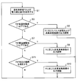
- FIG. 4 is a flowchart showing an embodiment of the output adjustment method of the pulse generator 100 according to the present invention. According to the flowchart shown in FIG. 4, the output of the pulse generation device of FIG. 1 is adjusted based on the measurement results (measured values) of the wattmeter side unit 160 and the temperature measurement unit 170.
- the predetermined temperature range 2 in which the pulse adjustment is performed is set to the low temperature side threshold T1 or less
- the predetermined temperature range 1 in which the output adjustment of the high frequency oscillator 110 is performed is set to the high temperature side threshold T2 or less.
- the predetermined temperature ranges 1 and 2 are equal to or lower than the low temperature side threshold T1.
- the pulse generation device 100 acquires the temperature measurement value T by the thermometer side unit 170 and the power measurement value P by the wattmeter side unit 160 (step S1).
- the measured temperature value T is equal to or lower than the low temperature side threshold value T1 (step S3, Y)
- the ambient temperature is low, and the high frequency pulse output increases beyond the legal regulation range as shown in FIG. Is in a state of being.
- the pulse adjustment described in FIGS. 2B and 2C and the output adjustment of the high-frequency oscillator 110 are used together to adjust the output of the high-frequency pulse (step S5).
- step S9 When the measured temperature value T exceeds the low temperature side threshold value T1 (step S3, N) and is lower than the high temperature side threshold value T2 that is higher than the low temperature side threshold value T1 (step S7, Y), it is shown in FIG. Thus, the output adjustment by the high frequency oscillator 110 is performed (step S9).
- the fluctuation amount X of the output of the high frequency pulse is determined according to the temperature measurement value T.
- the output fluctuation amount is the output fluctuation amount (difference) before and after adjustment.
- step S11 When the temperature measurement value T exceeds the high temperature side threshold value T2 (step S7, N) and the power measurement value P deviates from a predetermined power range (step S11, Y), as shown in FIG.
- the output is adjusted by 110 (step S13).
- step S11 when the power measurement value increases above the predetermined power range, output reduction adjustment is performed in step S13, and in step S11, when the power measurement value decreases below the predetermined power range, step In S13, output increase adjustment is performed.
- the fluctuation amount Y of the output of the high frequency pulse is determined according to the power measurement value P.
- the output of the high-frequency pulse varies (increases or decreases) by the output variation amount Y corresponding to the power measurement value P.
- step S11, N After performing the above steps S5, S9, and S13, or when the power measurement value P does not deviate from the predetermined power range (step S11, N), return to step S1 at a predetermined next timing and perform the same procedure. repeat.
- the predetermined next timing can be set as appropriate. For example, after a high-frequency pulse is output a predetermined number of times, or when mounted on a radar device, after the ranging of the radar device is completed. Can be set.
- the pulse adjustment shown in FIG. 2C is performed when the temperature measurement value T exceeds the low temperature side threshold value T1 and is lower than the high temperature side threshold value T2 that is higher than the low temperature side threshold value T1.
- the output adjustment of the high-frequency oscillator 110 shown in FIG. 2B may be performed when the temperature is equal to or lower than the low temperature side threshold value T1.
- pulse adjustment and output adjustment of the high-frequency oscillator 110 may be used in combination.
- FIG. 5 shows temperature characteristics of the output of the pulse generator 100 adjusted as the first embodiment based on the flowchart of FIG.
- the vertical axis represents the output (power) of the pulse generation device 100 at a predetermined measurement frequency
- the horizontal axis represents the temperature measurement value T acquired by the thermometer side unit 170.
- the output of the high-frequency pulse fluctuates linearly with respect to the change in the temperature measurement value T, and the output increases at a low temperature. For this reason, when the output adjustment is not performed, as shown by a one-dot chain line in the figure, it increases outside the legal regulation value or decreases outside the minimum output set value.
- the minimum output set value is set as appropriate from the detection limit of the receiving unit of the radar apparatus.
- step S5 is performed in a temperature range equal to or lower than the threshold value 1.
- the output fluctuation amount X1 corresponding to T1 varies.
- An example is shown.
- step S9 is performed in a temperature range exceeding the low temperature side threshold value T1 and not more than the high temperature side threshold value T2.
- the temperature measurement value T is equal to the high temperature side threshold value T2, it corresponds to T2.
- An example in which the output fluctuates by 2 is shown. Further, in FIG.
- step S ⁇ b> 13 is performed in a temperature range exceeding the high temperature side threshold T ⁇ b> 2, but in FIG. 5, there is an example in which the output fluctuates by the amount of fluctuation Y ⁇ b> 1 according to the power measurement value P acquired by the power measurement unit 160. It is shown.
- step S5 is performed when the temperature measurement value T is T1
- step S9 is performed at T2
- the fluctuation amount Y of the output of the high frequency pulse is realized by adjusting the output of the high frequency oscillator 110.
- the fluctuation amount of the output of the high frequency oscillator 110 is a measured power value. It is adjusted according to P. For example, the power threshold (upper limit or lower limit) determined as a predetermined power range is compared with the power measurement value P. If the difference is large, the fluctuation amount of the output of the high-frequency oscillator 110 is increased, and if the difference is small. The fluctuation amount of the output of the high frequency oscillator 110 is adjusted to be small.
- the fluctuation amount of the output of the high-frequency oscillator 110 performed at a time can be a fixed value, and the fluctuation amount of the output of the high-frequency oscillator 110 can be adjusted by adjusting the number of fluctuations of the output. That is, the number of output adjustments of one time or a plurality of times and the amount of fluctuation in output per time can be set in appropriate combination.
- the fluctuation amount X of the output of the high frequency pulse below the high temperature side threshold T2 (steps S5 and S9) is realized by the output adjustment and pulse adjustment of the high frequency oscillator 110, but here the fluctuation amount of the output of the high frequency oscillator 110 Is determined according to the temperature measurement value T.
- the amount of fluctuation in the output of the high-frequency oscillator 110 according to the temperature measurement value T can be set.
- the fluctuation amount of the output of the high frequency oscillator 110 adjusted according to the temperature measurement value T is set larger than the fluctuation amount of the output of the high frequency oscillator 110 adjusted according to the power measurement value P. Has been.
- the amount of fluctuation of the output of the high frequency oscillator 110 performed at a time can be increased, and the number of fluctuations of the output can be reduced. Since the number of output fluctuations can be reduced, the output of the pulse generation device 100 can be adjusted within a predetermined range with simpler control.
- FIG. 6 shows temperature characteristics of the output of the pulse generator 100 adjusted as the second embodiment based on the flowchart of FIG.
- the variation of the output is set to a plurality of times.
- the amount of fluctuation of the output per one time is made smaller than the amount of fluctuation of the output of the high-frequency oscillator 110 adjusted according to the power measurement value P.
- the number of output adjustments of the pulse generator 100 is larger than that in FIG.
- the amount of fluctuation is small.
- output adjustments of the output fluctuation amounts X2, X3, and X4 are performed three times in total, and the range in which the vertical axis output changes in X2, X3, and X4 is narrower than Y1.
- the output can be adjusted within a relatively high level range, so that the detection capability of the radar device when mounted on the radar device. Can be maintained at a high level.
- the number of output adjustments is increased only in a temperature range that exceeds the low temperature side threshold value T ⁇ b> 1 and is equal to or lower than the high temperature side threshold value T ⁇ b> 2.
- the number of output adjustments can be set as appropriate. That is, the number of output adjustments of one time or a plurality of times and the fluctuation amount of the output per time can be set in combination as appropriate, and the output of the pulse generation device 100 can be adjusted within a predetermined range.
- the pulse generation device 100 and the output adjustment method of the pulse generation device 100 according to the present invention when an ambient temperature change or aging deterioration occurs, the power measurement unit 160 and the thermometer side unit 170 are measured.
- the output of the high frequency pulse can be adjusted within a predetermined range. 5 and 6, in the temperature range exceeding the high temperature side threshold value T2, the output of the high frequency pulse can be adjusted by adjusting the output of the high frequency oscillator 110 according to the measurement result of the wattmeter side unit 160.
- the output of the high frequency pulse can be adjusted by adjusting the output of the high frequency oscillator 110 in accordance with the measurement result of the thermometer side unit 170.
- the output of the high frequency pulse in the temperature range equal to or lower than the low temperature side threshold T1, the output of the high frequency pulse can be adjusted by adjusting the output of the high frequency oscillator 110 and adjusting the pulse according to the measurement result of the thermometer side unit 170.
- the pulse generator 100 stores the temperature characteristics of the high-frequency oscillator 110 and the modulator 140 acquired in advance, and the fluctuation amount of the output of the high-frequency oscillator 110 determined according to the temperature measurement value T and the power measurement value P. It is also possible to include a calculation processing unit that calculates the above as needed. In the above embodiments and examples, the example in which the upper limit of the adjustment range of the output of the pulse generation device 100 is set as the legal regulation value has been shown. The output of the apparatus 100 may be adjusted.
- Pulse generator 110 High frequency oscillator 120 Baseband pulse generation part 121 Pulse generator 122 Low pass filter 123 Pulse pattern memory 130 Timing generator 140 Modulator 150 Output variable device 160 Electric power measurement part 170 Thermometer side part
Landscapes
- Engineering & Computer Science (AREA)
- Radar, Positioning & Navigation (AREA)
- Remote Sensing (AREA)
- Physics & Mathematics (AREA)
- Computer Networks & Wireless Communication (AREA)
- General Physics & Mathematics (AREA)
- Electromagnetism (AREA)
- Radar Systems Or Details Thereof (AREA)
Abstract
Priority Applications (4)
| Application Number | Priority Date | Filing Date | Title |
|---|---|---|---|
| CN201780050712.6A CN109642939B (zh) | 2016-12-22 | 2017-12-20 | 脉冲生成装置及其输出调整方法 |
| JP2018558033A JP7195704B2 (ja) | 2016-12-22 | 2017-12-20 | パルス生成装置、およびその出力調整方法 |
| EP17883437.0A EP3561538B1 (fr) | 2016-12-22 | 2017-12-20 | Dispositif de génération d'impulsions et procédé de réglage de sortie correspondant |
| US16/437,523 US11187781B2 (en) | 2016-12-22 | 2019-06-11 | Pulse generating device and output adjustment method thereof |
Applications Claiming Priority (2)
| Application Number | Priority Date | Filing Date | Title |
|---|---|---|---|
| JP2016249247 | 2016-12-22 | ||
| JP2016-249247 | 2016-12-22 |
Related Child Applications (1)
| Application Number | Title | Priority Date | Filing Date |
|---|---|---|---|
| US16/437,523 Continuation US11187781B2 (en) | 2016-12-22 | 2019-06-11 | Pulse generating device and output adjustment method thereof |
Publications (1)
| Publication Number | Publication Date |
|---|---|
| WO2018117155A1 true WO2018117155A1 (fr) | 2018-06-28 |
Family
ID=62626441
Family Applications (1)
| Application Number | Title | Priority Date | Filing Date |
|---|---|---|---|
| PCT/JP2017/045737 Ceased WO2018117155A1 (fr) | 2016-12-22 | 2017-12-20 | Dispositif de génération d'impulsions et procédé de réglage de sortie correspondant |
Country Status (5)
| Country | Link |
|---|---|
| US (1) | US11187781B2 (fr) |
| EP (1) | EP3561538B1 (fr) |
| JP (1) | JP7195704B2 (fr) |
| CN (1) | CN109642939B (fr) |
| WO (1) | WO2018117155A1 (fr) |
Families Citing this family (3)
| Publication number | Priority date | Publication date | Assignee | Title |
|---|---|---|---|---|
| CN110618411B (zh) * | 2019-10-23 | 2022-11-04 | 电子科技大学 | 一种机载雷达杂波实时信号产生方法 |
| DE102019133245B4 (de) * | 2019-12-05 | 2021-06-24 | Endress+Hauser SE+Co. KG | Füllstandsmessgerät und Verfahren zur Radar-basierten Messung eines Füllstands |
| US20220130369A1 (en) * | 2020-10-28 | 2022-04-28 | Gulfstream Aerospace Corporation | Quiet flight deck communication using ultrasonic phased array |
Citations (4)
| Publication number | Priority date | Publication date | Assignee | Title |
|---|---|---|---|---|
| US20050259000A1 (en) * | 2004-05-18 | 2005-11-24 | Roke Manor Research Limited | Apparatus for producing an amplified radio frequency pulse |
| JP2014209110A (ja) * | 2013-03-29 | 2014-11-06 | 古河電気工業株式会社 | 送受信装置 |
| JP5697066B1 (ja) | 2013-03-29 | 2015-04-08 | 古河電気工業株式会社 | パルス生成装置 |
| JP2016156732A (ja) * | 2015-02-25 | 2016-09-01 | 株式会社東芝 | 距離測定装置及び距離測定方法 |
Family Cites Families (22)
| Publication number | Priority date | Publication date | Assignee | Title |
|---|---|---|---|---|
| US4931976A (en) * | 1988-11-03 | 1990-06-05 | Tideland Signal Corporation | Temperature compensated side lobe suppression |
| JP2611519B2 (ja) * | 1989-09-11 | 1997-05-21 | 日本電気株式会社 | フェーズドアレイ空中線の性能補償装置 |
| JP3023172B2 (ja) * | 1991-03-08 | 2000-03-21 | インターナショナル・スタンダード・エレクトリック・コーポレイション | 誤差補正を備えたtrモジュール |
| US5381444A (en) * | 1991-10-31 | 1995-01-10 | Fujitsu Limited | Radio environment measuring system |
| JPH1164488A (ja) * | 1997-08-20 | 1999-03-05 | Mitsubishi Electric Corp | レーダ装置 |
| JP2003018009A (ja) * | 2001-06-29 | 2003-01-17 | Mitsubishi Electric Corp | デジタルアナログコンバータ |
| JP4282429B2 (ja) | 2003-10-02 | 2009-06-24 | 株式会社東芝 | アクティブフェーズドアレイアンテナ装置 |
| US20050249667A1 (en) * | 2004-03-24 | 2005-11-10 | Tuszynski Jack A | Process for treating a biological organism |
| JP2006197242A (ja) | 2005-01-13 | 2006-07-27 | Toshiba Corp | 送信装置 |
| US20080246650A1 (en) * | 2005-01-28 | 2008-10-09 | Tasuku Teshirogi | Short Range Radar and Method of Controlling the Same |
| EP1843170A1 (fr) * | 2005-01-28 | 2007-10-10 | Anritsu Corporation | Radar ulb a impulsions courtes |
| US20070194978A1 (en) * | 2006-01-27 | 2007-08-23 | Tasuku Teshirogi | Uwb short-range radar |
| JPWO2007122873A1 (ja) * | 2006-04-20 | 2009-09-03 | アンリツ株式会社 | 短パルスレーダ及びその制御方法 |
| JP2009085922A (ja) | 2007-10-03 | 2009-04-23 | Japan Radio Co Ltd | スペクトラムモニタ付きレーダ装置 |
| JP4755657B2 (ja) | 2008-01-18 | 2011-08-24 | 三菱電機株式会社 | ミリ波送受信モジュール |
| JP2011094997A (ja) * | 2009-10-27 | 2011-05-12 | Alps Electric Co Ltd | 無線センサ装置 |
| JP5404442B2 (ja) * | 2010-01-18 | 2014-01-29 | 株式会社東芝 | 安全入力装置 |
| JP5810287B2 (ja) * | 2010-07-29 | 2015-11-11 | パナソニックIpマネジメント株式会社 | レーダ装置 |
| JP5760697B2 (ja) | 2010-10-27 | 2015-08-12 | 日本電波工業株式会社 | 信号レベル調整装置及び高周波機器 |
| JP5889037B2 (ja) * | 2012-02-22 | 2016-03-22 | 古河電気工業株式会社 | パルスレーダ装置 |
| WO2014018798A2 (fr) * | 2012-07-25 | 2014-01-30 | Nxstage Medical, Inc. | Dispositifs, procédés et systèmes de mesure de propriété de fluide |
| WO2014045928A1 (fr) * | 2012-09-19 | 2014-03-27 | 古野電気株式会社 | Radar à compression d'impulsion |
-
2017
- 2017-12-20 WO PCT/JP2017/045737 patent/WO2018117155A1/fr not_active Ceased
- 2017-12-20 CN CN201780050712.6A patent/CN109642939B/zh active Active
- 2017-12-20 JP JP2018558033A patent/JP7195704B2/ja active Active
- 2017-12-20 EP EP17883437.0A patent/EP3561538B1/fr active Active
-
2019
- 2019-06-11 US US16/437,523 patent/US11187781B2/en active Active
Patent Citations (4)
| Publication number | Priority date | Publication date | Assignee | Title |
|---|---|---|---|---|
| US20050259000A1 (en) * | 2004-05-18 | 2005-11-24 | Roke Manor Research Limited | Apparatus for producing an amplified radio frequency pulse |
| JP2014209110A (ja) * | 2013-03-29 | 2014-11-06 | 古河電気工業株式会社 | 送受信装置 |
| JP5697066B1 (ja) | 2013-03-29 | 2015-04-08 | 古河電気工業株式会社 | パルス生成装置 |
| JP2016156732A (ja) * | 2015-02-25 | 2016-09-01 | 株式会社東芝 | 距離測定装置及び距離測定方法 |
Non-Patent Citations (1)
| Title |
|---|
| See also references of EP3561538A4 |
Also Published As
| Publication number | Publication date |
|---|---|
| JP7195704B2 (ja) | 2022-12-26 |
| CN109642939A (zh) | 2019-04-16 |
| US20190293754A1 (en) | 2019-09-26 |
| JPWO2018117155A1 (ja) | 2019-12-19 |
| EP3561538B1 (fr) | 2025-11-12 |
| CN109642939B (zh) | 2023-05-12 |
| EP3561538A4 (fr) | 2020-06-10 |
| EP3561538A1 (fr) | 2019-10-30 |
| US11187781B2 (en) | 2021-11-30 |
Similar Documents
| Publication | Publication Date | Title |
|---|---|---|
| CN110366689B (zh) | 雷达装置 | |
| US7675459B2 (en) | Equivalent time sampling radar | |
| US11422230B2 (en) | System and method for receiving a radar signal | |
| JP6994371B2 (ja) | レーダ装置 | |
| JP5849245B2 (ja) | レーダ装置 | |
| US11187781B2 (en) | Pulse generating device and output adjustment method thereof | |
| US10505770B2 (en) | Reception signal processing device, radar, and object detection method | |
| CN109863419B (zh) | 雷达装置以及电波干扰的回避方法 | |
| JP5697066B1 (ja) | パルス生成装置 | |
| WO2016084468A1 (fr) | Dispositif de radar, système de réglage de sortie de radar, et procédé de réglage de sortie de radar | |
| US6646592B2 (en) | Pulse radar device | |
| US20080024358A1 (en) | Radar system | |
| CN111602067B (zh) | 雷达装置和记录有异常判定程序的计算机能读取的记录介质 | |
| JP6452300B2 (ja) | 送受信装置 | |
| EP1736795A1 (fr) | Radar a impulsions courtes et procede de controle associe | |
| JP2021139694A (ja) | レーダ装置及びレーダ装置の制御方法 | |
| JP2006242818A (ja) | Fm−cwレーダ装置および同装置のノイズ抑制方法 | |
| KR101359344B1 (ko) | Fmcw 기반 거리 측정 장치 | |
| JP5150113B2 (ja) | レーダ装置 | |
| JP2016003870A (ja) | 距離測定装置 | |
| US20250067863A1 (en) | Range finding device | |
| JP2019144082A (ja) | Fmcwレーダ装置 | |
| JP5019994B2 (ja) | 等価時間サンプルレーダ装置 | |
| JP2015052515A (ja) | レーダ装置及びパルス送受信方法 |
Legal Events
| Date | Code | Title | Description |
|---|---|---|---|
| 121 | Ep: the epo has been informed by wipo that ep was designated in this application |
Ref document number: 17883437 Country of ref document: EP Kind code of ref document: A1 |
|
| ENP | Entry into the national phase |
Ref document number: 2018558033 Country of ref document: JP Kind code of ref document: A |
|
| NENP | Non-entry into the national phase |
Ref country code: DE |
|
| ENP | Entry into the national phase |
Ref document number: 2017883437 Country of ref document: EP Effective date: 20190722 |
|
| WWG | Wipo information: grant in national office |
Ref document number: 2017883437 Country of ref document: EP |