EP4071025B1 - Procédé de commande de véhicule et dispositif de commande de véhicule - Google Patents
Procédé de commande de véhicule et dispositif de commande de véhicule Download PDFInfo
- Publication number
- EP4071025B1 EP4071025B1 EP19955270.4A EP19955270A EP4071025B1 EP 4071025 B1 EP4071025 B1 EP 4071025B1 EP 19955270 A EP19955270 A EP 19955270A EP 4071025 B1 EP4071025 B1 EP 4071025B1
- Authority
- EP
- European Patent Office
- Prior art keywords
- vehicle
- velocity
- host vehicle
- oncoming
- oncoming vehicle
- Prior art date
- Legal status (The legal status is an assumption and is not a legal conclusion. Google has not performed a legal analysis and makes no representation as to the accuracy of the status listed.)
- Active
Links
Images





Classifications
-
- B—PERFORMING OPERATIONS; TRANSPORTING
- B60—VEHICLES IN GENERAL
- B60W—CONJOINT CONTROL OF VEHICLE SUB-UNITS OF DIFFERENT TYPE OR DIFFERENT FUNCTION; CONTROL SYSTEMS SPECIALLY ADAPTED FOR HYBRID VEHICLES; ROAD VEHICLE DRIVE CONTROL SYSTEMS FOR PURPOSES NOT RELATED TO THE CONTROL OF A PARTICULAR SUB-UNIT
- B60W30/00—Purposes of road vehicle drive control systems not related to the control of a particular sub-unit, e.g. of systems using conjoint control of vehicle sub-units
- B60W30/14—Adaptive cruise control
- B60W30/143—Speed control
-
- B—PERFORMING OPERATIONS; TRANSPORTING
- B60—VEHICLES IN GENERAL
- B60W—CONJOINT CONTROL OF VEHICLE SUB-UNITS OF DIFFERENT TYPE OR DIFFERENT FUNCTION; CONTROL SYSTEMS SPECIALLY ADAPTED FOR HYBRID VEHICLES; ROAD VEHICLE DRIVE CONTROL SYSTEMS FOR PURPOSES NOT RELATED TO THE CONTROL OF A PARTICULAR SUB-UNIT
- B60W30/00—Purposes of road vehicle drive control systems not related to the control of a particular sub-unit, e.g. of systems using conjoint control of vehicle sub-units
- B60W30/08—Active safety systems predicting or avoiding probable or impending collision or attempting to minimise its consequences
- B60W30/09—Taking automatic action to avoid collision, e.g. braking and steering
-
- B—PERFORMING OPERATIONS; TRANSPORTING
- B60—VEHICLES IN GENERAL
- B60W—CONJOINT CONTROL OF VEHICLE SUB-UNITS OF DIFFERENT TYPE OR DIFFERENT FUNCTION; CONTROL SYSTEMS SPECIALLY ADAPTED FOR HYBRID VEHICLES; ROAD VEHICLE DRIVE CONTROL SYSTEMS FOR PURPOSES NOT RELATED TO THE CONTROL OF A PARTICULAR SUB-UNIT
- B60W30/00—Purposes of road vehicle drive control systems not related to the control of a particular sub-unit, e.g. of systems using conjoint control of vehicle sub-units
- B60W30/08—Active safety systems predicting or avoiding probable or impending collision or attempting to minimise its consequences
- B60W30/095—Predicting travel path or likelihood of collision
-
- B—PERFORMING OPERATIONS; TRANSPORTING
- B60—VEHICLES IN GENERAL
- B60W—CONJOINT CONTROL OF VEHICLE SUB-UNITS OF DIFFERENT TYPE OR DIFFERENT FUNCTION; CONTROL SYSTEMS SPECIALLY ADAPTED FOR HYBRID VEHICLES; ROAD VEHICLE DRIVE CONTROL SYSTEMS FOR PURPOSES NOT RELATED TO THE CONTROL OF A PARTICULAR SUB-UNIT
- B60W30/00—Purposes of road vehicle drive control systems not related to the control of a particular sub-unit, e.g. of systems using conjoint control of vehicle sub-units
- B60W30/18—Propelling the vehicle
- B60W30/18009—Propelling the vehicle related to particular drive situations
- B60W30/18163—Lane change; Overtaking manoeuvres
-
- B—PERFORMING OPERATIONS; TRANSPORTING
- B60—VEHICLES IN GENERAL
- B60W—CONJOINT CONTROL OF VEHICLE SUB-UNITS OF DIFFERENT TYPE OR DIFFERENT FUNCTION; CONTROL SYSTEMS SPECIALLY ADAPTED FOR HYBRID VEHICLES; ROAD VEHICLE DRIVE CONTROL SYSTEMS FOR PURPOSES NOT RELATED TO THE CONTROL OF A PARTICULAR SUB-UNIT
- B60W40/00—Estimation or calculation of non-directly measurable driving parameters for road vehicle drive control systems not related to the control of a particular sub unit, e.g. by using mathematical models
- B60W40/02—Estimation or calculation of non-directly measurable driving parameters for road vehicle drive control systems not related to the control of a particular sub unit, e.g. by using mathematical models related to ambient conditions
- B60W40/04—Traffic conditions
-
- B—PERFORMING OPERATIONS; TRANSPORTING
- B60—VEHICLES IN GENERAL
- B60W—CONJOINT CONTROL OF VEHICLE SUB-UNITS OF DIFFERENT TYPE OR DIFFERENT FUNCTION; CONTROL SYSTEMS SPECIALLY ADAPTED FOR HYBRID VEHICLES; ROAD VEHICLE DRIVE CONTROL SYSTEMS FOR PURPOSES NOT RELATED TO THE CONTROL OF A PARTICULAR SUB-UNIT
- B60W2520/00—Input parameters relating to overall vehicle dynamics
-
- B—PERFORMING OPERATIONS; TRANSPORTING
- B60—VEHICLES IN GENERAL
- B60W—CONJOINT CONTROL OF VEHICLE SUB-UNITS OF DIFFERENT TYPE OR DIFFERENT FUNCTION; CONTROL SYSTEMS SPECIALLY ADAPTED FOR HYBRID VEHICLES; ROAD VEHICLE DRIVE CONTROL SYSTEMS FOR PURPOSES NOT RELATED TO THE CONTROL OF A PARTICULAR SUB-UNIT
- B60W2520/00—Input parameters relating to overall vehicle dynamics
- B60W2520/10—Longitudinal speed
-
- B—PERFORMING OPERATIONS; TRANSPORTING
- B60—VEHICLES IN GENERAL
- B60W—CONJOINT CONTROL OF VEHICLE SUB-UNITS OF DIFFERENT TYPE OR DIFFERENT FUNCTION; CONTROL SYSTEMS SPECIALLY ADAPTED FOR HYBRID VEHICLES; ROAD VEHICLE DRIVE CONTROL SYSTEMS FOR PURPOSES NOT RELATED TO THE CONTROL OF A PARTICULAR SUB-UNIT
- B60W2554/00—Input parameters relating to objects
- B60W2554/20—Static objects
-
- B—PERFORMING OPERATIONS; TRANSPORTING
- B60—VEHICLES IN GENERAL
- B60W—CONJOINT CONTROL OF VEHICLE SUB-UNITS OF DIFFERENT TYPE OR DIFFERENT FUNCTION; CONTROL SYSTEMS SPECIALLY ADAPTED FOR HYBRID VEHICLES; ROAD VEHICLE DRIVE CONTROL SYSTEMS FOR PURPOSES NOT RELATED TO THE CONTROL OF A PARTICULAR SUB-UNIT
- B60W2554/00—Input parameters relating to objects
- B60W2554/40—Dynamic objects, e.g. animals, windblown objects
- B60W2554/404—Characteristics
- B60W2554/4041—Position
-
- B—PERFORMING OPERATIONS; TRANSPORTING
- B60—VEHICLES IN GENERAL
- B60W—CONJOINT CONTROL OF VEHICLE SUB-UNITS OF DIFFERENT TYPE OR DIFFERENT FUNCTION; CONTROL SYSTEMS SPECIALLY ADAPTED FOR HYBRID VEHICLES; ROAD VEHICLE DRIVE CONTROL SYSTEMS FOR PURPOSES NOT RELATED TO THE CONTROL OF A PARTICULAR SUB-UNIT
- B60W2554/00—Input parameters relating to objects
- B60W2554/40—Dynamic objects, e.g. animals, windblown objects
- B60W2554/404—Characteristics
- B60W2554/4042—Longitudinal speed
-
- B—PERFORMING OPERATIONS; TRANSPORTING
- B60—VEHICLES IN GENERAL
- B60W—CONJOINT CONTROL OF VEHICLE SUB-UNITS OF DIFFERENT TYPE OR DIFFERENT FUNCTION; CONTROL SYSTEMS SPECIALLY ADAPTED FOR HYBRID VEHICLES; ROAD VEHICLE DRIVE CONTROL SYSTEMS FOR PURPOSES NOT RELATED TO THE CONTROL OF A PARTICULAR SUB-UNIT
- B60W2554/00—Input parameters relating to objects
- B60W2554/40—Dynamic objects, e.g. animals, windblown objects
- B60W2554/404—Characteristics
- B60W2554/4044—Direction of movement, e.g. backwards
Definitions
- the present invention relates to a vehicle control method and a vehicle control device.
- Patent Literature 1 A drive assistance device is known that avoids an encounter with an oncoming vehicle when there is a probability that the oncoming vehicle could project from the oncoming lane toward the own lane (Patent Literature 1).
- the invention disclosed in Patent Literature 1 determines whether a passing route of the oncoming vehicle overlaps with the own lane in accordance with a distance between a parked vehicle in the oncoming lane and the center line of the road.
- the invention disclosed in Patent Literature 1 causes the host vehicle to stop or decelerate when the passing route of the oncoming vehicle is determined to overlap with the own lane.
- Patent Literature 2 describes a vehicle control method and device for avoiding an oncoming vehicle in an adjacent lane of a host vehicle when there is an obstacle in the own lane of the host vehicle.
- a passing position at which the host vehicle passes the moving object is calculated and when the passing position is in a preset area around the stationary object, the host vehicle is decelerated or accelerated to move the passing position out of the area, depending on whether the calculated passing position is closer to the host vehicle or to the oncoming vehicle than a center of the preset area.
- Patent Literature 3 describes a method for taking into account stationary objects to be avoided in passing ongoing traffic by setting respective areas in which a passing is not possible.
- Patent Literature 4 describes a method and device for vehicle control that is capable of stopping a host vehicle before reaching a construction area in order to avoid passing ongoing traffic in the construction area.
- Patent Literature 1 does not take account of the intention of the driver of the oncoming vehicle and thus could cause the host vehicle to decelerate or stop unnecessarily even when the host vehicle and the oncoming vehicle can pass each other without close encounter. Even with taking into account the teachings of Patent Literature 2 to Patent Literature 4, there is room for further improvement.
- the present invention provides a an improved vehicle control method and a vehicle control device configured to take account of an intention of a driver of an oncoming vehicle.
- the present invention takes account of the intention of the driver of the oncoming vehicle, so as to avoid sudden braking or unnecessary acceleration or deceleration.
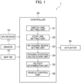
- the vehicle control device 1 includes a GPS receiver 10, a sensor 11, a map database 12, a controller 20, and several kinds of actuators 30.
- the vehicle control device 1 may be mounted on either a vehicle equipped with an automated driving function or a vehicle without equipped with an automated driving function.
- the vehicle control device 1 may be mounted on a vehicle capable of switching between automated driving and manual driving.
- automated driving refers to a state in which at least any of actuators such as a brake, an accelerator, and a steering wheel is controlled without the intervention of the occupant.
- the automated driving thus can include a state in which other actuators are operated by the occupant.
- the automated driving also refers to a state in which any control such as acceleration/deceleration control and lateral positioning control only needs to be executed.
- the term “manual driving” as used in the first embodiment refers to a state in which the occupant operates the brake, the accelerator, and the steering wheel, for example.
- the GPS receiver 10 receives radio waves from an artificial satellite so as to detect positional information of the host vehicle on the ground.
- the positional information of the host vehicle detected by the GPS receiver 10 includes the information on latitude and the information on longitude.
- the GPS receiver 10 outputs the detected positional information of the host vehicle to the controller 20.
- the way of detecting the positional information of the host vehicle is not limited to the GPS receiver 10.
- odometry may be used to estimate the position of the host vehicle. Odometry is a way of obtaining a moving amount and an advancing direction of a vehicle in accordance with a rotation angle and an angular velocity of the vehicle so as to estimate the position of the vehicle.
- the sensor 11 is a device mounted on the host vehicle to detect objects around the host vehicle.
- the sensor 11 includes several kinds of sensors such as a camera, lidar, a radar, a millimeter-wave radar, a laser rangefinder, and a sonar.
- the sensor 11 detects, as objects around the host vehicle, moving objects including other vehicles, motorcycles, bicycles, and pedestrians, and stationary objects including obstacles, fallen objects, and parked vehicles.
- the sensor 11 also detects a position, an attitude (a yaw angle), a size, a velocity, an acceleration rate, a deceleration rate, and a yaw rate of the respective moving objects and stationary objects with respect to the host vehicle.
- the sensor 11 may also include other sensors such as a wheel speed sensor (a second sensor), a steering angle sensor, and a gyro sensor.
- the wheel speed sensor detects a speed of rotation of the wheels of the host vehicle. Detecting the speed of rotation can obtain a velocity of the host vehicle.
- the sensor 11 outputs the detected information to the controller 20.
- the map database 12 is a database stored in a car navigation device, for example, and includes map information such as road information and facility information necessary for route guidance.
- the road information refers to information on the number of lanes on a road, road boundary lines, and a relation of connection of lanes.
- the map database 12 outputs the map information to the controller 20 in response to the request from the controller 20. While the first embodiment is illustrated with the case in which the vehicle control device 1 includes the map database 12, the vehicle control device 1 does not necessarily include the map database 12.
- the map information may be acquired by the sensor 11, or may be acquired through vehicle-to-vehicle communications or road-to-vehicle communications. When the map information is stored in a server externally installed, the vehicle control device 1 may acquire the map information from the server through communications as necessary. The vehicle control device 1 may regularly acquire the latest map information from the server so as to update the stored map information.
- the controller 20 is a general-purpose microcomputer including a central processing unit (CPU), a memory, and an input-output unit.
- a computer program is installed on the microcomputer so as to function as the vehicle control device 1.
- the microcomputer functions as a plurality of information processing circuits included in the vehicle control device 1 when the computer program is executed. While the present embodiment is illustrated with the case in which the software is installed to fabricate the respective information processing circuits included in the vehicle control device 1, dedicated hardware for executing each information processing as described below can be prepared to compose the information processing circuits.
- the respective information processing circuits may be composed of individual hardware.
- the controller 20 includes, as examples of the plural information processing circuits, a switch line setting unit 21, a stop line setting unit 22, a no-passing region setting unit 23, a passing position calculation unit 24, a velocity determination unit 25, and a vehicle control unit 26.
- the switch line setting unit 21 integrates the positional information of the host vehicle output from the GPS receiver 10 and the position of the moving object or the stationary object output from the sensor 11 with the map information output from the map database 12, and generates map information including the position of the host vehicle and the position of the moving object or the stationary object.
- the switch line setting unit 21 sets a virtual switch line on the map extending in the lane width direction in the oncoming lane adjacent to the traveling lane in which the host vehicle is traveling. For example, when a parked vehicle is detected in the oncoming lane, the switch line setting unit 21 sets the switch line on the map in the oncoming lane at a position distant from the parked vehicle by a predetermined distance in the traveling direction of the host vehicle.
- position refers to a position on the map unless otherwise specified.
- the stop line setting unit 22 sets a virtual stop line extending in the lane width direction in the traveling lane in which the host vehicle is traveling. For example, when a parked vehicle is detected in the oncoming lane, the stop line setting unit 22 sets the stop line in the traveling lane at a position distant from the parked vehicle by a predetermined distance in the traveling direction of an oncoming vehicle.
- the oncoming vehicle is a vehicle traveling in the oncoming lane.
- the stop line is set at a position at which the host vehicle can stop at a predetermined deceleration rate after starting decelerating from the current position.
- the stop line is also set at a position at which the host vehicle can avoid a collision with the oncoming vehicle that is traveling in the oncoming lane and could project to the traveling lane so as to avoid the parked vehicle.
- the predetermined distance used for setting the switch line may be the same as or different from the predetermined distance used for setting the stop line.
- the no-passing region setting unit 23 sets a no-passing region in accordance with the switch line and the stop line set by the switch line setting unit 21 and the stop line setting unit 22.
- the no-passing region setting unit 23 sets, as the no-passing region, a region including the switch line and the stop line on the road defined between the switch line and the stop line.
- the no-passing region is set on the road around the parked vehicle.
- the first embodiment sets the no-passing region as a region in which the host vehicle is prohibited from passing the oncoming vehicle.
- the passing position calculation unit 24 determines whether the position at which the host vehicle and the oncoming vehicle pass each other is present within the no-passing region set by the no-passing region setting unit 23. In particular, the passing position calculation unit 24 calculates the passing position at which the host vehicle passes the oncoming vehicle in accordance with a relative distance between the host vehicle and the oncoming vehicle, a velocity of the host vehicle, and a velocity of the oncoming vehicle. The passing position calculation unit 24 then determines whether the calculated passing position is present within the no-passing region. The relative distance between the host vehicle and the oncoming vehicle, the velocity of the host vehicle, and the velocity of the oncoming vehicle are detected by the sensor 11.
- the velocity determination unit 25 estimates an intention of the driver of the oncoming vehicle when the oncoming vehicle is manual driving or estimates an action expected by a driving control device of the oncoming vehicle when the oncoming vehicle is automated driving (collectively referred to below as an "intention of the oncoming vehicle") so as to determines a velocity of the host vehicle.
- an intention of the oncoming vehicle is described in detail below.
- the vehicle control unit 26 controls the respective actuators 30 so as to cause the host vehicle to travel at the velocity determined by the velocity determination unit 25.
- the actuators 30 include a brake actuator, an accelerator pedal actuator, and a steering actuator.
- Fig. 2 illustrates a road with one lane in each direction.
- Fig. 2 illustrates the case in which the host vehicle 50 is traveling toward the left, and the oncoming vehicle 51 is traveling toward the right.
- the traveling direction of the host vehicle 50 is opposite to the traveling direction of the oncoming vehicle 51.
- the lane in which the host vehicle 50 is traveling is herein referred to as a traveling lane, and the lane in which the oncoming vehicle 51 is herein traveling is referred to as an oncoming lane.
- the oncoming lane is located next to the traveling lane.
- the parked vehicle 52 and the oncoming vehicle 51 are presumed to be detected by the sensor 11.
- the positional information and velocity of the parked vehicle 52 and the positional information and velocity of the oncoming vehicle 51 are presumed to be detected by the sensor 11.
- the positional information of the parked vehicle 52 and the positional information of the oncoming vehicle 51 are detected by a laser rangefinder (a first sensor, a third sensor).
- the laser rangefinder emits radio waves to scan the objects (the parked vehicle 52 and the oncoming vehicle 51 in this case), and measures the reflected radio waves so as to acquire the distance and the direction to the respective objects.
- the position of the parked vehicle 52 and the position of the oncoming vehicle 51 may each be detected as a relative position with respect to the position of the host vehicle 50 or detected as a position on the coordinates based on the position of the host vehicle 50 as the origin.
- the velocity of the parked vehicle 52 and the velocity of the oncoming vehicle 51 are detected by a camera (a fourth sensor), for example.
- a difference between a current image captured by the camera and an image of the immediately previous frame is extracted, so as to acquire the velocity of the parked vehicle 52 and the velocity of the oncoming vehicle 51.
- a frame rate of the camera can be, but not necessarily, set to either 30 frames per second (fps) or 60 fps.
- the parked vehicle 52 in the first embodiment is determined to be a stationary object, since the velocity of the parked vehicle 52 is detected to be zero. Namely, the object detected around the host vehicle 50 is determined to be a stationary object when the velocity of the object is zero or is a quite low velocity so as to be presumed to be approximately zero.
- the switch line setting unit 21 sets a virtual switch line 60 extending in the lane width direction in the oncoming lane at a position distant from the parked vehicle 52 by a predetermined distance in the traveling direction of the host vehicle 50.
- the stop line setting unit 22 sets a virtual stop line 61 extending in the lane width direction in the traveling lane at a position distant from the parked vehicle 52 by a predetermined distance in the traveling direction of the oncoming vehicle 51.
- the no-passing region setting unit 23 sets a no-passing region R including the switch line 60 and the stop line 61 on the road defined in a region between the switch line 60 and the stop line 61.
- the no-passing region R is a region including the switch line 60 and the stop line 61 and defined by the switch line 60 and the stop line 61 on the road.
- the shape of the no-passing region R can be determined as appropriate, and may be rectangular, for example.
- the reason for setting the no-passing region R is to prevent a collision between the oncoming vehicle 51 and the host vehicle 50 when the oncoming vehicle 51 passes the host vehicle 50 while avoiding the parked vehicle 52.
- the parked vehicle 52 in this case is thus present in the no-passing region R.
- the passing position calculation unit 24 determines whether the position at which the host vehicle 50 and the oncoming vehicle 51 pass each other is present within the no-passing region R. In particular, as illustrated in Fig. 2 , the passing position calculation unit 24 calculates a position P1 at which the host vehicle 50 and the oncoming vehicle 51 pass each other in accordance with a relative distance L between the host vehicle 50 and the oncoming vehicle 51 (a distance from the position of the host vehicle 50 when defined as the origin), a velocity V1 of the host vehicle 50, and a velocity V2 of the oncoming vehicle 51.
- the passing position calculation unit 24 determines whether the calculated passing position P1 is present within the no-passing region R.
- Fig. 2 illustrates the case in which the passing position P1 is present within the no-passing region R.
- the velocity determination unit 25 estimates an intention of the driver of the oncoming vehicle 51 so as to determine a velocity of the host vehicle 50.
- the intention of the driver of the oncoming vehicle 51 is whether the oncoming vehicle 51 waits for the host vehicle 50 to pass the parked vehicle 52 or not.
- the reason for estimating the intention of the driver of the oncoming vehicle 51 is that the host vehicle 50 can avoid sudden braking or unnecessary acceleration or deceleration when the velocity of the host vehicle 50 is determined in accordance with the estimation of the intention of the driver of the oncoming vehicle 51. For example, when the intention of the driver of the oncoming vehicle 51 is to wait for the host vehicle 50 to pass, the host vehicle 50 can be led to keep the velocity or accelerate so as to pass the parked vehicle 52.
- the host vehicle 50 can be led to decelerate so as to smoothly stop at a position (on the outside of the no-passing region R) at which the host vehicle 50 can prevent a collision with the oncoming vehicle 51 that could project toward the traveling lane so as to avoid the parked vehicle 52.
- the host vehicle 50 may be caused to make sudden braking or unnecessary acceleration or deceleration. For example, when a blocked area caused by the parked vehicle 52 is large, or when there is a pedestrian crossing around the parked vehicle 52, the oncoming vehicle 51 would accelerate to pass by the parked vehicle 52 after briefly decelerating or making a stop for safety. In such a case, the host vehicle 50 first starts accelerating, since the passing position P1 is temporarily shifted toward the oncoming vehicle 51 due to the deceleration of the oncoming vehicle 51. The host vehicle 50, however, soon needs to decelerate because the oncoming vehicle 51 again accelerates and the passing position P1 is then shifted toward the host vehicle 50.
- the acceleration/deceleration control for the host vehicle 50 is inevitably switched if the intention of the driver of the oncoming vehicle 51 is not estimated, which may cause the host vehicle 50 to make sudden braking or unnecessary acceleration or deceleration.
- the first embodiment estimates the intention of the driver of the oncoming vehicle 51 to determine the velocity of the host vehicle 50, so as to avoid sudden braking or unnecessary acceleration or deceleration.
- the velocity determination unit 25 estimates that the intention of the driver of the oncoming vehicle 51 is to pass by the parked vehicle 52 without waiting for the host vehicle 50.
- the velocity determination unit 25 in this case determines the deceleration rate of the host vehicle 50 so as to smoothly stop at the stop line 61 in order to avoid a collision between the oncoming vehicle 51 and the host vehicle 50.
- the velocity determination unit 25 estimates that the intention of the driver of the oncoming vehicle 51 is to wait for the host vehicle 50 to pass the parked vehicle 52.
- the velocity determination unit 25 in this case determines to cause the host vehicle 50 to keep the current velocity or accelerate so as to lead the host vehicle 50 to pass the parked vehicle 52 before the oncoming vehicle 51.
- the velocity determination unit 25 estimates that the intention of the driver of the oncoming vehicle 51 is to pass by the parked vehicle 52 without waiting for the host vehicle 50.
- the velocity determination unit 25 in this case determines the deceleration rate of the host vehicle 50 so as to smoothly stop at the stop line 61 in order to avoid a collision between the oncoming vehicle 51 and the host vehicle 50.
- the velocity determination unit 25 estimates that the intention of the driver of the oncoming vehicle 51 is to pass by the parked vehicle 52 without waiting for the host vehicle 50.
- the velocity determination unit 25 in this case determines the deceleration rate of the host vehicle 50 so as to smoothly stop at the stop line 61 in order to avoid a collision between the oncoming vehicle 51 and the host vehicle 50.
- the velocity determination unit 25 estimates that the intention of the driver of the oncoming vehicle 51 is to wait for the host vehicle 50 to pass the parked vehicle 52.
- the velocity determination unit 25 in this case determines to cause the host vehicle 50 to keep the current velocity or accelerate so as to lead the host vehicle 50 to pass the parked vehicle 52 before the oncoming vehicle 51.
- the velocity determination unit 25 estimates that the intention of the driver of the oncoming vehicle 51 is to wait for the host vehicle 50 to pass the parked vehicle 52.
- the velocity determination unit 25 in this case determines to cause the host vehicle 50 to keep the current velocity or accelerate so as to lead the host vehicle 50 to pass the parked vehicle 52 before the oncoming vehicle 51.
- the phrase "the oncoming vehicle 51 does not come close to the boundary line 62" refers to a state in which the position of the oncoming vehicle 51 in the road width direction is the same as the position when passing through the switch line 60, for example.
- the velocity determination unit 25 estimates that the intention of the driver of the oncoming vehicle 51 is to pass by the parked vehicle 52 without waiting for the host vehicle 50.
- the velocity determination unit 25 determines the deceleration rate of the host vehicle 50 so as to smoothly stop at the stop line 61 in order to avoid a collision between the oncoming vehicle 51 and the host vehicle 50.
- the predetermined distance as used herein is set to a distance in which the oncoming vehicle 51 is presumed to shortly drive over the boundary line 62, for example.
- the velocity determination unit 25 estimates that the intention of the driver of the oncoming vehicle 51 is to wait for the host vehicle 50 to pass the parked vehicle 52.
- the velocity determination unit 25 determines to cause the host vehicle 50 to keep the velocity so as to lead the host vehicle 50 to pass the parked vehicle 52 before the oncoming vehicle 51.
- the velocity determination unit 25 determines to cause the host vehicle 50 to accelerate.
- the predetermined time as used herein is set to a time necessary for estimating the intention of the driver of the oncoming vehicle 51, for example.
- the velocity determination unit 25 may determine the velocity of the host vehicle 50 based on the acceleration rate of the oncoming vehicle 51. For example, when the position of the oncoming vehicle 51 is located in front of the switch line 60 as viewed from the host vehicle 50, and when the acceleration rate of the oncoming vehicle 51 is a predetermined acceleration rate or greater, the velocity determination unit 25 estimates that the intention of the driver of the oncoming vehicle 51 is to pass by the parked vehicle 52 without waiting for the host vehicle 50. The velocity determination unit 25 in this case determines the deceleration rate of the host vehicle 50 so as to smoothly stop at the stop line 61 in order to avoid a collision between the oncoming vehicle 51 and the host vehicle 50.
- the predetermined acceleration rate as used herein is set to an acceleration rate at which the oncoming vehicle 51 is presumed to shortly drive over the boundary line 62, for example.
- the velocity determination unit 25 estimates that the intention of the driver of the oncoming vehicle 51 is to wait for the host vehicle 50 to pass the parked vehicle 52.
- the velocity determination unit 25 determines to cause the host vehicle 50 to keep the velocity so as to lead the host vehicle 50 to pass the parked vehicle 52 before the oncoming vehicle 51.
- the velocity determination unit 25 determines to cause the host vehicle 50 to accelerate.
- the position of the oncoming vehicle 51 is located behind the switch line 60 as viewed from the host vehicle 50 refers to a case in which the oncoming vehicle 51 is located forward of the switch line 60 in the direction opposite to the traveling direction of the oncoming vehicle 51.
- the phrase "the position of the oncoming vehicle 51 is located behind the switch line 60 as viewed from the host vehicle 50” may also be referred to as a state in which the position of the oncoming vehicle 51 is located on the outside of the no-passing region R.
- the position of the oncoming vehicle 51 is located in front of the switch line 60 as viewed from the host vehicle 50
- the phrase “the position of the oncoming vehicle 51 is located in front of the switch line 60 as viewed from the host vehicle 50” may also be referred to as a state in which the position of the oncoming vehicle 51 is located on the inside of the no-passing region R.
- the vehicle control unit 26 controls the respective actuators 30 so as to cause the host vehicle 50 to travel at the determined velocity.
- the vehicle control unit 26 decelerates the host vehicle 50 at the deceleration rate determined by the velocity determination unit 25 so as to lead the host vehicle 50 to smoothly stop at the stop line 61.
- the vehicle control unit 26 also accelerates the host vehicle 50 at the acceleration rate determined by the velocity determination unit 25.
- the vehicle control unit 26 in this case gradually accelerates the host vehicle 50 so that the passing position P1 is shifted to the outside of the no-passing region R.
- the vehicle control device 1 estimates the intention of the driver of the oncoming vehicle 51, and determines the velocity of the host vehicle 50 in accordance with the estimated intention, so as to avoid sudden braking or unnecessary acceleration or deceleration.
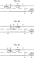
- Fig. 3A illustrates the example in which the position of the oncoming vehicle 51 is located behind the switch line 60 as viewed from the host vehicle 50
- Fig. 3B illustrates the example in which the position of the oncoming vehicle 51 is located in front of the switch line 60 as viewed from the host vehicle 50
- the determination of whether the position of the oncoming vehicle 51 is located behind or in front of the switch line 60 as viewed from the host vehicle 50 is not limited to the cases illustrated in Fig. 3A and Fig. 3B .
- the position of the oncoming vehicle 51 may be determined to be located either behind the switch line 60 or in front of the switch line 60 as viewed from the host vehicle 50.
- the position of the oncoming vehicle 51 may be determined to be located behind the switch line 60.
- the position of the oncoming vehicle 51 may be determined to be located in front of the switch line 60.
- the cases illustrated above are each presumed as a situation in which the host vehicle 50 and the oncoming vehicle 51 cannot pass the parked vehicle 52 simultaneously, or a situation in which the host vehicle 50 and the oncoming vehicle 51 could pass the parked vehicle 52 simultaneously but should avoid the simultaneous passing because there is still a probability of collision therebetween.
- the host vehicle 50 and the oncoming vehicle 51 could safely pass the parked vehicle 52 simultaneously depending on the road width, the vehicle width of the parked vehicle 52, the vehicle width of the host vehicle 50, and the vehicle width of the oncoming vehicle 51.
- the conditions for enabling the host vehicle 50 and the oncoming vehicle 51 to safely pass the parked vehicle 52 simultaneously are the spaces sufficient to avoid a collision between the oncoming vehicle 51 and the parked vehicle 52 and a collision between the host vehicle 50 and the oncoming vehicle 51.
- the sensor 11 detects a width W1 in which the oncoming vehicle 51 can keep traveling while avoiding the parked vehicle 52, as illustrated in Fig. 4 .
- the width W1 can be obtained such that the vehicle width of the oncoming vehicle 51 is added to the space sufficient to avoid a collision between the oncoming vehicle 51 and the parked vehicle 52.
- the sensor 11 detects a remaining lane width W2 obtained such that the vehicle width of the parked vehicle 52 (the vehicle width overlapping with the road) and the width W1 are subtracted from the entire road width.
- the passing position calculation unit 24 determines whether the remaining lane width W2 is sufficient to avoid a collision between the host vehicle 50 and the oncoming vehicle 51 when passing each other. When the remaining lane width W2 is sufficient to avoid a collision between the host vehicle 50 and the oncoming vehicle 51 when passing each other, the host vehicle 50 and the oncoming vehicle 51 each can decelerate so as to pass each other in the narrow road.
- the switch line setting unit 21 sets the virtual switch line 60 extending in the lane width direction in the oncoming lane at the position distant from the parked vehicle 52 by the predetermined distance in the traveling direction of the host vehicle 50.
- the method of setting the switch line 60 is not limited to the case described above.
- the switch line setting unit 21 may set the switch line 60 by use of a velocity profile.
- the method of setting the switch line 60 by use of the velocity profile is described below with reference to Fig. 5 .
- the term "velocity profile" as used herein refers to time-series data of velocities.
- the switch line setting unit 21 sets a second stop line 63 before setting the switch line 60.
- the second stop line 63 is located at a position at which the oncoming vehicle 51 is presumed to stop in front of the parked vehicle 52.
- the second stop line 63 is set at a position allowing the oncoming vehicle 51 in the stopped state to start avoiding and passing by the parked vehicle 52.
- the oncoming vehicle 51 should stop at a position distant from the parked vehicle 52 to some extent so that the oncoming vehicle 51 in the stopped state can avoid and pass by the parked vehicle 52. Determining the position distant from the parked vehicle 52 at which the oncoming vehicle 51 should stop depends on the vehicle width and the parked position of the parked vehicle 52, for example.
- the second stop line 63 is preferably set at the position depending on the vehicle width and the parked position of the parked vehicle 52, but may be set at a position having a predetermined distance sufficient to avoid the parked vehicle 52.
- the switch line setting unit 21 After setting the second stop line 63, the switch line setting unit 21 generates a velocity profile V3 that leads the oncoming vehicle 51 to stop at the second stop line 63 after starting decelerating at a constant deceleration rate from the current position of the oncoming vehicle 51.
- the velocity profile V3 in the first embodiment is set on the presumption that the intention of the driver of the oncoming vehicle 51 is to wait for the host vehicle 50 to pass the parked vehicle 52.
- the switch line setting unit 21 sets the switch line 60 at a position P3 at which a velocity regarding the velocity profile V3 is a predetermined velocity V4.
- a position P2 illustrated in Fig. 5 is a position at which the second stop line 63 is set.
- the velocity determination unit 25 determines the velocity of the host vehicle 50 based on the velocity profile V3. In particular, when the position of the oncoming vehicle 51 is located behind the switch line 60 as viewed from the host vehicle 50, the velocity determination unit 25 subtracts the velocity regarding the velocity profile V3 from the velocity of the oncoming vehicle 51 to calculate a velocity difference. The velocity determination unit 25 then determines the velocity of the host vehicle 50 in accordance with the calculated velocity difference.
- the velocity of the oncoming vehicle 51 located behind the switch line 60 as viewed from the host vehicle 50 is classified into the following three cases: the velocity of the oncoming vehicle 51 is greater than the velocity regarding the velocity profile V3, the velocity of the oncoming vehicle 51 is less than the velocity regarding the velocity profile V3, and the velocity of the oncoming vehicle 51 is substantially the same as the velocity regarding the velocity profile V3.
- a velocity V5 illustrated in Fig. 5 refers to the case in which the velocity of the oncoming vehicle 51 located behind the switch line 60 as viewed from the host vehicle 50 is greater than the velocity profile V3.
- a velocity V6 illustrated in Fig. 5 refers to the case in which the velocity of the oncoming vehicle 51 located behind the switch line 60 as viewed from the host vehicle 50 is less than the velocity profile V3.
- the reason that the velocity determination unit 25 calculates the velocity difference is to classify to determine whether the velocity of the oncoming vehicle 51 is greater than, is less than, or is substantially the same as the estimated velocity.
- the intention of the driver of the oncoming vehicle 51 is estimated in accordance with the result of the classification.
- the velocity of the oncoming vehicle 51 is determined to be greater than the estimated velocity.
- the intention of the driver of the oncoming vehicle 51 is estimated to pass by the parked vehicle 52 without waiting for the host vehicle 50.
- the velocity determination unit 25 in this case thus determines the deceleration rate of the host vehicle 50 so as to smoothly stop at the stop line 61 in order to avoid a collision between the oncoming vehicle 51 and the host vehicle 50.
- the velocity of the oncoming vehicle 51 is determined to be less than the estimated velocity.
- the intention of the driver of the oncoming vehicle 51 is estimated to wait for the host vehicle 50 to pass the parked vehicle 52.
- the velocity determination unit 25 in this case thus determines to cause the host vehicle 50 to keep the current velocity or accelerate so as to lead the host vehicle 50 to pass the parked vehicle 52 before the oncoming vehicle 51.
- the velocity of the oncoming vehicle 51 is determined to be substantially the same as the estimated velocity.
- the intention of the driver of the oncoming vehicle 51 is estimated to wait for the host vehicle 50 to pass the parked vehicle 52.
- the velocity determination unit 25 in this case thus determines to cause the host vehicle 50 to keep the current velocity or accelerate so as to lead the host vehicle 50 to pass the parked vehicle 52 before the oncoming vehicle 51.
- the velocity difference described above refers to a difference calculated at a certain time. Since a velocity of a vehicle can vary, the comparison of the velocity difference at a certain time sometimes does not lead to an accurate result.
- the velocity determination unit 25 can compare the velocity difference for a predetermined time. For example, as illustrated in Fig. 5 , the velocity determination unit 25 estimates that the intention of the driver of the oncoming vehicle 51 is to pass by the parked vehicle 52 without waiting for the host vehicle 50 when the velocity of the oncoming vehicle 51 is constantly greater than the velocity regarding the velocity profile V3 (for example, the velocity V5) for a predetermined time.
- the velocity determination unit 25 determines the deceleration rate of the host vehicle 50 so as to smoothly stop at the stop line 61 in order to avoid a collision between the oncoming vehicle 51 and the host vehicle 50.
- the velocity determination unit 25 estimates that the intention of the driver of the oncoming vehicle 51 is to wait for the host vehicle 50 to pass the parked vehicle 52.
- the velocity determination unit 25 in this case determines to cause the host vehicle 50 to keep the current velocity or accelerate so as to lead the host vehicle 50 to pass the parked vehicle 52 before the oncoming vehicle 51.
- the velocity calculation unit 25 may calculate an average of the velocities of the oncoming vehicle 51 for a predetermined time to use the calculated average for the comparison.
- the velocity determination unit 25 subtracts the velocity regarding the velocity profile V3 from the average of the velocities of the oncoming vehicle 51 to calculate a second velocity difference.
- the velocity determination unit 25 determines the velocity of the host vehicle 50 in accordance with the calculated second velocity difference.
- the calculated second velocity difference is a third predetermined value or greater, the velocity of the oncoming vehicle 51 is presumed to be greater than the estimated velocity. Namely, the intention of the driver of the oncoming vehicle 51 is estimated to pass by the parked vehicle 52 without waiting for the host vehicle 50.
- the velocity determination unit 25 determines the deceleration rate of the host vehicle 50 so as to smoothly stop at the stop line 61 in order to avoid a collision between the oncoming vehicle 51 and the host vehicle 50.
- the velocity of the oncoming vehicle 51 is presumed to be less than the estimated velocity. Namely, the intention of the driver of the oncoming vehicle 51 is estimated to wait for the host vehicle 50 to pass the parked vehicle 52.
- the velocity determination unit 25 in this case thus determines to cause the host vehicle 50 to keep the current velocity or accelerate so as to lead the host vehicle 50 to pass the parked vehicle 52 before the oncoming vehicle 51.
- the velocity of the oncoming vehicle 51 is presumed to be substantially the same as the estimated velocity. Namely, the intention of the driver of the oncoming vehicle 51 is estimated to wait for the host vehicle 50 to pass the parked vehicle 52.
- the velocity determination unit 25 determines to cause the host vehicle 50 to keep the current velocity or accelerate so as to lead the host vehicle 50 to pass the parked vehicle 52 before the oncoming vehicle 51.
- a median or a mode may be used for the comparison.
- the velocity determination unit 25 estimates that the intention of the driver of the oncoming vehicle 51 is to pass by the parked vehicle 52 without waiting for the host vehicle 50 when the position of the oncoming vehicle 51 is in front of the switch line 60 as viewed from the host vehicle 50, and when the velocity of the oncoming vehicle 51 is increased.
- the phrase "the velocity of the oncoming vehicle 51 is increased" in this case refers to a state in which the velocity of the oncoming vehicle 51 is increased more than the predetermined velocity V4, such as a velocity V7 as illustrated in Fig. 6 , for example.
- the velocity determination unit 25 estimates that the intention of the driver of the oncoming vehicle 51 is to wait for the host vehicle 50 to pass the parked vehicle 52 when the position of the oncoming vehicle 51 is in front of the switch line 60 as viewed from the host vehicle 50, and when the velocity of the oncoming vehicle 51 is not increased.
- the phrase "the velocity of the oncoming vehicle 51 is not increased” in this case refers to a case in which the velocity of the oncoming vehicle 51 is the same as the predetermined velocity V4, such as a velocity V8 as illustrated in Fig. 6 , for example.
- the phrase “the velocity of the oncoming vehicle 51 is not increased” also refers to a state in which the velocity of the oncoming vehicle 51 is decreased to fall below the velocity V4, such as a velocity V9 as illustrated in Fig. 6 , for example.
- the velocity profile V3 described above is generated by the switch line setting unit 21, but is not limited to the case of being generated.
- velocity profile models acquired from data of multiple drivers may be preliminarily prepared to obtain a corresponding velocity profile model.
- the term "data of multiple drivers” includes the data of the velocity of the oncoming vehicle 51 in the situation as illustrated in Fig. 2 , for example.
- An appropriate velocity profile model is chosen from the prepared plural velocity profile models depending on the position and the velocity of the oncoming vehicle 51.
- the switch line setting unit 21 may set the switch line 60 so as to overlap with the stop line 70 at the pedestrian crossing. Namely, the switch line setting unit 21 may set the switch line 60 at a position corresponding to the stop line 70 at the pedestrian crossing.
- the switch line setting unit 21 may set the switch line 60 immediately in front of a position at which the oncoming vehicle 51 enters the intersecting point.
- the switch line setting unit 21 may set the switch line 60 immediately in front of a position at which the oncoming vehicle 51 enters the junction of the three roads.
- the switch line setting unit 21 may set the switch line 60 immediately in front of a position at which the oncoming vehicle 51 enters the junction of the three roads.
- the switch line setting unit 21 may set the switch line 60 immediately in front of a position at which the oncoming vehicle 51 enters the intersection.
- junction of three roads or “intersection” refers to a position at which two or more roads intersect with reach other.
- the junction of three roads includes a T-junction and a Y-junction.
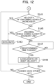
- step S101 the controller 20 acquires the map information from the map database 12.
- step S103 the position detection sensors such as the GPS receiver 10 and the odometry detect the positional information of the host vehicle 50.
- step S105 When the parked vehicle 52 and the oncoming vehicle 51 are detected by the sensor 11 (YES in step S105), the process proceeds to step S107. When either the parked vehicle 52 or the oncoming vehicle 51 is not detected (NO in step S1 05), the series of processing ends.
- step S107 the switch line setting unit 21 sets the virtual switch line 60 extending in the lane width direction in the oncoming lane at a position distant from the parked vehicle 52 by a predetermined distance in the traveling direction of the host vehicle 50 (refer to Fig. 2 ).
- the switch line setting unit 21 may set the switch line 60 by use of the velocity profile V3 (refer to Fig. 5 ).
- the process proceeds to step S109, and the stop line setting unit 22 sets the virtual stop line 61 extending in the lane width direction in the traveling lane at a position distant from the parked vehicle 52 by a predetermined distance in the traveling direction of the oncoming vehicle 51 (refer to Fig. 2 ).
- step S111 the no-passing region setting unit 23 sets the no-passing region R by use of the switch line 60 and the stop line 61 set in step S107 and S109 (refer to Fig. 2 ).
- step S113 the passing position calculation unit 24 determines whether the position P1 at which the host vehicle 50 and the oncoming vehicle 51 pass each other is present within the no-passing region R set in step S111.
- step S115 When the position P1 at which the host vehicle 50 and the oncoming vehicle 51 pass each other is present within the no-passing region R (YES in step S115), the process proceeds to step S117. When the position P1 at which the host vehicle 50 and the oncoming vehicle 51 pass each other is not present within the no-passing region R (NO in step S115), the process proceeds to step S123.
- step S117 the sensor 11 detects the width W1 in which the oncoming vehicle 51 can keep traveling while avoiding the parked vehicle 52 (refer to Fig. 4 ).
- the sensor 11 detects the remaining lane width W2 obtained such that the vehicle width of the parked vehicle 52 and the width W1 are subtracted from the entire road width (refer to Fig. 4 ).
- the process proceeds to step S119, and the passing position calculation unit 24 determines whether the remaining lane width W2 detected in step S117 is sufficient to avoid a collision between the host vehicle 50 and the oncoming vehicle 51 when passing each other (in step S1 19).
- step S119 When the result of the determination is YES in step S119, the process proceeds to step S121, and the host vehicle 50 is caused to keep traveling to pass the oncoming vehicle 51 in the narrow road. When the host vehicle 50 and the oncoming vehicle 51 have passed each other (YES in step S123), the series of processing ends.
- step S125 When the result of the determination is NO in step S119, the process proceeds to step S125.
- step S125 the velocity determination unit 25 subtracts the velocity regarding the velocity profile V3 from the velocity of the oncoming vehicle 51 to calculate the velocity difference.
- the velocity determination unit 25 classifies to determine whether the velocity of the oncoming vehicle 51 is greater than, is less than, or is substantially the same as the estimated velocity in accordance with the velocity difference.
- step S131 the velocity determination unit 25 estimates that the intention of the driver of the oncoming vehicle 51 is to pass by the parked vehicle 52 without waiting for the host vehicle 50.
- the velocity determination unit 25 determines the deceleration rate of the host vehicle 50 so as to smoothly stop at the stop line 61 in order to avoid a collision between the oncoming vehicle 51 and the host vehicle 50.
- the vehicle control unit 26 decelerates the host vehicle 50 by use of the brake actuator at the deceleration rate determined by the velocity determination unit 25. The process then proceeds to step S139.
- step S133 When the velocity of the oncoming vehicle 51 is not greater than the velocity regarding the velocity profile V3 (NO in step S129), the process proceeds to step S133.
- the process proceeds to step S135, and the velocity determination unit 25 estimates that the intention of the driver of the oncoming vehicle 51 is to wait for the host vehicle 50 to pass the parked vehicle 52.
- the velocity determination unit 25 determines to cause the host vehicle 50 to accelerate so as to lead the host vehicle 50 to pass the parked vehicle 52 before the oncoming vehicle 51.
- the vehicle control unit 26 accelerates the host vehicle 50 by use of the acceleration actuator.
- step S139 The processing in step S139 is the same as that in step S123, and overlapping explanations are not repeated below.
- step S133 When the velocity of the oncoming vehicle 51 is the same or substantially the same as the velocity regarding the velocity profile V3 (NO in step S133), the process proceeds to step S137, and the velocity determination unit 25 estimates that the intention of the driver of the oncoming vehicle 51 is to wait for the host vehicle 50 to pass the parked vehicle 52. The velocity determination unit 25 then determines to cause the host vehicle 50 to keep the velocity so as to lead the host vehicle 50 to pass the parked vehicle 52 before the oncoming vehicle 51. The process then proceeds to step S141. When the position of the oncoming vehicle 51 is located in front of the switch line 60 as viewed from the host vehicle 50 (NO in step S125) (refer to Fig. 3B ), the process also proceeds to step S141. The process may proceed to step S139 after the processing in step S137.
- step S141 When the position of the oncoming vehicle 51 is located in front of the switch line 60 as viewed from the host vehicle 50, and when the velocity of the oncoming vehicle 51 is increased (YES in step S141), the process proceeds to step S143, and the velocity determination unit 25 estimates that the intention of the driver of the oncoming vehicle 51 is to pass by the parked vehicle 52 without waiting for the host vehicle 50.
- the velocity determination unit 25 determines the deceleration rate of the host vehicle 50 so as to smoothly stop at the stop line 61 in order to avoid a collision between the oncoming vehicle 51 and the host vehicle 50.
- the vehicle control unit 26 decelerates the host vehicle 50 by use of the brake actuator at the deceleration rate determined by the velocity determination unit 25. The process then proceeds to step S151.
- step S145 When the position of the oncoming vehicle 51 is located in front of the switch line 60 as viewed from the host vehicle 50, and when the velocity of the oncoming vehicle 51 is not increased (NO in step S141), the process proceeds to step S145.
- the position of the oncoming vehicle 51 is located in front of the switch line 60 as viewed from the host vehicle 50, and when the oncoming vehicle 51 is coming close to the boundary line 62 indicating the boundary between the traveling lane and the oncoming lane (YES in step S145), the process proceeds to step S143.
- step S145 When the position of the oncoming vehicle 51 is located in front of the switch line 60 as viewed from the host vehicle 50, and when the oncoming vehicle 51 does not come close to the boundary line 62 (NO in step S145), the velocity determination unit 25 estimates that the intention of the driver of the oncoming vehicle 51 is to wait for the host vehicle 50 to pass the parked vehicle 52. After a lapse of predetermined time period (YES in step S147), the velocity determination unit 25 then determines to cause the host vehicle 50 to keep the current velocity or accelerate so as to lead the host vehicle 50 to pass the parked vehicle 52 before the oncoming vehicle 51 (in step S149). The reason for executing the processing in step S147 is to confirm that the estimated intention of the driver of the oncoming vehicle 51 is not changed. After the processing in step S149, the process proceeds to step S151.
- the processing in step S151 is the same as that in step S123, and overlapping explanations are not repeated below.
- the vehicle control device 1 can achieve the following operational effects.
- the switch line setting unit 21 sets the virtual switch line 60 extending in the lane width direction in the oncoming lane at a position distant from the parked vehicle 52 by a predetermined distance in the traveling direction of the host vehicle 50.
- the stop line setting unit 22 sets the virtual stop line 61 in the traveling lane at a position distant from the parked vehicle 52 by a predetermined distance in the traveling direction of the oncoming vehicle 51.
- the no-passing region setting unit 23 sets the no-passing region R including the switch line 60 and the stop line 61 on the road.
- the passing position calculation unit 24 calculates the position P1 at which the host vehicle 50 and the oncoming vehicle 51 pass each other in accordance with the velocity of the host vehicle 50 and the position and the velocity of the oncoming vehicle 51.
- the velocity determination unit 25 estimates that the intention of the driver of the oncoming vehicle 51 is to pass by the parked vehicle 52 without waiting for the host vehicle 50.
- the velocity determination unit 25 determines the deceleration rate of the host vehicle 50 so as to smoothly stop at the stop line 61 in order to avoid a collision between the oncoming vehicle 51 and the host vehicle 50.
- the velocity determination unit 25 estimates that the intention of the driver of the oncoming vehicle 51 is to wait for the host vehicle 50 to pass the parked vehicle 52.
- the velocity determination unit 25 determines to cause the host vehicle 50 to keep the current velocity or accelerate so as to lead the host vehicle 50 to pass the parked vehicle 52 before the oncoming vehicle 51.
- the vehicle control unit 26 controls the respective actuators 30 so as to lead the host vehicle 50 to travel at the determined velocity.
- the vehicle control device 1 according to the first embodiment as described above estimates the intention of the driver of the oncoming vehicle 51, and determines the velocity of the host vehicle 50 in accordance with the estimated intention, so as to avoid sudden braking or unnecessary acceleration or deceleration.
- the vehicle control unit 26 causes the host vehicle 50 to decelerate so as to stop at the stop line 61. This control can avoid preventing the oncoming vehicle 51 from passing the parked vehicle 52, so as to ensure the smooth traveling.
- the switch line setting unit 21 may set the switch line 60 based on a position at which the oncoming vehicle 51 can stop.
- the position at which the oncoming vehicle 51 can stop is the stop line 70 at the pedestrian crossing (the actual stop line), as illustrated in Fig. 7 , for example.
- the position at which the oncoming vehicle 51 can stop is set immediately in front of the position at which the oncoming vehicle 51 enters the point at which two or more roads intersect with each other, as illustrated in Fig. 8 or Fig. 9 , for example.
- Setting the switch line 60 as described above can execute the traveling control for the host vehicle 50 depending on the intention of the driver of the oncoming vehicle 51 that is to decelerate toward the switch line 60, to pass through the switch line 60, or to stop at the switch line 60.
- the switch line setting unit 21 may set the switch line 60 in accordance with the velocity profile.
- the switch line setting unit 21 sets the virtual second stop line 63 in the oncoming lane at the position distant from the parked vehicle 52 by the predetermined distance (the second predetermined distance) in the traveling direction of the host vehicle 50.
- the switch line setting unit 21 acquires or generates the velocity profile V3 that leads the oncoming vehicle 51 to stop at the second stop line 63 by use of the position and the velocity of the oncoming vehicle 51.
- the switch line setting unit 21 then sets the switch line 60 at the position at which the velocity regarding the velocity profile V3 corresponds to the predetermined velocity V4 (the second predetermined velocity).
- the velocity determination unit 25 estimates the intention of the driver of the oncoming vehicle 51 by use of the switch line 60, and determines the velocity of the host vehicle 50 while taking account of the estimated intention. This configuration enables the control of the host vehicle 50 in accordance with the intention of the driver of the oncoming vehicle 51.
- the velocity determination unit 25 subtracts the velocity regarding the velocity profile V3 from the velocity of the oncoming vehicle 51 to calculate the velocity difference, so as to classify to determine whether the velocity of the oncoming vehicle 51 is greater than, is less than, or is substantially the same as the estimated velocity, in accordance with the calculated velocity difference.
- This configuration enables the control of the host vehicle 50 in accordance with the intention of the driver of the oncoming vehicle 51, so as to avoid sudden braking or unnecessary acceleration or deceleration accordingly.
- the velocity determination unit 25 may estimate the intention of the driver of the oncoming vehicle 51 in accordance with the positional relationship between the oncoming vehicle 51 and the boundary line 62 indicating the boundary between the traveling lane and the oncoming lane, or in accordance with the acceleration rate of the oncoming vehicle 51. This configuration enables the control of the host vehicle 50 in accordance with the intention of the driver of the oncoming vehicle 51, so as to avoid sudden braking or unnecessary acceleration or deceleration accordingly.
- the velocity determination unit 25 may determine the velocity of the host vehicle 50 only by use of the acceleration rate of the oncoming vehicle 51.
- the velocity determination unit 25 may estimate that the intention of the driver of the oncoming vehicle 51 is to pass by the parked vehicle 52 without waiting for the host vehicle 50.
- the velocity determination unit 25 in this case may determine the deceleration rate of the host vehicle 50 so as to smoothly stop at the stop line 61 in order to avoid a collision between the oncoming vehicle 51 and the host vehicle 50.
- the velocity determination unit 25 may estimate that the intention of the driver of the oncoming vehicle 51 is to wait for the host vehicle 50 to pass the parked vehicle 52.
- the velocity determination unit 25 in this case may determine to cause the host vehicle 50 to keep the current velocity or accelerate so as to lead the host vehicle 50 to pass the parked vehicle 52 before the oncoming vehicle 51.
- the vehicle control device 1 estimates the intention of the driver of the oncoming vehicle 51 only by use of the acceleration rate of the oncoming vehicle 51, so as to determine the velocity of the host vehicle 50 in accordance with the estimated intention. This can avoid sudden braking or unnecessary acceleration or deceleration.
- the present invention is described below with reference to Fig. 13 to Fig. 16 .
- the same elements as described in the first embodiment are denoted by the same reference numerals, and overlapping explanations are not repeated below.
- the following explanations are made mainly with regard to the different points.
- the second embodiment is illustrated with the case in which the passing position P1 is presumed to be present within the no-passing region R.
- a vehicle control device 2 includes a velocity threshold setting unit 27 and a velocity comparison unit 28.
- the vehicle control device 2 differs from the vehicle control device 1 according to the first embodiment in not including the switch line setting unit 21 or the stop line setting unit 22.
- the velocity threshold setting unit 27 sets a velocity threshold used in the velocity comparison unit 28.
- the velocity threshold setting unit 27 generates a velocity profile that leads the oncoming vehicle 51 to stop in front of the parked vehicle 52 after starting decelerating at a constant deceleration rate from a certain position (which can be the current position) of the oncoming vehicle 51.
- the velocity regarding the velocity profile generated by the velocity threshold setting unit 27 is greater as the distance between the parked vehicle 52 and the oncoming vehicle 51 is longer.
- the velocity threshold setting unit 27 sets a velocity threshold based on the generated velocity profile.
- the velocity threshold setting unit 27 sets the velocity regarding the velocity profile as a velocity threshold corresponding to a position of the oncoming vehicle 51 distant from the parked vehicle 52 by a predetermined distance (a distance L3).
- the set velocity threshold in the example illustrated in Fig. 15 is V10.
- Fig. 16 illustrates another example in which the velocity threshold setting unit 27 sets the velocity regarding the velocity profile as a velocity threshold corresponding to a position of the oncoming vehicle 51 distant from the parked vehicle 52 by a predetermined distance (a distance L4).
- the set velocity threshold in the example illustrated in Fig. 16 is V11.
- the examples described above satisfy the relations of L3 > L4, and V10 > V11. The velocity threshold is thus greater as the distance between the parked vehicle 52 and the oncoming vehicle 51 is longer.
- the velocity comparison unit 28 compares the velocity threshold set by the velocity threshold setting unit 27 with the velocity of the oncoming vehicle 51.
- the velocity comparison unit 28 compares the velocity threshold V10 corresponding to the position of the oncoming vehicle 51 distant from the parked vehicle 52 by the distance L3 with the velocity of the oncoming vehicle 51 corresponding to the position of the oncoming vehicle 51 distant from the parked vehicle 52 by the distance L3.
- the velocity comparison unit 28 outputs the result of the comparison to the velocity determination unit 25.
- the velocity determination unit 25 estimates that the intention of the driver of the oncoming vehicle 51 is to pass by the parked vehicle 52 without waiting for the host vehicle 50.
- the velocity determination unit 25 in this case determines the deceleration rate of the host vehicle 50 so as to smoothly stop at the stop line 61 in order to avoid a collision between the oncoming vehicle 51 and the host vehicle 50.
- the velocity determination unit 25 estimates that the intention of the driver of the oncoming vehicle 51 is to wait for the host vehicle 50 to pass the parked vehicle 52.
- the velocity determination unit 25 determines to cause the host vehicle 50 to keep the current velocity or accelerate so as to lead the host vehicle 50 to pass the parked vehicle 52 before the oncoming vehicle 51.
- the vehicle control device 2 estimates the intention of the driver of the oncoming vehicle 51, and determines the velocity of the host vehicle 50 in accordance with the estimated intention, so as to avoid sudden braking or unnecessary acceleration or deceleration.
- the no-passing region setting unit 23 sets the no-passing region R without using the switch line 60 or the stop line 61.
- the no-passing region setting unit 23 can set the no-passing region R on the road defined in a predetermined region in the road extending direction including the parked vehicle 52 (refer to Fig. 14 ).
- a modified example 1 according to the second embodiment is described below.
- the vehicle control device 2 is illustrated above with the case of not including the switch line setting unit 21, but is not limited to this case.
- the vehicle control device 2 may include the switch line setting unit 21.
- the velocity comparison unit 28 can compare the velocity threshold with the velocity of the oncoming vehicle 51 by use of the switch line 60.
- the velocity comparison unit 28 compares the velocity threshold with the velocity of the oncoming vehicle 51 when the position of the oncoming vehicle 51 is located behind the switch line 60 in the traveling direction of the host vehicle 50 as viewed from the host vehicle 50.
- the method of determining the velocity in accordance with the result of the comparison is the same as described above, and overlapping explanations are not repeated below.
- the vehicle control device 2 according to the modified example 1 as described above estimates the intention of the driver of the oncoming vehicle 51, and determines the velocity of the host vehicle 50 in accordance with the estimated intention, so as to avoid sudden braking or unnecessary acceleration or deceleration.
- a modified example 2 according to the second embodiment is described below.
- the vehicle control device 2 according to the modified example 2 also includes the switch line setting unit 21.
- the vehicle control device 2 according to the modified example 2 has the functions similar to those in the vehicle control device 2 according to the modified example 1.
- the vehicle control device 2 according to the modified example 2 estimates the intention of the driver of the oncoming vehicle 51 by use of the acceleration rate of the oncoming vehicle 51 in addition to the velocity of the oncoming vehicle 51.
- the velocity determination unit 25 may estimate that the intention of the driver of the oncoming vehicle 51 is to pass by the parked vehicle 52 without waiting for the host vehicle 50.
- the velocity determination unit 25 in this case may determine the deceleration rate of the host vehicle 50 so as to smoothly stop at the stop line 61 in order to avoid a collision between the oncoming vehicle 51 and the host vehicle 50.
- the velocity determination unit 25 may estimate that the intention of the driver of the oncoming vehicle 51 is to wait for the host vehicle 50 to pass the parked vehicle 52.
- the velocity determination unit 25 in this case may determine to cause the host vehicle 50 to keep the current velocity or accelerate so as to lead the host vehicle 50 to pass the parked vehicle 52 before the oncoming vehicle 51.
- the vehicle control device 2 according to the modified example 2 as described above estimates the intention of the driver of the oncoming vehicle 51, so as to determine the velocity of the host vehicle 50 in accordance with the estimated intention. This can avoid sudden braking or unnecessary acceleration or deceleration accordingly.
- a modified example 3 according to the second embodiment is described below.
- the vehicle control device 2 according to the modified example 3 also includes the switch line setting unit 21.
- the vehicle control device 2 according to the modified example 3 has the functions similar to those in the vehicle control device 2 according to the modified example 1.
- the vehicle control device 2 according to the modified example 3 estimates the intention of the driver of the oncoming vehicle 51 by use of the velocity and the acceleration rate of the oncoming vehicle 51 on the front side of the switch line 60.
- the velocity determination unit 25 may estimate that the intention of the driver of the oncoming vehicle 51 is to pass by the parked vehicle 52 without waiting for the host vehicle 50.
- the velocity determination unit 25 in this case may determine the deceleration rate of the host vehicle 50 so as to smoothly stop at the stop line 61 in order to avoid a collision between the oncoming vehicle 51 and the host vehicle 50.
- the velocity determination unit 25 may estimate that the intention of the driver of the oncoming vehicle 51 is to wait for the host vehicle 50 to pass the parked vehicle 52.
- the velocity determination unit 25 in this case may determine to cause the host vehicle 50 to keep the current velocity or accelerate so as to lead the host vehicle 50 to pass the parked vehicle 52 before the oncoming vehicle 51.
- the vehicle control device 2 according to the modified example 3 as described above estimates the intention of the driver of the oncoming vehicle 51, so as to determine the velocity of the host vehicle 50 in accordance with the estimated intention. This can avoid sudden braking or unnecessary acceleration or deceleration accordingly.
- the respective functions described above in the respective embodiments can be implemented in single or plural processing circuits.
- the respective processing circuits include a programmed processing device, such as a processing device including an electric circuit.
- the respective processing circuits include an application-specific integrated circuit (ASIC) configured to execute the functions described above, and a device such as a circuit component.
- ASIC application-specific integrated circuit
- the vehicle control devices described above can improve the functions of the computer.
Landscapes
- Engineering & Computer Science (AREA)
- Automation & Control Theory (AREA)
- Transportation (AREA)
- Mechanical Engineering (AREA)
- Physics & Mathematics (AREA)
- Mathematical Physics (AREA)
- Control Of Driving Devices And Active Controlling Of Vehicle (AREA)
- Traffic Control Systems (AREA)
Claims (17)
- Procédé de contrôle de véhicule comprenant :la détection d'une position d'un objet stationnaire (52) sur une route sur laquelle circule un véhicule hôte (50) ;la détection d'une vitesse du véhicule hôte (50) ;la détection d'une position et d'une vitesse d'un véhicule en approche (51) circulant dans une direction opposée à une direction de circulation du véhicule hôte (50) dans une voie d'approche adjacente à une voie de circulation dans laquelle circule le véhicule hôte (50) ;l'établissement d'une région (R) sur la route définie dans une direction d'extension de la route incluant l'objet stationnaire (52) ;le calcul d'une position de dépassement à laquelle le véhicule hôte (50) et le véhicule en approche (51) se dépassent conformément à la vitesse du véhicule hôte (50) et à la position et à la vitesse du véhicule en approche (51) ;caractérisé parl'établissement d'un seuil de vitesse qui est d'autant plus élevé que la distance entre l'objet stationnaire (52) et le véhicule en approche (51) est grande ;la commande au véhicule hôte (50) de décélérer quand la vitesse du véhicule en approche (51) correspondant à la position du véhicule en approche (51) distante de l'objet stationnaire (52) d'une distance prédéterminée est supérieure ou égale au seuil de vitesse correspondant à la position du véhicule en approche (51) distante de l'objet stationnaire (52) de la distance prédéterminée dans le cas où la position de dépassement est présente dans la région (R) ; etla commande au véhicule hôte (50) de maintenir la vitesse ou d'accélérer quand la vitesse du véhicule en approche (51) correspondant à la position du véhicule en approche (51) distante de l'objet stationnaire (52) de la distance prédéterminée est inférieure au seuil de vitesse correspondant à la position du véhicule en approche (51) distante de l'objet stationnaire (52) de la distance prédéterminée dans le cas où la position de dépassement est présente dans la région (R).
- Procédé de contrôle de véhicule selon la revendication 1, comprenant en outrel'établissement d'une ligne de commutation virtuelle (60) qui s'étend en direction de la largeur de voie dans la voie d'approche à une position distante de l'objet stationnaire (52) d'une distance prédéterminée dans la direction de circulation du véhicule hôte (50),dans lequel, dans le cas où la position de dépassement est présente dans la région (R), le véhicule hôte (50) est commandé pour décélérer quand la position du véhicule en approche (51) est située derrière la ligne de commutation (60) dans la direction de circulation du véhicule hôte (50) vu depuis le véhicule hôte (50), et la vitesse du véhicule en approche (51) correspondant à la position du véhicule en approche (51) distante de l'objet stationnaire (52) de la distance prédéterminée est supérieure ou égale au seuil de vitesse correspondant à la position du véhicule en approche (51) distante de l'objet stationnaire (52) de la distance prédéterminée, etdans le cas où la position de dépassement est présente dans la région (R), le véhicule hôte (50) est commandé pour maintenir la vitesse ou pour accélérer quand la position du véhicule en approche (51) est située derrière la ligne de commutation (60) dans la direction de circulation du véhicule hôte (50) vu depuis le véhicule hôte (50), et la vitesse du véhicule en approche (51) correspondant à la position du véhicule en approche (51) distante de l'objet stationnaire (52) de la distance prédéterminée est inférieure au seuil de vitesse correspondant à la position du véhicule en approche (51) distante de l'objet stationnaire (52) de la distance prédéterminée.
- Procédé de contrôle de véhicule selon la revendication 2, dans lequel :dans le cas où la position de dépassement est présente dans la région (R), le véhicule hôte (50) est commandé pour décélérer quand la position du véhicule en approche (51) est située devant la ligne de commutation (60) dans la direction de circulation du véhicule hôte (50) vu depuis le véhicule hôte (50), et la vitesse du véhicule en approche (51) est augmentée ; etdans le cas où la position de dépassement est présente dans la région (R), le véhicule hôte (50) est commandé pour maintenir la vitesse ou pour accélérer quand la position du véhicule en approche est située devant la ligne de commutation (60) dans la direction de circulation du véhicule hôte (50) vu depuis le véhicule hôte (50), et la vitesse du véhicule en approche n'est pas augmentée.
- Procédé de contrôle de véhicule selon la revendication 2, dans lequel :dans le cas où la position de dépassement est présente dans la région (R), le véhicule hôte (50) est commandé pour décélérer quand la position du véhicule en approche est située devant la ligne de commutation (60) dans la direction de circulation du véhicule hôte (50) vu depuis le véhicule hôte (50), et la vitesse du véhicule en approche (51) est supérieure ou égale au seuil de vitesse, ou la vitesse du véhicule en approche est augmentée ; etdans le cas où la position de dépassement est présente dans la région (R), le véhicule hôte (50) est commandé pour maintenir la vitesse ou pour accélérer quand la position du véhicule en approche est située devant la ligne de commutation (60) dans la direction de circulation du véhicule hôte (50) vu depuis le véhicule hôte (50), la vitesse du véhicule en approche est inférieure au seuil de vitesse, et la vitesse du véhicule en approche n'est pas augmentée.
- Procédé de contrôle de véhicule selon l'une quelconque des revendications 1 à 3, comprenant en outre :l'établissement d'une ligne de commutation virtuelle (60) qui s'étend en direction de la largeur de voie dans la voie d'approche à une position distante de l'objet stationnaire (52) d'une distance prédéterminée dans la direction de circulation du véhicule hôte (50) ;l'établissement d'une ligne d'arrêt virtuelle (61) dans la voie de circulation à une position distante de l'objet stationnaire (52) d'une distance prédéterminée dans une direction de circulation du véhicule en approche ; etl'établissement d'une région (R) sur la route définie entre la ligne de commutation (60) et la ligne d'arrêt (61) de manière à inclure la ligne de commutation (60) et la ligne d'arrêt (61),dans lequel la position de dépassement à laquelle le véhicule hôte (50) et le véhicule en approche (51) se dépassent est calculée conformément à la vitesse du véhicule hôte (50) et à la position et à la vitesse du véhicule en approche,dans le cas où la position de dépassement est présente dans la région (R), le véhicule hôte (50) est commandé pour décélérer quand la position du véhicule en approche (51) est située derrière la ligne de commutation (60) dans la direction de circulation du véhicule hôte (50) vu depuis le véhicule hôte (50), et la vitesse du véhicule en approche est supérieure ou égale à une vitesse prédéterminée, ou quand la position du véhicule en approche est située devant la ligne de commutation (60) dans la direction de circulation du véhicule hôte (50) vu depuis le véhicule hôte (50), et la vitesse du véhicule en approche est augmentée, etdans le cas où la position de dépassement est présente dans la région (R), le véhicule hôte (50) est commandé pour maintenir la vitesse ou pour accélérer quand la position du véhicule en approche est située derrière la ligne de commutation (60) dans la direction de circulation du véhicule hôte (50) vu depuis le véhicule hôte (50), et la vitesse du véhicule en approche (51) est inférieure à la vitesse prédéterminée, ou quand la position du véhicule en approche est située devant la ligne de commutation (60) dans la direction de circulation du véhicule hôte (50) vu depuis le véhicule hôte (50), et la vitesse du véhicule en approche n'est pas augmentée.
- Procédé de contrôle de véhicule selon la revendication 5, dans lequel, dans le cas où la position de dépassement est présente dans la région (R), le véhicule hôte (50) est commandé pour décélérer de manière à s'arrêter à la ligne d'arrêt (61) quand la position du véhicule en approche (51) est située derrière la ligne de commutation (60) dans la direction de circulation du véhicule hôte (50) vu depuis le véhicule hôte (50), et la vitesse du véhicule en approche est supérieure ou égale à la vitesse prédéterminée, ou quand la position du véhicule en approche est située devant la ligne de commutation (60) dans la direction de circulation du véhicule hôte (50) vu depuis le véhicule hôte (50), et la vitesse du véhicule en approche est augmentée.
- Procédé de contrôle de véhicule selon la revendication 5 ou 6, dans lequel la ligne de commutation (60) est établie conformément à une position à laquelle le véhicule en approche (51) peut s'arrêter.
- Procédé de contrôle de véhicule selon la revendication 7, comprenant en outre :l'établissement d'une deuxième ligne d'arrêt virtuelle (63) dans la voie d'approche à une position distante de l'objet stationnaire (52) d'une deuxième distance prédéterminée dans la direction de circulation du véhicule hôte (50) ; etl'acquisition ou la génération d'un profil de vitesse qui amène le véhicule en approche (51) à s'arrêter à la deuxième ligne d'arrêt (63) conformément à la position et à la vitesse du véhicule en approche,dans lequel la ligne de commutation (60) est établie à une position à laquelle une vitesse relative au profil de vitesse est une deuxième vitesse prédéterminée.
- Procédé de contrôle de véhicule selon la revendication 7, dans lequel, quand une ligne d'arrêt réelle (70) est présente derrière l'objet stationnaire (52) dans la voie d'approche, la ligne de commutation (60) est établie à une position correspondant à la ligne d'arrêt réelle (70).
- Procédé de contrôle de véhicule selon la revendication 7, dans lequel, quand un point où deux ou plusieurs routes se croisent est présent derrière l'objet stationnaire (52), la ligne de commutation (60) est établie immédiatement devant une position où le véhicule en approche entre dans le point d'intersection.
- Procédé de contrôle de véhicule selon la revendication 8, comprenant en outrela soustraction de la vitesse relative au profil de vitesse de la vitesse du véhicule en approche (51) pour calculer une différence de vitesse quand la position du véhicule en approche est située derrière la ligne de commutation (60) dans la direction de circulation du véhicule hôte (50) vu depuis le véhicule hôte (50),dans lequel le véhicule hôte (50) est commandé pour décélérer quand la différence de vitesse est supérieure ou égale à une première valeur prédéterminée,le véhicule hôte (50) est commandé pour maintenir la vitesse ou pour accélérer quand la différence de vitesse est inférieure à une deuxième valeur prédéterminée, etle véhicule hôte (50) est commandé pour maintenir la vitesse ou pour accélérer quand la différence de vitesse est inférieure à la première valeur prédéterminée et supérieure ou égale à la deuxième valeur prédéterminée.
- Procédé de contrôle de véhicule selon la revendication 8, comprenant en outrela comparaison de la vitesse du véhicule en approche (51) pendant un temps prédéterminé à la vitesse relative au profil de vitesse pendant le temps prédéterminé quand la position du véhicule en approche est située derrière la ligne de commutation (60) dans la direction de circulation du véhicule hôte (50) vu depuis le véhicule hôte (50),dans lequel le véhicule hôte (50) est commandé pour décélérer quand la vitesse du véhicule en approche pendant le temps prédéterminé est supérieure à la vitesse relative au profil de vitesse pendant le temps prédéterminé, etle véhicule hôte (50) est commandé pour maintenir la vitesse ou pour accélérer quand la vitesse du véhicule en approche pendant le temps prédéterminé est inférieure à la vitesse relative au profil de vitesse pendant le temps prédéterminé.
- Procédé de contrôle de véhicule selon la revendication 8, comprenant en outre :le calcul d'une moyenne des vitesses du véhicule en approche (51) pendant un temps prédéterminé et d'une moyenne des vitesses relatives au profil de vitesse pendant le temps prédéterminé quand la position du véhicule en approche est située derrière la ligne de commutation (60) dans la direction de circulation du véhicule hôte (50) vu depuis le véhicule hôte (50) ; etla soustraction de la moyenne des vitesses relatives au profil de vitesse pendant le temps prédéterminé de la moyenne des vitesses du véhicule en approche pendant le temps prédéterminé pour calculer une deuxième différence de vitesse,dans lequel le véhicule hôte (50) est commandé pour décélérer quand la deuxième différence de vitesse est supérieure ou égale à une troisième valeur prédéterminée,le véhicule hôte (50) est commandé pour maintenir la vitesse ou pour accélérer quand la deuxième différence de vitesse est inférieure à une quatrième valeur prédéterminée, etle véhicule hôte (50) est commandé pour maintenir la vitesse ou pour accélérer quand la deuxième différence de vitesse est inférieure à la troisième valeur prédéterminée et supérieure ou égale à la quatrième valeur prédéterminée.
- Procédé de contrôle de véhicule selon l'une quelconque des revendications 5 à 13, dans lequel :le véhicule hôte (50) est commandé pour décélérer quand la position du véhicule en approche (51) est située devant la ligne de commutation (60) dans la direction de circulation du véhicule hôte (50) vu depuis le véhicule hôte (50), et la vitesse du véhicule en approche est augmentée, ou le véhicule en approche se rapproche d'une ligne de délimitation indiquant une délimitation entre la voie de circulation et la voie d'approche ; etle véhicule hôte (50) est commandé pour maintenir la vitesse ou pour accélérer quand la position du véhicule en approche est située devant la ligne de commutation (60) dans la direction de circulation du véhicule hôte (50) vu depuis le véhicule hôte (50), et la vitesse du véhicule en approche n'est pas augmentée, ou le véhicule en approche ne s'approche pas de la ligne de délimitation.
- Procédé de contrôle de véhicule selon l'une quelconque des revendications 5 à 13, dans lequel :le véhicule hôte (50) est commandé pour décélérer quand la position du véhicule en approche (51) est située devant la ligne de commutation (60) dans la direction de circulation du véhicule hôte (50) vu depuis le véhicule hôte (50) et une accélération du véhicule en approche est supérieure ou égale à une accélération prédéterminée ;le véhicule hôte (50) est commandé pour maintenir la vitesse quand la position du véhicule en approche est située devant la ligne de commutation (60) dans la direction de circulation du véhicule hôte (50) vu depuis le véhicule hôte (50) et l'accélération du véhicule en approche est inférieure à l'accélération prédéterminée ; etle véhicule hôte (50) est commandé pour accélérer quand la position du véhicule en approche est située devant la ligne de commutation (60) dans la direction de circulation du véhicule hôte (50) vu depuis le véhicule hôte (50) et l'accélération du véhicule en approche n'atteint pas l'accélération prédéterminée dans un temps prédéterminé.
- Procédé de contrôle de véhicule selon la revendication 14, dans lequel :le véhicule hôte (50) est commandé pour décélérer quand la position du véhicule en approche (51) est située devant la ligne de commutation (60) dans la direction de circulation du véhicule hôte (50) vu depuis le véhicule hôte (50) et une distance entre la ligne de délimitation et le véhicule en approche est inférieure ou égale à une troisième distance prédéterminée ;le véhicule hôte (50) est commandé pour maintenir la vitesse quand la position du véhicule en approche est située devant la ligne de commutation (60) dans la direction de circulation du véhicule hôte (50) vu depuis le véhicule hôte (50) et la distance entre la ligne de délimitation et le véhicule en approche est supérieure à la troisième distance prédéterminée ; etle véhicule hôte (50) est commandé pour accélérer quand la position du véhicule en approche est située devant la ligne de commutation (60) dans la direction de circulation du véhicule hôte (50) vu depuis le véhicule hôte (50) et la distance entre la ligne de délimitation et le véhicule en approche ne tombe pas en dessous de la troisième distance prédéterminée dans un temps prédéterminé
- Dispositif de contrôle de véhicule comprenant :un premier capteur configuré pour détecter la position d'un objet stationnaire (52) sur une route sur laquelle circule un véhicule hôte (50) ;un deuxième capteur configuré pour détecter une vitesse du véhicule hôte (50) ;un troisième capteur configuré pour détecter la position d'un véhicule en approche (51) circulant dans une direction opposée à une direction de circulation du véhicule hôte (50) dans une voie d'approche adjacente à une voie de circulation dans laquelle circule le véhicule hôte (50) ;un quatrième capteur configuré pour détecter une vitesse du véhicule en approche ; etun contrôleur configuré pour contrôler un état de circulation du véhicule hôte (50) conformément aux données détectées par le premier capteur, le deuxième capteur, le troisième capteur et le quatrième capteur,le contrôleur étant configuré pour :établir une région (R) sur la route définie dans une direction d'extension de la route incluant l'objet stationnaire (52) ;calculer une position de dépassement à laquelle le véhicule hôte (50) et le véhicule en approche se dépassent, conformément à la vitesse du véhicule hôte (50) et à la position et à la vitesse du véhicule en approche ;caractérisé en ce quele contrôleur est en outre configuré pourétablir un seuil de vitesse qui est d'autant plus grand que la distance entre l'objet stationnaire (52) et le véhicule en approche est grande ;commander au véhicule hôte (50) de décélérer quand la vitesse du véhicule en approche correspondant à la position du véhicule en approche distante de l'objet stationnaire (52) d'une distance prédéterminée est supérieure ou égale au seuil de vitesse correspondant à la position du véhicule en approche distante de l'objet stationnaire (52) de la distance prédéterminée dans le cas où la position de dépassement est présente dans la région (R) ; etcommander au véhicule hôte (50) de maintenir la vitesse ou d'accélérer quand la vitesse du véhicule en approche correspondant à la position du véhicule en approche distante de l'objet stationnaire (52) de la distance prédéterminée est inférieure au seuil de vitesse correspondant à la position du véhicule en approche distante de l'objet stationnaire (52) de la distance prédéterminée dans le cas où la position de dépassement est présente dans la région (R).
Priority Applications (1)
| Application Number | Priority Date | Filing Date | Title |
|---|---|---|---|
| EP23155586.3A EP4201772B1 (fr) | 2019-12-02 | 2019-12-02 | Procédé de commande de véhicule et dispositif de commande de véhicule |
Applications Claiming Priority (1)
| Application Number | Priority Date | Filing Date | Title |
|---|---|---|---|
| PCT/IB2019/001353 WO2021111164A1 (fr) | 2019-12-02 | 2019-12-02 | Procédé de commande de véhicule et dispositif de commande de véhicule |
Related Child Applications (2)
| Application Number | Title | Priority Date | Filing Date |
|---|---|---|---|
| EP23155586.3A Division-Into EP4201772B1 (fr) | 2019-12-02 | 2019-12-02 | Procédé de commande de véhicule et dispositif de commande de véhicule |
| EP23155586.3A Division EP4201772B1 (fr) | 2019-12-02 | 2019-12-02 | Procédé de commande de véhicule et dispositif de commande de véhicule |
Publications (3)
| Publication Number | Publication Date |
|---|---|
| EP4071025A1 EP4071025A1 (fr) | 2022-10-12 |
| EP4071025A4 EP4071025A4 (fr) | 2023-05-10 |
| EP4071025B1 true EP4071025B1 (fr) | 2024-04-10 |
Family
ID=76221669
Family Applications (2)
| Application Number | Title | Priority Date | Filing Date |
|---|---|---|---|
| EP23155586.3A Active EP4201772B1 (fr) | 2019-12-02 | 2019-12-02 | Procédé de commande de véhicule et dispositif de commande de véhicule |
| EP19955270.4A Active EP4071025B1 (fr) | 2019-12-02 | 2019-12-02 | Procédé de commande de véhicule et dispositif de commande de véhicule |
Family Applications Before (1)
| Application Number | Title | Priority Date | Filing Date |
|---|---|---|---|
| EP23155586.3A Active EP4201772B1 (fr) | 2019-12-02 | 2019-12-02 | Procédé de commande de véhicule et dispositif de commande de véhicule |
Country Status (7)
| Country | Link |
|---|---|
| US (1) | US11608062B2 (fr) |
| EP (2) | EP4201772B1 (fr) |
| JP (1) | JP7266709B2 (fr) |
| CN (1) | CN114761301B (fr) |
| BR (1) | BR112022010315A2 (fr) |
| MX (1) | MX2022006572A (fr) |
| WO (1) | WO2021111164A1 (fr) |
Families Citing this family (11)
| Publication number | Priority date | Publication date | Assignee | Title |
|---|---|---|---|---|
| JP7358990B2 (ja) * | 2020-01-06 | 2023-10-11 | トヨタ自動車株式会社 | 自動運転車管理システム、管理装置、管理方法、自動運転車、及びプログラム |
| EP4112404B1 (fr) * | 2020-02-24 | 2024-08-14 | Nissan Motor Co., Ltd. | Procédé de commande de véhicule et dispositif de commande de véhicule |
| US11780448B2 (en) * | 2020-04-06 | 2023-10-10 | Nissan Motor Co., Ltd. | Vehicle behavior estimation method, vehicle control method, and vehicle behavior estimation device |
| CN113487888A (zh) * | 2021-07-16 | 2021-10-08 | 北京交通大学 | 一种城区内部道路机动车泊车与行车控制方法 |
| US12091003B1 (en) | 2021-08-31 | 2024-09-17 | Zoox, Inc. | Collision avoidance for a vehicle with objects in an oncoming lane |
| US12077186B1 (en) * | 2021-08-31 | 2024-09-03 | Zoox, Inc. | Dynamic threshold determination for collision avoidance |
| US12071162B2 (en) * | 2021-09-30 | 2024-08-27 | Waymo Llc | Pull-over location selection using machine learning |
| JP7746903B2 (ja) * | 2022-03-31 | 2025-10-01 | 日産自動車株式会社 | 走行制御方法及び走行制御装置 |
| KR20240014764A (ko) * | 2022-07-26 | 2024-02-02 | 현대자동차주식회사 | N단 주차 모드로 주차된 차량에서 영상을 녹화하는 장치, 방법 및 컴퓨터로 판독 가능한 저장 매체 |
| CN115457783B (zh) * | 2022-08-30 | 2023-08-11 | 重庆长安汽车股份有限公司 | 无信号灯交叉口通行、协同、协作通行方法及系统 |
| JP2025152543A (ja) * | 2024-03-28 | 2025-10-10 | 本田技研工業株式会社 | 移動体制御システム、その制御方法、及びプログラム |
Family Cites Families (33)
| Publication number | Priority date | Publication date | Assignee | Title |
|---|---|---|---|---|
| JP4929970B2 (ja) | 2006-10-18 | 2012-05-09 | アイシン・エィ・ダブリュ株式会社 | 運転支援方法、運転支援装置及び運転支援システム |
| JP2009023399A (ja) * | 2007-07-17 | 2009-02-05 | Toyota Motor Corp | 衝突防止装置 |
| JP4858452B2 (ja) * | 2008-01-22 | 2012-01-18 | 住友電気工業株式会社 | 車両運転支援システム、運転支援装置、車両及び車両運転支援方法 |
| JP5757900B2 (ja) * | 2012-03-07 | 2015-08-05 | 日立オートモティブシステムズ株式会社 | 車両走行制御装置 |
| JP6264457B2 (ja) * | 2014-06-25 | 2018-01-24 | 日産自動車株式会社 | 車両制御装置 |
| JP2016141258A (ja) * | 2015-02-02 | 2016-08-08 | トヨタ自動車株式会社 | 車間距離制御装置 |
| EP3091370B1 (fr) * | 2015-05-05 | 2021-01-06 | Volvo Car Corporation | Procédé et agencement pour déterminer des trajectoires de véhicule sûres |
| DE102016203086B4 (de) * | 2016-02-26 | 2018-06-28 | Robert Bosch Gmbh | Verfahren und Vorrichtung zur Fahrerassistenz |
| JP6497349B2 (ja) * | 2016-04-13 | 2019-04-10 | トヨタ自動車株式会社 | 車両走行制御装置 |
| JP6622148B2 (ja) | 2016-06-17 | 2019-12-18 | 日立オートモティブシステムズ株式会社 | 周辺環境認識装置 |
| US10234864B2 (en) * | 2017-03-07 | 2019-03-19 | nuTonomy Inc. | Planning for unknown objects by an autonomous vehicle |
| JP6859239B2 (ja) * | 2017-09-19 | 2021-04-14 | 本田技研工業株式会社 | 車両制御装置、車両制御方法、およびプログラム |
| JP6633588B2 (ja) * | 2017-10-06 | 2020-01-22 | 本田技研工業株式会社 | 車両制御装置 |
| JP6839770B2 (ja) * | 2017-10-20 | 2021-03-10 | 株式会社日立製作所 | 移動体制御システム、および、管制装置 |
| JP6676025B2 (ja) * | 2017-10-23 | 2020-04-08 | 本田技研工業株式会社 | 車両制御装置、車両制御方法、およびプログラム |
| WO2019087380A1 (fr) * | 2017-11-06 | 2019-05-09 | 本田技研工業株式会社 | Dispositif de commande de véhicule |
| US10562538B2 (en) * | 2017-11-22 | 2020-02-18 | Uatc, Llc | Object interaction prediction systems and methods for autonomous vehicles |
| JP7132713B2 (ja) * | 2017-12-28 | 2022-09-07 | 株式会社Soken | 車両走行制御装置、車両走行制御システムおよび車両走行制御方法 |
| DE112019000065B4 (de) * | 2018-02-02 | 2025-01-09 | Nvidia Corporation | Sicherheitsprozeduranalyse zur hindernisvermeidung in einem autonomen fahrzeug |
| WO2019169604A1 (fr) * | 2018-03-08 | 2019-09-12 | Baidu.Com Times Technology (Beijing) Co., Ltd. | Procédé basé sur une simulation pour évaluer l'exigence de perception pour des véhicules à conduite autonome |
| JP6637537B2 (ja) * | 2018-03-14 | 2020-01-29 | 本田技研工業株式会社 | 車両制御装置および車両制御方法 |
| US10564643B2 (en) * | 2018-05-31 | 2020-02-18 | Nissan North America, Inc. | Time-warping for autonomous driving simulation |
| US11001256B2 (en) * | 2018-09-19 | 2021-05-11 | Zoox, Inc. | Collision prediction and avoidance for vehicles |
| US11208096B2 (en) * | 2018-11-02 | 2021-12-28 | Zoox, Inc. | Cost scaling in trajectory generation |
| EP3926435B1 (fr) * | 2019-02-13 | 2024-06-12 | Beijing Baidu Netcom Science And Technology Co., Ltd. | Procédé et appareil de commande de conduite, dispositif, support et système |
| US11643072B2 (en) * | 2019-09-27 | 2023-05-09 | Zoox, Inc. | Planning accommodations for particulate matter |
| US11420630B2 (en) * | 2019-10-24 | 2022-08-23 | Zoox, Inc. | Trajectory modifications based on a collision zone |
| US10928830B1 (en) * | 2019-11-23 | 2021-02-23 | Ha Q Tran | Smart vehicle |
| US11465619B2 (en) * | 2020-05-27 | 2022-10-11 | Zoox, Inc. | Vehicle collision avoidance based on perturbed object trajectories |
| EP4162339B1 (fr) * | 2020-06-05 | 2025-07-02 | Gatik AI Inc. | Procédé et système pour la prise de décision guidée par les données et modulaire et la génération de trajectoire d'un agent autonome |
| US11433885B1 (en) * | 2020-08-20 | 2022-09-06 | Zoox, Inc. | Collision detection for vehicles |
| US11794732B2 (en) * | 2020-11-05 | 2023-10-24 | Zoox, Inc. | Allocation of safety system resources based on probability of intersection |
| JP7283463B2 (ja) * | 2020-12-07 | 2023-05-30 | トヨタ自動車株式会社 | 衝突回避装置 |
-
2019
- 2019-12-02 WO PCT/IB2019/001353 patent/WO2021111164A1/fr not_active Ceased
- 2019-12-02 JP JP2021562193A patent/JP7266709B2/ja active Active
- 2019-12-02 CN CN201980102750.0A patent/CN114761301B/zh active Active
- 2019-12-02 BR BR112022010315A patent/BR112022010315A2/pt not_active Application Discontinuation
- 2019-12-02 EP EP23155586.3A patent/EP4201772B1/fr active Active
- 2019-12-02 MX MX2022006572A patent/MX2022006572A/es unknown
- 2019-12-02 EP EP19955270.4A patent/EP4071025B1/fr active Active
- 2019-12-02 US US17/780,115 patent/US11608062B2/en active Active
Also Published As
| Publication number | Publication date |
|---|---|
| EP4071025A4 (fr) | 2023-05-10 |
| JP7266709B2 (ja) | 2023-04-28 |
| EP4071025A1 (fr) | 2022-10-12 |
| US11608062B2 (en) | 2023-03-21 |
| CN114761301A (zh) | 2022-07-15 |
| BR112022010315A2 (pt) | 2022-08-16 |
| WO2021111164A1 (fr) | 2021-06-10 |
| JPWO2021111164A1 (fr) | 2021-06-10 |
| EP4201772A1 (fr) | 2023-06-28 |
| EP4201772B1 (fr) | 2024-06-26 |
| CN114761301B (zh) | 2023-05-09 |
| US20220410890A1 (en) | 2022-12-29 |
| MX2022006572A (es) | 2023-01-04 |
Similar Documents
| Publication | Publication Date | Title |
|---|---|---|
| EP4071025B1 (fr) | Procédé de commande de véhicule et dispositif de commande de véhicule | |
| EP3418150B1 (fr) | Dispositif de commande de véhicule | |
| US10106163B2 (en) | Merging assistance device and merging assistance method | |
| EP3486132B1 (fr) | Dispositif de commande de véhicule | |
| JP7414497B2 (ja) | 運転支援装置 | |
| US11938924B2 (en) | Driving assistance control apparatus for vehicle, driving assistance control system for vehicle, and driving assistance control method for vehicle | |
| EP3418151B1 (fr) | Dispositif de commande de véhicule | |
| US11180141B2 (en) | Vehicle control system | |
| EP3527450B1 (fr) | Appareil de commande de véhicule | |
| JP7156988B2 (ja) | 走行制御装置、走行制御方法、およびプログラム | |
| JP7239353B2 (ja) | 車両における制動支援制御装置、制動支援制御システムおよび制動支援制御方法 | |
| CN110221595A (zh) | 车辆控制装置 | |
| US11535249B2 (en) | Vehicle action determining method and vehicle action determining device | |
| CN112046474B (zh) | 车辆控制装置及其动作方法、车辆以及存储介质 | |
| EP4112404B1 (fr) | Procédé de commande de véhicule et dispositif de commande de véhicule | |
| CN111376901B (zh) | 车辆的控制方法、装置及车辆 | |
| EP4206054B1 (fr) | Procédé d'aide à la conduite et dispositif d'aide à la conduite | |
| EP4197870B1 (fr) | Appareil de commande de conduite pour véhicule | |
| US12291201B2 (en) | Travel control apparatus, vehicle, travel control method, and non-transitory computer-readable storage medium | |
| RU2781021C1 (ru) | Способ управления транспортным средством и устройство управления транспортным средством | |
| WO2023054197A1 (fr) | Dispositif de commande de véhicule |
Legal Events
| Date | Code | Title | Description |
|---|---|---|---|
| STAA | Information on the status of an ep patent application or granted ep patent |
Free format text: STATUS: THE INTERNATIONAL PUBLICATION HAS BEEN MADE |
|
| PUAI | Public reference made under article 153(3) epc to a published international application that has entered the european phase |
Free format text: ORIGINAL CODE: 0009012 |
|
| STAA | Information on the status of an ep patent application or granted ep patent |
Free format text: STATUS: REQUEST FOR EXAMINATION WAS MADE |
|
| 17P | Request for examination filed |
Effective date: 20220701 |
|
| AK | Designated contracting states |
Kind code of ref document: A1 Designated state(s): AL AT BE BG CH CY CZ DE DK EE ES FI FR GB GR HR HU IE IS IT LI LT LU LV MC MK MT NL NO PL PT RO RS SE SI SK SM TR |
|
| DAV | Request for validation of the european patent (deleted) | ||
| DAX | Request for extension of the european patent (deleted) | ||
| A4 | Supplementary search report drawn up and despatched |
Effective date: 20230413 |
|
| RIC1 | Information provided on ipc code assigned before grant |
Ipc: B60W 30/095 20120101ALI20230405BHEP Ipc: B60W 30/09 20120101ALI20230405BHEP Ipc: B60W 40/04 20060101ALI20230405BHEP Ipc: B60W 30/16 20200101ALI20230405BHEP Ipc: B60W 30/14 20060101ALI20230405BHEP Ipc: B60W 60/00 20200101ALI20230405BHEP Ipc: B60W 30/18 20120101AFI20230405BHEP |
|
| GRAP | Despatch of communication of intention to grant a patent |
Free format text: ORIGINAL CODE: EPIDOSNIGR1 |
|
| STAA | Information on the status of an ep patent application or granted ep patent |
Free format text: STATUS: GRANT OF PATENT IS INTENDED |
|
| INTG | Intention to grant announced |
Effective date: 20231201 |
|
| GRAS | Grant fee paid |
Free format text: ORIGINAL CODE: EPIDOSNIGR3 |
|
| GRAA | (expected) grant |
Free format text: ORIGINAL CODE: 0009210 |
|
| STAA | Information on the status of an ep patent application or granted ep patent |
Free format text: STATUS: THE PATENT HAS BEEN GRANTED |
|
| AK | Designated contracting states |
Kind code of ref document: B1 Designated state(s): AL AT BE BG CH CY CZ DE DK EE ES FI FR GB GR HR HU IE IS IT LI LT LU LV MC MK MT NL NO PL PT RO RS SE SI SK SM TR |
|
| REG | Reference to a national code |
Ref country code: GB Ref legal event code: FG4D |
|
| REG | Reference to a national code |
Ref country code: CH Ref legal event code: EP |
|
| REG | Reference to a national code |
Ref country code: DE Ref legal event code: R096 Ref document number: 602019050289 Country of ref document: DE |
|
| REG | Reference to a national code |
Ref country code: IE Ref legal event code: FG4D |
|
| REG | Reference to a national code |
Ref country code: LT Ref legal event code: MG9D |
|
| REG | Reference to a national code |
Ref country code: NL Ref legal event code: MP Effective date: 20240410 |
|
| REG | Reference to a national code |
Ref country code: AT Ref legal event code: MK05 Ref document number: 1674634 Country of ref document: AT Kind code of ref document: T Effective date: 20240410 |
|
| PG25 | Lapsed in a contracting state [announced via postgrant information from national office to epo] |
Ref country code: NL Free format text: LAPSE BECAUSE OF FAILURE TO SUBMIT A TRANSLATION OF THE DESCRIPTION OR TO PAY THE FEE WITHIN THE PRESCRIBED TIME-LIMIT Effective date: 20240410 |
|
| PG25 | Lapsed in a contracting state [announced via postgrant information from national office to epo] |
Ref country code: NL Free format text: LAPSE BECAUSE OF FAILURE TO SUBMIT A TRANSLATION OF THE DESCRIPTION OR TO PAY THE FEE WITHIN THE PRESCRIBED TIME-LIMIT Effective date: 20240410 |
|
| PG25 | Lapsed in a contracting state [announced via postgrant information from national office to epo] |
Ref country code: IS Free format text: LAPSE BECAUSE OF FAILURE TO SUBMIT A TRANSLATION OF THE DESCRIPTION OR TO PAY THE FEE WITHIN THE PRESCRIBED TIME-LIMIT Effective date: 20240810 |
|
| PG25 | Lapsed in a contracting state [announced via postgrant information from national office to epo] |
Ref country code: BG Free format text: LAPSE BECAUSE OF FAILURE TO SUBMIT A TRANSLATION OF THE DESCRIPTION OR TO PAY THE FEE WITHIN THE PRESCRIBED TIME-LIMIT Effective date: 20240410 |
|
| PG25 | Lapsed in a contracting state [announced via postgrant information from national office to epo] |
Ref country code: HR Free format text: LAPSE BECAUSE OF FAILURE TO SUBMIT A TRANSLATION OF THE DESCRIPTION OR TO PAY THE FEE WITHIN THE PRESCRIBED TIME-LIMIT Effective date: 20240410 Ref country code: FI Free format text: LAPSE BECAUSE OF FAILURE TO SUBMIT A TRANSLATION OF THE DESCRIPTION OR TO PAY THE FEE WITHIN THE PRESCRIBED TIME-LIMIT Effective date: 20240410 |
|
| PG25 | Lapsed in a contracting state [announced via postgrant information from national office to epo] |
Ref country code: GR Free format text: LAPSE BECAUSE OF FAILURE TO SUBMIT A TRANSLATION OF THE DESCRIPTION OR TO PAY THE FEE WITHIN THE PRESCRIBED TIME-LIMIT Effective date: 20240711 |
|
| PG25 | Lapsed in a contracting state [announced via postgrant information from national office to epo] |
Ref country code: PT Free format text: LAPSE BECAUSE OF FAILURE TO SUBMIT A TRANSLATION OF THE DESCRIPTION OR TO PAY THE FEE WITHIN THE PRESCRIBED TIME-LIMIT Effective date: 20240812 |
|
| PG25 | Lapsed in a contracting state [announced via postgrant information from national office to epo] |
Ref country code: ES Free format text: LAPSE BECAUSE OF FAILURE TO SUBMIT A TRANSLATION OF THE DESCRIPTION OR TO PAY THE FEE WITHIN THE PRESCRIBED TIME-LIMIT Effective date: 20240410 |
|
| PG25 | Lapsed in a contracting state [announced via postgrant information from national office to epo] |
Ref country code: AT Free format text: LAPSE BECAUSE OF FAILURE TO SUBMIT A TRANSLATION OF THE DESCRIPTION OR TO PAY THE FEE WITHIN THE PRESCRIBED TIME-LIMIT Effective date: 20240410 |
|
| PG25 | Lapsed in a contracting state [announced via postgrant information from national office to epo] |
Ref country code: PL Free format text: LAPSE BECAUSE OF FAILURE TO SUBMIT A TRANSLATION OF THE DESCRIPTION OR TO PAY THE FEE WITHIN THE PRESCRIBED TIME-LIMIT Effective date: 20240410 |
|
| PG25 | Lapsed in a contracting state [announced via postgrant information from national office to epo] |
Ref country code: LV Free format text: LAPSE BECAUSE OF FAILURE TO SUBMIT A TRANSLATION OF THE DESCRIPTION OR TO PAY THE FEE WITHIN THE PRESCRIBED TIME-LIMIT Effective date: 20240410 |
|
| PG25 | Lapsed in a contracting state [announced via postgrant information from national office to epo] |
Ref country code: PT Free format text: LAPSE BECAUSE OF FAILURE TO SUBMIT A TRANSLATION OF THE DESCRIPTION OR TO PAY THE FEE WITHIN THE PRESCRIBED TIME-LIMIT Effective date: 20240812 Ref country code: PL Free format text: LAPSE BECAUSE OF FAILURE TO SUBMIT A TRANSLATION OF THE DESCRIPTION OR TO PAY THE FEE WITHIN THE PRESCRIBED TIME-LIMIT Effective date: 20240410 Ref country code: NO Free format text: LAPSE BECAUSE OF FAILURE TO SUBMIT A TRANSLATION OF THE DESCRIPTION OR TO PAY THE FEE WITHIN THE PRESCRIBED TIME-LIMIT Effective date: 20240710 Ref country code: LV Free format text: LAPSE BECAUSE OF FAILURE TO SUBMIT A TRANSLATION OF THE DESCRIPTION OR TO PAY THE FEE WITHIN THE PRESCRIBED TIME-LIMIT Effective date: 20240410 Ref country code: IS Free format text: LAPSE BECAUSE OF FAILURE TO SUBMIT A TRANSLATION OF THE DESCRIPTION OR TO PAY THE FEE WITHIN THE PRESCRIBED TIME-LIMIT Effective date: 20240810 Ref country code: HR Free format text: LAPSE BECAUSE OF FAILURE TO SUBMIT A TRANSLATION OF THE DESCRIPTION OR TO PAY THE FEE WITHIN THE PRESCRIBED TIME-LIMIT Effective date: 20240410 Ref country code: GR Free format text: LAPSE BECAUSE OF FAILURE TO SUBMIT A TRANSLATION OF THE DESCRIPTION OR TO PAY THE FEE WITHIN THE PRESCRIBED TIME-LIMIT Effective date: 20240711 Ref country code: FI Free format text: LAPSE BECAUSE OF FAILURE TO SUBMIT A TRANSLATION OF THE DESCRIPTION OR TO PAY THE FEE WITHIN THE PRESCRIBED TIME-LIMIT Effective date: 20240410 Ref country code: ES Free format text: LAPSE BECAUSE OF FAILURE TO SUBMIT A TRANSLATION OF THE DESCRIPTION OR TO PAY THE FEE WITHIN THE PRESCRIBED TIME-LIMIT Effective date: 20240410 Ref country code: BG Free format text: LAPSE BECAUSE OF FAILURE TO SUBMIT A TRANSLATION OF THE DESCRIPTION OR TO PAY THE FEE WITHIN THE PRESCRIBED TIME-LIMIT Effective date: 20240410 Ref country code: AT Free format text: LAPSE BECAUSE OF FAILURE TO SUBMIT A TRANSLATION OF THE DESCRIPTION OR TO PAY THE FEE WITHIN THE PRESCRIBED TIME-LIMIT Effective date: 20240410 Ref country code: RS Free format text: LAPSE BECAUSE OF FAILURE TO SUBMIT A TRANSLATION OF THE DESCRIPTION OR TO PAY THE FEE WITHIN THE PRESCRIBED TIME-LIMIT Effective date: 20240710 |
|
| REG | Reference to a national code |
Ref country code: DE Ref legal event code: R097 Ref document number: 602019050289 Country of ref document: DE |
|
| PG25 | Lapsed in a contracting state [announced via postgrant information from national office to epo] |
Ref country code: DK Free format text: LAPSE BECAUSE OF FAILURE TO SUBMIT A TRANSLATION OF THE DESCRIPTION OR TO PAY THE FEE WITHIN THE PRESCRIBED TIME-LIMIT Effective date: 20240410 |
|
| PG25 | Lapsed in a contracting state [announced via postgrant information from national office to epo] |
Ref country code: EE Free format text: LAPSE BECAUSE OF FAILURE TO SUBMIT A TRANSLATION OF THE DESCRIPTION OR TO PAY THE FEE WITHIN THE PRESCRIBED TIME-LIMIT Effective date: 20240410 |
|
| PG25 | Lapsed in a contracting state [announced via postgrant information from national office to epo] |
Ref country code: CZ Free format text: LAPSE BECAUSE OF FAILURE TO SUBMIT A TRANSLATION OF THE DESCRIPTION OR TO PAY THE FEE WITHIN THE PRESCRIBED TIME-LIMIT Effective date: 20240410 |
|
| PG25 | Lapsed in a contracting state [announced via postgrant information from national office to epo] |
Ref country code: RO Free format text: LAPSE BECAUSE OF FAILURE TO SUBMIT A TRANSLATION OF THE DESCRIPTION OR TO PAY THE FEE WITHIN THE PRESCRIBED TIME-LIMIT Effective date: 20240410 Ref country code: SK Free format text: LAPSE BECAUSE OF FAILURE TO SUBMIT A TRANSLATION OF THE DESCRIPTION OR TO PAY THE FEE WITHIN THE PRESCRIBED TIME-LIMIT Effective date: 20240410 |
|
| PG25 | Lapsed in a contracting state [announced via postgrant information from national office to epo] |
Ref country code: SM Free format text: LAPSE BECAUSE OF FAILURE TO SUBMIT A TRANSLATION OF THE DESCRIPTION OR TO PAY THE FEE WITHIN THE PRESCRIBED TIME-LIMIT Effective date: 20240410 |
|
| PG25 | Lapsed in a contracting state [announced via postgrant information from national office to epo] |
Ref country code: SM Free format text: LAPSE BECAUSE OF FAILURE TO SUBMIT A TRANSLATION OF THE DESCRIPTION OR TO PAY THE FEE WITHIN THE PRESCRIBED TIME-LIMIT Effective date: 20240410 Ref country code: SK Free format text: LAPSE BECAUSE OF FAILURE TO SUBMIT A TRANSLATION OF THE DESCRIPTION OR TO PAY THE FEE WITHIN THE PRESCRIBED TIME-LIMIT Effective date: 20240410 Ref country code: RO Free format text: LAPSE BECAUSE OF FAILURE TO SUBMIT A TRANSLATION OF THE DESCRIPTION OR TO PAY THE FEE WITHIN THE PRESCRIBED TIME-LIMIT Effective date: 20240410 Ref country code: EE Free format text: LAPSE BECAUSE OF FAILURE TO SUBMIT A TRANSLATION OF THE DESCRIPTION OR TO PAY THE FEE WITHIN THE PRESCRIBED TIME-LIMIT Effective date: 20240410 Ref country code: DK Free format text: LAPSE BECAUSE OF FAILURE TO SUBMIT A TRANSLATION OF THE DESCRIPTION OR TO PAY THE FEE WITHIN THE PRESCRIBED TIME-LIMIT Effective date: 20240410 Ref country code: CZ Free format text: LAPSE BECAUSE OF FAILURE TO SUBMIT A TRANSLATION OF THE DESCRIPTION OR TO PAY THE FEE WITHIN THE PRESCRIBED TIME-LIMIT Effective date: 20240410 |
|
| PG25 | Lapsed in a contracting state [announced via postgrant information from national office to epo] |
Ref country code: IT Free format text: LAPSE BECAUSE OF FAILURE TO SUBMIT A TRANSLATION OF THE DESCRIPTION OR TO PAY THE FEE WITHIN THE PRESCRIBED TIME-LIMIT Effective date: 20240410 |
|
| PLBE | No opposition filed within time limit |
Free format text: ORIGINAL CODE: 0009261 |
|
| STAA | Information on the status of an ep patent application or granted ep patent |
Free format text: STATUS: NO OPPOSITION FILED WITHIN TIME LIMIT |
|
| 26N | No opposition filed |
Effective date: 20250113 |
|
| PG25 | Lapsed in a contracting state [announced via postgrant information from national office to epo] |
Ref country code: SI Free format text: LAPSE BECAUSE OF FAILURE TO SUBMIT A TRANSLATION OF THE DESCRIPTION OR TO PAY THE FEE WITHIN THE PRESCRIBED TIME-LIMIT Effective date: 20240410 |
|
| PG25 | Lapsed in a contracting state [announced via postgrant information from national office to epo] |
Ref country code: MC Free format text: LAPSE BECAUSE OF FAILURE TO SUBMIT A TRANSLATION OF THE DESCRIPTION OR TO PAY THE FEE WITHIN THE PRESCRIBED TIME-LIMIT Effective date: 20240410 |
|
| REG | Reference to a national code |
Ref country code: CH Ref legal event code: PL |
|
| PG25 | Lapsed in a contracting state [announced via postgrant information from national office to epo] |
Ref country code: LU Free format text: LAPSE BECAUSE OF NON-PAYMENT OF DUE FEES Effective date: 20241202 |
|
| PG25 | Lapsed in a contracting state [announced via postgrant information from national office to epo] |
Ref country code: SE Free format text: LAPSE BECAUSE OF FAILURE TO SUBMIT A TRANSLATION OF THE DESCRIPTION OR TO PAY THE FEE WITHIN THE PRESCRIBED TIME-LIMIT Effective date: 20240410 |
|
| REG | Reference to a national code |
Ref country code: BE Ref legal event code: MM Effective date: 20241231 |
|
| PG25 | Lapsed in a contracting state [announced via postgrant information from national office to epo] |
Ref country code: BE Free format text: LAPSE BECAUSE OF NON-PAYMENT OF DUE FEES Effective date: 20241231 |
|
| PG25 | Lapsed in a contracting state [announced via postgrant information from national office to epo] |
Ref country code: CH Free format text: LAPSE BECAUSE OF NON-PAYMENT OF DUE FEES Effective date: 20241231 |
|
| PG25 | Lapsed in a contracting state [announced via postgrant information from national office to epo] |
Ref country code: IE Free format text: LAPSE BECAUSE OF NON-PAYMENT OF DUE FEES Effective date: 20241202 |
|
| PGFP | Annual fee paid to national office [announced via postgrant information from national office to epo] |
Ref country code: DE Payment date: 20251126 Year of fee payment: 7 |
|
| PGFP | Annual fee paid to national office [announced via postgrant information from national office to epo] |
Ref country code: GB Payment date: 20251119 Year of fee payment: 7 |
|
| PGFP | Annual fee paid to national office [announced via postgrant information from national office to epo] |
Ref country code: FR Payment date: 20251120 Year of fee payment: 7 |
|
| PG25 | Lapsed in a contracting state [announced via postgrant information from national office to epo] |
Ref country code: CY Free format text: LAPSE BECAUSE OF FAILURE TO SUBMIT A TRANSLATION OF THE DESCRIPTION OR TO PAY THE FEE WITHIN THE PRESCRIBED TIME-LIMIT; INVALID AB INITIO Effective date: 20191202 |