EP4206054B1 - Procédé d'aide à la conduite et dispositif d'aide à la conduite - Google Patents
Procédé d'aide à la conduite et dispositif d'aide à la conduite Download PDFInfo
- Publication number
- EP4206054B1 EP4206054B1 EP20946539.2A EP20946539A EP4206054B1 EP 4206054 B1 EP4206054 B1 EP 4206054B1 EP 20946539 A EP20946539 A EP 20946539A EP 4206054 B1 EP4206054 B1 EP 4206054B1
- Authority
- EP
- European Patent Office
- Prior art keywords
- vehicle
- host vehicle
- cut
- prescribed value
- area
- Prior art date
- Legal status (The legal status is an assumption and is not a legal conclusion. Google has not performed a legal analysis and makes no representation as to the accuracy of the status listed.)
- Active
Links
Images






Classifications
-
- B—PERFORMING OPERATIONS; TRANSPORTING
- B60—VEHICLES IN GENERAL
- B60W—CONJOINT CONTROL OF VEHICLE SUB-UNITS OF DIFFERENT TYPE OR DIFFERENT FUNCTION; CONTROL SYSTEMS SPECIALLY ADAPTED FOR HYBRID VEHICLES; ROAD VEHICLE DRIVE CONTROL SYSTEMS FOR PURPOSES NOT RELATED TO THE CONTROL OF A PARTICULAR SUB-UNIT
- B60W30/00—Purposes of road vehicle drive control systems not related to the control of a particular sub-unit, e.g. of systems using conjoint control of vehicle sub-units
- B60W30/14—Adaptive cruise control
- B60W30/16—Control of distance between vehicles, e.g. keeping a distance to preceding vehicle
- B60W30/165—Automatically following the path of a preceding lead vehicle, e.g. "electronic tow-bar"
-
- B—PERFORMING OPERATIONS; TRANSPORTING
- B60—VEHICLES IN GENERAL
- B60W—CONJOINT CONTROL OF VEHICLE SUB-UNITS OF DIFFERENT TYPE OR DIFFERENT FUNCTION; CONTROL SYSTEMS SPECIALLY ADAPTED FOR HYBRID VEHICLES; ROAD VEHICLE DRIVE CONTROL SYSTEMS FOR PURPOSES NOT RELATED TO THE CONTROL OF A PARTICULAR SUB-UNIT
- B60W30/00—Purposes of road vehicle drive control systems not related to the control of a particular sub-unit, e.g. of systems using conjoint control of vehicle sub-units
- B60W30/14—Adaptive cruise control
- B60W30/16—Control of distance between vehicles, e.g. keeping a distance to preceding vehicle
-
- B—PERFORMING OPERATIONS; TRANSPORTING
- B60—VEHICLES IN GENERAL
- B60W—CONJOINT CONTROL OF VEHICLE SUB-UNITS OF DIFFERENT TYPE OR DIFFERENT FUNCTION; CONTROL SYSTEMS SPECIALLY ADAPTED FOR HYBRID VEHICLES; ROAD VEHICLE DRIVE CONTROL SYSTEMS FOR PURPOSES NOT RELATED TO THE CONTROL OF A PARTICULAR SUB-UNIT
- B60W30/00—Purposes of road vehicle drive control systems not related to the control of a particular sub-unit, e.g. of systems using conjoint control of vehicle sub-units
- B60W30/14—Adaptive cruise control
- B60W30/16—Control of distance between vehicles, e.g. keeping a distance to preceding vehicle
- B60W30/162—Speed limiting therefor
-
- B—PERFORMING OPERATIONS; TRANSPORTING
- B60—VEHICLES IN GENERAL
- B60W—CONJOINT CONTROL OF VEHICLE SUB-UNITS OF DIFFERENT TYPE OR DIFFERENT FUNCTION; CONTROL SYSTEMS SPECIALLY ADAPTED FOR HYBRID VEHICLES; ROAD VEHICLE DRIVE CONTROL SYSTEMS FOR PURPOSES NOT RELATED TO THE CONTROL OF A PARTICULAR SUB-UNIT
- B60W10/00—Conjoint control of vehicle sub-units of different type or different function
- B60W10/04—Conjoint control of vehicle sub-units of different type or different function including control of propulsion units
- B60W10/06—Conjoint control of vehicle sub-units of different type or different function including control of propulsion units including control of combustion engines
-
- B—PERFORMING OPERATIONS; TRANSPORTING
- B60—VEHICLES IN GENERAL
- B60W—CONJOINT CONTROL OF VEHICLE SUB-UNITS OF DIFFERENT TYPE OR DIFFERENT FUNCTION; CONTROL SYSTEMS SPECIALLY ADAPTED FOR HYBRID VEHICLES; ROAD VEHICLE DRIVE CONTROL SYSTEMS FOR PURPOSES NOT RELATED TO THE CONTROL OF A PARTICULAR SUB-UNIT
- B60W10/00—Conjoint control of vehicle sub-units of different type or different function
- B60W10/18—Conjoint control of vehicle sub-units of different type or different function including control of braking systems
- B60W10/184—Conjoint control of vehicle sub-units of different type or different function including control of braking systems with wheel brakes
-
- B—PERFORMING OPERATIONS; TRANSPORTING
- B60—VEHICLES IN GENERAL
- B60W—CONJOINT CONTROL OF VEHICLE SUB-UNITS OF DIFFERENT TYPE OR DIFFERENT FUNCTION; CONTROL SYSTEMS SPECIALLY ADAPTED FOR HYBRID VEHICLES; ROAD VEHICLE DRIVE CONTROL SYSTEMS FOR PURPOSES NOT RELATED TO THE CONTROL OF A PARTICULAR SUB-UNIT
- B60W10/00—Conjoint control of vehicle sub-units of different type or different function
- B60W10/20—Conjoint control of vehicle sub-units of different type or different function including control of steering systems
-
- B—PERFORMING OPERATIONS; TRANSPORTING
- B60—VEHICLES IN GENERAL
- B60W—CONJOINT CONTROL OF VEHICLE SUB-UNITS OF DIFFERENT TYPE OR DIFFERENT FUNCTION; CONTROL SYSTEMS SPECIALLY ADAPTED FOR HYBRID VEHICLES; ROAD VEHICLE DRIVE CONTROL SYSTEMS FOR PURPOSES NOT RELATED TO THE CONTROL OF A PARTICULAR SUB-UNIT
- B60W30/00—Purposes of road vehicle drive control systems not related to the control of a particular sub-unit, e.g. of systems using conjoint control of vehicle sub-units
- B60W30/14—Adaptive cruise control
- B60W30/16—Control of distance between vehicles, e.g. keeping a distance to preceding vehicle
- B60W30/17—Control of distance between vehicles, e.g. keeping a distance to preceding vehicle with provision for special action when the preceding vehicle comes to a halt, e.g. stop and go
-
- B—PERFORMING OPERATIONS; TRANSPORTING
- B60—VEHICLES IN GENERAL
- B60W—CONJOINT CONTROL OF VEHICLE SUB-UNITS OF DIFFERENT TYPE OR DIFFERENT FUNCTION; CONTROL SYSTEMS SPECIALLY ADAPTED FOR HYBRID VEHICLES; ROAD VEHICLE DRIVE CONTROL SYSTEMS FOR PURPOSES NOT RELATED TO THE CONTROL OF A PARTICULAR SUB-UNIT
- B60W30/00—Purposes of road vehicle drive control systems not related to the control of a particular sub-unit, e.g. of systems using conjoint control of vehicle sub-units
- B60W30/18—Propelling the vehicle
- B60W30/18009—Propelling the vehicle related to particular drive situations
- B60W30/18163—Lane change; Overtaking manoeuvres
-
- B—PERFORMING OPERATIONS; TRANSPORTING
- B60—VEHICLES IN GENERAL
- B60W—CONJOINT CONTROL OF VEHICLE SUB-UNITS OF DIFFERENT TYPE OR DIFFERENT FUNCTION; CONTROL SYSTEMS SPECIALLY ADAPTED FOR HYBRID VEHICLES; ROAD VEHICLE DRIVE CONTROL SYSTEMS FOR PURPOSES NOT RELATED TO THE CONTROL OF A PARTICULAR SUB-UNIT
- B60W2420/00—Indexing codes relating to the type of sensors based on the principle of their operation
- B60W2420/40—Photo, light or radio wave sensitive means, e.g. infrared sensors
- B60W2420/403—Image sensing, e.g. optical camera
-
- B—PERFORMING OPERATIONS; TRANSPORTING
- B60—VEHICLES IN GENERAL
- B60W—CONJOINT CONTROL OF VEHICLE SUB-UNITS OF DIFFERENT TYPE OR DIFFERENT FUNCTION; CONTROL SYSTEMS SPECIALLY ADAPTED FOR HYBRID VEHICLES; ROAD VEHICLE DRIVE CONTROL SYSTEMS FOR PURPOSES NOT RELATED TO THE CONTROL OF A PARTICULAR SUB-UNIT
- B60W2420/00—Indexing codes relating to the type of sensors based on the principle of their operation
- B60W2420/40—Photo, light or radio wave sensitive means, e.g. infrared sensors
- B60W2420/408—Radar; Laser, e.g. lidar
-
- B—PERFORMING OPERATIONS; TRANSPORTING
- B60—VEHICLES IN GENERAL
- B60W—CONJOINT CONTROL OF VEHICLE SUB-UNITS OF DIFFERENT TYPE OR DIFFERENT FUNCTION; CONTROL SYSTEMS SPECIALLY ADAPTED FOR HYBRID VEHICLES; ROAD VEHICLE DRIVE CONTROL SYSTEMS FOR PURPOSES NOT RELATED TO THE CONTROL OF A PARTICULAR SUB-UNIT
- B60W2420/00—Indexing codes relating to the type of sensors based on the principle of their operation
- B60W2420/54—Audio sensitive means, e.g. ultrasound
-
- B—PERFORMING OPERATIONS; TRANSPORTING
- B60—VEHICLES IN GENERAL
- B60W—CONJOINT CONTROL OF VEHICLE SUB-UNITS OF DIFFERENT TYPE OR DIFFERENT FUNCTION; CONTROL SYSTEMS SPECIALLY ADAPTED FOR HYBRID VEHICLES; ROAD VEHICLE DRIVE CONTROL SYSTEMS FOR PURPOSES NOT RELATED TO THE CONTROL OF A PARTICULAR SUB-UNIT
- B60W2520/00—Input parameters relating to overall vehicle dynamics
- B60W2520/04—Vehicle stop
-
- B—PERFORMING OPERATIONS; TRANSPORTING
- B60—VEHICLES IN GENERAL
- B60W—CONJOINT CONTROL OF VEHICLE SUB-UNITS OF DIFFERENT TYPE OR DIFFERENT FUNCTION; CONTROL SYSTEMS SPECIALLY ADAPTED FOR HYBRID VEHICLES; ROAD VEHICLE DRIVE CONTROL SYSTEMS FOR PURPOSES NOT RELATED TO THE CONTROL OF A PARTICULAR SUB-UNIT
- B60W2520/00—Input parameters relating to overall vehicle dynamics
- B60W2520/10—Longitudinal speed
-
- B—PERFORMING OPERATIONS; TRANSPORTING
- B60—VEHICLES IN GENERAL
- B60W—CONJOINT CONTROL OF VEHICLE SUB-UNITS OF DIFFERENT TYPE OR DIFFERENT FUNCTION; CONTROL SYSTEMS SPECIALLY ADAPTED FOR HYBRID VEHICLES; ROAD VEHICLE DRIVE CONTROL SYSTEMS FOR PURPOSES NOT RELATED TO THE CONTROL OF A PARTICULAR SUB-UNIT
- B60W2552/00—Input parameters relating to infrastructure
- B60W2552/53—Road markings, e.g. lane marker or crosswalk
-
- B—PERFORMING OPERATIONS; TRANSPORTING
- B60—VEHICLES IN GENERAL
- B60W—CONJOINT CONTROL OF VEHICLE SUB-UNITS OF DIFFERENT TYPE OR DIFFERENT FUNCTION; CONTROL SYSTEMS SPECIALLY ADAPTED FOR HYBRID VEHICLES; ROAD VEHICLE DRIVE CONTROL SYSTEMS FOR PURPOSES NOT RELATED TO THE CONTROL OF A PARTICULAR SUB-UNIT
- B60W2554/00—Input parameters relating to objects
- B60W2554/40—Dynamic objects, e.g. animals, windblown objects
- B60W2554/404—Characteristics
- B60W2554/4041—Position
-
- B—PERFORMING OPERATIONS; TRANSPORTING
- B60—VEHICLES IN GENERAL
- B60W—CONJOINT CONTROL OF VEHICLE SUB-UNITS OF DIFFERENT TYPE OR DIFFERENT FUNCTION; CONTROL SYSTEMS SPECIALLY ADAPTED FOR HYBRID VEHICLES; ROAD VEHICLE DRIVE CONTROL SYSTEMS FOR PURPOSES NOT RELATED TO THE CONTROL OF A PARTICULAR SUB-UNIT
- B60W2554/00—Input parameters relating to objects
- B60W2554/40—Dynamic objects, e.g. animals, windblown objects
- B60W2554/404—Characteristics
- B60W2554/4045—Intention, e.g. lane change or imminent movement
-
- B—PERFORMING OPERATIONS; TRANSPORTING
- B60—VEHICLES IN GENERAL
- B60W—CONJOINT CONTROL OF VEHICLE SUB-UNITS OF DIFFERENT TYPE OR DIFFERENT FUNCTION; CONTROL SYSTEMS SPECIALLY ADAPTED FOR HYBRID VEHICLES; ROAD VEHICLE DRIVE CONTROL SYSTEMS FOR PURPOSES NOT RELATED TO THE CONTROL OF A PARTICULAR SUB-UNIT
- B60W2554/00—Input parameters relating to objects
- B60W2554/40—Dynamic objects, e.g. animals, windblown objects
- B60W2554/404—Characteristics
- B60W2554/4046—Behavior, e.g. aggressive or erratic
-
- B—PERFORMING OPERATIONS; TRANSPORTING
- B60—VEHICLES IN GENERAL
- B60W—CONJOINT CONTROL OF VEHICLE SUB-UNITS OF DIFFERENT TYPE OR DIFFERENT FUNCTION; CONTROL SYSTEMS SPECIALLY ADAPTED FOR HYBRID VEHICLES; ROAD VEHICLE DRIVE CONTROL SYSTEMS FOR PURPOSES NOT RELATED TO THE CONTROL OF A PARTICULAR SUB-UNIT
- B60W2554/00—Input parameters relating to objects
- B60W2554/80—Spatial relation or speed relative to objects
- B60W2554/802—Longitudinal distance
-
- B—PERFORMING OPERATIONS; TRANSPORTING
- B60—VEHICLES IN GENERAL
- B60W—CONJOINT CONTROL OF VEHICLE SUB-UNITS OF DIFFERENT TYPE OR DIFFERENT FUNCTION; CONTROL SYSTEMS SPECIALLY ADAPTED FOR HYBRID VEHICLES; ROAD VEHICLE DRIVE CONTROL SYSTEMS FOR PURPOSES NOT RELATED TO THE CONTROL OF A PARTICULAR SUB-UNIT
- B60W2555/00—Input parameters relating to exterior conditions, not covered by groups B60W2552/00, B60W2554/00
- B60W2555/60—Traffic rules, e.g. speed limits or right of way
-
- B—PERFORMING OPERATIONS; TRANSPORTING
- B60—VEHICLES IN GENERAL
- B60W—CONJOINT CONTROL OF VEHICLE SUB-UNITS OF DIFFERENT TYPE OR DIFFERENT FUNCTION; CONTROL SYSTEMS SPECIALLY ADAPTED FOR HYBRID VEHICLES; ROAD VEHICLE DRIVE CONTROL SYSTEMS FOR PURPOSES NOT RELATED TO THE CONTROL OF A PARTICULAR SUB-UNIT
- B60W2556/00—Input parameters relating to data
- B60W2556/45—External transmission of data to or from the vehicle
- B60W2556/50—External transmission of data to or from the vehicle of positioning data, e.g. GPS [Global Positioning System] data
-
- B—PERFORMING OPERATIONS; TRANSPORTING
- B60—VEHICLES IN GENERAL
- B60W—CONJOINT CONTROL OF VEHICLE SUB-UNITS OF DIFFERENT TYPE OR DIFFERENT FUNCTION; CONTROL SYSTEMS SPECIALLY ADAPTED FOR HYBRID VEHICLES; ROAD VEHICLE DRIVE CONTROL SYSTEMS FOR PURPOSES NOT RELATED TO THE CONTROL OF A PARTICULAR SUB-UNIT
- B60W2720/00—Output or target parameters relating to overall vehicle dynamics
- B60W2720/10—Longitudinal speed
- B60W2720/106—Longitudinal acceleration
-
- B—PERFORMING OPERATIONS; TRANSPORTING
- B60—VEHICLES IN GENERAL
- B60W—CONJOINT CONTROL OF VEHICLE SUB-UNITS OF DIFFERENT TYPE OR DIFFERENT FUNCTION; CONTROL SYSTEMS SPECIALLY ADAPTED FOR HYBRID VEHICLES; ROAD VEHICLE DRIVE CONTROL SYSTEMS FOR PURPOSES NOT RELATED TO THE CONTROL OF A PARTICULAR SUB-UNIT
- B60W30/00—Purposes of road vehicle drive control systems not related to the control of a particular sub-unit, e.g. of systems using conjoint control of vehicle sub-units
- B60W30/08—Active safety systems predicting or avoiding probable or impending collision or attempting to minimise its consequences
- B60W30/09—Taking automatic action to avoid collision, e.g. braking and steering
Definitions
- the present invention relates to a driving assist method and a driving assist device.
- Patent Document 1 An invention to cause a host vehicle to autonomously follow a preceding vehicle is known from the prior art (Patent Document 1).
- Patent Document 2 discloses a driving assist method using a controller that uses a sensor to detect another vehicle that cuts in front of a host vehicle in a lane in which the host vehicle is traveling, comprising: setting, by the controller, a detection field of the sensor in front of the host vehicle.
- an object of the present invention is to provide a driving assist method and a driving assist device that are capable of detecting vehicles that may cut in front of the host vehicle when the host vehicle is stopped.
- the detection field of a sensor is set in front of a host vehicle; when the host vehicle is traveling, it is determined that another vehicle has cut in front of the host vehicle if the degree to which the other vehicle has entered into the detection field exceeds or equals a first prescribed value, and when the host vehicle is stopped, it is determined that the other vehicle has cut in front of the host vehicle if the degree exceeds or equals a second prescribed value that is smaller than the first prescribed value.
- the controller when the host vehicle is traveling, it is determined that another vehicle has cut in front of the host vehicle if the degree to which the other vehicle has entered into the detection field exceeds or equals a first prescribed value, and when the host vehicle is stopped, it is determined that the other vehicle has cut in front of the host vehicle if the degree exceeds or equals a second prescribed value that is smaller than the first prescribed value.
- the driving assist device 1 is mounted on a host vehicle equipped with an autonomous driving function.
- the autonomous driving function includes ACC (Adaptive Cruise Control), lane keeping, automatic lane change, automatic parking, and the like, but in the present embodiment, the driving assist device 1 is primarily used for ACC.
- ACC is an autonomous driving function that automatically controls the acceleration/deceleration of a host vehicle, with the speed set in advance by a user as the upper limit, thereby causing the host vehicle to follow a preceding vehicle.
- Inter-vehicular distance control is also carried out so as to maintain an inter-vehicular distance corresponding to the speed set at this time.
- Following control includes control for causing the host vehicle to follow a preceding vehicle after detecting the start of the preceding vehicle, when the host vehicle is stopped due to a traffic congestion, waiting for a traffic light, or the like.
- the driving assist device 1 comprises camera 10, radar 11, sonar 12, vehicle speed sensor 13, GPS receiver 14, switch 15, controller 20, steering actuator 30, accelerator pedal actuator 31, and brake actuator 32.
- a plurality of the cameras 10 are provided on the front, sides, rear, sideview mirrors, and the like, of the host vehicle.
- the camera 10 comprises an imaging element, such as a CCD (charge-coupled device), CMOS (complementary metal oxide semiconductor), and the like.
- the camera 10 detects objects in the vehicle surroundings (pedestrians, bicycles, two-wheeled vehicles, other vehicles, and the like) as well as information pertaining to the vehicle surroundings (road boundary lines, traffic lights, signs, pedestrian crossings, intersections, and the like).
- the camera 10 outputs captured images to the controller 20.
- a plurality of the radars 11 are provided on the front, sides, rear, etc., of the host vehicle.
- the radar 11 emits radio waves toward an object in the periphery of the host vehicle and measures the reflected waves, thereby measuring the distance and direction to the object.
- the radar 11 outputs the measurement data to the controller 20.
- the sonar 12 is installed on the front bumper or the front grill.
- the sonar 12 emits ultrasonic waves and measures the reflected waves, thereby measuring the direction of and distance to an object in the vicinity (for example, about 1-2 m) of the host vehicle.
- the sonar 12 outputs measured data to the controller 20.
- the vehicle speed sensor 13 detects the speed of the host vehicle and outputs the detected speed to the controller 20.
- the GPS receiver 14 receives radio waves from a satellite to detect location information of the host vehicle on the ground.
- the location information of the host vehicle detected by the GPS receiver 14 includes latitude and longitude information.
- the method for detecting the host vehicle's location information is not limited to the use of a GPS receiver 14.
- the location may be estimated using a method called odometry.
- Odometry is a method for estimating the host vehicle position by calculating the amount and direction of movement of the host vehicle in accordance with the rotation angle and the rotational angular velocity of the host vehicle.
- the location where the GPS receiver 14 is installed is not particularly limited, but the GPS receiver 14 may be installed, for example, in the instrument panel of the host vehicle.
- the GPS receiver 14 outputs the detected position information to the controller 20.
- a plurality of the switches 15 are installed on the steering wheel.
- the plurality of switches 15 include a switch for selecting a radio channel, a switch for adjusting the volume, a switch for activating the ACC, a switch for adjusting the speed controlled by means of the ACC, a switch for setting the inter-vehicular distance when the ACC is activated, a switch for activating following travel when a preceding vehicle starts, and the like.
- the switches 15 are described as physical switches in the present embodiment, but the present invention is not limited thereto.
- the switches 15 may be virtual switches. If the switches 15 are virtual switches, the switches 15 may be displayed on a touch panel that is used for a navigation device.
- the controller 20 is an electronic control unit (ECU) having a CPU (Central Processing Unit), a ROM (Read Only Memory), a RAM (Random Access Memory), a CAN (Controller Area Network) communication circuit, and the like.
- a computer program is installed in the controller 20 to cause it to function as the driving assist device 1.
- the controller 20 functions as a plurality of information processing circuits included in the driving assist device 1.
- the plurality of information processing circuits included in the driving assist device 1 is realized in software, but the information processing circuits may, of course, comprise dedicated hardware for executing each of the information processes shown below.
- the plurality of information processing circuits may be realized in discrete hardware.
- the controller 20 comprises, as the plurality of information processing circuits, a lane detection unit 21, a preceding vehicle detection unit 22, a following travel unit 23, a stop determination unit 24, and a cut-in determination unit 25.
- the lane detection unit 21 uses an image acquired by the camera 10 to detect the lane in which the host vehicle is traveling. Specifically, the lane detection unit 21 extracts partition lines from the image and detects the lane in which the host vehicle travels. The lane detection unit 21 may further add the position information of the host vehicle in order to detect the lane in which the host vehicle is traveling.
- the preceding vehicle detection unit 22 uses an image acquired by the camera 10 to detect the presence of a preceding vehicle in front of the host vehicle. In addition, the preceding vehicle detection unit 22 uses data acquired from the radar 11 to detect the inter-vehicular distance between the host vehicle and the preceding vehicle, the relative speed of the preceding vehicle with respect to the host vehicle, etc.
- a preceding vehicle is defined as a vehicle traveling in the same lane as the lane in which the host vehicle is traveling.
- the following travel unit 23 controls the host vehicle such that the host vehicle travels autonomously, following a preceding vehicle. Specifically, when the user turns on a switch for activating the ACC, the following travel unit 23 controls the steering actuator 30, the accelerator pedal actuator 31, and the brake actuator 32, thereby causing the host vehicle to follow the preceding vehicle with the speed set in advance by the user as the upper limit. At this time, the following travel unit 23 also carries out inter-vehicular distance control so as to maintain an inter-vehicular distance that corresponds to the speed set at this time. The user may specify the inter-vehicular distance.
- the following travel unit 23 causes the host vehicle to carry out constant speed travel at a set speed. If a speed is not set, the following travel unit 23 may cause the host vehicle to travel autonomously, with the legal speed limit of the road on which the host vehicle is currently traveling as the upper limit.
- the stop determination unit 24 determines whether the host vehicle has stopped. Specifically, the stop determination unit 24 determines that the host vehicle has stopped when the speed of the host vehicle measured by the vehicle speed sensor 13 is 0 km/h.
- the cut-in determination unit 25 determines whether another vehicle has cut in between the preceding vehicle and the host vehicle.
- the cut-in determination unit 25 determines cut-ins in a plurality of scenarios. For example, the cut-in determination unit 25 determines cut-ins between the host vehicle and a preceding vehicle when the host vehicle is autonomously traveling and following the preceding vehicle. In addition, the cut-in determination unit 25 determines cut-ins ahead of the host vehicle when the host vehicle is stopped at a traffic light, etc. Scenarios in which the host vehicle is stopped are twofold. One is a scenario in which the host vehicle is stopped behind a preceding vehicle. This scenario occurs in congested traffic, while waiting at a traffic light at an intersection, etc. The other is a scenario in which the host vehicle is stopped in a state in which there is no preceding vehicle. This scenario occurs when the host vehicle is stopped at the front of the line at an intersection.
- the scenario of Figure 2 shows a host vehicle 40 traveling autonomously and following a preceding vehicle 41.
- the scenario of Figure 2 depicts an expressway, but is also applicable to roads other than expressways.
- R1 in Figure 2 indicates an area for detecting another vehicle that cuts in between the preceding vehicle 41 and the host vehicle 40.
- Area R1 indicates the detection field of the camera 10.
- the size of area R1 will be described.
- the width in the vehicle width direction of area R1 is the vehicle width W1 of the host vehicle 40, as shown in Figure 2 .
- the length in the direction of travel of area R1 is measured from the front end of the host vehicle 40 to the rear end of the preceding vehicle 41.
- P1-P5 in Figure 2 indicate the positions of another vehicle 42.
- the movement trajectory of the other vehicle 42 will be described by the gentle curve indicated by positions P2 to P5.
- the rear surface of the other vehicle 42 enters area R1.
- 50 in Figure 2 indicates the part of the rear surface of the other vehicle 42 that has entered area R1 (hereinafter referred to as rear surface 50).
- the rear surface 50 is photographed by the camera 10.
- the cut-in determination unit 25 calculates the area of the rear surface 50 acquired by the camera 10.
- the cut-in determination unit 25 determines that the other vehicle 42 has cut in between the preceding vehicle 41 and the host vehicle 40. In other words, unless the area of the rear surface 50 exceeds or equals the prescribed value, the cut-in determination unit 25 determines that a vehicle has not cut in between the preceding vehicle 41 and the host vehicle 40.
- a rear vehicle surface in the present embodiment is defined as a projected view of the vehicle as seen from behind.
- the prescribed value (third prescribed value) used for comparison with the area of the rear surface 50 is obtained by experimentation, simulation, etc.
- the size of area R1 is not limited to that shown in Figure 2 .
- the width in the vehicle width direction may be the width W2 of the lane in which the host vehicle 40 is traveling.
- the cut-in determination unit 25 can determine a cut-in of the other vehicle 42 earlier as compared with the scenario shown in Figure 2 . Specifically, the cut-in determination unit 25 determines that the other vehicle 42 has cut in at position P5 in the scenario shown in Figure 2 , whereas the cut-in determination unit 25 determines that the other vehicle 42 has cut in at position P4 in the scenario shown in Figure 3 .
- the width in the vehicle width direction may be the width W3, which is greater than the width W2.
- the width W3 is set in consideration of a margin.
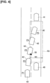
- the cut-in determination unit 25 can determine a cut-in of the other vehicle 42 even earlier as compared with the scenario shown in Figure 3 . Specifically, the cut-in determination unit 25 determines that the other vehicle 42 has cut in at position P4 in the scenario shown in Figure 3 , whereas the cut-in determination unit 25 determines that the other vehicle 42 has cut in at position P3 in the scenario shown in Figure 4 .
- a process carried out when a cut-in of the other vehicle 42 is detected in the scenarios shown in Figures 2-4 will be described next. If a cut-in of the other vehicle 42 is detected, the controller 20 issues a warning to the user riding in the host vehicle 40, decelerates the host vehicle 40, or the like. Alternatively, the controller 20 may cancel the following control.
- the warning may be by means of voice or a display on a monitor.
- determining that the other vehicle 42 has cut in is synonymous with detecting a cut-in of the other vehicle 42.
- the cut-in determination unit 25 determines cut-ins by means of a different method than one used when the host vehicle 40 is traveling. Specifically, when the host vehicle 40 is traveling, the cut-in determination unit 25 uses the area of the rear surface 50 of the other vehicle 42, whereas when the host vehicle 40 is stopped, the cut-in determination unit 25 uses the area of a side surface 60 of the other vehicle 42.
- P1-P4 in Figure 5 indicate the positions of the other vehicle 42. If the other vehicle 42 from position P1 cuts in between the host vehicle 40 and the preceding vehicle 41, the movement trajectory of the other vehicle 42 will be described by the curve indicated by positions P2 to P4.
- the curvature of the curve of Figure 5 is greater. This is because the inter-vehicular distance between the host vehicle 40 and the preceding vehicle 41 is relatively long during travel, and thus the angle at which the other vehicle 42 enters into the host vehicle's lane (the lane in which the host vehicle 40 is traveling) is small; whereas when the inter-vehicular distance is short during the stopped state, that the angle at which the other vehicle 42 enters into the host vehicle's lane is greater.
- the side surface 60 of the other vehicle 42 entering area R1 is more easily detected by the camera 10.
- the side surface 60 of the other vehicle 42 enters area R1 before the rear surface 50.
- a cut-in is determined using the area of the side surface 60 of the other vehicle 42. It is thus possible to detect a cut-in earlier as compared with the case in which a cut-in is determined using the rear surface 50. Because the side surface 60 is used when the host vehicle 40 is stopped, it is possible to reduce erroneous detection of the side surface of a vehicle that travels along an adjacent lane on a curve.
- An adjacent lane means a lane adjacent to the lane in which the host vehicle 40 travels.
- the cut-in determination unit 25 calculates the area of the side surface 60 acquired from the camera 10. If the area of the side surface 60 exceeds or equals a prescribed value, the cut-in determination unit 25 determines that the other vehicle 42 has cut in between the preceding vehicle 41 and the host vehicle 40.
- the side surface of a vehicle in the present embodiment is defined as a projected view of the vehicle as seen from side.
- the prescribed value (fourth prescribed value) used for comparison with the area of the side surface 60 may be the same value as the prescribed value (third prescribed value) used for comparison with the area of the rear surface 50 or a different value.
- the definition of the size of area R1 shown in Figure 5 is the same as the definition of the size of area R1 shown in Figure 2 .
- the size of area R1 is not limited that shown in Figure 5 .
- the width in the vehicle width direction may be the width W2 of the lane in which the host vehicle 40 is traveling.
- the cut-in determination unit 25 can determine a cut-in of the other vehicle 42 earlier as compared with the scenario shown in Figure 5 . Specifically, the cut-in determination unit 25 determines that the other vehicle 42 has cut in at position P4 in the scenario shown in Figure 5 , whereas the cut-in determination unit 25 determines that the other vehicle 42 has cut in at position P3 in the scenario shown in Figure 6 .
- the width in the vehicle width direction may be the width W3, which is greater than the width W2.
- the width W3 is set in consideration of a margin.
- the cut-in determination unit 25 can determine a cut-in of the other vehicle 42 even earlier as compared with the scenario shown in Figure 6 . Specifically, the cut-in determination unit 25 determines that the other vehicle 42 has cut in at position P3 in the scenario shown in Figure 6 , whereas the cut-in determination unit 25 determines that the other vehicle 42 has cut in at position P2 in the scenario shown in Figure 7 .
- the following travel unit 23 prohibits a following start even if the user inputs a following start instruction. In this case, because the user cannot use the following start system, it is necessary for the user to manually start the host vehicle 40. It is thereby possible to start the host vehicle 40 after the user has checked the area ahead.
- the following travel unit 23 may issue a warning to the user when a following start is prohibited.
- the following travel unit 23 automatically starts the host vehicle 40 in accordance with the user's following start instruction.
- Step S101 the stop determination unit 24 uses the speed of the host vehicle 40 measured by the vehicle speed sensor 13 in order to determine whether the host vehicle 40 has stopped. If the speed of the host vehicle 40 is 0 km/h (YES is Step S101), the process proceeds to Step S103. When the speed of the host vehicle 40 is not 0 km/h (NO in Step S101), the process proceeds to Step S109.
- Step S103 the cut-in determination unit 25 calculates the area of the side surface 60 of the other vehicle 42 acquired from the camera 10. If the area of the side surface 60 exceeds or equals a prescribed value (YES in Step S103), the cut-in determination unit 25 determines that the other vehicle 42 has cut in between the host vehicle 40 and the preceding vehicle 41. The process then proceeds to Step S107, and the following travel unit 23 prohibits a following start. If, on the other hand, the area of the side surface 60 is smaller than the prescribed value (NO in Step S103), the cut-in determination unit 25 determines that a cut-in has not taken place. The process then proceeds to Step S105, and the following travel unit 23 automatically starts the host vehicle 40.
- Step S109 the cut-in determination unit 25 calculates the area of the rear surface 50 of the other vehicle 42 acquired from the camera 10. If the area of the rear surface 50 exceeds or equals a prescribed value (YES in Step S109), the cut-in determination unit 25 determines that the other vehicle 42 has cut in between the host vehicle 40 and the preceding vehicle 41. The process then proceeds to Step S113, and the controller 20 issues a warning to the user, decelerates the host vehicle 40, or the like. If, on the other hand, the area of the rear surface 50 is smaller than the prescribed value (NO in Step S109), the cut-in determination unit 25 determines that a cut-in has not taken place. The process then proceeds to Step S111, and the following travel unit 23 causes the host vehicle 40 to follow the preceding vehicle 41.
- the controller 20 sets the detection field (areas R1-R3) of a sensor (camera 10) for detecting another vehicle 42 between the host vehicle 40 and the preceding vehicle 41. If the host vehicle 40 is traveling and following the preceding vehicle 41 and the area of the rear surface 50 of the other vehicle 42 detected within the detection field exceeds or equals a prescribed value, the controller 20 determines that the other vehicle 42 has cut in between the preceding vehicle 41 and the host vehicle 40. The detection field is set between the host vehicle 40 and the preceding vehicle 41.
- the controller 20 determines that the other vehicle 42 has cut in between the preceding vehicle 41 and the host vehicle 40.
- the side surface 60 of the other vehicle 42 entering the detection field is more easily detected by the camera 10.
- the side surface 60 of the other vehicle 42 enters the detection field before the rear surface 50.
- the controller 20 may determine whether the host vehicle 40 is on an automobiles-only road based on location information of the host vehicle 40.
- An automobiles-only road is defined in Japan as a road dedicated for the exclusive use of automobiles on which only those automobiles designated by the road administrator are allowed to drive.
- a representative automobiles-only road is an expressway.
- the cut-in determination unit 25 may determine a cut-in only when it is determined that the host vehicle 40 is on an automobiles-only road. By determining cut-ins only on straight roads or curved roads of limited curvature, such as automobiles-only roads, erroneous cut-in determinations can be prevented.
- the controller 20 issues a warning to the user, decelerates the host vehicle 40, or the like. If a cut-in of the other vehicle 42 is detected when the host vehicle 40 is stopped, the following travel unit 23 prohibits the host vehicle 40 from starting and following the preceding vehicle 41.
- a cut-in can be quickly detected, sudden braking is reduced. In addition, it is possible to prevent a following start.
- the cut-in determination unit 25 may determine the presence or absence of a cut-in based on changes in the rear surface of the preceding vehicle 41 captured in a camera image. If the other vehicle 42 cuts in, part of the rear surface of the preceding vehicle 41 is obscured by the other vehicle 42 as seen by the camera 10. As a result, a change in the image of the rear surface of the preceding vehicle 41 occurs. If a change in the image of the rear surface of the preceding vehicle 41 occurs, the cut-in determination unit 25 may determine that the other vehicle 42 has cut in between the preceding vehicle 41 and the host vehicle 40.
- the cut-in determination unit 25 may determine that the other vehicle 42 has cut in between the preceding vehicle 41 and the host vehicle 40.
- the distance from the front end of the other vehicle 42 to the host vehicle 40 means the shortest distance between the host vehicle 40 and the bumper of the other vehicle 42.
- the prescribed value (fifth prescribed value) referred to here is different than the prescribed value (fourth prescribed value) that was used in comparisons with the side surface 60.
- the cut-in determination unit 25 may determine a cut-in of the other vehicle 42 in accordance with the degree of entry of the other vehicle 42 into the detection field of the camera 10.
- the degree of entry into the detection field is defined as the area of overlap of the other vehicle 42 with the detection field.
- the area of overlap of the other vehicle 42 with the detection field is defined as the area of overlap of the other vehicle 42 as seen directly overhead.
- the cut-in determination unit 25 determines that the other vehicle 42 has cut in front of the host vehicle 40. In addition, if the host vehicle 40 is stopped and it is determined that the degree of entry of the other vehicle 42 into the detection field exceeds or equals a second prescribed value that is smaller than the first prescribed value, the cut-in determination unit 25 determines that the other vehicle 42 has cut in front of the host vehicle 40. Specific examples will be described with reference to Figures 2 and 5 .
- the degree of entry of the other vehicle 42 into the detection field (area R1) at position P5 in Figure 2 is about 50% of the total area as seen from above. And the degree of entry of the other vehicle 42 into the detection field (area R1) at position P4 in Figure 5 is approximately 10% of the total area as seen from above.
- the cut-in determination unit 25 determines that the other vehicle 42 has cut in front of the host vehicle 40.
- the cut-in determination unit 25 determines that the other vehicle 42 has cut in front of the host vehicle 40.
- the numerical values of 50% and 10% described above are merely examples, and no limitation thereto is implied. As long as the condition that the second prescribed value is smaller than the first prescribed value is satisfied, the numerical values of the first prescribed value and the second prescribed value may be any value.
- Modified Example 2 it becomes possible to detect the other vehicle 42 that may cut in front of the host vehicle 40 when the host vehicle 40 is stopped.
- the threshold value for determining a cut-in of the other vehicle 42 is smaller when the host vehicle 40 is stopped as opposed to when the host vehicle 40 is traveling. That is, because the second prescribed value is smaller than the first prescribed value, a cut-in can be more quickly detected when the host vehicle 40 is stopped as opposed to when the host vehicle 40 is traveling. Setting the second prescribed value smaller than the first prescribed value is similarly applied in the above-described embodiment, Modified Example 1, and Modified Example 3 described further below.
- the controller 20 sets the first prescribed value to the third prescribed value, which is the area of the rear surface of the other vehicle 42 detected with the detection field, and sets the second prescribed value to the fourth prescribed value, which is the area of the side surface of the other vehicle 42 detected within the detection field.
- the length of area R1 was described as the distance in the direction of travel from the front end of the host vehicle 40 to the rear end of the preceding vehicle 41.
- the length of area R1 is not limited thereto.
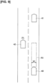
- the length of area R1 may be a distance in the direction of travel that does not reach the rear end of the preceding vehicle 41.
- the length of area R1 is preferably greater than the distance in the direction of travel over which an emergency brake is applied by the autonomous driving function. It thus becomes possible to detect a cut-in before the emergency brake is applied.
- the method for determining a cut-in when area R1 is as shown in Figure 9 will now be described.
- the scenario shown in Figure 10 depicts the scenario of Figure 9 at a subsequent time.
- the host vehicle 40 is traveling.
- the cut-in determination unit 25 determines that the other vehicle 42 has cut in front of the host vehicle 40.
- the area of the rear surface of the other vehicle 42 detected within area R1 means the area of overlap of the other vehicle 42 with area R1, as described in Modified Example 2.
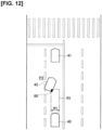
- the length of area R1 in the direction of travel when the host vehicle 40 is stopped also may be a length that does not reach the rear end of the preceding vehicle 41, in the same manner as in Figure 9 .
- the length of area R1 in the direction of travel is preferably greater than the distance over which the emergency brake is applied by the autonomous driving function.
- the cut-in determination unit 25 determines that the other vehicle 42 has cut in front of the host vehicle 40.
- the area of the rear surface of the other vehicle 42 detected within area R1 means the area of overlap of the other vehicle 42 with area R1, as described in Modified Example 2.
- the threshold value for determining a cut-in of the other vehicle 42 is smaller when the host vehicle 40 is stopped as opposed to when the host vehicle 40 is traveling. That is, because the seventh prescribed value is smaller than the sixth prescribed value, a cut-in can be detected more quickly when the host vehicle 40 is stopped as opposed to when the host vehicle 40 is traveling.
- the processing circuits include programmed processing devices, such as processing devices including electronic circuits. Moreover, the processing circuits include devices such as circuit components and application-specific integrated circuits (ASIC) arranged to execute the described functions.
- ASIC application-specific integrated circuits
- the controller 20 may set the detection field of the camera 10 using virtual lane markings based on past detection results.
- the lane width of the virtual lane markings may be the vehicle width of the host vehicle 40, obtained by adding a margin to the vehicle width of the host vehicle 40, or may be a width in accordance with the road type.
- the cut-in determination unit 25 may determine a cut-in based on the area of the side surface of the other vehicle 42. For example, when the host vehicle 40 is traveling and it is determined that the area of the side surface of the other vehicle 42 that overlaps in the detection field exceeds or equals a prescribed value (eighth prescribed value), it may be determined that the other vehicle 42 has cut in front of the host vehicle 40. In addition, when the host vehicle 40 is stopped and the area of the side surface of the other vehicle 42 that overlaps the detection field exceeds or equals a ninth prescribed value that is smaller than the eighth prescribed value, the cut-in determination unit 25 may determine that the other vehicle 42 has cut in front of the host vehicle 40. As a result, it is possible to detect a cut-in more quickly when the host vehicle 40 is stopped as opposed to when the host vehicle 40 is traveling.
- the present example can be applied irrespective of the presence or absence of preceding vehicle 41. That is, the driving assist device according to the present example can detect another vehicle that cuts in front of the host vehicle 40 in a lane in which the host vehicle 40 is traveling irrespective of the presence or absence of preceding vehicle 41.
Landscapes
- Engineering & Computer Science (AREA)
- Transportation (AREA)
- Mechanical Engineering (AREA)
- Automation & Control Theory (AREA)
- Chemical & Material Sciences (AREA)
- Combustion & Propulsion (AREA)
- Traffic Control Systems (AREA)
- Control Of Driving Devices And Active Controlling Of Vehicle (AREA)
Claims (5)
- Procédé d'aide à la conduite au moyen d'un contrôleur utilisant un capteur pour détecter un autre véhicule (42) se rabattant devant un véhicule hôte (40) dans une voie où circule le véhicule hôte (40), comprenant :le réglage, par le contrôleur, d'une plage de détection (R1) du capteur devant le véhicule hôte (40),caractérisé parla détermination, par le contrôleur, que l'autre véhicule (42) s'est rabattu devant le véhicule hôte (40) lorsque le véhicule hôte (40) se déplace et qu'un degré de pénétration de l'autre véhicule (42) dans la plage de détection (R1) est supérieur ou égal à une première valeur prescrite, etla détermination, par le contrôleur, que l'autre véhicule (42) s'est rabattu devant le véhicule hôte (40) lorsque le véhicule hôte (40) est arrêté et que le degré est supérieur ou égal à une deuxième valeur prescrite, inférieure à la première valeur prescrite ;où le contrôleurcommande au véhicule hôte (40) de suivre un véhicule précédent (41) se trouvant devant le véhicule hôte (40),règle la plage de détection (R1) du capteur entre le véhicule hôte (40) et le véhicule précédent (41),règle la première valeur prescrite à une troisième valeur prescrite, laquelle est une zone d'une surface arrière (50) de l'autre véhicule (42) détectée à l'intérieur de la plage de détection (R1), etrègle la deuxième valeur prescrite à une quatrième valeur prescrite, laquelle est une zone d'une surface latérale (60) de l'autre véhicule (42) détectée à l'intérieur de la plage de détection (R1).
- Procédé d'aide à la conduite selon la revendication 1, où la longueur de la plage de détection (R1) dans la direction de déplacement du véhicule hôte (40) est supérieure à la distance sur laquelle un freinage d'urgence est exécuté par une fonction de conduite autonome.
- Procédé d'aide à la conduite selon la revendication 1 ou la revendication 2, comprenantl'acquisition d'informations de localisation du véhicule hôte (40),la détermination si le véhicule hôte (40) se trouve sur une route réservée aux automobiles sur la base des informations de localisation, etla détection exclusive de l'autre véhicule (42) se rabattant devant le véhicule hôte (40) après avoir déterminé que le véhicule hôte (40) se trouve sur la route réservée aux automobiles.
- Procédé d'aide à la conduite selon l'une des revendications 1 à 3, comprenant l'empêchement du véhicule hôte (40) à démarrer et à suivre le véhicule précédent si le rabattement est détecté et que le véhicule hôte (40) est arrêté.
- Dispositif d'aide à la conduite configuré pour détecter un autre véhicule (42) se rabattant devant un véhicule hôte (40) dans une voie où circule le véhicule hôte (40), comprenant :un capteur configuré pour détecter l'autre véhicule (42) devant le véhicule hôte (40) ; etun contrôleur configuré pour définir une plage de détection (R1) du capteur,caractérisé en ce quele contrôleur est en outre configuré pourdéterminer que l'autre véhicule (42) s'est rabattu devant le véhicule hôte (40) lorsque le véhicule hôte (40) se déplace et qu'un degré de pénétration de l'autre véhicule (42) dans la plage de détection (R1) est supérieur ou égal à une première valeur prescrite, etdéterminer que l'autre véhicule (42) s'est rabattu devant le véhicule hôte (40) lorsque le véhicule hôte (40) est arrêté et que le degré est supérieur ou égal à une deuxième valeur prescrite, inférieure à la première valeur prescrite ;où le contrôleur est en outre configuré pour :commander au véhicule hôte (40) de suivre un véhicule précédent (41) se trouvant devant le véhicule hôte (40),régler la plage de détection (R1) du capteur entre le véhicule hôte (40) et le véhicule précédent (41),régler la première valeur prescrite à une troisième valeur prescrite, laquelle est une zone d'une surface arrière (50) de l'autre véhicule (42) détectée à l'intérieur de la plage de détection (R1), etrégler la deuxième valeur prescrite à une quatrième valeur prescrite, laquelle est une zone d'une surface latérale (60) de l'autre véhicule (42) détectée à l'intérieur de la plage de détection (R1).
Applications Claiming Priority (1)
| Application Number | Priority Date | Filing Date | Title |
|---|---|---|---|
| PCT/JP2020/032625 WO2022044266A1 (fr) | 2020-08-28 | 2020-08-28 | Procédé d'aide à la conduite et dispositif d'aide à la conduite |
Publications (3)
| Publication Number | Publication Date |
|---|---|
| EP4206054A1 EP4206054A1 (fr) | 2023-07-05 |
| EP4206054A4 EP4206054A4 (fr) | 2024-01-03 |
| EP4206054B1 true EP4206054B1 (fr) | 2025-01-29 |
Family
ID=80352936
Family Applications (1)
| Application Number | Title | Priority Date | Filing Date |
|---|---|---|---|
| EP20946539.2A Active EP4206054B1 (fr) | 2020-08-28 | 2020-08-28 | Procédé d'aide à la conduite et dispositif d'aide à la conduite |
Country Status (5)
| Country | Link |
|---|---|
| US (1) | US12157467B2 (fr) |
| EP (1) | EP4206054B1 (fr) |
| JP (1) | JP7425420B2 (fr) |
| CN (1) | CN114514155B (fr) |
| WO (1) | WO2022044266A1 (fr) |
Families Citing this family (3)
| Publication number | Priority date | Publication date | Assignee | Title |
|---|---|---|---|---|
| KR20220056922A (ko) * | 2020-10-28 | 2022-05-09 | 현대자동차주식회사 | 자율주행 제어 장치 및 방법 |
| KR20220078772A (ko) * | 2020-12-03 | 2022-06-13 | 현대모비스 주식회사 | 차량의 교차로 주행 제어 시스템 및 방법 |
| JP2025090139A (ja) * | 2023-12-05 | 2025-06-17 | トヨタ自動車株式会社 | 追従走行制御装置、追従走行制御方法及びプログラム |
Family Cites Families (26)
| Publication number | Priority date | Publication date | Assignee | Title |
|---|---|---|---|---|
| JP3602337B2 (ja) | 1998-05-15 | 2004-12-15 | 株式会社日立製作所 | 車両走行制御装置 |
| JP4104233B2 (ja) | 1998-12-03 | 2008-06-18 | 株式会社日立製作所 | 走行環境認識装置 |
| JP3942991B2 (ja) | 2002-08-28 | 2007-07-11 | 本田技研工業株式会社 | 車両の追従走行装置 |
| JP2005231490A (ja) * | 2004-02-19 | 2005-09-02 | Honda Motor Co Ltd | 追従走行制御装置 |
| JP2008117073A (ja) * | 2006-11-01 | 2008-05-22 | Fuji Heavy Ind Ltd | 割り込み車両検出装置 |
| JP2010038731A (ja) | 2008-08-05 | 2010-02-18 | Fujitsu Ten Ltd | レーダ装置 |
| JP5969220B2 (ja) * | 2012-02-28 | 2016-08-17 | 株式会社日本自動車部品総合研究所 | 車間距離制御装置 |
| US8990001B2 (en) * | 2013-07-26 | 2015-03-24 | Nissan North America, Inc. | Vehicle collision monitoring method |
| JP6507525B2 (ja) | 2014-08-22 | 2019-05-08 | 株式会社アドヴィックス | 車両制御装置 |
| US9746550B2 (en) * | 2014-10-08 | 2017-08-29 | Ford Global Technologies, Llc | Detecting low-speed close-range vehicle cut-in |
| JP6520177B2 (ja) * | 2015-02-10 | 2019-05-29 | 株式会社デンソー | 運転制御装置、運転制御方法 |
| KR101921874B1 (ko) | 2015-07-14 | 2018-11-23 | 닛산 지도우샤 가부시키가이샤 | 발진 제어 장치 및 발진 제어 방법 |
| JP2017083950A (ja) * | 2015-10-23 | 2017-05-18 | 三菱自動車工業株式会社 | 運転支援システム |
| WO2018135869A1 (fr) * | 2017-01-19 | 2018-07-26 | 주식회사 만도 | Système de caméra pour système d'aide à la conduite intelligent, et système et procédé d'aide à la conduite |
| US10787172B2 (en) * | 2017-05-19 | 2020-09-29 | Nissan Motor Co., Ltd. | Driving assistance device and driving assistance method |
| EP3690856B1 (fr) * | 2017-09-26 | 2024-07-17 | Nissan Motor Co., Ltd. | Procédé et appareil d'aide à la conduite |
| JP6580115B2 (ja) * | 2017-12-18 | 2019-09-25 | 本田技研工業株式会社 | 自動運転車両の走行制御装置 |
| JP7021983B2 (ja) * | 2018-03-07 | 2022-02-17 | 本田技研工業株式会社 | 車両制御装置、車両制御方法、およびプログラム |
| JP7134649B2 (ja) * | 2018-03-08 | 2022-09-12 | 東芝デジタルソリューションズ株式会社 | 隊列走行運用システムおよび隊列走行運用方法 |
| JP7182376B2 (ja) * | 2018-05-14 | 2022-12-02 | 日産自動車株式会社 | 運転支援方法及び運転支援装置 |
| US20200114921A1 (en) * | 2018-10-11 | 2020-04-16 | Ford Global Technologies, Llc | Sensor-limited lane changing |
| JP7135931B2 (ja) * | 2019-02-22 | 2022-09-13 | スズキ株式会社 | 車両の走行制御装置 |
| KR102758772B1 (ko) * | 2019-12-20 | 2025-01-22 | 주식회사 에이치엘클레무브 | 차량 및 그 제어 방법 |
| US11385642B2 (en) * | 2020-02-27 | 2022-07-12 | Zoox, Inc. | Perpendicular cut-in training |
| JP7509491B2 (ja) * | 2020-06-11 | 2024-07-02 | 株式会社Subaru | 車両用運転支援装置 |
| JP7276282B2 (ja) * | 2020-08-24 | 2023-05-18 | トヨタ自動車株式会社 | 物体検出装置、物体検出方法及び物体検出用コンピュータプログラム |
-
2020
- 2020-08-28 US US17/632,250 patent/US12157467B2/en active Active
- 2020-08-28 JP JP2022500910A patent/JP7425420B2/ja active Active
- 2020-08-28 WO PCT/JP2020/032625 patent/WO2022044266A1/fr not_active Ceased
- 2020-08-28 CN CN202080055089.5A patent/CN114514155B/zh active Active
- 2020-08-28 EP EP20946539.2A patent/EP4206054B1/fr active Active
Also Published As
| Publication number | Publication date |
|---|---|
| JP7425420B2 (ja) | 2024-01-31 |
| WO2022044266A1 (fr) | 2022-03-03 |
| US12157467B2 (en) | 2024-12-03 |
| JPWO2022044266A1 (fr) | 2022-03-03 |
| EP4206054A4 (fr) | 2024-01-03 |
| CN114514155B (zh) | 2025-03-18 |
| US20220266830A1 (en) | 2022-08-25 |
| CN114514155A (zh) | 2022-05-17 |
| EP4206054A1 (fr) | 2023-07-05 |
Similar Documents
| Publication | Publication Date | Title |
|---|---|---|
| CN108778880B (zh) | 车辆控制装置、车辆控制方法及存储介质 | |
| US7388513B2 (en) | Driving state determining system | |
| US11608062B2 (en) | Vehicle control method and vehicle control device | |
| US20190071071A1 (en) | Vehicle control device, vehicle control method, and storage medium | |
| JP7119428B2 (ja) | 運転支援装置 | |
| CN112384419B (zh) | 车辆的驾驶辅助控制装置、车辆的驾驶辅助系统以及车辆的驾驶辅助控制方法 | |
| US12036978B2 (en) | Driving assistance method and driving assistance device | |
| KR20190056977A (ko) | 차량 제어 장치 | |
| EP4206054B1 (fr) | Procédé d'aide à la conduite et dispositif d'aide à la conduite | |
| JP2012226635A (ja) | 車両の衝突予防安全装置 | |
| US20200385023A1 (en) | Vehicle control apparatus, vehicle, operation method of vehicle control apparatus, and non-transitory computer-readable storage medium | |
| US20200384992A1 (en) | Vehicle control apparatus, vehicle, operation method of vehicle control apparatus, and non-transitory computer-readable storage medium | |
| EP4212400B1 (fr) | Procédé d'aide à la conduite et dispositif d'aide à la conduite | |
| JP7038610B2 (ja) | 運転支援方法及び運転支援装置 | |
| US11260884B2 (en) | Vehicle control apparatus, vehicle, operation method of vehicle control apparatus, and non-transitory computer-readable storage medium | |
| US20240239314A1 (en) | Vehicle control apparatus | |
| US11865999B2 (en) | Vehicle seatbelt device, tension control method, and storage medium | |
| US12344248B2 (en) | Method and device for controlling vehicle acceleration on a curved road using curve information | |
| RU2803100C1 (ru) | Способ помощи при вождении и устройство помощи при вождении | |
| JP7755237B2 (ja) | 車両の制御装置、制御方法及び、プログラム | |
| JP7516232B2 (ja) | 車両の走行制御方法及び走行制御装置 | |
| CN118043247A (zh) | 车辆控制装置 |
Legal Events
| Date | Code | Title | Description |
|---|---|---|---|
| STAA | Information on the status of an ep patent application or granted ep patent |
Free format text: STATUS: UNKNOWN |
|
| STAA | Information on the status of an ep patent application or granted ep patent |
Free format text: STATUS: THE INTERNATIONAL PUBLICATION HAS BEEN MADE |
|
| PUAI | Public reference made under article 153(3) epc to a published international application that has entered the european phase |
Free format text: ORIGINAL CODE: 0009012 |
|
| STAA | Information on the status of an ep patent application or granted ep patent |
Free format text: STATUS: REQUEST FOR EXAMINATION WAS MADE |
|
| 17P | Request for examination filed |
Effective date: 20220203 |
|
| AK | Designated contracting states |
Kind code of ref document: A1 Designated state(s): AL AT BE BG CH CY CZ DE DK EE ES FI FR GB GR HR HU IE IS IT LI LT LU LV MC MK MT NL NO PL PT RO RS SE SI SK SM TR |
|
| DAV | Request for validation of the european patent (deleted) | ||
| DAX | Request for extension of the european patent (deleted) | ||
| A4 | Supplementary search report drawn up and despatched |
Effective date: 20231205 |
|
| RIC1 | Information provided on ipc code assigned before grant |
Ipc: B60W 30/18 20120101ALI20231129BHEP Ipc: B60W 10/20 20060101ALI20231129BHEP Ipc: B60W 10/184 20120101ALI20231129BHEP Ipc: B60W 10/06 20060101ALI20231129BHEP Ipc: B60W 30/17 20200101ALI20231129BHEP Ipc: B60W 30/14 20060101ALI20231129BHEP Ipc: B60W 40/08 20120101AFI20231129BHEP |
|
| GRAP | Despatch of communication of intention to grant a patent |
Free format text: ORIGINAL CODE: EPIDOSNIGR1 |
|
| STAA | Information on the status of an ep patent application or granted ep patent |
Free format text: STATUS: GRANT OF PATENT IS INTENDED |
|
| INTG | Intention to grant announced |
Effective date: 20241031 |
|
| GRAS | Grant fee paid |
Free format text: ORIGINAL CODE: EPIDOSNIGR3 |
|
| GRAA | (expected) grant |
Free format text: ORIGINAL CODE: 0009210 |
|
| STAA | Information on the status of an ep patent application or granted ep patent |
Free format text: STATUS: THE PATENT HAS BEEN GRANTED |
|
| AK | Designated contracting states |
Kind code of ref document: B1 Designated state(s): AL AT BE BG CH CY CZ DE DK EE ES FI FR GB GR HR HU IE IS IT LI LT LU LV MC MK MT NL NO PL PT RO RS SE SI SK SM TR |
|
| REG | Reference to a national code |
Ref country code: GB Ref legal event code: FG4D |
|
| REG | Reference to a national code |
Ref country code: CH Ref legal event code: EP |
|
| REG | Reference to a national code |
Ref country code: DE Ref legal event code: R096 Ref document number: 602020045693 Country of ref document: DE |
|
| REG | Reference to a national code |
Ref country code: IE Ref legal event code: FG4D |
|
| REG | Reference to a national code |
Ref country code: NL Ref legal event code: MP Effective date: 20250129 |
|
| PG25 | Lapsed in a contracting state [announced via postgrant information from national office to epo] |
Ref country code: NL Free format text: LAPSE BECAUSE OF FAILURE TO SUBMIT A TRANSLATION OF THE DESCRIPTION OR TO PAY THE FEE WITHIN THE PRESCRIBED TIME-LIMIT Effective date: 20250129 |
|
| PG25 | Lapsed in a contracting state [announced via postgrant information from national office to epo] |
Ref country code: RS Free format text: LAPSE BECAUSE OF FAILURE TO SUBMIT A TRANSLATION OF THE DESCRIPTION OR TO PAY THE FEE WITHIN THE PRESCRIBED TIME-LIMIT Effective date: 20250429 |
|
| PG25 | Lapsed in a contracting state [announced via postgrant information from national office to epo] |
Ref country code: FI Free format text: LAPSE BECAUSE OF FAILURE TO SUBMIT A TRANSLATION OF THE DESCRIPTION OR TO PAY THE FEE WITHIN THE PRESCRIBED TIME-LIMIT Effective date: 20250129 |
|
| PG25 | Lapsed in a contracting state [announced via postgrant information from national office to epo] |
Ref country code: PL Free format text: LAPSE BECAUSE OF FAILURE TO SUBMIT A TRANSLATION OF THE DESCRIPTION OR TO PAY THE FEE WITHIN THE PRESCRIBED TIME-LIMIT Effective date: 20250129 |
|
| PG25 | Lapsed in a contracting state [announced via postgrant information from national office to epo] |
Ref country code: ES Free format text: LAPSE BECAUSE OF FAILURE TO SUBMIT A TRANSLATION OF THE DESCRIPTION OR TO PAY THE FEE WITHIN THE PRESCRIBED TIME-LIMIT Effective date: 20250129 |
|
| REG | Reference to a national code |
Ref country code: LT Ref legal event code: MG9D |
|
| PG25 | Lapsed in a contracting state [announced via postgrant information from national office to epo] |
Ref country code: IS Free format text: LAPSE BECAUSE OF FAILURE TO SUBMIT A TRANSLATION OF THE DESCRIPTION OR TO PAY THE FEE WITHIN THE PRESCRIBED TIME-LIMIT Effective date: 20250529 Ref country code: NO Free format text: LAPSE BECAUSE OF FAILURE TO SUBMIT A TRANSLATION OF THE DESCRIPTION OR TO PAY THE FEE WITHIN THE PRESCRIBED TIME-LIMIT Effective date: 20250429 |
|
| REG | Reference to a national code |
Ref country code: AT Ref legal event code: MK05 Ref document number: 1763184 Country of ref document: AT Kind code of ref document: T Effective date: 20250129 |
|
| PG25 | Lapsed in a contracting state [announced via postgrant information from national office to epo] |
Ref country code: HR Free format text: LAPSE BECAUSE OF FAILURE TO SUBMIT A TRANSLATION OF THE DESCRIPTION OR TO PAY THE FEE WITHIN THE PRESCRIBED TIME-LIMIT Effective date: 20250129 |
|
| PG25 | Lapsed in a contracting state [announced via postgrant information from national office to epo] |
Ref country code: LV Free format text: LAPSE BECAUSE OF FAILURE TO SUBMIT A TRANSLATION OF THE DESCRIPTION OR TO PAY THE FEE WITHIN THE PRESCRIBED TIME-LIMIT Effective date: 20250129 Ref country code: PT Free format text: LAPSE BECAUSE OF FAILURE TO SUBMIT A TRANSLATION OF THE DESCRIPTION OR TO PAY THE FEE WITHIN THE PRESCRIBED TIME-LIMIT Effective date: 20250529 |
|
| PG25 | Lapsed in a contracting state [announced via postgrant information from national office to epo] |
Ref country code: BG Free format text: LAPSE BECAUSE OF FAILURE TO SUBMIT A TRANSLATION OF THE DESCRIPTION OR TO PAY THE FEE WITHIN THE PRESCRIBED TIME-LIMIT Effective date: 20250129 Ref country code: GR Free format text: LAPSE BECAUSE OF FAILURE TO SUBMIT A TRANSLATION OF THE DESCRIPTION OR TO PAY THE FEE WITHIN THE PRESCRIBED TIME-LIMIT Effective date: 20250430 |
|
| PG25 | Lapsed in a contracting state [announced via postgrant information from national office to epo] |
Ref country code: AT Free format text: LAPSE BECAUSE OF FAILURE TO SUBMIT A TRANSLATION OF THE DESCRIPTION OR TO PAY THE FEE WITHIN THE PRESCRIBED TIME-LIMIT Effective date: 20250129 |
|
| PG25 | Lapsed in a contracting state [announced via postgrant information from national office to epo] |
Ref country code: SE Free format text: LAPSE BECAUSE OF FAILURE TO SUBMIT A TRANSLATION OF THE DESCRIPTION OR TO PAY THE FEE WITHIN THE PRESCRIBED TIME-LIMIT Effective date: 20250129 |
|
| PG25 | Lapsed in a contracting state [announced via postgrant information from national office to epo] |
Ref country code: SM Free format text: LAPSE BECAUSE OF FAILURE TO SUBMIT A TRANSLATION OF THE DESCRIPTION OR TO PAY THE FEE WITHIN THE PRESCRIBED TIME-LIMIT Effective date: 20250129 |
|
| PG25 | Lapsed in a contracting state [announced via postgrant information from national office to epo] |
Ref country code: DK Free format text: LAPSE BECAUSE OF FAILURE TO SUBMIT A TRANSLATION OF THE DESCRIPTION OR TO PAY THE FEE WITHIN THE PRESCRIBED TIME-LIMIT Effective date: 20250129 |
|
| PGFP | Annual fee paid to national office [announced via postgrant information from national office to epo] |
Ref country code: DE Payment date: 20250724 Year of fee payment: 6 |
|
| PG25 | Lapsed in a contracting state [announced via postgrant information from national office to epo] |
Ref country code: IT Free format text: LAPSE BECAUSE OF FAILURE TO SUBMIT A TRANSLATION OF THE DESCRIPTION OR TO PAY THE FEE WITHIN THE PRESCRIBED TIME-LIMIT Effective date: 20250129 |
|
| PGFP | Annual fee paid to national office [announced via postgrant information from national office to epo] |
Ref country code: GB Payment date: 20250724 Year of fee payment: 6 |
|
| PGFP | Annual fee paid to national office [announced via postgrant information from national office to epo] |
Ref country code: FR Payment date: 20250725 Year of fee payment: 6 |
|
| PG25 | Lapsed in a contracting state [announced via postgrant information from national office to epo] |
Ref country code: EE Free format text: LAPSE BECAUSE OF FAILURE TO SUBMIT A TRANSLATION OF THE DESCRIPTION OR TO PAY THE FEE WITHIN THE PRESCRIBED TIME-LIMIT Effective date: 20250129 Ref country code: CZ Free format text: LAPSE BECAUSE OF FAILURE TO SUBMIT A TRANSLATION OF THE DESCRIPTION OR TO PAY THE FEE WITHIN THE PRESCRIBED TIME-LIMIT Effective date: 20250129 |
|
| PG25 | Lapsed in a contracting state [announced via postgrant information from national office to epo] |
Ref country code: RO Free format text: LAPSE BECAUSE OF FAILURE TO SUBMIT A TRANSLATION OF THE DESCRIPTION OR TO PAY THE FEE WITHIN THE PRESCRIBED TIME-LIMIT Effective date: 20250129 |
|
| PG25 | Lapsed in a contracting state [announced via postgrant information from national office to epo] |
Ref country code: SK Free format text: LAPSE BECAUSE OF FAILURE TO SUBMIT A TRANSLATION OF THE DESCRIPTION OR TO PAY THE FEE WITHIN THE PRESCRIBED TIME-LIMIT Effective date: 20250129 |
|
| REG | Reference to a national code |
Ref country code: DE Ref legal event code: R097 Ref document number: 602020045693 Country of ref document: DE |
|
| PLBE | No opposition filed within time limit |
Free format text: ORIGINAL CODE: 0009261 |
|
| STAA | Information on the status of an ep patent application or granted ep patent |
Free format text: STATUS: NO OPPOSITION FILED WITHIN TIME LIMIT |
|
| REG | Reference to a national code |
Ref country code: CH Ref legal event code: L10 Free format text: ST27 STATUS EVENT CODE: U-0-0-L10-L00 (AS PROVIDED BY THE NATIONAL OFFICE) Effective date: 20251210 |
|
| 26N | No opposition filed |
Effective date: 20251030 |
|
| REG | Reference to a national code |
Ref country code: CH Ref legal event code: H13 Free format text: ST27 STATUS EVENT CODE: U-0-0-H10-H13 (AS PROVIDED BY THE NATIONAL OFFICE) Effective date: 20260324 |
|
| PG25 | Lapsed in a contracting state [announced via postgrant information from national office to epo] |
Ref country code: MC Free format text: LAPSE BECAUSE OF FAILURE TO SUBMIT A TRANSLATION OF THE DESCRIPTION OR TO PAY THE FEE WITHIN THE PRESCRIBED TIME-LIMIT Effective date: 20250129 |
|
| PG25 | Lapsed in a contracting state [announced via postgrant information from national office to epo] |
Ref country code: LU Free format text: LAPSE BECAUSE OF NON-PAYMENT OF DUE FEES Effective date: 20250828 |
|
| PG25 | Lapsed in a contracting state [announced via postgrant information from national office to epo] |
Ref country code: CH Free format text: LAPSE BECAUSE OF NON-PAYMENT OF DUE FEES Effective date: 20250831 |