EP4073318B1 - Maschine und verfahren zum stabilisieren eines schottergleises - Google Patents
Maschine und verfahren zum stabilisieren eines schottergleises Download PDFInfo
- Publication number
- EP4073318B1 EP4073318B1 EP20808036.6A EP20808036A EP4073318B1 EP 4073318 B1 EP4073318 B1 EP 4073318B1 EP 20808036 A EP20808036 A EP 20808036A EP 4073318 B1 EP4073318 B1 EP 4073318B1
- Authority
- EP
- European Patent Office
- Prior art keywords
- track
- load
- stabilising
- machine
- stabilization
- Prior art date
- Legal status (The legal status is an assumption and is not a legal conclusion. Google has not performed a legal analysis and makes no representation as to the accuracy of the status listed.)
- Active
Links
Images



Classifications
-
- E—FIXED CONSTRUCTIONS
- E01—CONSTRUCTION OF ROADS, RAILWAYS, OR BRIDGES
- E01B—PERMANENT WAY; PERMANENT-WAY TOOLS; MACHINES FOR MAKING RAILWAYS OF ALL KINDS
- E01B27/00—Placing, renewing, working, cleaning, or taking-up the ballast, with or without concurrent work on the track; Devices therefor; Packing sleepers
- E01B27/12—Packing sleepers, with or without concurrent work on the track; Compacting track-carrying ballast
- E01B27/20—Compacting the material of the track-carrying ballastway, e.g. by vibrating the track, by surface vibrators
-
- E—FIXED CONSTRUCTIONS
- E01—CONSTRUCTION OF ROADS, RAILWAYS, OR BRIDGES
- E01B—PERMANENT WAY; PERMANENT-WAY TOOLS; MACHINES FOR MAKING RAILWAYS OF ALL KINDS
- E01B27/00—Placing, renewing, working, cleaning, or taking-up the ballast, with or without concurrent work on the track; Devices therefor; Packing sleepers
- E01B27/12—Packing sleepers, with or without concurrent work on the track; Compacting track-carrying ballast
- E01B27/13—Packing sleepers, with or without concurrent work on the track
- E01B27/16—Sleeper-tamping machines
Definitions
- the invention relates to a machine for stabilizing a track with a ballast bed, comprising a machine frame supported on rail chassis and a stabilization unit which can be rolled on rails of the track by means of aggregate rollers and which comprises a vibration exciter for generating a dynamic impact force and a loading device for generating a load acting on the track.
- the invention also relates to a method for carrying out a stabilization process using the machine.
- tracks with ballast bedding are regularly processed using a tamping machine.
- the tamping machine moves along the track and lifts the track grate made up of sleepers and rails to an over-corrected target position using a lifting/straightening unit.
- the new track position is fixed by tamping the track using a tamping unit.
- a sufficient and, above all, uniform load-bearing capacity of the track ballast is an essential prerequisite for the stability of the track position in railway operations.
- a machine is used to stabilize the track after a tamping process.
- the track is subjected to a static load and is caused to vibrate locally.
- the vibration causes the grains in the grain structure to become mobile, allow themselves to be moved and move into a denser storage location.
- the resulting ballast compaction increases the load-bearing capacity of the track and anticipates track settlement due to compaction.
- the increase in transverse displacement resistance also goes hand in hand with compaction.
- a corresponding method is disclosed.
- the GB 2 250 765 A discloses a track stabilizer for correcting elevation errors. To adjust track lowering, the load acting on the track is controlled proportionally to the elevation errors.
- Machines for stabilizing a track are already known several times from the prior art.
- a so-called dynamic track stabilizer stabilization units located between two rail chassis are pressed onto the track to be stabilized using loading devices with a vertical load.
- a transverse vibration of the stabilization units is transmitted to the track via aggregate rollers with continuous right-of-way.
- a corresponding machine is, for example, from the WO 2019/158288 A1 known.
- the stabilization unit includes a vibration exciter which has at least two unbalance masses driven with a variably adjustable phase shift. Thanks to the variably adjustable phase shift, the impact force acting on the track can be specifically changed.
- the stabilization unit is supported against a machine frame using hydraulic load drives with constant force.
- the disclosed stabilization unit includes a vibration exciter that generates an adjustable vibration. This causes a track grate to vibrate, with the resulting deflection of the track grate being recorded.
- the vibration generated is adapted to the detected deflection.
- a vertical contact force is applied to the stabilization unit using hydraulic cylinders.
- the EP 2 902 546 A1 discloses a stabilization unit with a vibration drive for generating horizontal vibrations.
- the vibration is generated by a cylinder vibrator.
- hydraulic adjusting cylinders can be designed to be vibration-excitable to generate a load.
- the invention is based on the object of improving a machine of the type mentioned in such a way that the compaction success of the track ballast is increased and that additional information is obtained for a work-integrated compaction control for an assessment of the track condition. A corresponding procedure should also be specified.
- the loading device for periodically changing the load during a stabilization process is coupled to a control device which is set up to coordinate an interval of the periodically changed load with an oscillation frequency of the vibration exciter.
- the frequency of the periodic change in the load is significantly lower than the oscillation frequency of the vibration exciter.
- the resulting increase in compaction success is due to soil mechanics. With new track ballast, so-called ballast flow occurs under dynamic load. In this state, the gravel grains of the grain structure rearrange themselves and move into denser storage. By periodically increasing the load, the flow of ballast in the load application area is locally prevented, so that the compaction effect temporarily becomes more widespread. Due to the periodic change in the load, the short and long range of the load application are alternately influenced. This leads to improved compaction success compared to a constant load. With a constant load, the ballast flow leads to an increased dynamic decoupling between dynamic excitation and the long-range area of load introduction.
- a significant advantage of the invention is evident in ballast compaction with changing ballast and subsoil properties, because the load, which according to the invention periodically fluctuates, even with changing Conditions lead to optimal compaction success.
- the invention shows significant improvements in ballast compaction, particularly with old and dirty track ballast where no ballast flow occurs.
- sensors are arranged to record a course of a force acting on the track from the stabilization unit, with measurement signals from the sensors being fed to an evaluation device and the evaluation device being set up to determine a parameter derived from the force curve.
- the stabilization unit and the ballast track form a dynamic interaction system, the state of movement of which provides information about the properties of the condition of the track ballast.
- a work-integrated dynamic compaction control and an assessment of the track condition are carried out, with the targeted variation of the process parameters providing additional information.
- the additional load significantly influences the friction between the sleeper sole and the track ballast.
- a further improvement provides that a control loop with a controller, an adjusting device for the loading device and a measuring device for recording the process parameter is set up to regulate a process parameter.
- the regulation of at least one process parameter enables automatic adaptation of the stabilization process to changed conditions in the dynamic interaction system stabilization unit-track grate-track ballast.
- An advantageous extension provides that a further stabilization unit is arranged, with a further loading device, which is coupled to the control device in order to generate a periodically changed load. This makes it possible to operate both stabilization units in a coordinated manner in order to achieve better compaction success.
- the track caused to oscillate by means of the stabilization unit, a periodically changing load being exerted on the track by means of the loading device during the stabilization process.
- a course of a force acting on the track by the stabilization unit is recorded using sensors, with measurement signals from the sensors being evaluated by means of an evaluation device to determine a parameter derived from the force course.
- an oscillation frequency coordinated with an interval of the periodically changed load is specified for the vibration exciter.
- the oscillation frequency of the oscillation exciter is at least a power of ten higher than the frequency of the periodically changed load.
- At least two stabilization units arranged one behind the other, each with their own loading device, are operated together.
- Each loading device can achieve its own course of the load acting on the track.
- Two favorable operating modes provide that the two loading devices are operated synchronously or asynchronously, so that both stabilization units exert the same load on the track in synchronous operation and different loads on the track in asynchronous operation. Synchronous operation is preferred for in-process compression control.
- the advantage of asynchronous operation lies in the constant load on the machine frame, because both stabilization units are not supported at the same time with the same reaction force against the machine frame.
- the method is improved with several stabilization units by specifying an interval that is coordinated with the travel speed of the machine for the periodically changed load. It makes sense that the interval of the pulsating load is coordinated with the driving speed so that those areas that are processed by the leading stabilization unit with the lowest load are processed by the trailing stabilization unit with the highest load and vice versa.
- the interval of the pulsating load is selected such that the area of influence of the stabilizer leads to overlaps (not changing too slowly), but the speed of the load change still allows stationary oscillation states in the dynamic track stabilization (not changing too quickly).
- the machine according to the invention can be used either as an independent stabilization machine 1 ( Fig. 1 ) or as a combined machine with a tamping machine 2 ( Fig. 2 ) and a stabilization machine 1 coupled to it.
- an independent stabilization machine 1 it has its own travel drive 3 and its own driver's cab 4.
- the machine 1 includes a machine frame 5, which can be moved on rail chassis 6 on a track 7.
- Track 7 is a ballast track with a track grate stored in a ballast bed 8.
- the track grate consists of sleepers 9 and rails 10 attached to them. To correct the track position, the track grate is raised into a new position using a lifting/straightening unit 11 of the tamping machine 2. The track grate is fixed in the new position by tamping the track ballast under the sleepers 9 using a tamping unit 12.
- the stabilization machine 1 is used so that the new track position remains stable after processing and the transverse displacement resistance of the track 7 reaches the required level again after maintenance.
- This is also known as a dynamic track stabilizer (DGS).
- DGS dynamic track stabilizer
- the aim is to bring the track ballast, which has been partially loosened by tamping the track 7, into a stable, denser position through optimal subsequent compaction using the stabilization machine 1.
- Stabilization machine 1 shown includes two stabilization units 13 arranged one behind the other with unit rollers 14 for holding the rails 10. In a simple embodiment, only one stabilization unit 13 is arranged. During operation, the respective stabilization unit 13 is caused to vibrate in the transverse direction of the track by means of a vibration exciter 15. The aggregate rollers 14 transmit the vibration to the track grate, whereby the track 7 is dynamically stimulated. The track ballast vibrates in an area of influence 16 of the stabilization unit 13, which leads to compaction of the ballast.
- the vibration frequency of the vibration exciter 15 is usually in the range of 33-42 Hz.
- the stabilization machine 1 includes a machine control 17. This is optionally coupled to a machine control 17 of the tamping machine 2.
- both the tamping machine 2 and the stabilization machine 1 include a chord measuring system 18 for determining the track position.
- the loading facility 19 includes, for example, two hydraulic cylinders which are articulated on both sides of the longitudinal beams of the machine frame 5.
- the associated stabilization unit 13 is pressed against the track 7 with a vertical load F (vertical load).
- this load F changes periodically during a stabilization process.
- This targeted imposition of a cyclical fluctuation increases the compaction success compared to a stabilization process with static vertical loading.
- the loading device 19 is coupled to a control device 20.
- a control program is set up in the control device 20 that specifies a periodically changed manipulated variable for the loading device 19.
- the control device 20 is advantageously connected to the machine control 19 or integrated into it in order to coordinate the driving speed v of the stabilization machine 1 and the periodic change in the load F.
- the frequency of the periodically changed load F is, for example, 1 Hz and is therefore significantly below the oscillation frequency of 33-42 Hz of the vibration exciter 15.
- a time interval i is considered for a load cycle of the surcharge F.
- This interval i of the periodically changed surcharge F must be coordinated with a distance a between the two stabilization units 13, the operating mode (synchronous or asynchronous) and a driving speed v of the stabilization machine 1. Specifically, at each point where the leading stabilization unit 13 was loaded with the maximum load F, the trailing stabilization unit 13 should be loaded with the minimum load F and vice versa.
- all stabilization units 13 are cyclically loaded with the same load F.
- the stabilization units 13, the track grate and the underlying track ballast thereby form a common dynamic interaction system. This makes it easier to interpret the measurement results as part of the work-integrated dynamic compaction control.
- the alternating stress on the machine frame 5 can be undesirable. In asynchronous operation, this alternating stress is eliminated because a total force of both stabilization units 13 on the machine frame 5 remains constant. Only the load F is cyclically redistributed between the two stabilization units 13, so that the load on one is accompanied by the relief on the other stabilization unit 13. One stabilization unit 13 then reaches the maximum max of the load F when the other stabilization unit 13 experiences the minimum min of the load F.
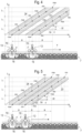
- the Figures 3-6 represent the load relations in a uniform representation.
- the spatial arrangement of the stabilization units 13 can be seen in the lower area.
- a time-distance diagram is arranged above each, which shows a path s traveled by the stabilization machine 1 over time t.
- Driving speed v is a direct correlation between the distance traveled s (location) of the respective stabilization unit 13 and the time t. Therefore the path s is plotted on the abscissa and the time t is plotted on the ordinate.
- ⁇ s ⁇ s / ⁇ t
- the formulated advantageous condition of different loads min, max at the same location applies in all operating modes.
- the longest interval i of the periodically changed load F at which this condition is fulfilled is the interval i which corresponds to the fundamental oscillation of the variable load F.
- the interval i is independent of the distance a between the stabilization units 13, the driving speed v and the operating mode (synchronous or asynchronous).
- the first harmonic is in Fig. 4 shown. It makes sense to choose a harmonic at low driving speed v and a large distance a between the stabilization units 13.
- a higher-frequency harmonic of the changing load F is advantageously selected ( Fig. 4 for synchronous operation).
- the 3rd harmonic i.e. the second harmonic
- n 3rd harmonic
- the Figures 7 and 8th represent the course of the load F over time.
- Fig. 8 For asynchronous operation shows Fig. 8 the course of the load F for one stabilization unit 13 with a solid line (load path 23) and for the other stabilization unit 13 with a dash-dotted line (load path 24).
- the fundamental oscillation n1 and the three first harmonics n2, n3, n4 are drawn one after the other in chronological order.
- Fig. 9 time the additional benefit of varying the surcharge F when applying work-integrated dynamic compaction control.
- the idea is shown as an example using the horizontal vibration amplitude y DGS of the stabilization unit 13. This changes depending on the load F.
- the horizontal vibration amplitude y DGS of the stabilization unit 13 represents all of the measurement and calculation variables described in the Austrian patent application A 331/2018 as well as additional measurements such as the vibrations in the environment (size and shape of wave propagation).
- the amplitude y DGS decreases in a first section 25.
- the amplitude y DGS increases again in a second section 26. Due to hysteresis, the two sections 25, 26 do not run on the same line. However, both sections 25, 26 have a recognizable kink 28 in a narrow load area 27, which represents an indication of a system change in the dynamic interaction system stabilization unit-track grate-track ballast.
- the position of this system change is an additional indicator of the ballast condition and correlates with the lateral displacement resistance of track 7. This indicator can also be used for automatic control of the process parameters.
Landscapes
- Engineering & Computer Science (AREA)
- Architecture (AREA)
- Civil Engineering (AREA)
- Structural Engineering (AREA)
- Machines For Laying And Maintaining Railways (AREA)
- Vibration Prevention Devices (AREA)
Description
- Die Erfindung betrifft eine Maschine zum Stabilisieren eines Gleises mit Schotterbett, umfassend einen auf Schienenfahrwerken abgestützten Maschinenrahmen und ein mittels Aggregatrollen auf Schienen des Gleises abrollbares Stabilisationsaggregat, das einen Schwingungserreger zur Erzeugung einer dynamischen Schlagkraft sowie eine Belastungseinrichtung zur Erzeugung einer auf das Gleis wirkenden Auflast umfasst. Zudem betrifft die Erfindung ein Verfahren zur Durchführung eines Stabilisierungsvorgangs mittels der Maschine.
- Zur Wiederherstellung bzw. Erhaltung einer vorgegebenen Gleislage werden Gleise mit Schotterbettung regelmäßig mittels einer Stopfmaschine bearbeitet. Dabei befährt die Stopfmaschine das Gleis und hebt den aus Schwellen und Schienen gebildeten Gleisrost mittels eines Hebe- /Richtaggregats auf eine überkorrigierte Sollposition. Eine Fixierung der neuen Gleislage erfolgt durch Stopfen des Gleises mittels eines Stopfaggregats. Dabei ist eine ausreichende und vor allem gleichmäßige Tragfähigkeit des Gleisschotters eine essenzielle Grundvoraussetzung für die Stabilität der Gleislage im Bahnbetrieb.
- In der Regel kommt deshalb nach einem Stopfvorgang eine Maschine zum Stabilisieren des Gleises zum Einsatz. Dabei wird das Gleis mit einer statischen Auflast belastet und lokal in Schwingung versetzt. Die Vibration führt dazu, dass die Körner im Korngerüst mobil werden, sich verschieben lassen und in eine dichtere Lagerung gehen. Die damit erreichte Schotterverdichtung erhöht die Tragfähigkeit des Gleises und nimmt verdichtungsbedingte Gleissetzungen vorweg. Auch die Erhöhung des Querverschiebewiderstands geht mit der Verdichtung einher. In der
EP 1 817 463 A1 ist ein entsprechendes Verfahren offenbart. - Die
GB 2 250 765 A - Maschinen zum Stabilisieren eines Gleises sind aus dem Stand der Technik bereits mehrfach bekannt. Bei einem sogenannten dynamischen Gleisstabilisator werden zwischen zwei Schienenfahrwerken befindliche Stabilisationsaggregate mittels Belastungseinrichtungen mit einer vertikalen Auflast auf das zu stabilisierende Gleis gedrückt. Über Aggregatrollen wird unter kontinuierlicher Vorfahrt eine Querschwingung der Stabilisationsaggregate auf das Gleis übertragen.
- Eine entsprechende Maschine ist beispielsweise aus der
WO 2019/158288 A1 bekannt. Dabei umfasst das Stabilisationsaggregat einen Schwingungserreger, der zumindest zwei mit einer variabel einstellbaren Phasenverschiebung angetriebene Unwuchtmassen aufweist. Durch die variabel einstellbare Phasenverschiebung ist die auf das Gleis einwirkende Schlagkraft gezielt veränderbar. Dabei ist das Stabilisationsaggregat mittels hydraulischer Belastungsantriebe mit konstanter Kraft gegen einen Maschinenrahmen abgestützt. - Ein in der
WO 2017/144152 A1 offenbartes Stabilisationsaggregat umfasst einen Schwingungserreger, der eine einstellbare Schwingung erzeugt. Damit wird ein Gleisrost in Schwingung versetzt, wobei die resultierende Auslenkung des Gleisrostes erfasst wird. Vorteilhafterweise erfolgt eine Anpassung der erzeugten Schwingung an die erfasste Auslenkung. Zudem wird mittels Hydraulikzylinder eine vertikale Anpresskraft auf das Stabilisationsaggregat aufgebracht. - In der
WO 2019/158288 A1 ist ein Stabilisationsaggregat mit einer veränderbaren Schlagkraft offenbart. Durch Höhenantriebe wird eine statische vertikale Auflast auf das Gleis aufgebracht. - Die
EP 2 902 546 A1 offenbart ein Stabilisationsaggregat mit einem Schwingungsantrieb zur Erzeugung horizontaler Schwingungen. Die Schwingungserzeugung erfolgt dabei durch einen Zylindervibrator. Zusätzlich können hydraulische Anstellzylinder zur Erzeugung einer Auflast schwingungserregbar ausgebildet sein. - Der Erfindung liegt die Aufgabe zugrunde, eine Maschine der eingangs genannten Art dahingehend zu verbessern, dass der Verdichtungserfolg des Gleisschotters gesteigert wird und dass zusätzlich Informationen für eine arbeitsintegrierte Verdichtungskontrolle für eine Beurteilung des Gleiszustandes gewonnen werden. Zudem soll ein entsprechendes Verfahren angegeben werden.
- Erfindungsgemäß werden diese Aufgaben gelöst durch die Merkmale der unabhängigen Ansprüche 1 und 5. Abhängige Ansprüche geben vorteilhafte Ausgestaltungen der Erfindung an.
- Dabei ist die Belastungseinrichtung zur periodischen Veränderung der Auflast während eines Stabilisierungsvorgangs mit einer Steuereinrichtung gekoppelt, die zur Abstimmung eines Intervalls der periodisch veränderten Auflast mit einer Schwingungsfrequenz des Schwingungserregers eingerichtet ist. Die Frequenz der periodischen Veränderung der Auflast ist dabei deutlich niedriger als die Schwingungsfrequenz des Schwingungserregers. Die damit erreichte Steigerung des Verdichtungserfolges ist bodenmechanisch bedingt. Bei neuem Gleisschotter tritt unter dynamischer Belastung sogenanntes Schotterfließen ein. In diesem Zustand lagern sich die Schotterkörner des Korngefüges um und begeben sich in dichtere Lagerung. Durch eine periodische Erhöhung der Auflast wird das Schotterfließen im Lasteinleitungsbereich lokal unterbunden, sodass die Verdichtungswirkung vorübergehend weitrechender wird. Durch die periodische Veränderung der Auflast werden abwechselnd Nah- und Fernbereich der Lasteinleitung beeinflusst. Das führt zum verbesserten Verdichtungserfolg im Vergleich zu einer konstanten Auflast. Bei einer konstanten Auflast führt das Schotterfließen nämlich zu einer vermehrt dynamischen Entkopplung zwischen dynamischer Anregung und dem Fernbereich der Lasteinleitung.
- Ein wesentlicher Vorteil der Erfindung zeigt sich bei der Schotterverdichtung mit wechselnden Schotter- und Untergrundeigenschaften, weil die erfindungsgemäß periodisch schwankende Auflast auch bei wechselnden Bedingungen zu einem optimalen Verdichtungserfolg führt. Insbesondere bei altem und verschmutztem Gleisschotter, bei dem kein Schotterfließen auftritt, zeigt die Erfindung erhebliche Verbesserungen der Schotterverdichtung.
- Bei einer vorteilhaften Weiterbildung der Erfindung sind Sensoren zur Erfassung eines Verlaufs einer vom Stabilisationsaggregat auf das Gleis wirkenden Kraft angeordnet, wobei Messsignale der Sensoren einer Auswerteeinrichtung zugeführt sind und wobei die Auswerteeinrichtung zur Ermittlung einer aus dem Kraftverlauf abgeleiteten Kenngröße eingerichtet ist. Dabei bilden Stabilisationsaggregat und Schottergleis ein dynamisches Interaktionssystem, dessen Bewegungszustand Auskunft über die Eigenschaften des Gleisschotterzustandes zulässt. Auf diese Weise erfolgt eine arbeitsintegrierte dynamische Verdichtungskontrolle und eine Beurteilung des Gleiszustandes, wobei die gezielte Variation der Prozessparameter zusätzliche Informationen liefert. Durch die Auflast wird die Reibung zwischen Schwellensohle und Gleisschotter wesentlich beeinflusst. In der Auswertung der prozessbegleitenden Verdichtungskontrolle kann somit klarer zwischen Schottersteifigkeit und Schotterzustand sowie Querverschiebewiderstand unterschieden werden.
- Eine weitere Verbesserung sieht vor, dass zum Regeln eines Prozessparameters ein Regelkreis mit einem Regler, einer Stelleinrichtung für die Belastungseinrichtung und einer Messeinrichtung zur Erfassung des Prozessparameters eingerichtet ist. Die Regelung zumindest eines Prozessparameters ermöglicht eine automatische Anpassung des Stabilisierungsvorgangs an geänderte Zustände im dynamischen Interaktionssystem Stabilisationsaggregat-Gleisrost-Gleisschotter.
- Eine vorteilhafte Erweiterung sieht vor, dass ein weiteres Stabilisationsaggregat angeordnet ist, mit einer weiteren Belastungseinrichtung, die zur Erzeugung einer periodisch veränderten Auflast mit der Steuereinrichtung gekoppelt ist. Damit ergibt sich die Möglichkeit, beide Stabilisationsaggregate aufeinander abgestimmt zu betreiben, um einen besseren Verdichtungserfolg zu erzielen.
- Beim erfindungsgemäßen Verfahren zur Durchführung eines Stabilisierungsvorgangs mittels der beschriebenen Maschine wird das Gleis mittels des Stabilisierungsaggregats in Schwingung versetzt, wobei während des Stabilisierungsvorgangs mittels der Belastungseinrichtung eine periodisch veränderte Auflast auf das Gleis ausgeübt wird.
- Zur dynamischen Verdichtungskontrolle und zur Beurteilung des Gleiszustandes ist es von Vorteil, wenn mittels Sensoren ein Verlauf einer vom Stabilisationsaggregat auf das Gleis wirkenden Kraft erfasst wird, wobei Messsignale der Sensoren mittels einer Auswerteeinrichtung zur Ermittlung einer aus dem Kraftverlauf abgeleiteten Kenngröße ausgewertet werden.
- Erfindungsgemäß ist auch vorgesehen, dass für den Schwingungserreger eine mit einem Intervall der periodisch veränderten Auflast abgestimmte Schwingungsfrequenz vorgegeben wird. Insbesondere bei mehreren hintereinander angeordneten Stabilisierungsaggregaten ist es sinnvoll, dabei auch die Fahrgeschwindigkeit zu berücksichtigen. Bei optimaler Abstimmung ist die Schwingungsfrequenz des Schwingungserregers zumindest um eine Zehnerpotenz höher als die Frequenz der periodisch veränderten Auflast.
- Vorteilhafterweise werden zumindest zwei hintereinander angeordnete Stabilisationsaggregate mit jeweils eigener Belastungseinrichtung gemeinsam betrieben. Dabei ist mit jeder Belastungseinrichtung ein eigener Verlauf der auf das Gleis wirkenden Auflast erzielbar.
- Zwei günstige Betriebsarten sehen vor, dass die beiden Belastungseinrichtungen synchron oder asynchron betrieben werden, sodass beide Stabilisationsaggregate im synchronen Betrieb dieselbe Auflast und im asynchronen Betrieb unterschiedliche Auflasten auf das Gleis ausüben. Für die prozessbegleitende Verdichtungskontrolle ist der synchrone Betrieb zu bevorzugen. Der Vorteil des asynchronen Betriebs liegt in einer konstanten Belastung des Maschinenrahmens, weil sich nicht beide Stabilisationsaggregate zur gleichen Zeit mit derselben Reaktionskraft gegenüber dem Maschinenrahmen abstützten.
- Verbessert wird das Verfahren mit mehreren Stabilisationsaggregaten dadurch, dass für die periodisch veränderte Auflast ein mit einer Fahrgeschwindigkeit der Maschine abgestimmtes Intervall vorgegeben wird. Sinnvollerweise ist das Intervall der pulsierenden Auflast so auf die Fahrgeschwindigkeit abgestimmt, dass jene Stellen, die vom vorlaufenden Stabilisationsaggregat mit der geringsten Auflast bearbeitet werden, vom nachlaufenden Stabilisationsaggregat mit der höchsten Auflast bearbeitet werden und umgekehrt.
- Diese Abstimmung ist sowohl für synchronen als auch für asynchronen Betrieb möglich. Innerhalb dieser Bandbreite wird das Intervall der pulsierenden Auflast dermaßen gewählt, dass der Einflussbereich des Stabilisators zu Überlappungen führt (nicht zu langsam wechselnd), jedoch die Geschwindigkeit des Lastwechsels noch stationäre Schwingungszustände in der dynamischen Gleisstabilisierung ermöglicht (nicht zu schnell wechselnd).
- Die Erfindung wird nachfolgend in beispielhafter Weise unter Bezugnahme auf die beigefügten Figuren erläutert. Es zeigen in schematischer Darstellung:
- Fig. 1
- Stabilisationsmaschine mit zwei Stabilisationsaggregaten;
- Fig. 2
- Stopfmaschine;
- Fig. 3
- Belastungspfad der Stabilisationsaggregate im Synchronbetrieb mit dem größten Belastungsintervall (Grundschwingung) im Weg-ZeitDiagramm mit der entsprechenden Anordnung der Stabilisationsaggregate;
- Fig. 4
- Belastungspfad der Stabilisationsaggregate im Synchronbetrieb mit dem zweitgrößten Belastungsintervall (erste Oberschwingung) im Weg-Zeit-Diagramm mit der entsprechenden Anordnung der Stabilisationsaggregate;
- Fig. 5
- Belastungspfad der Stabilisationsaggregate im Asynchronbetrieb mit dem größten Belastungsintervall (Grundschwingung) im Weg-Zeit-Diagramm mit der entsprechenden Anordnung der Stabilisationsaggregate;
- Fig. 6
- Belastungspfad der Stabilisationsaggregate im Asynchronbetrieb mit dem drittgrößten Belastungsintervall (zweite Oberschwingung) im Weg-Zeit-Diagramm mit der entsprechenden Anordnung der Stabilisationsaggregate;
- Fig. 7
- zeitliche Veränderung der Auflast beider Stabilisationsaggregate im Synchronbetrieb in Grund- und Oberwellen mit zugehöriger Weg-Darstellung bei konstanter Fahrgeschwindigkeit;
- Fig. 8
- zeitliche Veränderung der unterschiedlichen Auflast beider Stabilisationsaggregate im Asynchronbetrieb hintereinander dargestellt in Grundwelle und drei Oberwellen mit zugehöriger Weg-Darstellung bei konstanter Fahrgeschwindigkeit;
- Fig. 9
- Diagramm einer horizontalen Schwingungsamplitude eines Stabilisationsaggregats über der Auflast;
- Die erfindungsgemäße Maschine ist entweder als eigenständige Stabilisationsmaschine 1 (
Fig. 1 ) oder als kombinierte Maschine mit einer Stopfmaschine 2 (Fig. 2 ) und einer daran gekuppelten Stabilisationsmaschine 1 ausgebildet. Im Falle einer eigenständigen Stabilisationsmaschine 1 verfügt diese über einen eigenen Fahrantrieb 3 und einen eigenen Führerstand 4. Die Maschine 1 umfasst einen Maschinenrahmen 5, der auf Schienenfahrwerken 6 auf einem Gleis 7 verfahrbar ist. - Das Gleis 7 ist ein Schottergleis mit einem in einem Schotterbett 8 gelagertem Gleisrost. Der Gleisrost besteht dabei aus Schwellen 9 und darauf befestigten Schienen 10. Zur Korrektur der Gleislage wird mit einem Hebe-/Richtaggregat 11 der Stopfmaschine 2 der Gleisrost in eine neue Position angehoben. Die Fixierung des Gleisrostes in der neuen Position erfolgt durch Stopfen des Gleisschotters unter den Schwellen 9 mittels eines Stopfaggregats 12.
- Damit die neue Gleislage nach der Bearbeitung stabil erhalten bleibt und der Querverschiebewiderstand des Gleises 7 nach der Instandhaltung wieder das erforderliche Niveau erreicht, wird die Stabilisationsmaschine 1 eingesetzt. Diese wird auch als Dynamischer Gleisstabilisator (DGS) bezeichnet. Ziel ist es, den durch das Stopfen des Gleises 7 teilweise aufgelockerten Gleisschotter durch optimale nachlaufende Verdichtung mittels der Stabilisationsmaschine 1 in eine stabile dichtere Lage zu bringen.
- Die in
Fig. 1 dargestellte Stabilisationsmaschine 1 umfasst dazu zwei hintereinander angeordnete Stabilisationsaggregate 13 mit Aggregatrollen 14 zum Festhalten der Schienen 10. In einer einfachen Ausprägung ist lediglich ein Stabilisationsaggregat 13 angeordnet. Im Betrieb wird das jeweilige Stabilisationsaggregat 13 mittels eines Schwingungserregers 15 in Gleisquerrichtung in Schwingung versetzt. Die Aggregatrollen 14 übertragen die Schwingung auf den Gleisrost, wodurch das Gleis 7 dynamisch angeregt wird. Dabei vibriert der Gleisschotter in einem Einflussbereich 16 des Stabilisationsaggregats 13, was zu einer Verdichtung des Schotters führt. Die Schwingungsfrequenz des Schwingungserregers 15 liegt gewöhnlich im Bereich von 33-42 Hz. - Zur Steuerung der Stabilisationsaggregat 13 und des Fahrantriebs 3 umfasst die Stabilisationsmaschine 1 eine Maschinensteuerung 17. Diese ist gegebenenfalls mit einer Maschinensteuerung 17 der Stopfmaschine 2 gekoppelt. Zudem umfasst sowohl die Stopfmaschine 2 als auch die Stabilisationsmaschine 1 ein Sehnenmesssystem 18 zur Gleislagebestimmung.
- Gegenüber dem Maschinenrahmen 5 ist das jeweilige Stabilisationsaggregat 13 mit einer Belastungseinrichtung 19 abgestützt. Die Belastungseinrichtung 19 umfasst beispielsweise zwei Hydraulikzylinder, die beidseits an Längsträgern des Maschinenrahmens 5 angelenkt sind. Mittels der Belastungseinrichtung 19 wird das zugehörige Stabilisationsaggregat 13 mit einer vertikalen Auflast F (Vertikalbelastung) gegen das Gleis 7 gedrückt.
- Erfindungsgemäß erfolgt eine periodische Veränderung dieser Auflast F während eines Stabilisierungsvorgangs. Durch dieses gezielte Aufprägen einer zyklischen Schwankung erhöht sich der Verdichtungserfolg gegenüber einem Stabilisierungsvorgang mit statischer Vertikalbelastung. Dazu ist die Belastungseinrichtung 19 mit einer Steuereinrichtung 20 gekoppelt. Konkret ist in der Steuereinrichtung 20 ein Steuerungsprogramm eingerichtet, dass der Belastungseinrichtung 19 eine periodisch veränderte Stellgröße vorgibt. Vorteilhafterweise ist die Steuereinrichtung 20 mit der Maschinensteuerung 19 verbunden oder in diese integriert, um die Fahrgeschwindigkeit v der Stabilisationsmaschine 1 und die periodische Veränderung der Auflast F aufeinander abzustimmen. Die Frequenz der periodisch veränderten Auflast F beträgt zum Beispiel 1 Hz und liegt damit deutlich unter der Schwingungsfrequenz von 33-42 Hz des Schwingungserregers 15.
- Sinnvollerweise erfährt jeder bearbeitete Abschnitt des Gleises 7 die verschiedenen dynamischen Verhältnisse, welche bei minimaler Auflast F, bei maximaler Auflast Fund im dazwischenliegenden Übergangsbereich auftreten. Auf diese Weise werden alle günstigen bodendynamischen Effekte ausgenützt. Betrachtet wird ein Zeitintervall i für einen Lastzyklus der Auflast F. Dieses Intervall i der periodisch veränderten Auflast F muss mit einem Abstand a der beiden Stabilisationsaggregate 13, der Betriebsweise (synchron oder asynchron) und einer Fahrgeschwindigkeit v der Stabilisationsmaschine 1 abgestimmt sein. Konkret soll an jeder Stelle, an der das vorlaufenden Stabilisationsaggregat 13 mit maximaler Auflast F belastet wurde, das nachlaufenden Stabilisationsaggregat 13 mit der minimalen Auflast F belastet werden und umgekehrt.
- Dabei ist der in den
Figuren 3-8 eingezeichnete verdichtbare Einflussbereich 16 zu berücksichtigen. Einerseits soll es zu keinen Lücken in der optimalen Verdichtung kommen (zu langes Intervall i), andererseits würde ein zu rascher Lastwechsel erwünschte stationäre Schwingungszustände der dynamischen Horizontal-Vibration verhindern (zu kurzes Intervall i). - Stationäre Schwingungszustände sind wichtig, um erfolgreich die arbeitsintegrierte Verdichtungskontrolle anwenden zu können. Mit der erfindungsgemäßen Lastvariation werden die Verdichtungskontrolle und die Beurteilung des Gleiszustandes mit zusätzlichen Möglichkeiten erweitert. Details der Kenngrößenermittlung zur Verdichtungskontrolle und zur Beurteilung des Gleiszustandes gehen aus der österreichischen Patentanmeldung A 331/2018 hervor. Dabei sind am Stabilisationsaggregat 13 Sensoren 21 zur Erfassung von Messsignalen und eine Auswerteeinrichtung 22 zur Kenngrößenermittlung angeordnet.
- Im Synchronbetrieb werden alle Stabilisationsaggregate 13 zyklisch mit derselben Last F belastet. Die Stabilisationsaggregate 13, der Gleisrost und der darunterliegende Gleisschotter bilden dadurch ein gemeinsames dynamisches Interaktionssystem. Das erleichtert die Interpretation der Messergebnisse im Rahmen der arbeitsintegrierten dynamischen Verdichtungskontrolle.
- Unerwünscht kann jedoch die Wechselbeanspruchung des Maschinenrahmens 5 sein. Beim Asynchronbetrieb fällt diese Wechselbeanspruchung weg, weil eine Gesamtkraft beider Stabilisationsaggregate 13 auf den Maschinenrahmen 5 konstant bleibt. Es wird lediglich die Last F zyklisch zwischen den beiden Stabilisationsaggregaten 13 umverteilt, sodass die Belastung des einen mit der Entlastung des anderen Stabilisationsaggregats 13 einhergeht. Das eine Stabilisationsaggregat 13 erreicht dann das Maximum max der Auflast F, wenn das andere Stabilisationsaggregat 13 das Minimum min der Auflast F erfährt.
- Die
Figuren 3-6 stellen in einheitlicher Darstellung die Belastungsrelationen dar. Im unteren Bereich ist die räumliche Anordnung der Stabilisationsaggregate 13 ersichtlich. Darüber ist jeweils ein Zeit-Weg-Diagramm angeordnet, das einen von der Stabilisationsmaschine 1 zurückgelegten Weg s über der Zeit t zeigt. Bei konstanter Fahrgeschwindigkeit v ist eine unmittelbare Korrelation zwischen dem zurückgelegten Weg s (Ort) des jeweiligen Stabilisationsaggregates 13 und der Zeit t gegeben. Deshalb sind der Weg s auf der Abszisse und die Zeit t auf der Ordinate aufgetragen. Dabei gilt mit einem Wegintervall Δs und mit einem Zeitintervall Δt folgender Zusammenhang für die Geschwindigkeit v:
- Im jeweiligen Diagramm ist erkennbar, zu welcher Zeit t sich die Stabilisationsaggregate 13 an welchem Ort aufhalten. Zudem sind Minimalbelastungen min (minimale Auflast F) und Maximalbelastungen max (maximale Auflast F) entlang eines Belastungspfads 23 des vorderen Stabilisationsaggregats 13 und entlang eines Belastungspfads 24 des hinteren Stabilisationsaggregats 13 mit Zeit t und Weg s (Ort) eingezeichnet. Damit kann die vorteilhafte Bedingung vollzogen werden, dass an jenen Orten, wo das vordere Stabilisationsaggregat 13 eine Maximalbelastung max erfahrt, das hintere Stabilisationsaggregat 13 eine Minimalbelastung min aufweist, und umgekehrt.
- Wenn die Stabilisationsaggregate 13 im Synchronbetrieb arbeiten (
Figuren 3 und4 ), tritt die Maximalbelastung max beider Stabilisationsaggregate 13 zum selben Zeitpunkt ein. Dasselbe gilt für die Minimalbelastung min. Im Asynchronbetrieb weist an einem Zeitpunkt mit Maximalbelastung max des einen Stabilisationsaggregats 13 das andere Stabilisationsaggregat 13 eine Minimalbelastung min auf (Figuren 5 und6 ). - In allen Betriebsarten gilt die formulierte vorteilhafte Bedingung der unterschiedlichen Belastungen min, max am selben Ort. Das längste Intervall i der periodisch veränderten Auflast F, bei dem diese Bedingung erfüllt ist, ist jenes Intervall i, welches der Grundschwingung der variablen Auflast F entspricht. Das Intervall i ist unabhängig vom Abstand a der Stabilisationsaggregate 13, der Fahrgeschwindigkeit v und der Betriebsart (synchron oder asynchron).
- Entsprechend der Darstellung in
Fig. 3 ergibt sich im Synchronbetrieb für das Intervall i0 der Grundschwingung mit dem Abstand a zwischen den Stabilisationsaggregaten 13 und der Fahrgeschwindigkeit v der Stabilisationsmaschine 1 folgender Zusammenhang:
- Für das jeweilige Intervall in der Oberschwingungen im Belastungspfad 23, 24 des jeweiligen Stabilisationsaggregats 13 gilt im Synchronbetrieb folgende Formel:

- Die erste Oberschwingung ist in
Fig. 4 dargestellt. Sinnvoll ist die Wahl einer Oberschwingung bei geringer Fahrgeschwindigkeit v und großem Abstand a zwischen den Stabilisationsaggregaten 13. - Im Asynchronbetrieb ergibt sich folgender Zusammenhang für das Intervall i1 der Grundschwingung (
Fig. 5 ):
- Allgemein gilt für das jeweilige Intervall in im Asynchronbetrieb folgende Formel im Belastungspfad 23, 24 der beiden Stabilisationsaggregate:

- Bei einem großen Abstand a der Stabilisationsaggregate 13 mit einer Lücke zwischen den einzelnen Einflussbereichen 16 wird vorteilhafterweise eine höherfrequente Oberschwingung der sich ändernden Auflast F gewählt (
Fig. 4 für Synchronbetrieb). - Auch bei sehr geringen Geschwindigkeiten v kann die Wahl einer höherfrequenten Oberschwingung der Auflast F sinnvoll sein. In
Fig. 6 ist für den Asynchronbetrieb exemplarisch die 3. Harmonische, das heißt die zweite Oberschwingung dargestellt (n=3). - Die
Figuren 7 und8 stellen den zeitlichen Verlauf der Auflast F dar. Die geometrische Beziehung der Stabilisationsaggregate 13 ist für konstante Fahrgeschwindigkeit v darunter dargestellt, mit folgendem Zusammenhang:
-
Fig. 7 zeigt die Grundschwingung für den Synchronbetrieb als durchgezogene Linie, mit dem entsprechenden Intervall i0 = 2·a/v. Die erste Oberwelle ist mit einer strichpunktierten Linie dargestellt, mit kürzerem Intervall i1 = (2·a/v) / 3 - Die zweite Oberschwingung ist mit einer gestrichelten Linie dargestellt, mit dem Intervall i2 = (2·a/v) / 5
- Für den Asynchronbetrieb zeigt
Fig. 8 den Verlauf der Auflast F für das eine Stabilisationsaggregats 13 mit durchgezogener Linie (Belastungspfad 23) und für das andere Stabilisationsaggregat 13 mit strichpunktierter Linie (Belastungspfad 24). Die Grundschwingung n1 und die drei ersten Oberschwingungen n2, n3, n4 sind in zeitlicher Abfolge hintereinander gezeichnet. Für das jeweilige Intervall i1, i2, i3, i4 gilt wieder:
-
Fig. 9 zeit den zusätzlichen Nutzen der Variation der Auflast F bei der Anwendung der arbeitsintegrierten dynamischen Verdichtungskontrolle. Exemplarisch wird die Idee anhand der horizontalen Schwingungsamplitude yDGS des Stabilisationsaggregats 13 gezeigt. Diese ändert sich in Abhängigkeit der Auflast F. Die horizontale Schwingungsamplitude yDGS des Stabilisationsaggregats 13 steht stellvertretend für sämtliche in der österreichischen Patentanmeldung A 331/2018 beschriebenen Mess- und Rechengrößen sowie zusätzliche Messungen wie die Vibrationen im Umfeld (Größe und Form der Wellenausbreitung). - Mit zunehmender Auflast F nimmt die Amplitude yDGS in einem ersten Abschnitt 25 ab. Bei der nachfolgenden Entlastung nimmt die Amplitude yDGS in einem zweiten Abschnitt 26 wieder zu. Aufgrund einer Hysterese verlaufen die beiden Abschnitte 25, 26 nicht auf derselben Linie. Beide Abschnitte 25, 26 weisen jedoch in einem schmalen Auflastbereich 27 einen erkennbaren Knick 28 auf, der einen Hinweis auf einen Systemwechsel im dynamischen Interaktionssystem Stabilisationsaggregat-Gleisrost-Gleisschotter darstellt. Die Lage dieses Systemwechsels ist ein zusätzlicher Indikator für den Schotterzustand und korreliert mit dem Querverschiebewiderstand des Gleises 7. Dieser Indikator kann auch zur automatischen Regelung der Prozessparameter herangezogen werden.
Claims (9)
- Maschine zum Stabilisieren eines Gleises (7) mit Schotterbett (8), umfassend einen auf Schienenfahrwerken (6) abgestützten Maschinenrahmen (5) und ein mittels Aggregatrollen (14) auf Schienen (10) des Gleises (7) abrollbares Stabilisationsaggregat (13), das einen Schwingungserreger (15) zur Erzeugung einer dynamischen Schlagkraft sowie eine Belastungseinrichtung (19) zur Erzeugung einer auf das Gleis (7) wirkenden Auflast (F) umfasst, dadurch gekennzeichnet, dass die Belastungseinrichtung (19) zur periodischen Veränderung der Auflast (F) während eines Stabilisierungsvorgangs mit einer Steuereinrichtung (20) gekoppelt ist, die zur Abstimmung eines Intervalls (i) der periodisch veränderten Auflast (F) mit einer Schwingungsfrequenz des Schwingungserregers (15) eingerichtet ist.
- Maschine nach Anspruch 1, dadurch gekennzeichnet, dass Sensoren (21) zur Erfassung eines Verlaufs einer vom Stabilisationsaggregat (13) auf das Gleis (7) wirkenden Kraft (F) angeordnet sind, dass Messsignale der Sensoren (21) einer Auswerteeinrichtung (22) zugeführt sind und dass die Auswerteeinrichtung (22) zur Ermittlung einer aus dem Kraftverlauf abgeleiteten Kenngröße eingerichtet ist.
- Maschine nach Anspruch 1 oder 2, dadurch gekennzeichnet, dass zum Regeln eines Prozessparameters ein Regelkreis mit einem Regler, einer Stelleinrichtung für die Belastungseinrichtung (19) und einer Messeinrichtung zur Erfassung des Prozessparameters eingerichtet ist.
- Maschine nach einem der Ansprüche 1 bis 3, dadurch gekennzeichnet, dass ein weiteres Stabilisationsaggregat (13) angeordnet ist, mit einer weiteren Belastungseinrichtung (19), die zur Erzeugung einer periodisch veränderten Auflast (F) mit der Steuereinrichtung (20) gekoppelt ist.
- Verfahren zur Durchführung eines Stabilisierungsvorgangs mittels einer Maschine nach einem der Ansprüche 1 bis 4, wobei das Gleis (7) mittels des Stabilisationsaggregats (13) in Schwingung versetzt wird, dadurch gekennzeichnet, dass während des Stabilisierungsvorgangs mittels der Belastungseinrichtung (19) mit einem Interfall (i) eine periodisch veränderte Auflast (F) auf das Gleis (7) ausgeübt wird und dass für den Schwingungserreger (15) eine mit dem Intervall (i) der periodisch veränderten Auflast (F) abgestimmte Schwingungsfrequenz vorgegeben wird.
- Verfahren nach Anspruch 5, dadurch gekennzeichnet, dass mittels Sensoren (21) ein Verlauf einer vom Stabilisationsaggregat (13) auf das Gleis (7) wirkenden Kraft erfasst wird und dass Messsignale der Sensoren (21) mittels einer Auswerteeinrichtung (22) zur Ermittlung einer aus dem Kraftverlauf abgeleiteten Kenngröße ausgewertet werden.
- Verfahren nach Anspruch 5 oder 6, dadurch gekennzeichnet, dass zwei hintereinander angeordnete Stabilisationsaggregate (13) mit jeweils eigener Belastungseinrichtung (19) gemeinsam betrieben werden.
- Verfahren nach Anspruch 7, dadurch gekennzeichnet, dass die beiden Belastungseinrichtungen (19) synchron oder asynchron betrieben werden, sodass beide Stabilisationsaggregate (13) im synchronen Betrieb dieselbe Auflast (F) und im asynchronen Betrieb unterschiedliche Auflasten (F) auf das Gleis ausüben.
- Verfahren nach Anspruch 7 oder 8, dadurch gekennzeichnet, dass für die periodisch veränderte Auflast (F) ein mit einer Fahrgeschwindigkeit (v) der Maschine abgestimmtes Intervall (i) vorgegeben wird.
Applications Claiming Priority (2)
| Application Number | Priority Date | Filing Date | Title |
|---|---|---|---|
| ATA390/2019A AT523228B1 (de) | 2019-12-10 | 2019-12-10 | Maschine und Verfahren zum Stabilisieren eines Schottergleises |
| PCT/EP2020/081990 WO2021115722A1 (de) | 2019-12-10 | 2020-11-13 | Maschine und verfahren zum stabilisieren eines schottergleises |
Publications (3)
| Publication Number | Publication Date |
|---|---|
| EP4073318A1 EP4073318A1 (de) | 2022-10-19 |
| EP4073318C0 EP4073318C0 (de) | 2024-01-10 |
| EP4073318B1 true EP4073318B1 (de) | 2024-01-10 |
Family
ID=73455674
Family Applications (1)
| Application Number | Title | Priority Date | Filing Date |
|---|---|---|---|
| EP20808036.6A Active EP4073318B1 (de) | 2019-12-10 | 2020-11-13 | Maschine und verfahren zum stabilisieren eines schottergleises |
Country Status (6)
| Country | Link |
|---|---|
| US (1) | US12559889B2 (de) |
| EP (1) | EP4073318B1 (de) |
| JP (1) | JP7665625B2 (de) |
| AT (1) | AT523228B1 (de) |
| ES (1) | ES2977280T3 (de) |
| WO (1) | WO2021115722A1 (de) |
Families Citing this family (2)
| Publication number | Priority date | Publication date | Assignee | Title |
|---|---|---|---|---|
| AT523034A3 (de) * | 2019-09-18 | 2024-02-15 | Plasser & Theurer Export Von Bahnbaumaschinen Gmbh | Maschine und Verfahren zum Stabilisieren eines Gleises |
| AT18149U1 (de) * | 2022-09-06 | 2024-03-15 | Plasser & Theurer Export Von Bahnbaumaschinen Gmbh | Verfahren und Vorrichtung zum Bestimmen der Beschaffenheit, insbesondere des Verdichtungsgrads, eines Gleisbetts |
Family Cites Families (14)
| Publication number | Priority date | Publication date | Assignee | Title |
|---|---|---|---|---|
| AT343165B (de) * | 1975-01-31 | 1978-05-10 | Plasser Bahnbaumasch Franz | Fahrbare schotterbett-verdichtmaschine zur korrektur der gleislage |
| AT370154B (de) * | 1981-03-09 | 1983-03-10 | Plasser Bahnbaumasch Franz | Gleisstopfmaschine mit voll a-synchronem stopfaggregat |
| AT401398B (de) * | 1990-02-06 | 1996-08-26 | Plasser Bahnbaumasch Franz | Kontinuierlich verfahrbare gleisbaumaschine zum verdichten der schotterbettung |
| AT400162B (de) * | 1990-02-06 | 1995-10-25 | Plasser Bahnbaumasch Franz | Verfahren und gleisbaumaschine zur messung des querverschiebewiderstandes |
| GB2250765B (en) * | 1990-02-06 | 1994-04-20 | Plasser Bahnbaumasch Franz | Process for consolidating railway track ballast |
| EP0726360B1 (de) * | 1995-02-09 | 1999-02-24 | Franz Plasser Bahnbaumaschinen-Industriegesellschaft m.b.H. | Verfahren und Maschine zum Unterstopfen und Stabilisieren eines Gleises |
| DK0952254T3 (da) * | 1998-03-27 | 2004-03-15 | Plasser Bahnbaumasch Franz | Fremgangsmåde til sporpositionskorrektion |
| PL1817463T3 (pl) | 2004-11-22 | 2009-01-30 | Franz Plasser Bahnbaumaschinen Ind Mbh | Sposób korekcji wysokościowych błędów położenia toru |
| NO2902546T3 (de) * | 2014-01-30 | 2018-03-24 | ||
| AT518373B1 (de) * | 2016-02-24 | 2018-05-15 | Plasser & Theurer Export Von Bahnbaumaschinen Gmbh | Maschine mit Stabilisierungsaggregat und Messverfahren |
| AT518693B1 (de) * | 2016-05-24 | 2020-02-15 | Plasser & Theurer Exp Von Bahnbaumaschinen G M B H | Prüfvorrichtung und Verfahren zum Prüfen eines Stopfaggregates |
| AT520056B1 (de) * | 2017-05-29 | 2020-12-15 | Plasser & Theurer Export Von Bahnbaumaschinen Gmbh | Verfahren und Vorrichtung zum Verdichten eines Gleisschotterbetts |
| AT520791B1 (de) * | 2017-12-21 | 2020-08-15 | Plasser & Theurer Export Von Bahnbaumaschinen Gmbh | Verfahren zum Betreiben eines Stopfaggregats einer Gleisbaumaschine sowie Stopfvorrichtung zur Gleisbettverdichtung und Gleisbaumaschine |
| AT16604U1 (de) | 2018-02-13 | 2020-02-15 | Plasser & Theurer Export Von Bahnbaumaschinen Gmbh | Maschine zum Stabilisieren eines Gleises |
-
2019
- 2019-12-10 AT ATA390/2019A patent/AT523228B1/de active
-
2020
- 2020-11-13 EP EP20808036.6A patent/EP4073318B1/de active Active
- 2020-11-13 US US17/779,346 patent/US12559889B2/en active Active
- 2020-11-13 ES ES20808036T patent/ES2977280T3/es active Active
- 2020-11-13 JP JP2022535418A patent/JP7665625B2/ja active Active
- 2020-11-13 WO PCT/EP2020/081990 patent/WO2021115722A1/de not_active Ceased
Also Published As
| Publication number | Publication date |
|---|---|
| EP4073318C0 (de) | 2024-01-10 |
| JP7665625B2 (ja) | 2025-04-21 |
| EP4073318A1 (de) | 2022-10-19 |
| ES2977280T3 (es) | 2024-08-21 |
| JP2023505854A (ja) | 2023-02-13 |
| AT523228A1 (de) | 2021-06-15 |
| US20220403605A1 (en) | 2022-12-22 |
| US12559889B2 (en) | 2026-02-24 |
| WO2021115722A1 (de) | 2021-06-17 |
| AT523228B1 (de) | 2024-06-15 |
Similar Documents
| Publication | Publication Date | Title |
|---|---|---|
| EP3870760B1 (de) | Verfahren und gleisbaumaschine zum stabilisieren eines gleises | |
| EP2902546B2 (de) | Vorrichtung zum Verdichten der Schotterbettung eines Gleises | |
| DE69423048T2 (de) | Regelung für eine verfestigungsmaschine mit messeinrichtung für die eigenschaften des grundmaterials | |
| EP1516961B1 (de) | Verfahren zur Ermittlung einer Bodensteifigkeit und Bodenverdichtungsvorrichtung | |
| EP0688902B1 (de) | Verfahren zur kontinuierlichen Messung des Querverschiebewiderstandes eines Gleises | |
| EP2701845B1 (de) | Verfahren zur regelung des walzenspaltdrucks einer rollenpresse | |
| EP2627826B1 (de) | Verfahren zur ermittlung der steifigkeit und/oder dämpfung eines bereichs einer körperlichkeit | |
| DE4102869A1 (de) | Gleisbaumaschine zum verdichten der schotterbettung | |
| DE4102872C2 (de) | Kontinuierlich verfahrbare Gleisbaumaschine zum Verdichten der Schotterbettung und Verfahren zur kontinuierlichen Absenkung des Gleises | |
| AT524861B1 (de) | Verfahren und Maschine zum Stopfen eines Gleises | |
| AT523228B1 (de) | Maschine und Verfahren zum Stabilisieren eines Schottergleises | |
| EP4134485B1 (de) | Verfahren zum stabilisieren der schotterbettung eines gleises | |
| DE102020110468B4 (de) | Verfahren zur Regelung der Dämpfung der Bewegung einer Presswalze einer Hochdruckwalzenpresse und korrespondierende Hochdruckwalzenpresse | |
| EP2286025B1 (de) | Schüttelvorrichtung | |
| EP4179146B1 (de) | Maschine und verfahren zum verdichten eines schotterbettes eines gleises | |
| AT524860B1 (de) | Vorrichtung und Verfahren zum Verdichten eines Gleisbettes | |
| AT506025A2 (de) | Verfahren und vorrichtung zur dämpfung von walzenschwingungen | |
| AT503437B1 (de) | Verfahren zum unterstopfen und stabilisieren eines gleises | |
| WO2024052306A1 (de) | Verfahren und vorrichtung zum bestimmen der beschaffenheit, insbesondere des verdichtungsgrads, eines gleisbetts |
Legal Events
| Date | Code | Title | Description |
|---|---|---|---|
| STAA | Information on the status of an ep patent application or granted ep patent |
Free format text: STATUS: UNKNOWN |
|
| STAA | Information on the status of an ep patent application or granted ep patent |
Free format text: STATUS: THE INTERNATIONAL PUBLICATION HAS BEEN MADE |
|
| PUAI | Public reference made under article 153(3) epc to a published international application that has entered the european phase |
Free format text: ORIGINAL CODE: 0009012 |
|
| STAA | Information on the status of an ep patent application or granted ep patent |
Free format text: STATUS: REQUEST FOR EXAMINATION WAS MADE |
|
| 17P | Request for examination filed |
Effective date: 20220711 |
|
| AK | Designated contracting states |
Kind code of ref document: A1 Designated state(s): AL AT BE BG CH CY CZ DE DK EE ES FI FR GB GR HR HU IE IS IT LI LT LU LV MC MK MT NL NO PL PT RO RS SE SI SK SM TR |
|
| DAV | Request for validation of the european patent (deleted) | ||
| DAX | Request for extension of the european patent (deleted) | ||
| GRAP | Despatch of communication of intention to grant a patent |
Free format text: ORIGINAL CODE: EPIDOSNIGR1 |
|
| STAA | Information on the status of an ep patent application or granted ep patent |
Free format text: STATUS: GRANT OF PATENT IS INTENDED |
|
| RIC1 | Information provided on ipc code assigned before grant |
Ipc: E01B 27/16 20060101ALI20230524BHEP Ipc: E01B 27/20 20060101AFI20230524BHEP |
|
| INTG | Intention to grant announced |
Effective date: 20230628 |
|
| GRAS | Grant fee paid |
Free format text: ORIGINAL CODE: EPIDOSNIGR3 |
|
| GRAA | (expected) grant |
Free format text: ORIGINAL CODE: 0009210 |
|
| STAA | Information on the status of an ep patent application or granted ep patent |
Free format text: STATUS: THE PATENT HAS BEEN GRANTED |
|
| AK | Designated contracting states |
Kind code of ref document: B1 Designated state(s): AL AT BE BG CH CY CZ DE DK EE ES FI FR GB GR HR HU IE IS IT LI LT LU LV MC MK MT NL NO PL PT RO RS SE SI SK SM TR |
|
| REG | Reference to a national code |
Ref country code: GB Ref legal event code: FG4D Free format text: NOT ENGLISH |
|
| REG | Reference to a national code |
Ref country code: CH Ref legal event code: EP |
|
| REG | Reference to a national code |
Ref country code: DE Ref legal event code: R096 Ref document number: 502020006715 Country of ref document: DE |
|
| REG | Reference to a national code |
Ref country code: IE Ref legal event code: FG4D Free format text: LANGUAGE OF EP DOCUMENT: GERMAN |
|
| U01 | Request for unitary effect filed |
Effective date: 20240111 |
|
| U07 | Unitary effect registered |
Designated state(s): AT BE BG DE DK EE FI FR IT LT LU LV MT NL PT SE SI Effective date: 20240119 |
|
| PG25 | Lapsed in a contracting state [announced via postgrant information from national office to epo] |
Ref country code: IS Free format text: LAPSE BECAUSE OF FAILURE TO SUBMIT A TRANSLATION OF THE DESCRIPTION OR TO PAY THE FEE WITHIN THE PRESCRIBED TIME-LIMIT Effective date: 20240510 |
|
| PG25 | Lapsed in a contracting state [announced via postgrant information from national office to epo] |
Ref country code: GR Free format text: LAPSE BECAUSE OF FAILURE TO SUBMIT A TRANSLATION OF THE DESCRIPTION OR TO PAY THE FEE WITHIN THE PRESCRIBED TIME-LIMIT Effective date: 20240411 |
|
| PG25 | Lapsed in a contracting state [announced via postgrant information from national office to epo] |
Ref country code: HR Free format text: LAPSE BECAUSE OF FAILURE TO SUBMIT A TRANSLATION OF THE DESCRIPTION OR TO PAY THE FEE WITHIN THE PRESCRIBED TIME-LIMIT Effective date: 20240110 Ref country code: RS Free format text: LAPSE BECAUSE OF FAILURE TO SUBMIT A TRANSLATION OF THE DESCRIPTION OR TO PAY THE FEE WITHIN THE PRESCRIBED TIME-LIMIT Effective date: 20240410 |
|
| PG25 | Lapsed in a contracting state [announced via postgrant information from national office to epo] |
Ref country code: RS Free format text: LAPSE BECAUSE OF FAILURE TO SUBMIT A TRANSLATION OF THE DESCRIPTION OR TO PAY THE FEE WITHIN THE PRESCRIBED TIME-LIMIT Effective date: 20240410 Ref country code: NO Free format text: LAPSE BECAUSE OF FAILURE TO SUBMIT A TRANSLATION OF THE DESCRIPTION OR TO PAY THE FEE WITHIN THE PRESCRIBED TIME-LIMIT Effective date: 20240410 Ref country code: IS Free format text: LAPSE BECAUSE OF FAILURE TO SUBMIT A TRANSLATION OF THE DESCRIPTION OR TO PAY THE FEE WITHIN THE PRESCRIBED TIME-LIMIT Effective date: 20240510 Ref country code: HR Free format text: LAPSE BECAUSE OF FAILURE TO SUBMIT A TRANSLATION OF THE DESCRIPTION OR TO PAY THE FEE WITHIN THE PRESCRIBED TIME-LIMIT Effective date: 20240110 Ref country code: GR Free format text: LAPSE BECAUSE OF FAILURE TO SUBMIT A TRANSLATION OF THE DESCRIPTION OR TO PAY THE FEE WITHIN THE PRESCRIBED TIME-LIMIT Effective date: 20240411 |
|
| PG25 | Lapsed in a contracting state [announced via postgrant information from national office to epo] |
Ref country code: PL Free format text: LAPSE BECAUSE OF FAILURE TO SUBMIT A TRANSLATION OF THE DESCRIPTION OR TO PAY THE FEE WITHIN THE PRESCRIBED TIME-LIMIT Effective date: 20240110 |
|
| REG | Reference to a national code |
Ref country code: ES Ref legal event code: FG2A Ref document number: 2977280 Country of ref document: ES Kind code of ref document: T3 Effective date: 20240821 |
|
| PG25 | Lapsed in a contracting state [announced via postgrant information from national office to epo] |
Ref country code: PL Free format text: LAPSE BECAUSE OF FAILURE TO SUBMIT A TRANSLATION OF THE DESCRIPTION OR TO PAY THE FEE WITHIN THE PRESCRIBED TIME-LIMIT Effective date: 20240110 |
|
| REG | Reference to a national code |
Ref country code: DE Ref legal event code: R097 Ref document number: 502020006715 Country of ref document: DE |
|
| PG25 | Lapsed in a contracting state [announced via postgrant information from national office to epo] |
Ref country code: SM Free format text: LAPSE BECAUSE OF FAILURE TO SUBMIT A TRANSLATION OF THE DESCRIPTION OR TO PAY THE FEE WITHIN THE PRESCRIBED TIME-LIMIT Effective date: 20240110 |
|
| PG25 | Lapsed in a contracting state [announced via postgrant information from national office to epo] |
Ref country code: CZ Free format text: LAPSE BECAUSE OF FAILURE TO SUBMIT A TRANSLATION OF THE DESCRIPTION OR TO PAY THE FEE WITHIN THE PRESCRIBED TIME-LIMIT Effective date: 20240110 |
|
| PG25 | Lapsed in a contracting state [announced via postgrant information from national office to epo] |
Ref country code: SK Free format text: LAPSE BECAUSE OF FAILURE TO SUBMIT A TRANSLATION OF THE DESCRIPTION OR TO PAY THE FEE WITHIN THE PRESCRIBED TIME-LIMIT Effective date: 20240110 |
|
| PG25 | Lapsed in a contracting state [announced via postgrant information from national office to epo] |
Ref country code: SM Free format text: LAPSE BECAUSE OF FAILURE TO SUBMIT A TRANSLATION OF THE DESCRIPTION OR TO PAY THE FEE WITHIN THE PRESCRIBED TIME-LIMIT Effective date: 20240110 Ref country code: SK Free format text: LAPSE BECAUSE OF FAILURE TO SUBMIT A TRANSLATION OF THE DESCRIPTION OR TO PAY THE FEE WITHIN THE PRESCRIBED TIME-LIMIT Effective date: 20240110 Ref country code: RO Free format text: LAPSE BECAUSE OF FAILURE TO SUBMIT A TRANSLATION OF THE DESCRIPTION OR TO PAY THE FEE WITHIN THE PRESCRIBED TIME-LIMIT Effective date: 20240110 Ref country code: CZ Free format text: LAPSE BECAUSE OF FAILURE TO SUBMIT A TRANSLATION OF THE DESCRIPTION OR TO PAY THE FEE WITHIN THE PRESCRIBED TIME-LIMIT Effective date: 20240110 |
|
| PLBE | No opposition filed within time limit |
Free format text: ORIGINAL CODE: 0009261 |
|
| STAA | Information on the status of an ep patent application or granted ep patent |
Free format text: STATUS: NO OPPOSITION FILED WITHIN TIME LIMIT |
|
| 26N | No opposition filed |
Effective date: 20241011 |
|
| U20 | Renewal fee for the european patent with unitary effect paid |
Year of fee payment: 5 Effective date: 20241202 |
|
| PG25 | Lapsed in a contracting state [announced via postgrant information from national office to epo] |
Ref country code: MC Free format text: LAPSE BECAUSE OF FAILURE TO SUBMIT A TRANSLATION OF THE DESCRIPTION OR TO PAY THE FEE WITHIN THE PRESCRIBED TIME-LIMIT Effective date: 20240110 |
|
| PG25 | Lapsed in a contracting state [announced via postgrant information from national office to epo] |
Ref country code: IE Free format text: LAPSE BECAUSE OF NON-PAYMENT OF DUE FEES Effective date: 20241113 |
|
| REG | Reference to a national code |
Ref country code: CH Ref legal event code: U11 Free format text: ST27 STATUS EVENT CODE: U-0-0-U10-U11 (AS PROVIDED BY THE NATIONAL OFFICE) Effective date: 20251201 |
|
| U20 | Renewal fee for the european patent with unitary effect paid |
Year of fee payment: 6 Effective date: 20251201 |
|
| PGFP | Annual fee paid to national office [announced via postgrant information from national office to epo] |
Ref country code: GB Payment date: 20251022 Year of fee payment: 6 |
|
| PGFP | Annual fee paid to national office [announced via postgrant information from national office to epo] |
Ref country code: CH Payment date: 20251201 Year of fee payment: 6 |
|
| PGFP | Annual fee paid to national office [announced via postgrant information from national office to epo] |
Ref country code: ES Payment date: 20251202 Year of fee payment: 6 |
|
| PG25 | Lapsed in a contracting state [announced via postgrant information from national office to epo] |
Ref country code: HU Free format text: LAPSE BECAUSE OF FAILURE TO SUBMIT A TRANSLATION OF THE DESCRIPTION OR TO PAY THE FEE WITHIN THE PRESCRIBED TIME-LIMIT; INVALID AB INITIO Effective date: 20201113 |
|
| PG25 | Lapsed in a contracting state [announced via postgrant information from national office to epo] |
Ref country code: CY Free format text: LAPSE BECAUSE OF FAILURE TO SUBMIT A TRANSLATION OF THE DESCRIPTION OR TO PAY THE FEE WITHIN THE PRESCRIBED TIME-LIMIT; INVALID AB INITIO Effective date: 20201113 |