EP4073318B1 - Machine et procédé de stabilisation d'une voie ferrée à ballast - Google Patents
Machine et procédé de stabilisation d'une voie ferrée à ballast Download PDFInfo
- Publication number
- EP4073318B1 EP4073318B1 EP20808036.6A EP20808036A EP4073318B1 EP 4073318 B1 EP4073318 B1 EP 4073318B1 EP 20808036 A EP20808036 A EP 20808036A EP 4073318 B1 EP4073318 B1 EP 4073318B1
- Authority
- EP
- European Patent Office
- Prior art keywords
- track
- load
- stabilising
- machine
- stabilization
- Prior art date
- Legal status (The legal status is an assumption and is not a legal conclusion. Google has not performed a legal analysis and makes no representation as to the accuracy of the status listed.)
- Active
Links
Images



Classifications
-
- E—FIXED CONSTRUCTIONS
- E01—CONSTRUCTION OF ROADS, RAILWAYS, OR BRIDGES
- E01B—PERMANENT WAY; PERMANENT-WAY TOOLS; MACHINES FOR MAKING RAILWAYS OF ALL KINDS
- E01B27/00—Placing, renewing, working, cleaning, or taking-up the ballast, with or without concurrent work on the track; Devices therefor; Packing sleepers
- E01B27/12—Packing sleepers, with or without concurrent work on the track; Compacting track-carrying ballast
- E01B27/20—Compacting the material of the track-carrying ballastway, e.g. by vibrating the track, by surface vibrators
-
- E—FIXED CONSTRUCTIONS
- E01—CONSTRUCTION OF ROADS, RAILWAYS, OR BRIDGES
- E01B—PERMANENT WAY; PERMANENT-WAY TOOLS; MACHINES FOR MAKING RAILWAYS OF ALL KINDS
- E01B27/00—Placing, renewing, working, cleaning, or taking-up the ballast, with or without concurrent work on the track; Devices therefor; Packing sleepers
- E01B27/12—Packing sleepers, with or without concurrent work on the track; Compacting track-carrying ballast
- E01B27/13—Packing sleepers, with or without concurrent work on the track
- E01B27/16—Sleeper-tamping machines
Definitions
- the invention relates to a machine for stabilizing a track with a ballast bed, comprising a machine frame supported on rail chassis and a stabilization unit which can be rolled on rails of the track by means of aggregate rollers and which comprises a vibration exciter for generating a dynamic impact force and a loading device for generating a load acting on the track.
- the invention also relates to a method for carrying out a stabilization process using the machine.
- tracks with ballast bedding are regularly processed using a tamping machine.
- the tamping machine moves along the track and lifts the track grate made up of sleepers and rails to an over-corrected target position using a lifting/straightening unit.
- the new track position is fixed by tamping the track using a tamping unit.
- a sufficient and, above all, uniform load-bearing capacity of the track ballast is an essential prerequisite for the stability of the track position in railway operations.
- a machine is used to stabilize the track after a tamping process.
- the track is subjected to a static load and is caused to vibrate locally.
- the vibration causes the grains in the grain structure to become mobile, allow themselves to be moved and move into a denser storage location.
- the resulting ballast compaction increases the load-bearing capacity of the track and anticipates track settlement due to compaction.
- the increase in transverse displacement resistance also goes hand in hand with compaction.
- a corresponding method is disclosed.
- the GB 2 250 765 A discloses a track stabilizer for correcting elevation errors. To adjust track lowering, the load acting on the track is controlled proportionally to the elevation errors.
- Machines for stabilizing a track are already known several times from the prior art.
- a so-called dynamic track stabilizer stabilization units located between two rail chassis are pressed onto the track to be stabilized using loading devices with a vertical load.
- a transverse vibration of the stabilization units is transmitted to the track via aggregate rollers with continuous right-of-way.
- a corresponding machine is, for example, from the WO 2019/158288 A1 known.
- the stabilization unit includes a vibration exciter which has at least two unbalance masses driven with a variably adjustable phase shift. Thanks to the variably adjustable phase shift, the impact force acting on the track can be specifically changed.
- the stabilization unit is supported against a machine frame using hydraulic load drives with constant force.
- the disclosed stabilization unit includes a vibration exciter that generates an adjustable vibration. This causes a track grate to vibrate, with the resulting deflection of the track grate being recorded.
- the vibration generated is adapted to the detected deflection.
- a vertical contact force is applied to the stabilization unit using hydraulic cylinders.
- the EP 2 902 546 A1 discloses a stabilization unit with a vibration drive for generating horizontal vibrations.
- the vibration is generated by a cylinder vibrator.
- hydraulic adjusting cylinders can be designed to be vibration-excitable to generate a load.
- the invention is based on the object of improving a machine of the type mentioned in such a way that the compaction success of the track ballast is increased and that additional information is obtained for a work-integrated compaction control for an assessment of the track condition. A corresponding procedure should also be specified.
- the loading device for periodically changing the load during a stabilization process is coupled to a control device which is set up to coordinate an interval of the periodically changed load with an oscillation frequency of the vibration exciter.
- the frequency of the periodic change in the load is significantly lower than the oscillation frequency of the vibration exciter.
- the resulting increase in compaction success is due to soil mechanics. With new track ballast, so-called ballast flow occurs under dynamic load. In this state, the gravel grains of the grain structure rearrange themselves and move into denser storage. By periodically increasing the load, the flow of ballast in the load application area is locally prevented, so that the compaction effect temporarily becomes more widespread. Due to the periodic change in the load, the short and long range of the load application are alternately influenced. This leads to improved compaction success compared to a constant load. With a constant load, the ballast flow leads to an increased dynamic decoupling between dynamic excitation and the long-range area of load introduction.
- a significant advantage of the invention is evident in ballast compaction with changing ballast and subsoil properties, because the load, which according to the invention periodically fluctuates, even with changing Conditions lead to optimal compaction success.
- the invention shows significant improvements in ballast compaction, particularly with old and dirty track ballast where no ballast flow occurs.
- sensors are arranged to record a course of a force acting on the track from the stabilization unit, with measurement signals from the sensors being fed to an evaluation device and the evaluation device being set up to determine a parameter derived from the force curve.
- the stabilization unit and the ballast track form a dynamic interaction system, the state of movement of which provides information about the properties of the condition of the track ballast.
- a work-integrated dynamic compaction control and an assessment of the track condition are carried out, with the targeted variation of the process parameters providing additional information.
- the additional load significantly influences the friction between the sleeper sole and the track ballast.
- a further improvement provides that a control loop with a controller, an adjusting device for the loading device and a measuring device for recording the process parameter is set up to regulate a process parameter.
- the regulation of at least one process parameter enables automatic adaptation of the stabilization process to changed conditions in the dynamic interaction system stabilization unit-track grate-track ballast.
- An advantageous extension provides that a further stabilization unit is arranged, with a further loading device, which is coupled to the control device in order to generate a periodically changed load. This makes it possible to operate both stabilization units in a coordinated manner in order to achieve better compaction success.
- the track caused to oscillate by means of the stabilization unit, a periodically changing load being exerted on the track by means of the loading device during the stabilization process.
- a course of a force acting on the track by the stabilization unit is recorded using sensors, with measurement signals from the sensors being evaluated by means of an evaluation device to determine a parameter derived from the force course.
- an oscillation frequency coordinated with an interval of the periodically changed load is specified for the vibration exciter.
- the oscillation frequency of the oscillation exciter is at least a power of ten higher than the frequency of the periodically changed load.
- At least two stabilization units arranged one behind the other, each with their own loading device, are operated together.
- Each loading device can achieve its own course of the load acting on the track.
- Two favorable operating modes provide that the two loading devices are operated synchronously or asynchronously, so that both stabilization units exert the same load on the track in synchronous operation and different loads on the track in asynchronous operation. Synchronous operation is preferred for in-process compression control.
- the advantage of asynchronous operation lies in the constant load on the machine frame, because both stabilization units are not supported at the same time with the same reaction force against the machine frame.
- the method is improved with several stabilization units by specifying an interval that is coordinated with the travel speed of the machine for the periodically changed load. It makes sense that the interval of the pulsating load is coordinated with the driving speed so that those areas that are processed by the leading stabilization unit with the lowest load are processed by the trailing stabilization unit with the highest load and vice versa.
- the interval of the pulsating load is selected such that the area of influence of the stabilizer leads to overlaps (not changing too slowly), but the speed of the load change still allows stationary oscillation states in the dynamic track stabilization (not changing too quickly).
- the machine according to the invention can be used either as an independent stabilization machine 1 ( Fig. 1 ) or as a combined machine with a tamping machine 2 ( Fig. 2 ) and a stabilization machine 1 coupled to it.
- an independent stabilization machine 1 it has its own travel drive 3 and its own driver's cab 4.
- the machine 1 includes a machine frame 5, which can be moved on rail chassis 6 on a track 7.
- Track 7 is a ballast track with a track grate stored in a ballast bed 8.
- the track grate consists of sleepers 9 and rails 10 attached to them. To correct the track position, the track grate is raised into a new position using a lifting/straightening unit 11 of the tamping machine 2. The track grate is fixed in the new position by tamping the track ballast under the sleepers 9 using a tamping unit 12.
- the stabilization machine 1 is used so that the new track position remains stable after processing and the transverse displacement resistance of the track 7 reaches the required level again after maintenance.
- This is also known as a dynamic track stabilizer (DGS).
- DGS dynamic track stabilizer
- the aim is to bring the track ballast, which has been partially loosened by tamping the track 7, into a stable, denser position through optimal subsequent compaction using the stabilization machine 1.
- Stabilization machine 1 shown includes two stabilization units 13 arranged one behind the other with unit rollers 14 for holding the rails 10. In a simple embodiment, only one stabilization unit 13 is arranged. During operation, the respective stabilization unit 13 is caused to vibrate in the transverse direction of the track by means of a vibration exciter 15. The aggregate rollers 14 transmit the vibration to the track grate, whereby the track 7 is dynamically stimulated. The track ballast vibrates in an area of influence 16 of the stabilization unit 13, which leads to compaction of the ballast.
- the vibration frequency of the vibration exciter 15 is usually in the range of 33-42 Hz.
- the stabilization machine 1 includes a machine control 17. This is optionally coupled to a machine control 17 of the tamping machine 2.
- both the tamping machine 2 and the stabilization machine 1 include a chord measuring system 18 for determining the track position.
- the loading facility 19 includes, for example, two hydraulic cylinders which are articulated on both sides of the longitudinal beams of the machine frame 5.
- the associated stabilization unit 13 is pressed against the track 7 with a vertical load F (vertical load).
- this load F changes periodically during a stabilization process.
- This targeted imposition of a cyclical fluctuation increases the compaction success compared to a stabilization process with static vertical loading.
- the loading device 19 is coupled to a control device 20.
- a control program is set up in the control device 20 that specifies a periodically changed manipulated variable for the loading device 19.
- the control device 20 is advantageously connected to the machine control 19 or integrated into it in order to coordinate the driving speed v of the stabilization machine 1 and the periodic change in the load F.
- the frequency of the periodically changed load F is, for example, 1 Hz and is therefore significantly below the oscillation frequency of 33-42 Hz of the vibration exciter 15.
- a time interval i is considered for a load cycle of the surcharge F.
- This interval i of the periodically changed surcharge F must be coordinated with a distance a between the two stabilization units 13, the operating mode (synchronous or asynchronous) and a driving speed v of the stabilization machine 1. Specifically, at each point where the leading stabilization unit 13 was loaded with the maximum load F, the trailing stabilization unit 13 should be loaded with the minimum load F and vice versa.
- all stabilization units 13 are cyclically loaded with the same load F.
- the stabilization units 13, the track grate and the underlying track ballast thereby form a common dynamic interaction system. This makes it easier to interpret the measurement results as part of the work-integrated dynamic compaction control.
- the alternating stress on the machine frame 5 can be undesirable. In asynchronous operation, this alternating stress is eliminated because a total force of both stabilization units 13 on the machine frame 5 remains constant. Only the load F is cyclically redistributed between the two stabilization units 13, so that the load on one is accompanied by the relief on the other stabilization unit 13. One stabilization unit 13 then reaches the maximum max of the load F when the other stabilization unit 13 experiences the minimum min of the load F.
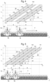
- the Figures 3-6 represent the load relations in a uniform representation.
- the spatial arrangement of the stabilization units 13 can be seen in the lower area.
- a time-distance diagram is arranged above each, which shows a path s traveled by the stabilization machine 1 over time t.
- Driving speed v is a direct correlation between the distance traveled s (location) of the respective stabilization unit 13 and the time t. Therefore the path s is plotted on the abscissa and the time t is plotted on the ordinate.
- ⁇ s ⁇ s / ⁇ t
- the formulated advantageous condition of different loads min, max at the same location applies in all operating modes.
- the longest interval i of the periodically changed load F at which this condition is fulfilled is the interval i which corresponds to the fundamental oscillation of the variable load F.
- the interval i is independent of the distance a between the stabilization units 13, the driving speed v and the operating mode (synchronous or asynchronous).
- the first harmonic is in Fig. 4 shown. It makes sense to choose a harmonic at low driving speed v and a large distance a between the stabilization units 13.
- a higher-frequency harmonic of the changing load F is advantageously selected ( Fig. 4 for synchronous operation).
- the 3rd harmonic i.e. the second harmonic
- n 3rd harmonic
- the Figures 7 and 8th represent the course of the load F over time.
- Fig. 8 For asynchronous operation shows Fig. 8 the course of the load F for one stabilization unit 13 with a solid line (load path 23) and for the other stabilization unit 13 with a dash-dotted line (load path 24).
- the fundamental oscillation n1 and the three first harmonics n2, n3, n4 are drawn one after the other in chronological order.
- Fig. 9 time the additional benefit of varying the surcharge F when applying work-integrated dynamic compaction control.
- the idea is shown as an example using the horizontal vibration amplitude y DGS of the stabilization unit 13. This changes depending on the load F.
- the horizontal vibration amplitude y DGS of the stabilization unit 13 represents all of the measurement and calculation variables described in the Austrian patent application A 331/2018 as well as additional measurements such as the vibrations in the environment (size and shape of wave propagation).
- the amplitude y DGS decreases in a first section 25.
- the amplitude y DGS increases again in a second section 26. Due to hysteresis, the two sections 25, 26 do not run on the same line. However, both sections 25, 26 have a recognizable kink 28 in a narrow load area 27, which represents an indication of a system change in the dynamic interaction system stabilization unit-track grate-track ballast.
- the position of this system change is an additional indicator of the ballast condition and correlates with the lateral displacement resistance of track 7. This indicator can also be used for automatic control of the process parameters.
Landscapes
- Engineering & Computer Science (AREA)
- Architecture (AREA)
- Civil Engineering (AREA)
- Structural Engineering (AREA)
- Machines For Laying And Maintaining Railways (AREA)
- Vibration Prevention Devices (AREA)
Claims (9)
- Machine de stabilisation d'une voie ferrée (7) avec lit de ballast (8), comprenant un châssis de machine (5) appuyé sur des mécanismes de roulement ferroviaires (6) et un module de stabilisation (13) pouvant se dérouler au moyen de rouleaux de module (14) sur des rails (10) de la voie ferrée (7) qui comprend un excitateur d'oscillations (15) pour la génération d'une force de frappe dynamique ainsi qu'un dispositif de sollicitation (19) pour la génération d'une charge (F) agissant sur la voie ferrée (7), caractérisée en ce que le dispositif de sollicitation (19) est accouplé à un dispositif de commande (20) pour la modification périodique de la charge (F) pendant un processus de stabilisation, lequel est configuré pour l'ajustement d'un intervalle (i) de la charge à modification périodique (F) avec une fréquence d'oscillation de l'excitateur d'oscillations (15).
- Machine selon la revendication 1, caractérisée en ce que des capteurs (21) pour la détection d'un tracé d'une force (F) agissant du module de stabilisation (13) sur la voie ferrée (7) sont disposés, que des signaux de mesure des capteurs (21) sont acheminés à un dispositif d'évaluation (22) et que le dispositif d'évaluation (22) est configuré pour la détermination d'une grandeur caractéristique dérivée du tracé de force.
- Machine selon la revendication 1 ou 2, caractérisée en ce qu'un circuit de régulation avec un régulateur, un dispositif de réglage pour le dispositif de sollicitation (19) et un dispositif de mesure pour la détection d'un paramètre de processus est configuré pour la régulation du paramètre de processus.
- Machine selon une des revendications 1 à 3, caractérisée en ce qu'un autre module de stabilisation (13) est disposé, avec un autre dispositif de sollicitation (19) qui est accouplé au dispositif de commande (20) pour la génération d'une charge à modification périodique (F).
- Procédé de réalisation d'un processus de stabilisation au moyen d'une machine selon une des revendications 1 à 4, dans lequel la voie ferrée (7) est mise en oscillation au moyen du module de stabilisation (13), caractérisé en ce qu'une charge à modification périodique (F) est exercée sur la voie ferrée (7) avec un intervalle (i) pendant le processus de stabilisation au moyen du dispositif de sollicitation (19) et qu'une fréquence d'oscillation ajustée avec l'intervalle (i) de la charge à modification périodique (F) est prédéfinie pour l'excitateur d'oscillations (15).
- Procédé selon la revendication 5, caractérisé en ce qu'un tracé d'une force agissant du module de stabilisation (13) sur la voie ferrée (7) est détecté au moyen de capteurs (21) et que des signaux de mesure des capteurs (21) sont évalués au moyen d'un dispositif d'évaluation (22) pour la détermination d'une grandeur caractéristique dérivée du tracé de force.
- Procédé selon la revendication 5 ou 6, caractérisé en ce que deux modules de stabilisation (13) disposés l'un derrière l'autre sont exploités ensemble avec chacun son propre dispositif de sollicitation (19).
- Procédé selon la revendication 7, caractérisé en ce que les deux dispositifs de sollicitation (19) sont exploités de manière synchrone ou asynchrone de sorte que les deux modules de stabilisation (13) exercent en fonctionnement synchrone la même charge (F) et en fonctionnement asynchrone différentes charges (F) sur la voie ferrée.
- Procédé selon la revendication 7 ou 8, caractérisé en ce qu'un intervalle (i) ajusté avec une vitesse de déplacement (v) de la machine est prédéfini pour la charge à modification périodique (F).
Applications Claiming Priority (2)
| Application Number | Priority Date | Filing Date | Title |
|---|---|---|---|
| ATA390/2019A AT523228B1 (de) | 2019-12-10 | 2019-12-10 | Maschine und Verfahren zum Stabilisieren eines Schottergleises |
| PCT/EP2020/081990 WO2021115722A1 (fr) | 2019-12-10 | 2020-11-13 | Machine et procédé de stabilisation d'une voie ferrée à ballast |
Publications (3)
| Publication Number | Publication Date |
|---|---|
| EP4073318A1 EP4073318A1 (fr) | 2022-10-19 |
| EP4073318C0 EP4073318C0 (fr) | 2024-01-10 |
| EP4073318B1 true EP4073318B1 (fr) | 2024-01-10 |
Family
ID=73455674
Family Applications (1)
| Application Number | Title | Priority Date | Filing Date |
|---|---|---|---|
| EP20808036.6A Active EP4073318B1 (fr) | 2019-12-10 | 2020-11-13 | Machine et procédé de stabilisation d'une voie ferrée à ballast |
Country Status (6)
| Country | Link |
|---|---|
| US (1) | US12559889B2 (fr) |
| EP (1) | EP4073318B1 (fr) |
| JP (1) | JP7665625B2 (fr) |
| AT (1) | AT523228B1 (fr) |
| ES (1) | ES2977280T3 (fr) |
| WO (1) | WO2021115722A1 (fr) |
Families Citing this family (2)
| Publication number | Priority date | Publication date | Assignee | Title |
|---|---|---|---|---|
| AT523034A3 (de) * | 2019-09-18 | 2024-02-15 | Plasser & Theurer Export Von Bahnbaumaschinen Gmbh | Maschine und Verfahren zum Stabilisieren eines Gleises |
| AT18149U1 (de) * | 2022-09-06 | 2024-03-15 | Plasser & Theurer Export Von Bahnbaumaschinen Gmbh | Verfahren und Vorrichtung zum Bestimmen der Beschaffenheit, insbesondere des Verdichtungsgrads, eines Gleisbetts |
Family Cites Families (14)
| Publication number | Priority date | Publication date | Assignee | Title |
|---|---|---|---|---|
| AT343165B (de) * | 1975-01-31 | 1978-05-10 | Plasser Bahnbaumasch Franz | Fahrbare schotterbett-verdichtmaschine zur korrektur der gleislage |
| AT370154B (de) * | 1981-03-09 | 1983-03-10 | Plasser Bahnbaumasch Franz | Gleisstopfmaschine mit voll a-synchronem stopfaggregat |
| AT401398B (de) * | 1990-02-06 | 1996-08-26 | Plasser Bahnbaumasch Franz | Kontinuierlich verfahrbare gleisbaumaschine zum verdichten der schotterbettung |
| AT400162B (de) * | 1990-02-06 | 1995-10-25 | Plasser Bahnbaumasch Franz | Verfahren und gleisbaumaschine zur messung des querverschiebewiderstandes |
| GB2250765B (en) * | 1990-02-06 | 1994-04-20 | Plasser Bahnbaumasch Franz | Process for consolidating railway track ballast |
| EP0726360B1 (fr) * | 1995-02-09 | 1999-02-24 | Franz Plasser Bahnbaumaschinen-Industriegesellschaft m.b.H. | Procédé et machine pour le bourrage et l'assainissement d'une voie ferrée |
| DK0952254T3 (da) * | 1998-03-27 | 2004-03-15 | Plasser Bahnbaumasch Franz | Fremgangsmåde til sporpositionskorrektion |
| PL1817463T3 (pl) | 2004-11-22 | 2009-01-30 | Franz Plasser Bahnbaumaschinen Ind Mbh | Sposób korekcji wysokościowych błędów położenia toru |
| NO2902546T3 (fr) * | 2014-01-30 | 2018-03-24 | ||
| AT518373B1 (de) * | 2016-02-24 | 2018-05-15 | Plasser & Theurer Export Von Bahnbaumaschinen Gmbh | Maschine mit Stabilisierungsaggregat und Messverfahren |
| AT518693B1 (de) * | 2016-05-24 | 2020-02-15 | Plasser & Theurer Exp Von Bahnbaumaschinen G M B H | Prüfvorrichtung und Verfahren zum Prüfen eines Stopfaggregates |
| AT520056B1 (de) * | 2017-05-29 | 2020-12-15 | Plasser & Theurer Export Von Bahnbaumaschinen Gmbh | Verfahren und Vorrichtung zum Verdichten eines Gleisschotterbetts |
| AT520791B1 (de) * | 2017-12-21 | 2020-08-15 | Plasser & Theurer Export Von Bahnbaumaschinen Gmbh | Verfahren zum Betreiben eines Stopfaggregats einer Gleisbaumaschine sowie Stopfvorrichtung zur Gleisbettverdichtung und Gleisbaumaschine |
| AT16604U1 (de) | 2018-02-13 | 2020-02-15 | Plasser & Theurer Export Von Bahnbaumaschinen Gmbh | Maschine zum Stabilisieren eines Gleises |
-
2019
- 2019-12-10 AT ATA390/2019A patent/AT523228B1/de active
-
2020
- 2020-11-13 EP EP20808036.6A patent/EP4073318B1/fr active Active
- 2020-11-13 US US17/779,346 patent/US12559889B2/en active Active
- 2020-11-13 ES ES20808036T patent/ES2977280T3/es active Active
- 2020-11-13 JP JP2022535418A patent/JP7665625B2/ja active Active
- 2020-11-13 WO PCT/EP2020/081990 patent/WO2021115722A1/fr not_active Ceased
Also Published As
| Publication number | Publication date |
|---|---|
| EP4073318C0 (fr) | 2024-01-10 |
| JP7665625B2 (ja) | 2025-04-21 |
| EP4073318A1 (fr) | 2022-10-19 |
| ES2977280T3 (es) | 2024-08-21 |
| JP2023505854A (ja) | 2023-02-13 |
| AT523228A1 (de) | 2021-06-15 |
| US20220403605A1 (en) | 2022-12-22 |
| US12559889B2 (en) | 2026-02-24 |
| WO2021115722A1 (fr) | 2021-06-17 |
| AT523228B1 (de) | 2024-06-15 |
Similar Documents
| Publication | Publication Date | Title |
|---|---|---|
| EP3870760B1 (fr) | Procédé et machine pour stabiliser une voie ferrée | |
| EP2902546B2 (fr) | Dispositif de compression du lit de ballast d'une voie ferrée | |
| DE69423048T2 (de) | Regelung für eine verfestigungsmaschine mit messeinrichtung für die eigenschaften des grundmaterials | |
| EP1516961B1 (fr) | Méthode de détermination de la rigidité du sol et dispositif de compactage de sol | |
| EP0688902B1 (fr) | Méthode de mesure de la résistance aux déplacements latéraux des rails d'une voie ferrée | |
| EP2701845B1 (fr) | Procédé de réglage de pression dans une fente d'une presse à rouleaux | |
| EP2627826B1 (fr) | Méthode pour la détermination de la rigidité et/ou de l'amortissement d'un domaine d'une solidité | |
| DE4102869A1 (de) | Gleisbaumaschine zum verdichten der schotterbettung | |
| DE4102872C2 (de) | Kontinuierlich verfahrbare Gleisbaumaschine zum Verdichten der Schotterbettung und Verfahren zur kontinuierlichen Absenkung des Gleises | |
| AT524861B1 (de) | Verfahren und Maschine zum Stopfen eines Gleises | |
| AT523228B1 (de) | Maschine und Verfahren zum Stabilisieren eines Schottergleises | |
| EP4134485B1 (fr) | Procédé de stabilisation du lit de ballast d'une voie | |
| DE102020110468B4 (de) | Verfahren zur Regelung der Dämpfung der Bewegung einer Presswalze einer Hochdruckwalzenpresse und korrespondierende Hochdruckwalzenpresse | |
| EP2286025B1 (fr) | Mécanisme d'agitation | |
| EP4179146B1 (fr) | Machine et procédé pour compacter un lit de ballast d'une voie | |
| AT524860B1 (de) | Vorrichtung und Verfahren zum Verdichten eines Gleisbettes | |
| AT506025A2 (de) | Verfahren und vorrichtung zur dämpfung von walzenschwingungen | |
| AT503437B1 (de) | Verfahren zum unterstopfen und stabilisieren eines gleises | |
| WO2024052306A1 (fr) | Procédé et dispositif de détermination de la qualité, en particulier du degré de compactage, d'un lit de voie |
Legal Events
| Date | Code | Title | Description |
|---|---|---|---|
| STAA | Information on the status of an ep patent application or granted ep patent |
Free format text: STATUS: UNKNOWN |
|
| STAA | Information on the status of an ep patent application or granted ep patent |
Free format text: STATUS: THE INTERNATIONAL PUBLICATION HAS BEEN MADE |
|
| PUAI | Public reference made under article 153(3) epc to a published international application that has entered the european phase |
Free format text: ORIGINAL CODE: 0009012 |
|
| STAA | Information on the status of an ep patent application or granted ep patent |
Free format text: STATUS: REQUEST FOR EXAMINATION WAS MADE |
|
| 17P | Request for examination filed |
Effective date: 20220711 |
|
| AK | Designated contracting states |
Kind code of ref document: A1 Designated state(s): AL AT BE BG CH CY CZ DE DK EE ES FI FR GB GR HR HU IE IS IT LI LT LU LV MC MK MT NL NO PL PT RO RS SE SI SK SM TR |
|
| DAV | Request for validation of the european patent (deleted) | ||
| DAX | Request for extension of the european patent (deleted) | ||
| GRAP | Despatch of communication of intention to grant a patent |
Free format text: ORIGINAL CODE: EPIDOSNIGR1 |
|
| STAA | Information on the status of an ep patent application or granted ep patent |
Free format text: STATUS: GRANT OF PATENT IS INTENDED |
|
| RIC1 | Information provided on ipc code assigned before grant |
Ipc: E01B 27/16 20060101ALI20230524BHEP Ipc: E01B 27/20 20060101AFI20230524BHEP |
|
| INTG | Intention to grant announced |
Effective date: 20230628 |
|
| GRAS | Grant fee paid |
Free format text: ORIGINAL CODE: EPIDOSNIGR3 |
|
| GRAA | (expected) grant |
Free format text: ORIGINAL CODE: 0009210 |
|
| STAA | Information on the status of an ep patent application or granted ep patent |
Free format text: STATUS: THE PATENT HAS BEEN GRANTED |
|
| AK | Designated contracting states |
Kind code of ref document: B1 Designated state(s): AL AT BE BG CH CY CZ DE DK EE ES FI FR GB GR HR HU IE IS IT LI LT LU LV MC MK MT NL NO PL PT RO RS SE SI SK SM TR |
|
| REG | Reference to a national code |
Ref country code: GB Ref legal event code: FG4D Free format text: NOT ENGLISH |
|
| REG | Reference to a national code |
Ref country code: CH Ref legal event code: EP |
|
| REG | Reference to a national code |
Ref country code: DE Ref legal event code: R096 Ref document number: 502020006715 Country of ref document: DE |
|
| REG | Reference to a national code |
Ref country code: IE Ref legal event code: FG4D Free format text: LANGUAGE OF EP DOCUMENT: GERMAN |
|
| U01 | Request for unitary effect filed |
Effective date: 20240111 |
|
| U07 | Unitary effect registered |
Designated state(s): AT BE BG DE DK EE FI FR IT LT LU LV MT NL PT SE SI Effective date: 20240119 |
|
| PG25 | Lapsed in a contracting state [announced via postgrant information from national office to epo] |
Ref country code: IS Free format text: LAPSE BECAUSE OF FAILURE TO SUBMIT A TRANSLATION OF THE DESCRIPTION OR TO PAY THE FEE WITHIN THE PRESCRIBED TIME-LIMIT Effective date: 20240510 |
|
| PG25 | Lapsed in a contracting state [announced via postgrant information from national office to epo] |
Ref country code: GR Free format text: LAPSE BECAUSE OF FAILURE TO SUBMIT A TRANSLATION OF THE DESCRIPTION OR TO PAY THE FEE WITHIN THE PRESCRIBED TIME-LIMIT Effective date: 20240411 |
|
| PG25 | Lapsed in a contracting state [announced via postgrant information from national office to epo] |
Ref country code: HR Free format text: LAPSE BECAUSE OF FAILURE TO SUBMIT A TRANSLATION OF THE DESCRIPTION OR TO PAY THE FEE WITHIN THE PRESCRIBED TIME-LIMIT Effective date: 20240110 Ref country code: RS Free format text: LAPSE BECAUSE OF FAILURE TO SUBMIT A TRANSLATION OF THE DESCRIPTION OR TO PAY THE FEE WITHIN THE PRESCRIBED TIME-LIMIT Effective date: 20240410 |
|
| PG25 | Lapsed in a contracting state [announced via postgrant information from national office to epo] |
Ref country code: RS Free format text: LAPSE BECAUSE OF FAILURE TO SUBMIT A TRANSLATION OF THE DESCRIPTION OR TO PAY THE FEE WITHIN THE PRESCRIBED TIME-LIMIT Effective date: 20240410 Ref country code: NO Free format text: LAPSE BECAUSE OF FAILURE TO SUBMIT A TRANSLATION OF THE DESCRIPTION OR TO PAY THE FEE WITHIN THE PRESCRIBED TIME-LIMIT Effective date: 20240410 Ref country code: IS Free format text: LAPSE BECAUSE OF FAILURE TO SUBMIT A TRANSLATION OF THE DESCRIPTION OR TO PAY THE FEE WITHIN THE PRESCRIBED TIME-LIMIT Effective date: 20240510 Ref country code: HR Free format text: LAPSE BECAUSE OF FAILURE TO SUBMIT A TRANSLATION OF THE DESCRIPTION OR TO PAY THE FEE WITHIN THE PRESCRIBED TIME-LIMIT Effective date: 20240110 Ref country code: GR Free format text: LAPSE BECAUSE OF FAILURE TO SUBMIT A TRANSLATION OF THE DESCRIPTION OR TO PAY THE FEE WITHIN THE PRESCRIBED TIME-LIMIT Effective date: 20240411 |
|
| PG25 | Lapsed in a contracting state [announced via postgrant information from national office to epo] |
Ref country code: PL Free format text: LAPSE BECAUSE OF FAILURE TO SUBMIT A TRANSLATION OF THE DESCRIPTION OR TO PAY THE FEE WITHIN THE PRESCRIBED TIME-LIMIT Effective date: 20240110 |
|
| REG | Reference to a national code |
Ref country code: ES Ref legal event code: FG2A Ref document number: 2977280 Country of ref document: ES Kind code of ref document: T3 Effective date: 20240821 |
|
| PG25 | Lapsed in a contracting state [announced via postgrant information from national office to epo] |
Ref country code: PL Free format text: LAPSE BECAUSE OF FAILURE TO SUBMIT A TRANSLATION OF THE DESCRIPTION OR TO PAY THE FEE WITHIN THE PRESCRIBED TIME-LIMIT Effective date: 20240110 |
|
| REG | Reference to a national code |
Ref country code: DE Ref legal event code: R097 Ref document number: 502020006715 Country of ref document: DE |
|
| PG25 | Lapsed in a contracting state [announced via postgrant information from national office to epo] |
Ref country code: SM Free format text: LAPSE BECAUSE OF FAILURE TO SUBMIT A TRANSLATION OF THE DESCRIPTION OR TO PAY THE FEE WITHIN THE PRESCRIBED TIME-LIMIT Effective date: 20240110 |
|
| PG25 | Lapsed in a contracting state [announced via postgrant information from national office to epo] |
Ref country code: CZ Free format text: LAPSE BECAUSE OF FAILURE TO SUBMIT A TRANSLATION OF THE DESCRIPTION OR TO PAY THE FEE WITHIN THE PRESCRIBED TIME-LIMIT Effective date: 20240110 |
|
| PG25 | Lapsed in a contracting state [announced via postgrant information from national office to epo] |
Ref country code: SK Free format text: LAPSE BECAUSE OF FAILURE TO SUBMIT A TRANSLATION OF THE DESCRIPTION OR TO PAY THE FEE WITHIN THE PRESCRIBED TIME-LIMIT Effective date: 20240110 |
|
| PG25 | Lapsed in a contracting state [announced via postgrant information from national office to epo] |
Ref country code: SM Free format text: LAPSE BECAUSE OF FAILURE TO SUBMIT A TRANSLATION OF THE DESCRIPTION OR TO PAY THE FEE WITHIN THE PRESCRIBED TIME-LIMIT Effective date: 20240110 Ref country code: SK Free format text: LAPSE BECAUSE OF FAILURE TO SUBMIT A TRANSLATION OF THE DESCRIPTION OR TO PAY THE FEE WITHIN THE PRESCRIBED TIME-LIMIT Effective date: 20240110 Ref country code: RO Free format text: LAPSE BECAUSE OF FAILURE TO SUBMIT A TRANSLATION OF THE DESCRIPTION OR TO PAY THE FEE WITHIN THE PRESCRIBED TIME-LIMIT Effective date: 20240110 Ref country code: CZ Free format text: LAPSE BECAUSE OF FAILURE TO SUBMIT A TRANSLATION OF THE DESCRIPTION OR TO PAY THE FEE WITHIN THE PRESCRIBED TIME-LIMIT Effective date: 20240110 |
|
| PLBE | No opposition filed within time limit |
Free format text: ORIGINAL CODE: 0009261 |
|
| STAA | Information on the status of an ep patent application or granted ep patent |
Free format text: STATUS: NO OPPOSITION FILED WITHIN TIME LIMIT |
|
| 26N | No opposition filed |
Effective date: 20241011 |
|
| U20 | Renewal fee for the european patent with unitary effect paid |
Year of fee payment: 5 Effective date: 20241202 |
|
| PG25 | Lapsed in a contracting state [announced via postgrant information from national office to epo] |
Ref country code: MC Free format text: LAPSE BECAUSE OF FAILURE TO SUBMIT A TRANSLATION OF THE DESCRIPTION OR TO PAY THE FEE WITHIN THE PRESCRIBED TIME-LIMIT Effective date: 20240110 |
|
| PG25 | Lapsed in a contracting state [announced via postgrant information from national office to epo] |
Ref country code: IE Free format text: LAPSE BECAUSE OF NON-PAYMENT OF DUE FEES Effective date: 20241113 |
|
| REG | Reference to a national code |
Ref country code: CH Ref legal event code: U11 Free format text: ST27 STATUS EVENT CODE: U-0-0-U10-U11 (AS PROVIDED BY THE NATIONAL OFFICE) Effective date: 20251201 |
|
| U20 | Renewal fee for the european patent with unitary effect paid |
Year of fee payment: 6 Effective date: 20251201 |
|
| PGFP | Annual fee paid to national office [announced via postgrant information from national office to epo] |
Ref country code: GB Payment date: 20251022 Year of fee payment: 6 |
|
| PGFP | Annual fee paid to national office [announced via postgrant information from national office to epo] |
Ref country code: CH Payment date: 20251201 Year of fee payment: 6 |
|
| PGFP | Annual fee paid to national office [announced via postgrant information from national office to epo] |
Ref country code: ES Payment date: 20251202 Year of fee payment: 6 |
|
| PG25 | Lapsed in a contracting state [announced via postgrant information from national office to epo] |
Ref country code: HU Free format text: LAPSE BECAUSE OF FAILURE TO SUBMIT A TRANSLATION OF THE DESCRIPTION OR TO PAY THE FEE WITHIN THE PRESCRIBED TIME-LIMIT; INVALID AB INITIO Effective date: 20201113 |
|
| PG25 | Lapsed in a contracting state [announced via postgrant information from national office to epo] |
Ref country code: CY Free format text: LAPSE BECAUSE OF FAILURE TO SUBMIT A TRANSLATION OF THE DESCRIPTION OR TO PAY THE FEE WITHIN THE PRESCRIBED TIME-LIMIT; INVALID AB INITIO Effective date: 20201113 |