EP4073894B1 - Dispositif de guidage de ligne pour des applications de salle blanche, ainsi que chaîne de support et maillon de chaîne pour celui-ci - Google Patents
Dispositif de guidage de ligne pour des applications de salle blanche, ainsi que chaîne de support et maillon de chaîne pour celui-ci Download PDFInfo
- Publication number
- EP4073894B1 EP4073894B1 EP20838372.9A EP20838372A EP4073894B1 EP 4073894 B1 EP4073894 B1 EP 4073894B1 EP 20838372 A EP20838372 A EP 20838372A EP 4073894 B1 EP4073894 B1 EP 4073894B1
- Authority
- EP
- European Patent Office
- Prior art keywords
- chain
- longitudinal portion
- cross
- longitudinal direction
- chain link
- Prior art date
- Legal status (The legal status is an assumption and is not a legal conclusion. Google has not performed a legal analysis and makes no representation as to the accuracy of the status listed.)
- Active
Links
Images


Classifications
-
- H—ELECTRICITY
- H02—GENERATION; CONVERSION OR DISTRIBUTION OF ELECTRIC POWER
- H02G—INSTALLATION OF ELECTRIC CABLES OR LINES, OR OF COMBINED OPTICAL AND ELECTRIC CABLES OR LINES
- H02G11/00—Arrangements of electric cables or lines between relatively-movable parts
- H02G11/006—Arrangements of electric cables or lines between relatively-movable parts using extensible carrier for the cable, e.g. self-coiling spring
-
- F—MECHANICAL ENGINEERING; LIGHTING; HEATING; WEAPONS; BLASTING
- F16—ENGINEERING ELEMENTS AND UNITS; GENERAL MEASURES FOR PRODUCING AND MAINTAINING EFFECTIVE FUNCTIONING OF MACHINES OR INSTALLATIONS; THERMAL INSULATION IN GENERAL
- F16G—BELTS, CABLES, OR ROPES, PREDOMINANTLY USED FOR DRIVING PURPOSES; CHAINS; FITTINGS PREDOMINANTLY USED THEREFOR
- F16G13/00—Chains
- F16G13/12—Hauling- or hoisting-chains so called ornamental chains
- F16G13/16—Hauling- or hoisting-chains so called ornamental chains with arrangements for holding electric cables, hoses, or the like
-
- H—ELECTRICITY
- H02—GENERATION; CONVERSION OR DISTRIBUTION OF ELECTRIC POWER
- H02G—INSTALLATION OF ELECTRIC CABLES OR LINES, OR OF COMBINED OPTICAL AND ELECTRIC CABLES OR LINES
- H02G3/00—Installations of electric cables or lines or protective tubing therefor in or on buildings, equivalent structures or vehicles
- H02G3/02—Details
- H02G3/04—Protective tubing or conduits, e.g. cable ladders or cable troughs
- H02G3/0462—Tubings, i.e. having a closed section
- H02G3/0487—Tubings, i.e. having a closed section with a non-circular cross-section
Definitions
- the invention lies in the field of line routing devices, in particular for clean room applications, for the protected dynamic routing of supply lines such as cables, hoses or the like between two connection points, at least one of which is movable relative to the other.
- Such dynamic or active cable routing devices protect the cables against unwanted stresses when moving, usually between a stationary connection and a moving consumer, for example on a machine. They are typically linear or can be moved back and forth in a plane of movement along a longitudinal direction and typically form two essentially elongated strands and an approximately U-shaped deflection arc in between.
- the invention relates to support chains for supporting a cable routing device according to claims 1, 9 and 13.
- the invention is specifically aimed at a line routing device intended for clean room applications with a flexible covering, which has a number of receiving channels arranged next to one another and extending in the longitudinal direction for dust-protecting covering of supply lines, in which at least one supply line is typically accommodated.
- the covering is intended in particular to prevent abrasion of the cables, which inevitably occurs due to driving movement, from being released into the environment.
- a covering made of suitable material can improve overall abrasion behavior.
- support chains are used to support the cable routing, especially in the extended position of a self-supporting or non-supporting strand.
- the support chain can be arranged in a receiving channel instead of a line and can assume stretched positions to form the strands and an arcuate position to form a deflection arc, with the support chain also specifying the desired radius.
- transport chains which can be designed as roller or bushing chains and are only subjected to tension.
- DE1281350B describes, for example, a transport chain made of chain links that are connected to one another in a freely pivotable manner by circular cylindrical joint pins. Additional U-shaped “transport links” are placed on the hinge pins as a cover from above. The “transport links” have a transport plate on the top and thereby form a closed surface on the top in the extended position for supporting goods to be transported. The end faces of the transport plates act as stretch stop surfaces.
- Another example of a non-generic chain for transmitting traction is in DE2141709A1 shown.
- This bush chain is made up of side parts that are connected longitudinally and transversely by hinge pins. In order to reduce the load on the hinge pins, the side parts adjacent to one another in the longitudinal direction hook into one another in the extended position in order to absorb part of the tensile force.
- the chains off DE1281350B or. DE2141709A1 However, they cannot specify the desired radius in the angled state because they do not have any stop surfaces in the curved position because they are not intended for guiding cable protection.
- a cable routing device with generic support chains was, for example, in DE 10 2010 053 317 A1 and in DE 10 2011 015 119 A1 suggested.
- a generic support chain of this type has a large number of individual chain links which are connected to one another in an articulated manner, each with a first longitudinal section and a second longitudinal section complementary thereto in the longitudinal direction of the chain or of the individual link.
- the second longitudinal section can - similar to a forked tab - be bifurcated or forked-like, with two side parts and a free space between them, into which the first longitudinal section of the following chain link is inserted and held at least against lateral transverse movement.
- Both longitudinal sections are designed in a suitable manner in order to connect the chain links to one another in a predetermined manner, in particular in such a way that a predetermined geometry of the deflection bend is maintained.
- the deflection arc is typically bent approximately U-shaped about a deflection axis running transversely to the longitudinal direction, ie with a deflection axis parallel to the width direction.
- Such support chains ensure in particular that a certain radius is maintained in the deflection bend, i.e. the cables are protected against kinking.
- the usable length is increased because the support chains enable larger unsupported lengths, usually of the upper run. So that such a support chain can be used instead of a cable in the casing, it typically has very compact dimensions, at least in cross section, especially in comparison to common energy chains.
- a generic support chain itself does not have a receiving channel for cables.
- Multi-layer structures are also known, as in DE 10 2012 100 359 A1 proposed, in which more than two support chains are used in the covering of a supporting layer, up to layers without any cable, ie with only support chains in the covering of a layer.
- a core aim of the present invention is therefore to optimize the design of the support chain compared to the prior art, in particular to the extent that a longer service life of the support chain can be achieved.
- the design of the support chain which is particularly compact in cross section as intended, should not be enlarged or at most insignificantly.
- inside means radially inside or facing the deflection axis and outside means radially outside or facing away from the deflection axis.
- front and “rear” refer to two longitudinal ends of the individual chain link and serve only as an abbreviation, without any statement about function and structure, since the support chain can always be moved back and forth in two directions.
- the front first longitudinal section has a projection in one end region on the inside and transversely to the longitudinal direction and that the rear second longitudinal section on its inner side with respect to the deflection bend (in short: inside ) one the side parts connecting, inside cross bridge with a stretch stop surface for the stretched position and a recess adjacent to it in the longitudinal direction at the front.
- a more favorable introduction of force is created thanks to the projection that engages the other chain link on the front side of the cross bridge (similar to a rear grip) in that part of the surface pressure that would otherwise arise on the stretch stop surface is diverted into a tensile force with which the projection is moved in the longitudinal direction acts on the cross bridge.
- a compact overall height compared to the overall length, especially of the cross bridge larger self-supporting lengths can be achieved.
- this also means that with the same unsupported length of the maximum extended strand, a longer overall service life of the support chain can be achieved.
- This effect is particularly advantageous for chain links that are made of a material that is slightly deformable under nominal loads, in particular plastic.
- the articulated connections can be the weak point of the support chain, which is the first to fail. In synergy with the first-mentioned effect, the service life can be further increased.
- the interaction of the projection and cross bridge with their associated recess also allows a more favorable leverage effect in the power transmission. Due to the more favorable application of force in the extended position, a noticeable increase in the self-supporting length or service life of the support chain can be achieved and/or the load-bearing capacity can be increased, with a consistently compact design, ie with a cross section smaller than or equal to that of a receiving channel of a conventional casing, so that for a specific application Overall, fewer support chains are required.
- the first longitudinal section can hook with its projection onto the corresponding second longitudinal section of the next chain link, in particular in the manner of a hook or a pawl or the like.
- the projection can hook into the recess of the second longitudinal section or reach behind the cross bridge.
- the gripping behind during the transition from the bent to the extended position should be as low-wear as possible, i.e. without undesirable abrasion. Locking the projection on the other chain link is usually not necessary or rather undesirable.
- the chain links are connected to form a strand and should have the proposed design at least over the desired longitudinal section that is to be self-supporting.
- the support chain preferably consists exclusively of such or identical chain links.
- the second longitudinal section has a transverse stop on the outer side of the deflection bend, i.e. its outside and in its rear end region, which lies opposite the outside of the first longitudinal section of an adjacent chain link as an abutment for the extended position.
- abutment allows one longitudinal section to “tilt” in the other.
- the outer cross stop at the rear area can in particular be designed as an outside cross bridge connecting the side parts. This provides a robust abutment and the chain link becomes more stable or stiffer overall.
- the chain links preferably have a design with a front or first and a rear or second longitudinal section which are designed to be complementary to one another, so that the front longitudinal section of a chain link can be connected to the rear longitudinal section of the next chain link, in particular can be connected in an articulated manner. At least a part of the front longitudinal section of a chain link is movably mounted in the free space of the rear longitudinal section of the next chain link.
- an articulated connection is generally to be understood as a connection which enables the relative pivoting of two chain links to one another.
- a single-value, loose joint connection (floating bearing) is within the scope of the invention.
- the projection can form a contact surface which serves to contact a frontal front region of the inside cross bridge and is arranged essentially perpendicular to the longitudinal direction of the support chain or the individual chain link.
- the introduction of force can be carried out particularly cheaply, in particular with little wear and low abrasion, via a contact surface that is aligned perpendicular to the longitudinal direction, ie also to the direction of the tensile force.
- a contact surface perpendicular to the longitudinal direction With a contact surface perpendicular to the longitudinal direction, a noticeable proportion of the forces arising from weight in the extended position can be introduced as a tensile force onto the cross bridge, so that a more favorable load on the component is created.
- the cross bridge has a flat dimension, with a dimension in the longitudinal direction significantly larger than the overall height in the cross section perpendicular to the longitudinal direction, ie in connection with compact chain links.
- the force-transmitting surfaces of the projection and cross bridge at least slightly obliquely or rounded with respect to the longitudinal and height direction of the chain links, for example to optimize abrasion edges.
- the first longitudinal section is essentially nose-shaped and has a front end that is cranked or projects towards the inside (towards the axis of the deflection bend).
- the projection according to the first aspect can be formed at this end.
- the first longitudinal section continues to form a recess on its inside, for example in the central region, into which the inside cross bridge of the adjacent chain link can partially immerse or be completely accommodated in the extended position. This enables a relatively slim design, especially with a low overall height of the chain links.
- the first and second longitudinal sections typically have stretch stop surfaces, i.e. surfaces that work together in pairs when the chain links are in the stretched position and lie essentially parallel to the longitudinal direction.
- the projection and the inside cross bridge have interacting contact surfaces which are essentially perpendicular to the stretch stop surfaces.
- the contact surfaces can be arranged in such a way that the projection of a chain link, in the extended position, rests or engages with its contact surface as flatly as possible on the contact surface of the inside cross bridge of the following chain link in a force-transmitting manner. This also creates favorable conditions for force transmission or introduction of force with a force component in the longitudinal direction of the chain.
- the projection and in particular its contact surface extends over the entire width of the first longitudinal section (viewed in cross section perpendicular to the longitudinal direction). Furthermore, in an advantageous dimensioning, the projection and in particular its contact surface can be projected inwardly (towards the deflection axis) with a projection of at least 5%, preferably at least 10%, of the total height of the chain link. protrude (viewed in cross section perpendicular to the longitudinal direction). Comparatively large contact surfaces reduce the surface pressure between the abutting chain links.
- the projection can be arranged in the front end quarter of the first longitudinal section.
- a leverage effect (with regard to the joint axis), especially in conjunction with an abutment, can be further increased and particularly favorable force ratios in extension can be achieved.
- the inside cross bridge is preferably arranged in the opposite or facing away rear half of the second longitudinal section. The recess lies in the longitudinal direction between the cross bridge and the end projection, i.e. closer to the central region of the chain link.
- the recess can form an opening on the front side of the transverse bridge to the inside of the chain link, which opens outwards in particular from the free space between the side areas.
- the recess essentially completely accommodates the projection in the extended position.
- the recess for stabilization in the transverse direction or for stabilization in the lateral direction, it is also advantageous to receive the projection in the recess in a positive manner.
- the construction of the chain links is optimized in terms of force transmission and service life, but in particular with regard to the stops in the arcuate position of the deflection bend.
- the chain links are plugged together from the outside to the inside in the direction transverse to the longitudinal direction, relative to the deflection bend. Due to the design, these fork-like chain links therefore enable the tab-like side areas to be stabilized only on one side, either radially inside or radially outside in relation to the deflection bend.
- each chain link in its second longitudinal section on its outside has an outside cross connection in addition to one on the inside provided internal cross connection.
- the cross connections can in particular be designed as a transverse web and/or cross bridge and are both preferably plate-like or have a significantly lower overall height compared to the overall length in the longitudinal direction.
- the cross connections bridge the free space between the side areas and connect them in a stabilizing manner.
- This design enables the inside transverse bridge in the stretched position to interact with an inside stretch stop surface of the first longitudinal section and also enables the outside crossbar to interact with an outside arch stop surface of the first longitudinal section, namely in the arcuate or deflected position in the deflection bend.
- the webs or bridges on both sides can therefore also improve the power transmission between chain links or the introduction of force in the arcuate position (in the deflection arch), regardless of whether a projection according to the first aspect is used.
- stretch stop surface or curved stop surface refer to stop surfaces according to their primary function (i.e. not according to their shape), namely as effective in the stretched position or in the deflection curve.
- abrasion or wear can be reduced compared to known designs of the sheet stop, i.e. with comparatively narrow stops on the end faces.
- a cross bridge can be limited in the longitudinal direction on both sides or at the front and back by recesses or openings.
- a transverse web on the other hand, can preferably merge into the trunk or body of the chain link on one side, in particular on the front side or towards the first longitudinal section, or be formed on it.
- the trunk or body of the chain link can be designed, for example, as a solid body or monolithic, and is preferably inherently more stable than the side areas.
- a crossbar is preferably provided on the outside and a crossbridge on the inside. This design can be combined particularly advantageously with the first aspect.
- the transverse web is preferably arranged in a front part of the second longitudinal section, i.e. on the side towards the first longitudinal section.
- an external crossbar according to the second aspect is not structurally possible.
- first longitudinal section can be inserted into the second longitudinal section of a chain link to be connected in the longitudinal direction, in particular in the “front” direction, for the purpose of connecting the chain links, for example also for an articulated connection between two chain links.
- each chain link can also have an outside cross bridge in its second longitudinal section on the outside in addition to the crossbar in a front area.
- Such an additional cross bridge is preferably arranged in a rear area.
- the chain link can also each comprise a first and a second outside cross bridge, in particular instead of a cross bar on the outside.
- the additional cross bridge also has a reinforcing effect and is preferably provided in the rear end region of the second longitudinal section.
- a corresponding cross bridge on the outside at the rear end region of the second longitudinal section is also particularly advantageous in connection with the first aspect, namely can be used as an abutment for introducing force via the projection (see above).
- the first longitudinal section can have a protruding area on the outside, which in the arcuate position (in the deflection bend) extends or engages on the outside between the crossbar and the crossbridge or both outside crossbridges.
- This design makes it possible, for example, for the first longitudinal section to be connected to the second longitudinal section arcuate position tilted and in particular jammed with an edge of the protruding area. This can be achieved in particular by attacking the further or rear outside cross bridge. In this way, when loading in the pulling direction (one direction of travel) in an arcuate position, unintentional loosening of the chain links, especially with comparatively high pulling forces, can be avoided.
- the complementary longitudinal sections of successive chain links can form a locking connection that reliably avoids loosening in the longitudinal direction under the intended tensile forces.
- each chain link can have two opposite pins or locking pins in one of the two longitudinal sections, which protrude laterally to the longitudinal direction, with corresponding recesses being provided on the corresponding longitudinal section, with which the side pins can be locked.
- the pins are advantageously provided on the first longitudinal section, so that they can engage in recesses on the side parts of the second longitudinal section without protruding laterally over the side parts.
- the locking pins have insertion bevels that taper obliquely in the longitudinal direction, in particular tapering in the longitudinal direction from back to front (or in the insertion direction).
- Appropriate insertion bevels simplify assembling the chain by simply plugging the chain links together in the longitudinal direction of the chain.
- the recesses which are provided for locking with the aforementioned locking pins are assigned insertion grooves which open into the recesses. Thanks to such insertion grooves, the pins can be inserted into the recesses more easily. For plugging the chain links together in the longitudinal direction, it is advantageous if the insertion grooves extend essentially in the longitudinal direction.
- two side regions of the wider or rear longitudinal section each have a front end face and a rear end face, which lie opposite one another in adjacent chain links.
- the front end face forms a joint area and the rear end face forms a complementary joint area, with the joint areas depending on the load case, in particular at least under shear load (in a direction of movement, here "forwards”. ”) work together to create a desired joint connection between both chain links.
- the respective joint areas of the front end face of a chain link and the rear end face of an adjacent or next chain link work together.
- this design ensures that the front end face of one chain link can rest on the rear end face of the adjacent other chain link for the transmission of thrust force.
- the front areas of the side parts themselves can be used as joint areas for the articulated connection of two chain links, so that the usual and wear-prone joint connection with a joint pin/receptacle can be omitted.
- the end faces offer a comparatively large surface area for design, so that the surface pressure when shear force is introduced can be reduced or the long-term durability of the joint can be increased.
- the joint areas can be designed in the manner of a floating bearing or a single-value bearing, which only forms a defined bearing or transmits force in the direction of the shear load, in particular only defining a pivot axis or rotation axis for pivoting both chain links when the support chain is under shear load.
- the joint areas can form a sliding pairing, in particular a single-value tilting bearing, whereby, for example, the joint areas of the front end faces of one chain link can be designed as a convex pressure piece, e.g. with surfaces in the form of cylinder sections, and the rear end faces of the other chain link can be designed as a cooperating concave tilting support with a complementary surface .
- the joint areas transmit essentially no tensile forces during operation of the support chain.
- An articulated connection in the form of a floating bearing is inherently more durable and can be combined particularly advantageously with the first aspect. It allows a relative displacement in the height direction or a displacement of the pivot point, especially under weight load in the extended position, in order to optimize the more favorable introduction of force according to the first aspect.
- the first longitudinal section of one chain link can be held, in particular locked, in the longitudinal direction in the complementary second longitudinal section of the next chain link, if necessary with a certain amount of play in the longitudinal direction.
- the third aspect enables a design of the joint connection independent of the connection for transmitting tensile force, for example by means of a snap connection and/or a hook-shaped engagement according to the first aspect.
- the usually tab-like side regions which are already present in a longitudinal section, provide the articulated connection on their end faces or that parts of the end faces form integral parts of the articulated connection.
- This third aspect of the invention makes it possible, for example, to provide articulated connections with comparatively low abrasion of the area serving as a pivot bearing, without significant additional material expenditure and without making it more difficult to connect the articulated connection when locking the chain links. Furthermore, this design enables a comparatively smaller or shorter chain pitch of the support chain in the longitudinal direction compared to the prior art, and thus also smaller bending radii of the deflection bend or lower overall heights of the cable routing overall.
- the front end face is convexly shaped and the rear end face is correspondingly or conjugately concave, each viewed in a plane parallel to the travel plane (in a side view of the chain link).
- the joint areas on the end faces are preferably designed for a pivotable joint connection, which specifies a defined pivot point (swivel joint or tilting joint) under shear load for the purpose of pivoting into the curved relative position of the deflection arch.
- the pivot axis is preferably perpendicular to the longitudinal direction and to the plane of movement of the support chain.
- joint areas can roll over one another.
- the joint areas of the end faces can be used for a swivel joint or a hinge joint, for example in Type of joint head-joint socket connection.
- a design as a single-value floating bearing is preferred.
- the front and rear end faces in the height direction preferably form a contact surface on both sides adjacent to the joint area, namely one on the inside for the arcuate position (arch contact surface) and one on the outside for the stretched position (stretch contact surface). It is also advantageous to provide a stop-effective surface, in particular a stretch contact surface, on the opposite end faces only on one side of the joint area.
- each of the end faces forms three functional areas divided in the height direction: a stretching contact area, the joint area and a sheet contact area.
- the stretching contact surface of a front end face interacts with the stretching contact surface of a rear end face in the stretched position, in particular in the cantilevered strand.
- the arch contact surface of a front end face interacts with the arch contact surface of a rear end face in the deflection arch (arch-shaped position). Accordingly, the opposite stretching contact surfaces and the opposite sheet contact surfaces of the end faces are shaped conjugate to one another.
- the contact surfaces of the end faces can preferably be curved contact surfaces when viewed from the side, which, among other things, reduces noise.
- they can each run in the shape of a circular arc with a comparatively large radius, e.g. >50% of the chain pitch or many times larger than the overall height of the chain link.
- the radius of both circular arc shapes can be identical, with the centers falling apart.
- the convex and concave joint areas can, for example, be circular cylindrical surfaces with a comparatively small radius, in particular ⁇ 33% of the overall height of the chain link.
- the third aspect also allows designs with large radii, which cannot be achieved with conventional bolt/receptacle joint connections.
- the chain links are connected to one another by plugging them together in the longitudinal direction.
- special locking pins can be provided, which do not serve as actual joint pins.
- two opposite pins can be provided in one section, which protrude laterally in the longitudinal direction, but which preferably have a special shape for a special receptacle.
- the laterally projecting pins can be locked into a corresponding recess in the other longitudinal section.
- Particularly preferred is a design in which the recesses run in a circular arc shape in a longitudinal plane (corresponding to the plane of movement of the support chain).
- the circular arc shape corresponds to the desired joint connection, in particular through the end faces of the side regions according to the third aspect.
- the center of the circular arc should correspond to the nominal pivot point of the articulated connection and the radian should correspond to at least the desired pivot angle, preferably with play for a relative height shift of both chain links.
- the recesses for the pins are preferably provided in the side regions, in particular on the inner surface facing the internal free space.
- the pins used for the locking connection can be in the corresponding arcuate shape Snap shots into place.
- the receptacles can be formed as continuous openings or, for example, as internal grooves in the side areas.
- the two-armed longitudinal section with the two side regions can be forked, forked or generally similar to a forked tab.
- the preferably tongue-like first longitudinal section can represent a male coupling piece, which is received and held in the free space of the complementary female coupling piece.
- the free space is dimensioned such that at least the front part, in particular a predominant part of the first longitudinal section of a connected chain link, can be pivotally movable relative to the chain in the longitudinal plane.
- a central, comparatively robust central section can be provided in the manner of a hull, which can be viewed as part of the second longitudinal section.
- the chain link for the support chain is preferably made in one piece from plastic in all aspects, in particular by injection molding.
- plastic in all aspects, in particular by injection molding.
- fiber-reinforced thermoplastics or other suitable polymers can be used for this purpose.
- All chain links are preferably identical in construction or have identical geometry.
- the construction of the enclosure is generally not important, but it should be the same for clean room applications Guided cables and also the supporting chains, if necessary, are closed in the circumferential direction and surrounded in a dust-tight or protective manner against the escape of abrasion particles.
- the device can optionally have several layers of such coverings, with at least one support chain being accommodated in a covering.
- FIG.1 shows an exemplary cable routing device 1, the supply lines 3 ( FIG.2 ) leads between a fixed connection point 2 on a base and a movable connection point 4 on a movable driver.
- the driver is not shown in more detail and can typically be moved back and forth linearly along the longitudinal direction L.
- the supply lines 3 are cables, hoses or the like and supply the moving part of a machine, for example, with power, signals and/or operating media.
- FIG.1 shows a snapshot of the cable routing arrangement 1 with a self-supporting, stretched upper run 5, a lower run 6 possibly lying on a support and a deflection bend 7.
- the deflection bend 7 has a predetermined bending radius or deflection radius around an imaginary deflection axis A. The deflection bend 7 moves during operation back and forth relative to the fixed connection point 2 when the upper run 1 moves back or forth with the movable connection point 4 in the longitudinal direction L.
- the line routing device 1 is particularly suitable and intended for clean rooms or other areas of application in which the release of particles should be reduced or avoided.
- it has one or more flexible coverings 10 made of soft-elastic plastic, extending in the longitudinal direction L, which enclose the supply lines 3 in a dust-tight manner along their entire length between the connection points 2 and 4.
- the ends of each covering 10 and the lines 3 are fastened at the ends to the connection points 2, 4, for example with clamping devices 11 or end connections.
- Each casing 10 has a number of tubular receiving channels 12 for guiding at least one or more supply lines 3.
- Each casing 10 is overall tubular and sufficiently flexible, among other things through suitable design and / or choice of material, to ensure a reversibly flexible curvature of the deflection bend 7 with little effort to allow and to follow the movement in the longitudinal direction L with as little resistance as possible.
- the line routing device 1 further has a number of support chains 20 which extend along the entire length of the line routing arrangement 1 from the connection point 2 to the connection point 4.
- a multi-layer structure with several stacked layers 13 made of casings 10 with lines 3 is shown.
- An inner support layer 14 facing the deflection bend 7 is provided, in which support chains 20 are provided in all receiving channels 12 of the casing (s), ie this inner support layer 14 does not carry any lines 3.
- Additional layers 13 can also be used, for example on the outside on the side Support chains 20 may be arranged in the casing(s) 10 for stabilization against transverse forces, cf. FIG.2 .
- a core function of the support chains 20 is to specify the radius of curvature of the deflection arc 7 or to limit its minimum radius around the deflection axis A.
- Another The core function of each support chain 20 is to support or enable the self-supporting length of the upper run 5, especially in the fully extended position of the driver (not in FIG.1 shown).
- Each support chain 20 supports the casing 10, in particular against sagging caused by gravity, or has a load-bearing effect. Depending on the load weight and length, a sufficient number of support chains 20 are provided.
- the support chain 20 is designed as a link chain and is explained in more detail below using two exemplary embodiments of the individual chain links.
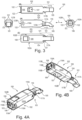
- FIG.3-7 show a preferred first embodiment of a chain link 100, which combines all three core aspects of the invention.
- the chain link 100 viewed in the longitudinal direction L, has a front or first longitudinal section 101 and a rear or second longitudinal section 102 designed to complement it.
- the chain link 100 also has two side parts 102A, 102B, which are designed in the manner of fork tabs and one in between Free space 103 form.
- the first longitudinal section 101 of an adjacent following chain link 100 designed as a male connector, can be inserted into the free space 103 and largely received, cf. FIG.5A-5B .
- the second longitudinal section 102 forms a corresponding female connector with the free space 103.
- Each chain link 100 is a one-piece injection molded part made of rigid, durable plastic.
- the longer second longitudinal section 102 forms a reinforced fuselage region 104, which can be designed as a solid body or with weight recesses and limits or closes the free space in the longitudinal direction L, cf. FIG.4B .
- the chain link 100 is in cross section (perpendicular to the longitudinal direction), see rear view FIG.3(E) , approximately square with compact dimensions, preferably with width ⁇ 25mm ⁇ height ⁇ 25mm.
- the length is a multiple of the height or width, but should be as short as possible for small radii in the deflection bend 7, for example in the range from 4 times to a maximum of 10 times the height.
- FIG.3(C) shows a top view of the outside of the chain link 100 facing away from the deflection axis A, see also FIG.5A .
- FIG.3(A) shows a bottom view of the inside of the chain link 100 facing the deflection axis A.
- the male longitudinal section 101 has a projection 105 in the front end region that projects transversely to the longitudinal direction L, like FIG.4B shows best.
- the approximately cuboid or plate-like projection 105 here is approximately aligned with the inside of the other longitudinal section 102 or the side parts 102A, 102B.
- the female longitudinal section 102 has a plate-like cross bridge 106 at the rear end region, which runs perpendicular to the longitudinal direction L and connects the side parts 102A, 102B in a stabilizing manner.
- the cross bridge 106 has approximately the wall thickness of the side parts 102A, 102B, for example approximately 10-25% of the height or width.
- the cross bridge 106 delimits a recess 107 on the inside in the longitudinal direction towards the front end region 101, which passes through here, that is, opens out from the free space 103 to the outside.
- the two cross bridges 106, 108 connect and stabilize the side parts 102A, 102B to form a box-shaped or circumferentially closed structure in cross section (cf. FIG.3(E) ) and in particular counteract any unwanted spreading of the side parts 102A, 102B at the rear end of the longitudinal section 102.
- FIG.5A (left), the projection 105 of a chain link 100 engages in the recess 107 of the chain link 100 connected to or following the chain strand and can engage the front side of the inside cross bridge 106 in order to transmit or initiate a tensile force, according to the first aspect of the invention .
- This effect is based on the FIG.7A-7B explained in more detail.
- the tongue-shaped first end region 101 In the extended relative position of two connected Chain links 100, as in FIG.7A shown, the tongue-shaped first end region 101, with a first stretch stop surface 110A facing the deflection axis A, rests flatly and in a force-transmitting manner on an opposite stretch stop surface 110B of the cross bridge 106 of the second end region 102.
- the stretch stop surfaces 110A, 110B effective in the extended position lie essentially parallel to the longitudinal direction L.
- an improved introduction of force is achieved in that the projection 105 interacts with an associated counter surface 112 of the cross bridge 106 by means of a contact surface 111 which is essentially perpendicular to the longitudinal direction L, in particular in the direction of the tensile force.
- a portion of the load in particular weight load, is introduced into the cross bridge 106 in the extended position as a force parallel to the longitudinal direction L and in the direction of a tensile force.
- FIG.7A show the direction in which the cross bridge 106 has a significantly larger dimension and flexural rigidity than in the height direction H, without having to increase its size. This results in a significantly more robust or long-lasting support chain 20 with equally compact external dimensions.
- FIG.7A The pivot point of the joint connection, indicated schematically by R, is displaced outwards (away from the deflection axis A), namely when the chain links 100, in particular the tongue-like first longitudinal section 101, deform under higher loads.
- R The pivot point of the joint connection
- Such a deformation is permitted as intended by suitable dimensioning, in particular of the first end region 101, until a corresponding shoulder or active surface 115A on the outside, in particular at the transition between the first longitudinal section 101 and the second longitudinal section 102, abuts on an abutment surface 115B of the opposite outside cross bridge 108, as in the area schematically designated W in FIG.7A shown.
- the cross bridge 108 When the effective surface 115A stops on the cross bridge 108 in this area W (not in FIG.7 shown), the cross bridge 108 thus forms an abutment.
- the lever length is defined by the end-side arrangement of the projection 105 and its contact surface 111 on the first longitudinal section 101.
- the projection 105 is arranged in the end front quarter of the first longitudinal section 101 and the inside cross bridge 106 is preferably arranged in the remote rear half of the second longitudinal section 102, as FIG.3 or.
- FIG.7A show.
- the leverage effect can be optimized by a suitable loose or single-value joint connection (see third aspect) or a joint connection with play in the height direction H.
- the introduction of the load via the contact surfaces 111, 112 can reach a predominant proportion.
- the first longitudinal section 101 is designed with a smaller cross section than the free space 103 in the second longitudinal section 102, as a comparison of FIG.3(D) with FIG.3(E) shows.
- the first longitudinal section 101 can be pivoted in the free space with little play and without abrasion edges in the longitudinal height plane LH and is dimensioned to be more easily deformable in this plane than the box-shaped reinforced second longitudinal section 102 in order to enable the interaction of the active surfaces 115A, 115B.
- the projection 105 with its contact surface 111 is designed such that it extends over the entire width of the first longitudinal section 101 (in cross section to the longitudinal direction L), as in FIG.3(B) and FIG.3(C) shown. Both can protrude with an overhang of approximately 10% of the height of the chain link 100 (dimension in height direction H). In this way, a comparatively large contact surface 111 is achieved with a compact design of the chain link 100.
- the recess 107 is designed as an opening from the free space 103 to the inside. The recess 107 can accommodate the projection 105 in a form-fitting manner in the extended position in order to bring about additional lateral stability of the deflection bend 7.
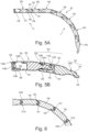
- the chain links 100 have cooperating arch stop surfaces 114A, 114B, as best shown in the comparison of FIG.5A with FIG.5B visible.
- a first sheet stop surface 114A is provided at the front end, which is in a completely angled position ( FIG.5A , right) interacts with an opposite second sheet stop surface 114B.
- This second sheet stop surface 114B is, according to the second aspect of the invention, provided on an additional crossbar 109 and facing open space 103.
- the crossbar 109 connects the side parts 102A, 102B in a stabilizing manner, similar to the crossbridge 108, and also merges in one piece into the fuselage area 104 and is thus reinforced by it against bending. This achieves a high level of stability of the stops in the arcuately curved relative position of the chain links 100 in the deflection bend 7.
- the first longitudinal section 101 has a projecting region 116 on the outside, which is in an arcuate position ( FIG.5A , right) engages in another recess between the crossbar 109 and the crossbridge 108.
- the tongue-shaped first longitudinal section 101 can tilt with the second longitudinal section 102 of the next chain link in an arcuate position, in that a further active surface 116A provided on the protruding region 116 engages or tilts on a further abutment surface of the outside cross bridge 108, as in FIG.5A illustrated.
- the support chain 20 transmits tensile force even in the deflection bend 7 or with fully angled chain links 100, that is, when the projection 105 is not in the tensile force-transmitting position of the extended position. This means that even in this position, no or a significantly reduced tensile force is transmitted via the joint connection.
- the projecting region 116 also forms a reinforcement of the front end region of the longitudinal section 101 with the projection 105, cf. FIG.7A .
- the proposed design with opposite cross bridges 106, 108 and the cross bar 109 is made possible, among other things, by the fact that the chain links 100 are connected to one another by plugging them together essentially in the longitudinal direction L, as shown FIG.5A-5B visible.
- the first longitudinal section 101 is designed in the form of a tongue-shaped tip that extends into the free space 103 can be inserted in the second longitudinal section 102 of an adjacent following chain link 100 in the longitudinal direction L.
- each chain link 100 has in one longitudinal section 101 two opposite locking pins 117A, 117B which project laterally in the longitudinal direction and which end laterally approximately flush with the side parts 102A, 102B.
- Each locking pin 117A, 117B can be locked with a corresponding locking recess 118A, 118B in the other longitudinal section 102.
- the locking recesses 118A, 118B are provided in the rear area of the side parts 102A, 102B on the side of the free space 103, here as openings in the side parts 102A, 102B. Since the chain links 100 are plugged together in the longitudinal direction L, the locking pins 117A, 117B have insertion bevels that taper obliquely in the longitudinal direction L to the tip of the first end region 101, as in FIG.3(B) and FIG.3(C) shown. Furthermore, each chain link 100 has insertion grooves 119A, 119B for the locking pins 117A, 117B to facilitate assembly. The insertion grooves 119A, 119B open into the recesses 118A, 118B starting from the insertion opening at the rear end of the end region 102 and are essentially aligned in the longitudinal direction L.
- the two side regions 102A, 102B of the second longitudinal section 102 each have a front end face 121 and a rear end face 122, which are opposite each other when there are adjacent chain links 100 and come into contact with the upper run 5 or the deflection bend 7 when the thrust force is applied, as can best be seen from the Longitudinal section through the side panels 102A in FIG.6 visible.
- the abutting end faces 121, 122 transmit the thrust force from one chain link 100 to the next.
- the tongue-shaped first longitudinal section 101 and the latching connection by means of latching pins 117A, 117B and corresponding latching recess 118A, 118B are preferably dimensioned with sufficient play in the longitudinal direction L so that no shear forces are transmitted here.
- FIG.7B In addition to the shape of the interacting end faces 121, 122, further illustrates the third, independent aspect of the invention, according to which the end faces 121, 122 of the two side parts 102A, 102B also form the articulated connection in the manner of a single-value (floating bearing) in the form of a tilting bearing.
- a joint area 123A on the front end face 121 is designed to be convex and a cooperating joint area 123B on the rear end face 122 is designed to be conjugately concave.
- the joint areas 123A, 123B can in particular be designed as circular cylinder surfaces with a radius defined by the dashed circular area R in FIG.7B is indicated schematically, with larger or smaller radii also being possible.
- the tilting bearing formed by the joint areas 123A, 123B provides a defined axis of rotation perpendicular to the LH plane (plane of the FIG.7B ) before.
- a significant advantage of this design is that the single-value joint cannot transmit any tensile force and cannot be overstressed by it.
- a degree of freedom in the height direction H is provided, which is particularly useful in combination with the optimized introduction of force according to the first aspect (cf. FIG.7A ) is advantageous.
- the loose joint connection based on the end faces 121, 122 offers advantages, among other things, with regard to freedom of design and surface pressure or force introduction of the thrust force.
- the recesses 118A, 118B run in a circular arc shape in the side regions 102A, 102B in the longitudinal height plane LH the pivot point of the joint areas 123A, 123B.
- the locking pins 117A, 117B can also be designed to be elongated and curved and run in the circular arc-shaped receptacles 118A, 118B in a similar way to a link guide or curved guide.
- the end faces 121, 122 form curved contact surfaces on both sides in the height direction, each adjacent to their joint area 123A, 123B, namely for the arcuate or stretched position.
- Each end face 121, 122 is divided into three functional areas in the height direction H: a stretching contact surface 125A or 125B, the joint area 123A or 123B and a sheet contact surface 124A or 124B.
- the stretch contact surfaces 125A, 125B work together in the stretched position, cf. FIG.7B , especially in the self-supporting strand 5.
- the arch contact surfaces 124A, 124B work together in the deflection arch 7 (arched position).
- the opposite sheet contact surfaces 124A, 124B and stretch contact surfaces 125A, 125B are shaped to be conjugated to one another, here curved approximately in the shape of a circular arc with a comparatively large radius, significantly larger than the joint areas 123A, 123B, but with center points that fall apart.
- FIG.8 shows an alternative embodiment of a chain link 200, which differs from the first in that the special joint connection according to the third aspect is not implemented, but rather a conventional joint connection with joint pin 240 and joint receptacle 242, which define a swivel joint with a predetermined axis of rotation. Otherwise, the essential features of the chain link 200 are essentially identical to that of FIG.3 .
- the first aspect of the invention is also implemented using a projection 205 on the first longitudinal section 201 and a cross bridge 206 on the second longitudinal section 202, as well as the second aspect with a further cross bridge 208 and an additional cross bar 209.
- the three aspects of the Invention can each be used advantageously on its own.
Landscapes
- Engineering & Computer Science (AREA)
- General Engineering & Computer Science (AREA)
- Mechanical Engineering (AREA)
- Architecture (AREA)
- Civil Engineering (AREA)
- Structural Engineering (AREA)
- Electric Cable Arrangement Between Relatively Moving Parts (AREA)
- Supports For Pipes And Cables (AREA)
- Details Of Indoor Wiring (AREA)
Claims (17)
- Chaîne de support (20) pour supporter un dispositif de guidage de conduites (1) avec une enveloppe flexible (10), la chaîne de support (20) pouvant prendre des positions étirées pour former des brins étirés (5, 6) ainsi qu'une position en forme d'arc pour former un arc de renvoi (7) et présentant à cet effet une pluralité de maillons de chaîne individuels (100; 200) avec une direction longitudinale (L), qui sont reliés entre eux de manière articulée, les maillons de chaîne (100; 200) comprennent chacun un premier tronçon longitudinal avant (101; 201) ainsi qu'un deuxième tronçon longitudinal arrière (102; 202) complémentaire à celui-ci, avec deux parties latérales (102A, 102B; 202A, 202B) et entre celles-ci un espace libre (103), dans lequel est disposé le premier tronçon longitudinal (101; 201) d'un maillon de chaîne adjacent, et les maillons de chaîne ont chacun un côté intérieur et un côté extérieur par rapport à l'arc de renvoi (7),
caractérisée en ce que- le premier tronçon longitudinal (101; 201) présente dans une zone d'extrémité et sur le côté intérieur une saillie (105; 205) faisant saillie transversalement à la direction longitudinale; et- le deuxième tronçon longitudinal (102; 202) présente sur le côté intérieur un pont transversal (106; 206) reliant les parties latérales, avec une surface de butée d'étirement (110B) pour la position étirée et un évidement (107; 207) adjacent au pont transversal (106; 206) sur le côté avant dans la direction longitudinale;- la saillie (105; 205) d'un maillon de chaîne s'engageant, en position étirée, dans l'évidement (107; 207) du maillon de chaîne suivant (100; 200) relié et, côté avant, contre son pont transversal (106; 206) côté intérieur. - Chaîne de support selon la revendication 1, caractérisée en ce que le deuxième tronçon longitudinal (102) présente sur le côté extérieur et dans une zone d'extrémité arrière une butée transversale, en particulier un pont transversal (108) côté extérieur reliant les parties latérales, qui fait face au côté extérieur du premier tronçon longitudinal (101) d'un maillon de chaîne adjacent comme butée (115B) pour la position étirée.
- Chaîne de support selon la revendication 1 ou 2, caractérisée en ce que la saillie (105) forme une surface d'appui (111) pour l'appui sur le pont transversal intérieur (106), qui est disposé sensiblement perpendiculairement à la direction longitudinale (L).
- Chaîne de support selon l'une quelconque des revendications 1 à 3, caractérisée en ce que les premier et deuxième tronçons longitudinaux (101, 102) présentent des surfaces de butée d'étirement (110A, 110B) coopérant en position étirée et en ce que la saillie (105) et le pont transversal (106) présentent des surfaces d'appui (111, 112) coopérant, qui sont sensiblement perpendiculaires aux surfaces de butée d'étirage (110A, 110B) et qui sont disposées de telle sorte que la saillie (105) d'un maillon de chaîne, en position étirée, s'applique par sa surface d'appui (111) contre la surface d'appui (112) du pont transversal (106) côté intérieur du maillon de chaîne suivant.
- Chaîne de support selon l'une quelconque des revendications 1 à 4, caractérisée en ce que la saillie (105; 205) s'étend sur toute la largeur de la première tronçon longitudinale en coupe transversale par rapport à la direction longitudinale et/ou la saillie dépasse d'au moins 5%, de préférence d'au moins 10% de la hauteur de construction du maillon de chaîne en coupe transversale par rapport à la direction longitudinale.
- Chaîne de support selon l'une quelconque des revendications 1 à 5, caractérisée en ce que la saillie (105; 205) est disposée dans le quart avant d'extrémité du premier tronçon longitudinal (101; 201) et le pont transversal intérieur (106; 206) est de préférence disposé dans la moitié arrière détournée du deuxième tronçon longitudinal (102; 202).
- Chaîne de support selon l'une des revendications 1 à 6, caractérisée en ce que l'évidement (107) forme une ouverture vers le côté intérieur partant de l'espace libre (103).
- Chaîne de support selon l'une quelconque des revendications 1 à 7, caractérisée en ce que chaque maillon de chaîne (100) comporte, dans son deuxième tronçon longitudinal, une barrette transversale extérieure (109) sur le côté extérieur, le pont transversale et la barrette transversale reliant les parties latérales en pontant l'espace libre, et en ce que le pont transversal (106) côté intérieur coopère, en position étirée, avec une surface de butée d'étirement (110A) côté intérieur du premier tronçon longitudinal, et le pont transversal (109) côté extérieur coopère, en position arquée, avec une surface de butée d'arc (114A) côté extérieur du premier tronçon longitudinal (101).
- Chaîne de support (20) pour supporter un dispositif de guidage de conduites (1) avec une enveloppe flexible (10), en particulier selon la revendication 1, la chaîne de support (20) pouvant prendre des positions étirées pour former des brins étirés (5, 6) ainsi qu'une position en forme d'arc pour former un arc de renvoi (7) et comprenant à cet effet une pluralité de maillons de chaîne individuels (100; 200) avec une direction longitudinale (L), qui sont reliés entre eux de manière articulée, les maillons de chaîne comprenant chacun un premier tronçon longitudinal (101; 201) ainsi qu'un deuxième tronçon longitudinal (201; 202) complémentaire de celui-ci avec deux parties latérales (102A, 102B; 220A, 202B) et entre celles-ci un espace libre (103; 203), dans lequel est disposé le premier tronçon longitudinal d'un maillon de chaîne suivant adjacent et les maillons de chaîne (100; 200) ont chacun un côté intérieur et un côté extérieur, chaque maillon de chaîne (100; 200) ayant dans sa deuxième tronçon longitudinale (102; 202), sur le côté extérieur, une liaison transversale extérieure (109; 209) et, sur le côté intérieur, une liaison transversale intérieure (106; 206) qui pontent l'espace libre (103; 203) et relient les parties latérales (102A, 102B; 202A, 202B), et la liaison transversale côté intérieur (106; 206) coopérant, en position étirée, avec une surface de butée d'étirement côté intérieur (110A, 210A) de la première tronçon longitudinale, et la liaison transversale côté extérieur (109; 209) coopérant, en position arquée, avec une surface de butée d'arc côté extérieur (114A, 214A) de la première tronçon longitudinale (101; 201).
- Chaîne de support selon la revendication 9, caractérisée en ce que la liaison transversale côté extérieur est réalisée sous forme de barrette transversale (109; 209) et la liaison transversale côté intérieur sous forme de pont transversal (106; 206);
et de préférence chaque maillon de chaîne (100; 200) présente dans sa deuxième tronçon longitudinale sur le côté extérieur dans une zone avant la barrette transversale (109; 209) et dans une zone d'extrémité arrière un pont transversal (108; 208) côté extérieur, la première tronçon longitudinale (101; 201) présentant sur le côté extérieur une zone en saillie (116; 216) qui, en position arquée, s'engage entre la barrette transversale (109; 209) et le pont transversal côté extérieur (108; 208), et la première tronçon longitudinale se coinçant de préférence avec la deuxième tronçon longitudinale en position arquée (116A, 116B). - Chaîne de support selon l'une quelconque des revendications 1 à 10 précédentes, en particulier selon la revendication 9, caractérisée en ce que le premier tronçon longitudinal (101; 201) peut être inséré dans l'espace libre (103; 203) dans le deuxième tronçon longitudinal (102; 202) d'un maillon de chaîne suivant adjacent dans la direction longitudinale (L).
- Chaîne de support selon l'une quelconque des revendications 1 à 11 précédentes, en particulier selon la revendication 11, dans laquelle les tronçons longitudinaux sont conçus pour former une liaison par encliquetage anti-desserrage dans la direction longitudinale, chaque maillon de chaîne comporte, dans l'un des tronçons longitudinaux, deux tenons (117A, 117B) opposés et faisant saillie latéralement par rapport à la direction longitudinale, chaque tenon étant engagé dans un évidement correspondant (118A, 118B) dans l'autre tronçon longitudinale, caractérisée en ce que les tenons (117A, 117B) présentent des chanfreins d'introduction se terminant en oblique dans la direction longitudinale, de préférence chaque maillon de chaîne présentant des rainures d'introduction (119A, 119B) pour les tenons (117A, 117B) débouchant dans les évidements (118A, 118B), qui s'étendent essentiellement dans la direction longitudinale.
- Chaîne de support (20) pour supporter un dispositif de guidage de conduites (1) avec une enveloppe flexible (10), la chaîne de support (20) pouvant prendre des positions étirées pour former des brins étirés (5, 6) ainsi qu'une position en forme d'arc pour former un arc de renvoi (7) et présentant à cet effet une pluralité de maillons de chaîne individuels (100) avec une direction longitudinale (L), qui sont reliés entre eux de manière articulée, les maillons de chaîne (100) comprenant chacun un premier tronçon longitudinal avant (101) ainsi qu'un deuxième tronçon longitudinal arrière (102) complémentaire à celui-ci, avec deux parties latérales (102A, 102B) et entre celles-ci un espace libre (103), dans lequel est disposé le premier tronçon longitudinal (101) d'un maillon de chaîne suivant adjacent, et les deux parties latérales (102A, 102B) du deuxième tronçon longitudinale ayant chacune une surface frontale avant (121) et une surface frontale arrière (122) qui sont opposées en cas des maillons de chaîne adjacents, la surface frontale avant (121) formant une zone d'articulation (123A) et la surface frontale arrière (122) formant une zone d'articulation complémentaire (123B), de sorte que les zones d'articulation respectives de la surface frontale avant (121) d'un maillon de chaîne et de la surface frontale arrière (102) d'un maillon de chaîne adjacent coopèrent pour relier de manière articulée ces deux maillons de chaîne (100) et définissent un axe de pivotement pour faire pivoter les deux maillons de chaîne lors d'une charge de poussée de la chaîne de support, de préférence en outre dans lequel- la zone d'articulation (123A) de la surface frontale avant (121) est de forme convexe et la zone d'articulation (123B) de la surface frontale arrière est de forme concave, et/ou- les zones d'articulation sont réalisées pour une liaison articulée pivotante avec un axe de pivotement perpendiculaire à la direction longitudinale.
- Chaîne de support selon la revendication 13, caractérisée en ce que les surfaces frontales forment, dans le sens de la hauteur, au moins d'un côté, de préférence des deux côtés par rapport à la zone d'articulation, respectivement une surface d'appui (124A, 124B), de préférence une surface d'appui courbée, pour la position arquée ou étirée.
- Chaîne de support selon l'une quelconque des revendications précédentes 1 à 14, en particulier selon la revendication 14, dans laquelle chaque maillon de la chaîne comporte, dans l'un des tronçons longitudinaux, deux tenons (117A, 117B) opposés et faisant saillie latéralement par rapport à la direction longitudinale, chaque tenon pouvant être enclenché dans un évidement correspondant (118A, 118B) ménagé dans l'autre tronçon longitudinal, caractérisée en ce que les évidements (118A, 118B) s'étendent en arc de cercle dans un plan longitudinal dans les parties latérales.
- Chaîne de support selon l'une des revendications 1 à 15, caractérisée en ce que le maillon de chaîne est fabriqué d'une seule pièce en matière plastique, notamment par moulage par injection.
- Dispositif de guidage de conduites (1), en particulier pour des applications en salle blanche, pour le guidage protégé de conduites d'alimentation (3) telles que des câbles, des tuyaux ou similaires entre deux points de raccordement (2, 4), dont au moins un est mobile par rapport à l'autre, le dispositif de guidage de conduites présentant une direction longitudinale (L) et pouvant être déplacé en va-et-vient en formant deux brins (5, 6) et un arc de renvoi (7), comprenant:- une enveloppe flexible (10) avec un certain nombre de canaux de réception (12) disposés les uns à côté des autres et s'étendant dans la direction longitudinale pour respectivement au moins une conduite d'alimentation (3), etau moins une chaîne de support (20) qui peut être disposée dans un canal de réception (12) pour supporter le dispositif de guidage de conduite (1), ladite au moins une chaîne de support étant une chaîne de support selon l'une des revendications précédentes.
Applications Claiming Priority (2)
| Application Number | Priority Date | Filing Date | Title |
|---|---|---|---|
| DE202019106979.1U DE202019106979U1 (de) | 2019-12-13 | 2019-12-13 | Leitungsführungsvorrichtung für Reinraumanwendungen sowie Stützkette und Kettenglied hierfür |
| PCT/EP2020/085861 WO2021116467A1 (fr) | 2019-12-13 | 2020-12-11 | Dispositif de guidage de ligne pour des applications de salle blanche, ainsi que chaîne de support et maillon de chaîne pour celui-ci |
Publications (2)
| Publication Number | Publication Date |
|---|---|
| EP4073894A1 EP4073894A1 (fr) | 2022-10-19 |
| EP4073894B1 true EP4073894B1 (fr) | 2023-11-01 |
Family
ID=74141448
Family Applications (1)
| Application Number | Title | Priority Date | Filing Date |
|---|---|---|---|
| EP20838372.9A Active EP4073894B1 (fr) | 2019-12-13 | 2020-12-11 | Dispositif de guidage de ligne pour des applications de salle blanche, ainsi que chaîne de support et maillon de chaîne pour celui-ci |
Country Status (11)
| Country | Link |
|---|---|
| US (1) | US12160092B2 (fr) |
| EP (1) | EP4073894B1 (fr) |
| JP (1) | JP7681596B2 (fr) |
| KR (1) | KR102903818B1 (fr) |
| CN (1) | CN114868316A (fr) |
| BR (1) | BR112022008844A2 (fr) |
| CA (1) | CA3159741A1 (fr) |
| DE (1) | DE202019106979U1 (fr) |
| MX (1) | MX2022006888A (fr) |
| MY (1) | MY208724A (fr) |
| WO (1) | WO2021116467A1 (fr) |
Families Citing this family (4)
| Publication number | Priority date | Publication date | Assignee | Title |
|---|---|---|---|---|
| DE202020102090U1 (de) | 2020-04-15 | 2021-05-25 | Igus Gmbh | Leitungsführungsvorrichtung und modulare Endbefestigungen mit flexibler Umhüllung für Reinraumanwendungen |
| DE102022109963A1 (de) | 2022-04-25 | 2023-10-26 | Igus Gmbh | Verfahren und System zur indirekten Erkennung von Verschleiß einer Leitungsführungseinrichtung bzw. Energieführungskette |
| DE202022102217U1 (de) | 2022-04-25 | 2023-07-26 | Igus Gmbh | Leitungsführungsvorrichtung und Stützkette für Reinraumanwendungen |
| CN115899173B (zh) * | 2022-12-28 | 2025-06-06 | 上海慷梭汽车电子科技有限公司 | 高负载拖链 |
Family Cites Families (22)
| Publication number | Priority date | Publication date | Assignee | Title |
|---|---|---|---|---|
| DE1281350B (de) * | 1967-09-06 | 1968-10-24 | Ruberg & Renner G M B H | Transportkette |
| DE1985806U (de) | 1968-01-08 | 1968-05-22 | Karl Moll | Kettenglied, insbesondere fuer transportketten. |
| DE2141709A1 (de) * | 1971-08-20 | 1973-03-01 | Ruberg & Renner Gmbh | Gelenkkette |
| JPH0144837Y2 (fr) * | 1986-03-12 | 1989-12-25 | ||
| DE20101656U1 (de) * | 2001-01-30 | 2001-04-19 | Igus Spritzgußteile für die Industrie GmbH, 51147 Köln | Führungsrinne |
| JP2005147233A (ja) * | 2003-11-13 | 2005-06-09 | Tsubakimoto Chain Co | ケーブル保護案内装置 |
| DE202004001318U1 (de) * | 2004-01-28 | 2004-05-13 | Pöllet, Wilfried | Kettenartige Kabelführung mit wieder lösbar beweglich miteinander verbundenen Segmenten |
| JP4721043B2 (ja) | 2005-06-14 | 2011-07-13 | 住友電装株式会社 | スライドドアのハーネスガイド |
| JP4302752B2 (ja) * | 2007-05-02 | 2009-07-29 | 株式会社椿本チエイン | ケーブル類保護案内装置 |
| JP4658221B1 (ja) * | 2009-11-26 | 2011-03-23 | 株式会社椿本チエイン | 多関節型ケーブル類保護案内装置 |
| JP4749494B1 (ja) | 2010-04-02 | 2011-08-17 | 株式会社椿本チエイン | ケーブル類保護案内用多関節支持部材 |
| FR2962513B1 (fr) * | 2010-07-09 | 2012-08-10 | Trw Automotive Elect & Components Gmbh | Composant pour un clip de fixation et clip de fixation |
| JP5414704B2 (ja) | 2011-01-21 | 2014-02-12 | 株式会社椿本チエイン | 多関節型ケーブル類保護案内装置 |
| JP5127943B2 (ja) * | 2011-02-10 | 2013-01-23 | サムウォン アクト インコーポレイテッド | 多関節型ケーブル類保護案内装置 |
| JP5079894B2 (ja) * | 2011-02-15 | 2012-11-21 | 株式会社椿本チエイン | 多関節型ケーブル類保護案内装置 |
| DE102011111449B4 (de) | 2011-08-30 | 2014-07-17 | Carl Freudenberg Kg | Klemmmverbindung zur Befestigung von plattenförmigen Bauelementen insbesondere von Solarmodulen |
| KR101300068B1 (ko) | 2011-12-23 | 2013-08-23 | 신무현 | 전송라인용 슬리브의 지지모듈 |
| DE102012101216B4 (de) * | 2012-02-15 | 2025-06-12 | Hettich-Heinze Gmbh & Co. Kg | Schiebetürbeschlag |
| DE202013101203U1 (de) | 2013-03-20 | 2013-03-26 | Igus Gmbh | Energieführungskette insbesondere für Reinraumanwendungen |
| JP6317291B2 (ja) | 2015-04-27 | 2018-04-25 | 株式会社椿本チエイン | ケーブル類保護案内装置及び固定部材 |
| KR101923416B1 (ko) * | 2016-12-14 | 2018-11-29 | (주)한신체인 | 자켓 타입의 로보체인 |
| KR101857454B1 (ko) * | 2017-05-19 | 2018-05-15 | 성호철 | 다관절 지지부재 |
-
2019
- 2019-12-13 DE DE202019106979.1U patent/DE202019106979U1/de active Active
-
2020
- 2020-12-11 CA CA3159741A patent/CA3159741A1/fr active Pending
- 2020-12-11 MY MYPI2022002991A patent/MY208724A/en unknown
- 2020-12-11 US US17/757,187 patent/US12160092B2/en active Active
- 2020-12-11 KR KR1020227020894A patent/KR102903818B1/ko active Active
- 2020-12-11 JP JP2022535877A patent/JP7681596B2/ja active Active
- 2020-12-11 MX MX2022006888A patent/MX2022006888A/es unknown
- 2020-12-11 WO PCT/EP2020/085861 patent/WO2021116467A1/fr not_active Ceased
- 2020-12-11 BR BR112022008844A patent/BR112022008844A2/pt unknown
- 2020-12-11 EP EP20838372.9A patent/EP4073894B1/fr active Active
- 2020-12-11 CN CN202080086234.6A patent/CN114868316A/zh active Pending
Also Published As
| Publication number | Publication date |
|---|---|
| BR112022008844A2 (pt) | 2022-08-16 |
| JP2023510497A (ja) | 2023-03-14 |
| KR20220110230A (ko) | 2022-08-05 |
| DE202019106979U1 (de) | 2021-01-18 |
| CA3159741A1 (fr) | 2021-06-17 |
| WO2021116467A1 (fr) | 2021-06-17 |
| EP4073894A1 (fr) | 2022-10-19 |
| US20230006432A1 (en) | 2023-01-05 |
| MY208724A (en) | 2025-05-27 |
| CN114868316A (zh) | 2022-08-05 |
| US12160092B2 (en) | 2024-12-03 |
| JP7681596B2 (ja) | 2025-05-22 |
| KR102903818B1 (ko) | 2025-12-26 |
| MX2022006888A (es) | 2022-09-23 |
Similar Documents
| Publication | Publication Date | Title |
|---|---|---|
| EP4073894B1 (fr) | Dispositif de guidage de ligne pour des applications de salle blanche, ainsi que chaîne de support et maillon de chaîne pour celui-ci | |
| EP1108157B1 (fr) | Chaine de guidage de l'energie pour guider des conducteurs dotee de maillons mobile dans l'espace | |
| EP3054192B1 (fr) | Chaine porte-cables avec elements d'articulation deformables | |
| EP1975093B1 (fr) | Chaîne d'alimentation à flexion latérale dotée d'articulations extérieures et intérieures | |
| EP4158223B1 (fr) | Chaîne porte-câbles à éléments de raccordement articulés flexibles, ainsi que pattes latérales et élément de raccordement articulé approprié | |
| DE102004043412A1 (de) | Schutz- und Führungsvorrichtung für ein Kabel oder dergleichen | |
| DE102012112042B4 (de) | Geräuscharme Kette | |
| WO2006108401A1 (fr) | Dispositif de cablage et systeme comprenant un dispositif de cablage et un dispositif de retenue logeant ledit dispositif de cablage | |
| DE202015100479U1 (de) | Kettenglied und Handhabungskette mit Kettenglied | |
| EP3894721B1 (fr) | Chaîne de transport d'énergie avec des flasques en matière plastique à stabilisation latérale | |
| EP2283249A1 (fr) | Fourche à anneau de raccourcissement pour raccourcir un brin de chaîne | |
| EP3253993A1 (fr) | Maillon de chaîne et chaîne circulaire munie de maillons | |
| EP1744079A1 (fr) | Chaîne rigide | |
| EP4259951B1 (fr) | Chaînes porte-câbles pour déplacements importants, comprenant notamment des galets de roulement | |
| DE202021004122U1 (de) | Energieführungsketten für lange Verfahrwege, insbesondere mit Laufrollen | |
| DE202017105244U1 (de) | Energieführungskette mit in die Gelenkverbindungen integrierten Schwenkwinkel-Anschlägen und entsprechende Kettenlaschen | |
| WO2026078013A1 (fr) | Chaîne porte-câbles et flasque latéral à stabilisation latérale | |
| WO2007121957A1 (fr) | Chaîne transporteuse | |
| EP4515645A1 (fr) | Dispositif de guidage de ligne et chaîne de support pour applications en salle blanche | |
| EP1705401A2 (fr) | Maillon pour une chaîne porteuse de lignes de transport d'énergie | |
| DE20002500U1 (de) | Energieführungskette | |
| DE19739782A1 (de) | Kettenglied mit verschwenkbaren Stegen | |
| DE202024000781U1 (de) | Energieführungskette für hohe Zugkräfte und/oder mit Verliersicherung | |
| DE202024105778U1 (de) | Energieführungskette für lange Verfahrwege sowie Kettenglied und Lasche hierfür | |
| DE202015005140U1 (de) | Energieführungskette und Quersteg hierzu |
Legal Events
| Date | Code | Title | Description |
|---|---|---|---|
| STAA | Information on the status of an ep patent application or granted ep patent |
Free format text: STATUS: UNKNOWN |
|
| STAA | Information on the status of an ep patent application or granted ep patent |
Free format text: STATUS: THE INTERNATIONAL PUBLICATION HAS BEEN MADE |
|
| PUAI | Public reference made under article 153(3) epc to a published international application that has entered the european phase |
Free format text: ORIGINAL CODE: 0009012 |
|
| STAA | Information on the status of an ep patent application or granted ep patent |
Free format text: STATUS: REQUEST FOR EXAMINATION WAS MADE |
|
| 17P | Request for examination filed |
Effective date: 20220707 |
|
| AK | Designated contracting states |
Kind code of ref document: A1 Designated state(s): AL AT BE BG CH CY CZ DE DK EE ES FI FR GB GR HR HU IE IS IT LI LT LU LV MC MK MT NL NO PL PT RO RS SE SI SK SM TR |
|
| DAV | Request for validation of the european patent (deleted) | ||
| DAX | Request for extension of the european patent (deleted) | ||
| GRAP | Despatch of communication of intention to grant a patent |
Free format text: ORIGINAL CODE: EPIDOSNIGR1 |
|
| STAA | Information on the status of an ep patent application or granted ep patent |
Free format text: STATUS: GRANT OF PATENT IS INTENDED |
|
| INTG | Intention to grant announced |
Effective date: 20230524 |
|
| P01 | Opt-out of the competence of the unified patent court (upc) registered |
Effective date: 20230526 |
|
| GRAS | Grant fee paid |
Free format text: ORIGINAL CODE: EPIDOSNIGR3 |
|
| GRAA | (expected) grant |
Free format text: ORIGINAL CODE: 0009210 |
|
| STAA | Information on the status of an ep patent application or granted ep patent |
Free format text: STATUS: THE PATENT HAS BEEN GRANTED |
|
| AK | Designated contracting states |
Kind code of ref document: B1 Designated state(s): AL AT BE BG CH CY CZ DE DK EE ES FI FR GB GR HR HU IE IS IT LI LT LU LV MC MK MT NL NO PL PT RO RS SE SI SK SM TR |
|
| REG | Reference to a national code |
Ref country code: GB Ref legal event code: FG4D Free format text: NOT ENGLISH |
|
| REG | Reference to a national code |
Ref country code: CH Ref legal event code: EP |
|
| REG | Reference to a national code |
Ref country code: DE Ref legal event code: R096 Ref document number: 502020005902 Country of ref document: DE |
|
| REG | Reference to a national code |
Ref country code: IE Ref legal event code: FG4D Free format text: LANGUAGE OF EP DOCUMENT: GERMAN |
|
| REG | Reference to a national code |
Ref country code: LT Ref legal event code: MG9D |
|
| REG | Reference to a national code |
Ref country code: NL Ref legal event code: MP Effective date: 20231101 |
|
| PG25 | Lapsed in a contracting state [announced via postgrant information from national office to epo] |
Ref country code: GR Free format text: LAPSE BECAUSE OF FAILURE TO SUBMIT A TRANSLATION OF THE DESCRIPTION OR TO PAY THE FEE WITHIN THE PRESCRIBED TIME-LIMIT Effective date: 20240202 |
|
| PG25 | Lapsed in a contracting state [announced via postgrant information from national office to epo] |
Ref country code: IS Free format text: LAPSE BECAUSE OF FAILURE TO SUBMIT A TRANSLATION OF THE DESCRIPTION OR TO PAY THE FEE WITHIN THE PRESCRIBED TIME-LIMIT Effective date: 20240301 |
|
| PG25 | Lapsed in a contracting state [announced via postgrant information from national office to epo] |
Ref country code: LT Free format text: LAPSE BECAUSE OF FAILURE TO SUBMIT A TRANSLATION OF THE DESCRIPTION OR TO PAY THE FEE WITHIN THE PRESCRIBED TIME-LIMIT Effective date: 20231101 |
|
| PG25 | Lapsed in a contracting state [announced via postgrant information from national office to epo] |
Ref country code: NL Free format text: LAPSE BECAUSE OF FAILURE TO SUBMIT A TRANSLATION OF THE DESCRIPTION OR TO PAY THE FEE WITHIN THE PRESCRIBED TIME-LIMIT Effective date: 20231101 |
|
| PG25 | Lapsed in a contracting state [announced via postgrant information from national office to epo] |
Ref country code: ES Free format text: LAPSE BECAUSE OF FAILURE TO SUBMIT A TRANSLATION OF THE DESCRIPTION OR TO PAY THE FEE WITHIN THE PRESCRIBED TIME-LIMIT Effective date: 20231101 |
|
| PG25 | Lapsed in a contracting state [announced via postgrant information from national office to epo] |
Ref country code: NL Free format text: LAPSE BECAUSE OF FAILURE TO SUBMIT A TRANSLATION OF THE DESCRIPTION OR TO PAY THE FEE WITHIN THE PRESCRIBED TIME-LIMIT Effective date: 20231101 Ref country code: LT Free format text: LAPSE BECAUSE OF FAILURE TO SUBMIT A TRANSLATION OF THE DESCRIPTION OR TO PAY THE FEE WITHIN THE PRESCRIBED TIME-LIMIT Effective date: 20231101 Ref country code: IS Free format text: LAPSE BECAUSE OF FAILURE TO SUBMIT A TRANSLATION OF THE DESCRIPTION OR TO PAY THE FEE WITHIN THE PRESCRIBED TIME-LIMIT Effective date: 20240301 Ref country code: GR Free format text: LAPSE BECAUSE OF FAILURE TO SUBMIT A TRANSLATION OF THE DESCRIPTION OR TO PAY THE FEE WITHIN THE PRESCRIBED TIME-LIMIT Effective date: 20240202 Ref country code: ES Free format text: LAPSE BECAUSE OF FAILURE TO SUBMIT A TRANSLATION OF THE DESCRIPTION OR TO PAY THE FEE WITHIN THE PRESCRIBED TIME-LIMIT Effective date: 20231101 Ref country code: BG Free format text: LAPSE BECAUSE OF FAILURE TO SUBMIT A TRANSLATION OF THE DESCRIPTION OR TO PAY THE FEE WITHIN THE PRESCRIBED TIME-LIMIT Effective date: 20240201 Ref country code: PT Free format text: LAPSE BECAUSE OF FAILURE TO SUBMIT A TRANSLATION OF THE DESCRIPTION OR TO PAY THE FEE WITHIN THE PRESCRIBED TIME-LIMIT Effective date: 20240301 |
|
| PG25 | Lapsed in a contracting state [announced via postgrant information from national office to epo] |
Ref country code: SE Free format text: LAPSE BECAUSE OF FAILURE TO SUBMIT A TRANSLATION OF THE DESCRIPTION OR TO PAY THE FEE WITHIN THE PRESCRIBED TIME-LIMIT Effective date: 20231101 Ref country code: RS Free format text: LAPSE BECAUSE OF FAILURE TO SUBMIT A TRANSLATION OF THE DESCRIPTION OR TO PAY THE FEE WITHIN THE PRESCRIBED TIME-LIMIT Effective date: 20231101 Ref country code: PL Free format text: LAPSE BECAUSE OF FAILURE TO SUBMIT A TRANSLATION OF THE DESCRIPTION OR TO PAY THE FEE WITHIN THE PRESCRIBED TIME-LIMIT Effective date: 20231101 Ref country code: NO Free format text: LAPSE BECAUSE OF FAILURE TO SUBMIT A TRANSLATION OF THE DESCRIPTION OR TO PAY THE FEE WITHIN THE PRESCRIBED TIME-LIMIT Effective date: 20240201 Ref country code: LV Free format text: LAPSE BECAUSE OF FAILURE TO SUBMIT A TRANSLATION OF THE DESCRIPTION OR TO PAY THE FEE WITHIN THE PRESCRIBED TIME-LIMIT Effective date: 20231101 Ref country code: HR Free format text: LAPSE BECAUSE OF FAILURE TO SUBMIT A TRANSLATION OF THE DESCRIPTION OR TO PAY THE FEE WITHIN THE PRESCRIBED TIME-LIMIT Effective date: 20231101 |
|
| PG25 | Lapsed in a contracting state [announced via postgrant information from national office to epo] |
Ref country code: DK Free format text: LAPSE BECAUSE OF FAILURE TO SUBMIT A TRANSLATION OF THE DESCRIPTION OR TO PAY THE FEE WITHIN THE PRESCRIBED TIME-LIMIT Effective date: 20231101 |
|
| PG25 | Lapsed in a contracting state [announced via postgrant information from national office to epo] |
Ref country code: CZ Free format text: LAPSE BECAUSE OF FAILURE TO SUBMIT A TRANSLATION OF THE DESCRIPTION OR TO PAY THE FEE WITHIN THE PRESCRIBED TIME-LIMIT Effective date: 20231101 |
|
| PG25 | Lapsed in a contracting state [announced via postgrant information from national office to epo] |
Ref country code: SK Free format text: LAPSE BECAUSE OF FAILURE TO SUBMIT A TRANSLATION OF THE DESCRIPTION OR TO PAY THE FEE WITHIN THE PRESCRIBED TIME-LIMIT Effective date: 20231101 |
|
| PG25 | Lapsed in a contracting state [announced via postgrant information from national office to epo] |
Ref country code: SM Free format text: LAPSE BECAUSE OF FAILURE TO SUBMIT A TRANSLATION OF THE DESCRIPTION OR TO PAY THE FEE WITHIN THE PRESCRIBED TIME-LIMIT Effective date: 20231101 Ref country code: SK Free format text: LAPSE BECAUSE OF FAILURE TO SUBMIT A TRANSLATION OF THE DESCRIPTION OR TO PAY THE FEE WITHIN THE PRESCRIBED TIME-LIMIT Effective date: 20231101 Ref country code: EE Free format text: LAPSE BECAUSE OF FAILURE TO SUBMIT A TRANSLATION OF THE DESCRIPTION OR TO PAY THE FEE WITHIN THE PRESCRIBED TIME-LIMIT Effective date: 20231101 Ref country code: DK Free format text: LAPSE BECAUSE OF FAILURE TO SUBMIT A TRANSLATION OF THE DESCRIPTION OR TO PAY THE FEE WITHIN THE PRESCRIBED TIME-LIMIT Effective date: 20231101 Ref country code: CZ Free format text: LAPSE BECAUSE OF FAILURE TO SUBMIT A TRANSLATION OF THE DESCRIPTION OR TO PAY THE FEE WITHIN THE PRESCRIBED TIME-LIMIT Effective date: 20231101 |
|
| REG | Reference to a national code |
Ref country code: DE Ref legal event code: R097 Ref document number: 502020005902 Country of ref document: DE |
|
| PG25 | Lapsed in a contracting state [announced via postgrant information from national office to epo] |
Ref country code: LU Free format text: LAPSE BECAUSE OF NON-PAYMENT OF DUE FEES Effective date: 20231211 |
|
| PG25 | Lapsed in a contracting state [announced via postgrant information from national office to epo] |
Ref country code: MC Free format text: LAPSE BECAUSE OF FAILURE TO SUBMIT A TRANSLATION OF THE DESCRIPTION OR TO PAY THE FEE WITHIN THE PRESCRIBED TIME-LIMIT Effective date: 20231101 |
|
| REG | Reference to a national code |
Ref country code: BE Ref legal event code: MM Effective date: 20231231 |
|
| PG25 | Lapsed in a contracting state [announced via postgrant information from national office to epo] |
Ref country code: MC Free format text: LAPSE BECAUSE OF FAILURE TO SUBMIT A TRANSLATION OF THE DESCRIPTION OR TO PAY THE FEE WITHIN THE PRESCRIBED TIME-LIMIT Effective date: 20231101 Ref country code: LU Free format text: LAPSE BECAUSE OF NON-PAYMENT OF DUE FEES Effective date: 20231211 |
|
| PLBE | No opposition filed within time limit |
Free format text: ORIGINAL CODE: 0009261 |
|
| STAA | Information on the status of an ep patent application or granted ep patent |
Free format text: STATUS: NO OPPOSITION FILED WITHIN TIME LIMIT |
|
| 26N | No opposition filed |
Effective date: 20240802 |
|
| REG | Reference to a national code |
Ref country code: IE Ref legal event code: MM4A |
|
| PG25 | Lapsed in a contracting state [announced via postgrant information from national office to epo] |
Ref country code: IE Free format text: LAPSE BECAUSE OF NON-PAYMENT OF DUE FEES Effective date: 20231211 |
|
| PG25 | Lapsed in a contracting state [announced via postgrant information from national office to epo] |
Ref country code: BE Free format text: LAPSE BECAUSE OF NON-PAYMENT OF DUE FEES Effective date: 20231231 |
|
| PG25 | Lapsed in a contracting state [announced via postgrant information from national office to epo] |
Ref country code: SI Free format text: LAPSE BECAUSE OF FAILURE TO SUBMIT A TRANSLATION OF THE DESCRIPTION OR TO PAY THE FEE WITHIN THE PRESCRIBED TIME-LIMIT Effective date: 20231101 |
|
| PG25 | Lapsed in a contracting state [announced via postgrant information from national office to epo] |
Ref country code: SI Free format text: LAPSE BECAUSE OF FAILURE TO SUBMIT A TRANSLATION OF THE DESCRIPTION OR TO PAY THE FEE WITHIN THE PRESCRIBED TIME-LIMIT Effective date: 20231101 Ref country code: IE Free format text: LAPSE BECAUSE OF NON-PAYMENT OF DUE FEES Effective date: 20231211 Ref country code: BE Free format text: LAPSE BECAUSE OF NON-PAYMENT OF DUE FEES Effective date: 20231231 |
|
| PGFP | Annual fee paid to national office [announced via postgrant information from national office to epo] |
Ref country code: CH Payment date: 20250101 Year of fee payment: 5 |
|
| PG25 | Lapsed in a contracting state [announced via postgrant information from national office to epo] |
Ref country code: RO Free format text: LAPSE BECAUSE OF FAILURE TO SUBMIT A TRANSLATION OF THE DESCRIPTION OR TO PAY THE FEE WITHIN THE PRESCRIBED TIME-LIMIT Effective date: 20231101 |
|
| PG25 | Lapsed in a contracting state [announced via postgrant information from national office to epo] |
Ref country code: FI Free format text: LAPSE BECAUSE OF FAILURE TO SUBMIT A TRANSLATION OF THE DESCRIPTION OR TO PAY THE FEE WITHIN THE PRESCRIBED TIME-LIMIT Effective date: 20231101 |
|
| PG25 | Lapsed in a contracting state [announced via postgrant information from national office to epo] |
Ref country code: CY Free format text: LAPSE BECAUSE OF FAILURE TO SUBMIT A TRANSLATION OF THE DESCRIPTION OR TO PAY THE FEE WITHIN THE PRESCRIBED TIME-LIMIT; INVALID AB INITIO Effective date: 20201211 |
|
| PG25 | Lapsed in a contracting state [announced via postgrant information from national office to epo] |
Ref country code: HU Free format text: LAPSE BECAUSE OF FAILURE TO SUBMIT A TRANSLATION OF THE DESCRIPTION OR TO PAY THE FEE WITHIN THE PRESCRIBED TIME-LIMIT; INVALID AB INITIO Effective date: 20201211 |
|
| GBPC | Gb: european patent ceased through non-payment of renewal fee |
Effective date: 20241211 |
|
| PG25 | Lapsed in a contracting state [announced via postgrant information from national office to epo] |
Ref country code: GB Free format text: LAPSE BECAUSE OF NON-PAYMENT OF DUE FEES Effective date: 20241211 |
|
| PG25 | Lapsed in a contracting state [announced via postgrant information from national office to epo] |
Ref country code: TR Free format text: LAPSE BECAUSE OF FAILURE TO SUBMIT A TRANSLATION OF THE DESCRIPTION OR TO PAY THE FEE WITHIN THE PRESCRIBED TIME-LIMIT Effective date: 20231101 |
|
| REG | Reference to a national code |
Ref country code: CH Ref legal event code: U11 Free format text: ST27 STATUS EVENT CODE: U-0-0-U10-U11 (AS PROVIDED BY THE NATIONAL OFFICE) Effective date: 20260101 |
|
| PGFP | Annual fee paid to national office [announced via postgrant information from national office to epo] |
Ref country code: AT Payment date: 20260113 Year of fee payment: 5 |
|
| PGFP | Annual fee paid to national office [announced via postgrant information from national office to epo] |
Ref country code: FR Payment date: 20251217 Year of fee payment: 6 |
|
| REG | Reference to a national code |
Ref country code: DE Ref legal event code: R081 Ref document number: 502020005902 Country of ref document: DE Owner name: IGUS SE & CO. KG, DE Free format text: FORMER OWNER: IGUS GMBH, 51147 KOELN, DE |
|
| PGFP | Annual fee paid to national office [announced via postgrant information from national office to epo] |
Ref country code: DE Payment date: 20260225 Year of fee payment: 6 |
|
| PGFP | Annual fee paid to national office [announced via postgrant information from national office to epo] |
Ref country code: IT Payment date: 20251231 Year of fee payment: 6 |