EP4074524A1 - Notlaufreifen - Google Patents
Notlaufreifen Download PDFInfo
- Publication number
- EP4074524A1 EP4074524A1 EP20900369.8A EP20900369A EP4074524A1 EP 4074524 A1 EP4074524 A1 EP 4074524A1 EP 20900369 A EP20900369 A EP 20900369A EP 4074524 A1 EP4074524 A1 EP 4074524A1
- Authority
- EP
- European Patent Office
- Prior art keywords
- tire
- radial direction
- bead filler
- rubber layer
- bead
- Prior art date
- Legal status (The legal status is an assumption and is not a legal conclusion. Google has not performed a legal analysis and makes no representation as to the accuracy of the status listed.)
- Granted
Links
Images


Classifications
-
- B—PERFORMING OPERATIONS; TRANSPORTING
- B60—VEHICLES IN GENERAL
- B60C—VEHICLE TYRES; TYRE INFLATION; TYRE CHANGING; CONNECTING VALVES TO INFLATABLE ELASTIC BODIES IN GENERAL; DEVICES OR ARRANGEMENTS RELATED TO TYRES
- B60C17/00—Tyres characterised by means enabling restricted operation in damaged or deflated condition; Accessories therefor
- B60C17/0009—Tyres characterised by means enabling restricted operation in damaged or deflated condition; Accessories therefor comprising sidewall rubber inserts, e.g. crescent shaped inserts
-
- B—PERFORMING OPERATIONS; TRANSPORTING
- B60—VEHICLES IN GENERAL
- B60C—VEHICLE TYRES; TYRE INFLATION; TYRE CHANGING; CONNECTING VALVES TO INFLATABLE ELASTIC BODIES IN GENERAL; DEVICES OR ARRANGEMENTS RELATED TO TYRES
- B60C15/00—Tyre beads, e.g. ply turn-up or overlap
- B60C15/06—Flipper strips, fillers, or chafing strips and reinforcing layers for the construction of the bead
- B60C15/0603—Flipper strips, fillers, or chafing strips and reinforcing layers for the construction of the bead characterised by features of the bead filler or apex
-
- B—PERFORMING OPERATIONS; TRANSPORTING
- B60—VEHICLES IN GENERAL
- B60C—VEHICLE TYRES; TYRE INFLATION; TYRE CHANGING; CONNECTING VALVES TO INFLATABLE ELASTIC BODIES IN GENERAL; DEVICES OR ARRANGEMENTS RELATED TO TYRES
- B60C13/00—Tyre sidewalls; Protecting, decorating, marking, or the like, thereof
- B60C2013/005—Physical properties of the sidewall rubber
- B60C2013/007—Thickness
-
- B—PERFORMING OPERATIONS; TRANSPORTING
- B60—VEHICLES IN GENERAL
- B60C—VEHICLE TYRES; TYRE INFLATION; TYRE CHANGING; CONNECTING VALVES TO INFLATABLE ELASTIC BODIES IN GENERAL; DEVICES OR ARRANGEMENTS RELATED TO TYRES
- B60C15/00—Tyre beads, e.g. ply turn-up or overlap
- B60C15/06—Flipper strips, fillers, or chafing strips and reinforcing layers for the construction of the bead
- B60C15/0603—Flipper strips, fillers, or chafing strips and reinforcing layers for the construction of the bead characterised by features of the bead filler or apex
- B60C2015/061—Dimensions of the bead filler in terms of numerical values or ratio in proportion to section height
-
- B—PERFORMING OPERATIONS; TRANSPORTING
- B60—VEHICLES IN GENERAL
- B60C—VEHICLE TYRES; TYRE INFLATION; TYRE CHANGING; CONNECTING VALVES TO INFLATABLE ELASTIC BODIES IN GENERAL; DEVICES OR ARRANGEMENTS RELATED TO TYRES
- B60C17/00—Tyres characterised by means enabling restricted operation in damaged or deflated condition; Accessories therefor
- B60C17/0009—Tyres characterised by means enabling restricted operation in damaged or deflated condition; Accessories therefor comprising sidewall rubber inserts, e.g. crescent shaped inserts
- B60C2017/0054—Physical properties or dimensions of the inserts
- B60C2017/0072—Thickness
-
- Y—GENERAL TAGGING OF NEW TECHNOLOGICAL DEVELOPMENTS; GENERAL TAGGING OF CROSS-SECTIONAL TECHNOLOGIES SPANNING OVER SEVERAL SECTIONS OF THE IPC; TECHNICAL SUBJECTS COVERED BY FORMER USPC CROSS-REFERENCE ART COLLECTIONS [XRACs] AND DIGESTS
- Y02—TECHNOLOGIES OR APPLICATIONS FOR MITIGATION OR ADAPTATION AGAINST CLIMATE CHANGE
- Y02T—CLIMATE CHANGE MITIGATION TECHNOLOGIES RELATED TO TRANSPORTATION
- Y02T10/00—Road transport of goods or passengers
- Y02T10/80—Technologies aiming to reduce greenhouse gasses emissions common to all road transportation technologies
- Y02T10/86—Optimisation of rolling resistance, e.g. weight reduction
Definitions
- the present invention relates to a run-flat tire of side-reinforcement type in which a reinforcement rubber layer is arranged at the sidewall.
- Patent Document 1 discloses a run-flat tire in which the proportion of a gauge of a side reinforcement layer (reinforcement rubber layer) accounting for the total gauge of the sidewall part is set to a predetermined proportion, in order to achieve both the ride quality performance during normal travel and the run-flat performance under a condition of high load factor.
- Patent Document 2 discloses a run-flat tire in which the length between the tire-radial direction inner end of the reinforcement rubber layer and tire radial direction outer end of the bead filler is set to at least 10 mm, in order to improve the ride comfort during normal internal pressure travel, without harming the durability during run-flat travel (run-flat durability).
- the present invention has been made in view of the above-mentioned problems, and an object thereof is to provide a run-flat tire which can suppress local deformation even during run-flat travel, and improve run-flat resistance.
- a run-flat tire (for example, the tire 1) according to a first aspect of the present invention includes: a pair of beads (for example, the beads 11); a pair of sidewalls (for example, the sidewalls 12) extending from each of the pair of beads to an outer side in a tire-radial direction; a tread (for example, the tread 13) disposed between the pair of sidewalls; and a reinforcement rubber layer (for example, the reinforcement rubber layer 50) disposed at the sidewall; in which the bead includes a bead core (for example, the bead core 21) and a bead filler (for example, the bead filler 22) extending to an outer side in the tire-radial direction of the bead core, part of the reinforcement rubber layer is disposed at an inner side in a tire-width direction of the bead filler, and, in a tire-width direction cross-sectional view, a tire-radial direction length (for example, the tire-radial direction length Hb) from a
- length in a tire radial direction from a rim base line (for example, the rim base line BL) until a surface of the tread may be at least three times a tire-radial direction length from the rim base line until the tire-radial direction outside end of the bead filler.
- the run-flat tire as described in the first or second aspect further includes: a carcass ply (for example, the carcass ply 23) bridged between the pair of beads, in which rim strip rubber (for example, the rim strip rubber 32) and sidewall rubber (for example, sidewall rubber 30) arranged at an outer side in the tire-radial direction of the rim strip rubber are disposed at an outer side in the tire-width direction of the carcass ply in the bead and the sidewall, and a tire-radial direction outside end (for example, the tire-radial direction outside end 32A) of the rim strip rubber is disposed more to an outer side in the tire-radial direction than the tire-radial direction outside end of the bead filler.
- a carcass ply for example, the carcass ply 23
- rim strip rubber for example, the rim strip rubber 32
- sidewall rubber for example, sidewall rubber 30
- FIG. 1 is a view showing a half section in a tire-width direction of a tire 1 which is a run-flat tire according to the present embodiment. Since the specific structure of the tire 1 is left-right symmetrical in a cross section in the tire-width direction, a cross section of the right half is shown herein.
- reference number S1 is a tire equatorial plane.
- the tire equatorial plane S1 is a plane intersecting a tire rotational axis (tire meridian axis), and is positioned at the center in the tire-width direction.
- tire-width direction is a direction parallel to the tire rotational axis, and is the left-right direction in the paper plane of the cross-sectional view of FIG. 1 .
- tire-width direction X it is illustrated as the tire-width direction X.
- tire-width direction inner side is a direction near the tire equatorial plane S1, and is the left side in the paper plane of FIG. 1 .
- Tire-width direction outer side is a direction distanced from the tire equatorial plane S1, and is the right side in the paper plane of FIG. 1 .
- tire-radial direction is a direction perpendicular to the tire rotational axis, and is the vertical direction in FIG. 1 .
- FIG. 1 it is illustrated as the tire-width direction X.
- tire-width direction inner side is a direction near the tire equatorial plane S1, and is the left side in the paper plane of FIG. 1 .
- Tire-width direction outer side is a direction distanced from the
- a tire-radial direction outer side is a direction distanced from the tire rotational axis, and is a upper side in the paper plane of FIG. 1 .
- Tire-radial direction inner side is a direction approaching the tire rotational axis, and is an lower side in the paper plane of FIG. 1 .
- the cross-sectional view of FIG. 1 is a tire-width direction cross-sectional view (tire meridian axis cross-sectional view) in an unloaded state mounting the tire to a standard rim, and filling with standard internal pressure.
- standard rim indicates a rim serving as a standard decided by JATMA corresponding to the tire size.
- standard internal pressure is 180 kPa in the case of the tire being for a passenger vehicle, for example. It should be noted that the same also applies for FIG. 2 described later.
- the tire 1 is a run-flat tire for passenger cars, for example, and includes a pair of beads 11 provided at both sides in the tire-width direction, sidewalls 12 extending from each of the beads 11 to the outer side in the tire-radial direction, and tread 13 configuring a tire tread (contact patch with road surface R) 13C extending to the outer side in the tire-radial direction of each of the sidewalls 12.
- the bead 11 includes a bead core 21, and bead filler 22 extending to the outer side in the tire-radial direction of the bead core 21.
- the bead core 21 is an annular member formed by wrapping around several times bead wires made of metal coated with rubber, and is a member which plays a role of fixing the tire 1 filled with air to the rim (not shown) of a wheel.
- the bead filler 22 is a rubber member of tapered tip shape, extending to the outer side in the tire-radial direction of the bead core 21.
- the bead filler 22 is a member provided in order to raise the rigidity of the bead peripheral part and to ensure high maneuverability and stability.
- the bead filler 22 is configured by rubber of higher hardness than the surrounding rubber members, for example.
- a carcass ply 23 bridging between the pair of beads 11 is embedded inside of the tire 1.
- the carcass ply 23 configures a ply serving as the backbone of the tire 1, and is embedded within the tire 1, in a form passing through the pair of sidewalls 12 and the tread 13 between the pair of beads 11.
- the carcass ply 23 includes the ply body 24 which extends from one bead core 21 to the other bead core 21 and exists between the tread 13 and bead 11; and the ply folding part 25 which is folded back around the bead core 21.
- the ply folding part 25 is overlapped with the ply body 24.
- the carcass ply 23 is configured by a plurality of ply cords extending in the tire-width direction. In addition, a plurality of ply cords is arranged side by side in a tire circumferential direction. This ply cord is configured by an insulative organic fiber cord such as polyester or polyamide, or the like, and is covered by topping rubber. It should be noted that the carcass ply 23 of the present embodiment is configured by two layers of carcass ply in which a first carcass ply 231 and second carcass ply 232 are overlapped; however, the carcass ply 23 may be one layer, or may be three or more layers.
- the bead 11 further includes a chamfer 31, and rim strip rubber 32 arranged at the outer side in the tire-width direction of the chamfer 31.
- the chamfer 31 is provided on the inner side in the tire-radial direction of the carcass ply 23 provided around the bead core 21.
- the chamfer 31 also extends to the outer side in the tire-width direction of the ply folding part 25 of the carcass ply 23.
- the rim strip rubber 32 is arranged at the outer side in the tire-width direction of the chamfer 31 and carcass ply 23, and is a portion contacting with the rim (not shown) when rim mounted.
- the sidewall 12 includes a reinforcement rubber layer 50 arranged at the inner side in the tire-width direction of the carcass ply 23, and sidewall rubber 30 arranged at the outer side in the width direction of the carcass ply 23.
- the reinforcement rubber layer 50 is a substantially crescent-moon shaped side reinforcement rubber in a tire-width direction cross-sectional view (tire meridian axis cross-sectional view). This reinforcement rubber layer 50 has a function of preventing the tire 1 from becoming completely flat, even in a case of the internal pressure of the tire 1 declining.
- the sidewall rubber 30 is a rubber member configuring the outer wall surface of the tire 1. This side-wall rubber 30 is a portion which bends the most upon the tire 1 exhibiting a cushioning action, and usually flexible rubber having fatigue resistance is adopted therein.
- the tread 13 includes a steel belt 26 arranged on the outer side in the tire-radial direction of the carcass ply 23, a cap ply 27 arranged on the outer side in the tire-radial direction of the steel belt 26, and tread rubber 28 arranged on the outer side in the tire-radial direction of the cap ply 27.
- the steel belt 26 is configured by a plurality of steel cords covered by rubber. By providing the steel belts 26, the rigidity of the tire 1 is ensured, and the contact state of the road surface with the tread 13 improves.
- the two-layer structure steel belt (steel belt 261 on the inner side and steel belt 262 on the outer side) is provided; however, the number of steel belts 26 layered is not limited thereto.
- the cap ply 27 is a member arranged at the outer side in the tire-radial direction of the steel belt 26, and has a function as a belt reinforcement layer.
- the cap ply 27 is configured by an insulative organic fiber layer such as polyamide fiber, and is covered by topping rubber. By providing the cap ply 27, it is possible to achieve an improvement in durability and reduction in road noise while traveling.
- the tire-width direction outside end 27A of the cap ply 27 extends more to the outer side in the tire-width direction than the tire-width direction outside end 26A of the steel belt 26.
- the steel belt 261 on the inner side is wider than the steel belt 262 on the outer side, and thus the tire-width direction outside end 26A of the steel belt 26 is configured by the tire-width direction outside end of the steel belt 261 on the inner side.
- the tread rubber 28 is a member configuring the tire tread (contact patch with road surface R) 13C during normal travel.
- the tread pattern 13D configured by a plurality of grooves is provided in the tire tread 13C of the tread rubber 28.
- an inner liner 29 as a rubber layer configuring the inner wall surface of the tire 1 is provided to the tire inner cavity side of the carcass ply 23 and reinforcement rubber layer 50.
- the inner liner 29 mainly covers the inner surface of the carcass ply 23 in the tread 13, and mainly covers the inner surface of the reinforcement rubber layer 50 in the sidewall 12 and bead 11.
- the inner liner 29 is configured by air permeation resistant rubber, whereby the air inside the tire inner cavity is prevented from leaking to outside.
- the sidewall rubber 30 of the sidewall 12 extends towards the tread 13.
- the tread rubber 28 of the tread 13 extends towards the sidewall 12.
- the tread rubber 28 and sidewall rubber 30 enter a layered state, on the tire outer surface side of a partial region of the carcass ply 23.
- the sidewall rubber 30 and tread rubber 28 are in a layered state in order, on the tire outer surface side of the carcass ply 23.
- the rim strip rubber 32 and sidewall rubber 30 are in a layered state in order, on the tire outer surface side of the carcass ply 23.
- a rim protector 33 which has an apex part 33A projecting to the outer side in the tire-width direction and continuously extends in a ring shape in the tire-circumferential direction is provided in this transition region vicinity.
- the apex part 33A of the rim protector 33 is provided to the rim strip rubber 32.
- the rim protector 33 has a function of protecting the rim (not shown) from external injury.
- the reinforcement rubber layer 50 and chamfer 31 are in a layered state in order, on the tire inner cavity side of the carcass ply 23.
- the inner liner 29 further covers the tire inner cavity side of these rubber members.
- the tire 1 of the present embodiment includes the pair of bead 11, the pair of sidewalls 12 extending from each of the pair of beads 11 to the outer side in the tire-radial direction, and the tread 13 arranged between the pair of sidewalls 12. Then, in the tire 1 of the present embodiment, by the relationship between the reinforcement layer 50 arranged at the sidewall 12 and the bead filler 22 provided at the bead 11 being set in a relationship such as that explained below, local deformation even during run-flat travel is suppressed, and superior run-flat durability is realized.
- FIG. 2 is an enlarged cross-sectional view in the periphery in a tire-radial direction inside region of the bead 11 and reinforcement rubber layer 50 of the tire 1 in FIG. 1 .
- part of the tire-radial direction inside region of the reinforcement rubber layer 50 is arranged at the inner side in the tire-width direction of the bead filler 22. Then, in a tire-width direction cross-sectional view (tire meridian axis cross-sectional view) shown in FIG. 2 , a tire-radial direction length Hb (overlap length Hb) from the tire-radial direction outside end 22A of the bead filler 22 until the tire-radial direction inside end 50B of the reinforcement rubber layer 50 becomes at least 70% of the tire-radial direction length Ha (bead filler height Ha) from the tire-radial direction outside end 22A of the bead filler 22 until the tire-radial direction inside end 22B.
- a tire-radial direction length Hb overlap length Hb
- the bead filler 22 and reinforcement rubber layer 50 are configured from rubber members of higher hardness than at least the sidewall rubber 30 and inner liner 29.
- the bead filler 22 and reinforcement rubber layer 50 are configured from rubber members of higher hardness than the rim strip rubber 32.
- the bead filler 22 and reinforcement rubber layer 50 are configured from rubber members of higher hardness than the surrounding rubber members. Then, by setting the overlap length Hb to at least 70% of the bead filler height Ha, it is possible to suppress local deformation from occurring in the bead filler vicinity such as the vicinity of the rim mounting part during run-flat travel.
- Thickness referred to herein is the member penetrating distance in a direction orthogonal to the tire-width direction inside surface (tire inner cavity surface) of the reinforcement rubber layer 50, in the tire-width direction cross-sectional view. Then, the total thickness obtained by summing the thickness of the bead filler 22 and thickness of the reinforcement rubber layer 50 is a value obtained by adding (totaling) the thickness of the reinforcement rubber layer 50 (distance from tire-width direction inside surface until tire-width direction outside surface of reinforcement rubber layer 50) and the thickness of the bead filler 22 (distance from tire-width direction inside surface until tire-width direction outside surface of bead filler 22).
- the total thickness obtained by summing the thickness of the bead filler 22 and the thickness of the reinforcement rubber layer 50 is a distance arrived at by subtracting the thickness of another member sandwiched between the bead filler 22 and reinforcement rubber 50, i.e. carcass ply 23 in the present embodiment, from the distance from the tire-width direction inside surface of the reinforcement rubber layer 50 until the tire-width direction outside surface of the bead filler 22.
- the total thickness in the vicinity of the tire-radial direction outside end 22A of the bead filler 22 is generally a thickness Ta of the reinforcement rubber layer 50.
- the total thickness in the vicinity of an intermediate region of the tire-radial direction outside end 22A of the bead filler 22 and the tire-radial direction inside end 50B of the reinforcement rubber layer 50 is a thickness Tb1+Tb2 adding the thickness Tb1 of the reinforcement rubber layer 50 and thickness Tb2 of the bead filler 22.
- the total thickness in the vicinity of the tire-radial direction inside end 50B of the reinforcement rubber layer 50 is generally the thickness Tc of the bead filler 22.
- the variation range thereof is small, and within 10%. Then, not limiting to these three locations, the variation range of the total thickness obtained by summing the thickness of the bead filler 22 and the thickness of the reinforcement rubber layer 50 within a range from the tire-radial direction outside end 22A of the bead filler 22 until the tire-radial direction inside end 50B of the reinforcement rubber layer 50 (within range of overlap length Hb) becomes within 10%.
- the thickness including the thickness of sandwiched plies may be handled as the total thickness obtained by summing the thickness of the actual aforementioned bead filler 22 and thickness of the reinforcement rubber layer 50, and the variation range of the total thickness within the range of the overlap length Hb at this time may be set as within 10%.
- the bead filler 22 is a tapered tip shape, it is difficult to set the variation range thereof to within 10%, while securing the total thickness obtained by summing the thickness of the bead filler 22 and thickness of the reinforcement rubber layer 50 so as to become a certain thickness.
- the tire-radial direction outside end 32A of the rim strip rubber 32 is arranged more to the outer side of the tire-radial direction than the tire-radial direction outside end 22A of the bead filler 22.
- the rim strip rubber 32 and the sidewall rubber 30 arranged at the outer side in the tire-radial direction of the rim strip rubber 32 are arranged; however, the tire-radial direction outside end of this rim strip rubber 32 is arranged more to the outer side in the tire-radial direction than the tire-radial direction outside end of the bead filler 22. It is thereby possible to more effectively suppress local deformation from occurring in the vicinity of the rim mounting part, and further improve run-flat durability.
- the carcass ply 23 configured by at least two layers of ply is preferably sandwiched between the bead filler 22 and reinforcement rubber layer 50. It is thereby possible to more effectively suppress local deformation from occurring in the vicinity of the rim mounting part, and further improve run-flat durability.
- the rubber adopted in the bead filler 22 and reinforcement rubber layer 50 rubber having higher hardness than at least the sidewall rubber 30 and inner liner 29 is used.
- the hardness of the rubber is a value (durometer hardness) measured by a type-A durometer based on JIS K6253 in a 23°C atmosphere.
- the hardness of the bead filler 22 uses rubber of hardness of about 1.2 to 2.3 times the hardness of the sidewall rubber 30, and more preferably about 1.5 to 2 times.
- the hardness of the reinforcement rubber layer 50 uses rubber of hardness of about 1.1 to 1.9 times the hardness of the sidewall rubber 30, and more preferably about 1.4 to 1.7 times.
- the hardness of the rim strip rubber 32 uses rubber of hardness of about 1 to 1.6 times the hardness of the sidewall rubber 30, and more preferably about 1.3 to 1.4 times.
- the hardness of the bead filler 22 and the hardness of the reinforcement rubber layer 50 are preferably values as close as possible, for example, the hardness of the bead filler 22 is a hardness within +/-20%, more preferably within +/-15%, based on the hardness of the reinforcement rubber layer 50.
- the hardnesses of the bead filler 22 and reinforcement rubber layer 50 are both higher than the hardness of the sidewall rubber 30, and the hardness of the sidewall rubber 30 is within the range of 45 to 60 in durometer hardness; whereas, the hardness of the reinforcement rubber layer 50 is within the range of 70 to 85 in durometer hardness, and the hardness of the bead filler 22 is preferably a hardness within +/-20% with reference to the hardness of the reinforcement rubber layer 50.
- the durometer hardness of the reinforcement rubber layer 50 is less than 70, it is difficult to ensure run-flat durability and bead detachment resistance.
- the durometer hardness is at least 85, it is difficult to achieve an improvement in ride comfort. By establishing such hardness, it is possible to keep the balance in flexibility as a tire and rigidity in the vicinity of the beads 11, and ensure run-flat durability.
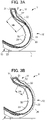
- FIG. 3A is a view schematically showing a partial cross section in the tire-width direction upon the tire 1 as the run-flat tire of the present embodiment making contact with the road surface H during zero internal pressure.
- FIG. 3B is a view schematically showing a partial cross section in the tire-width direction upon a run-flat tire 2 of side reinforcement type of a comparative example making contact with the road surface H during zero internal pressure.
- a road surface H side i.e. lower side in the paper plane, is a tire-radial direction outer side.
- the tire during zero internal pressure becomes a crushed state compared to the tire in FIG. 1 in a state filled with the standard internal pressure.
- during zero internal pressure indicates a state applying load of 65% of the weight corresponding to the load index, with the internal pressure of the tire being zero.
- the tire-radial direction length Hb overlap length Hb
- the tire-radial direction length Hb overlap length Hb
- the tire-radial direction length Ha is on the order of 50% of the tire-radial direction length Ha from the tire-radial direction outside end 22A of the bead filler 22 until the tire-radial direction inside end 22B, and sufficient length cannot be secured.
- stress concentration occurs in the vicinity of the bead 11 and the boundary region between the bead 11 and sidewall 12 during zero internal pressure, it greatly deforms in this portion as shown in FIG. 3B .
- the tire-radial direction length Hb (overlap length Hb) from the tire-radial direction outside end 22A of the bead filler 22 until the tire-radial direction inside end 50B of the reinforcement rubber layer 50 is at least 70% of the tire-radial direction length Ha from the tire-radial direction outside end 22A of the bead filler 22 until the tire-radial direction inside end 22B, and a variation range in total thickness obtained by summing thickness of the bead filler 22 and thickness of the reinforcement rubber layer 50, within a range from the tire radial-direction outside end 22A of the bead filler 22 to the tire radial-direction inside end 50B of the reinforcement rubber layer 50 is within 10%.
- the configuration of the present embodiment is particularly suitable in a run-flat tire for which the tire cross-sectional height H1 is large, as in a tire for SUVs.
- the tire cross-section height H1 being large, strong stress acts in the vicinity of the rim mounting part of the tire, and local deformation tends to occur.
- tire cross-sectional height H1 is the length in the tire-radial direction from the rim base line BL to the tire tread 13C of the tread 13, i.e. 1/2 of the difference between the outside diameter of the tire and the rim diameter.
- the configuration of the present embodiment is particularly suitable in the case of the tire radial-direction outside end 50A of the reinforcement rubber layer 50 extending to the region of the tread 13. More specifically, it is particularly suitable in the case of the tire radial-direction outside region of the reinforcement rubber layer 50 of crescent-moon shaped cross section being arranged on the inner side in the tire-radial direction of the tire width-direction outside end 26A of the steel belt.
- the rigidity in the vicinity of the shoulder which is the boundary region between the tread 13 and sidewall 12 is high. Therefore, strong stress acts in the vicinity of the rim mounting part of this part of the tire, and local deformation tends to occur. Even in such a case, so long as being the configuration of the present embodiment, it is possible to suppress local deformation from occurring in the vicinity of the rim mounting part, and thus run-flat durability can be improved.
- the tire of the present invention can be adopted as various types of tires such as of a car, light truck, truck or bus; however, it is particularly suitable as a tire for a car. Thereamong, the highest effect is obtained in a run-flat tire for SUVs having a large tire cross-sectional height. It should be noted that the present invention is not to be limited to the above-mentioned embodiment, and even if conducting modifications, improvements, etc. within a scope that can achieve the object of the present invention, will be encompassed in the scope of the present invention.
Landscapes
- Engineering & Computer Science (AREA)
- Mechanical Engineering (AREA)
- Tires In General (AREA)
Applications Claiming Priority (2)
| Application Number | Priority Date | Filing Date | Title |
|---|---|---|---|
| JP2019223434A JP7324133B2 (ja) | 2019-12-11 | 2019-12-11 | タイヤ |
| PCT/JP2020/042724 WO2021117424A1 (ja) | 2019-12-11 | 2020-11-17 | ランフラットタイヤ |
Publications (3)
| Publication Number | Publication Date |
|---|---|
| EP4074524A1 true EP4074524A1 (de) | 2022-10-19 |
| EP4074524A4 EP4074524A4 (de) | 2023-04-19 |
| EP4074524B1 EP4074524B1 (de) | 2024-08-07 |
Family
ID=76311535
Family Applications (1)
| Application Number | Title | Priority Date | Filing Date |
|---|---|---|---|
| EP20900369.8A Active EP4074524B1 (de) | 2019-12-11 | 2020-11-17 | Notlaufreifen |
Country Status (3)
| Country | Link |
|---|---|
| EP (1) | EP4074524B1 (de) |
| JP (1) | JP7324133B2 (de) |
| WO (1) | WO2021117424A1 (de) |
Family Cites Families (8)
| Publication number | Priority date | Publication date | Assignee | Title |
|---|---|---|---|---|
| JP2579398B2 (ja) * | 1991-12-05 | 1997-02-05 | 住友ゴム工業株式会社 | 空気入り安全タイヤ |
| US6719029B2 (en) * | 2002-08-09 | 2004-04-13 | The Goodyear Tire & Rubber Company | Tire wall gauges to optimize runflat tire ride comfort |
| JP6055587B2 (ja) | 2011-03-17 | 2016-12-27 | 株式会社ブリヂストン | 空気入りタイヤ |
| JP2013154819A (ja) * | 2012-01-31 | 2013-08-15 | Sumitomo Rubber Ind Ltd | ランフラットタイヤ |
| JP5921497B2 (ja) | 2013-07-10 | 2016-05-24 | 株式会社ブリヂストン | ランフラットタイヤ |
| JP6634833B2 (ja) * | 2016-01-07 | 2020-01-22 | 住友ゴム工業株式会社 | 空気入りタイヤ |
| JP6713112B2 (ja) * | 2016-04-27 | 2020-06-24 | 東京応化工業株式会社 | 化合物及びその製造方法 |
| JP6519623B2 (ja) * | 2017-10-02 | 2019-05-29 | 横浜ゴム株式会社 | ランフラットタイヤ |
-
2019
- 2019-12-11 JP JP2019223434A patent/JP7324133B2/ja active Active
-
2020
- 2020-11-17 EP EP20900369.8A patent/EP4074524B1/de active Active
- 2020-11-17 WO PCT/JP2020/042724 patent/WO2021117424A1/ja not_active Ceased
Also Published As
| Publication number | Publication date |
|---|---|
| JP7324133B2 (ja) | 2023-08-09 |
| WO2021117424A1 (ja) | 2021-06-17 |
| EP4074524A4 (de) | 2023-04-19 |
| JP2021091308A (ja) | 2021-06-17 |
| EP4074524B1 (de) | 2024-08-07 |
Similar Documents
| Publication | Publication Date | Title |
|---|---|---|
| CN110062705B (zh) | 泄气保用轮胎 | |
| EP3189987B1 (de) | Luftreifen | |
| EP3281805B1 (de) | Luftreifen | |
| EP3594019B1 (de) | Schwerlastluftreifen | |
| CN113825653B (zh) | 轮胎 | |
| EP3978275B1 (de) | Luftreifen | |
| EP4074524B1 (de) | Notlaufreifen | |
| EP3736142B1 (de) | Motorradreifen | |
| JP7238231B2 (ja) | 空気入りタイヤ | |
| JP7807910B2 (ja) | 空気入りタイヤ | |
| EP3189988B1 (de) | Luftreifen | |
| JP2021091294A (ja) | ランフラットタイヤ | |
| JP7836167B2 (ja) | 空気入りタイヤ | |
| JP7704519B2 (ja) | ランフラットタイヤ | |
| JP7798553B2 (ja) | 空気入りタイヤ | |
| JP7419047B2 (ja) | タイヤ | |
| JP7599923B2 (ja) | 空気入りタイヤ | |
| EP3967519A1 (de) | Notlaufreifen | |
| JP2019107950A (ja) | 重荷重用空気入りラジアルタイヤ | |
| JP2025102225A (ja) | 空気入りタイヤ | |
| JP2025102226A (ja) | 空気入りタイヤ | |
| JP2024083808A (ja) | 空気入りタイヤ | |
| JP2024014473A (ja) | 空気入りタイヤ | |
| JP2025177588A (ja) | 空気入りタイヤ | |
| JP2023093962A (ja) | 空気入りタイヤ |
Legal Events
| Date | Code | Title | Description |
|---|---|---|---|
| STAA | Information on the status of an ep patent application or granted ep patent |
Free format text: STATUS: THE INTERNATIONAL PUBLICATION HAS BEEN MADE |
|
| PUAI | Public reference made under article 153(3) epc to a published international application that has entered the european phase |
Free format text: ORIGINAL CODE: 0009012 |
|
| STAA | Information on the status of an ep patent application or granted ep patent |
Free format text: STATUS: REQUEST FOR EXAMINATION WAS MADE |
|
| 17P | Request for examination filed |
Effective date: 20220707 |
|
| AK | Designated contracting states |
Kind code of ref document: A1 Designated state(s): AL AT BE BG CH CY CZ DE DK EE ES FI FR GB GR HR HU IE IS IT LI LT LU LV MC MK MT NL NO PL PT RO RS SE SI SK SM TR |
|
| DAV | Request for validation of the european patent (deleted) | ||
| DAX | Request for extension of the european patent (deleted) | ||
| A4 | Supplementary search report drawn up and despatched |
Effective date: 20230322 |
|
| RIC1 | Information provided on ipc code assigned before grant |
Ipc: B60C 13/00 20060101ALI20230316BHEP Ipc: B60C 17/00 20060101ALI20230316BHEP Ipc: B60C 15/06 20060101AFI20230316BHEP |
|
| STAA | Information on the status of an ep patent application or granted ep patent |
Free format text: STATUS: EXAMINATION IS IN PROGRESS |
|
| 17Q | First examination report despatched |
Effective date: 20231002 |
|
| GRAP | Despatch of communication of intention to grant a patent |
Free format text: ORIGINAL CODE: EPIDOSNIGR1 |
|
| STAA | Information on the status of an ep patent application or granted ep patent |
Free format text: STATUS: GRANT OF PATENT IS INTENDED |
|
| INTG | Intention to grant announced |
Effective date: 20240318 |
|
| GRAS | Grant fee paid |
Free format text: ORIGINAL CODE: EPIDOSNIGR3 |
|
| GRAA | (expected) grant |
Free format text: ORIGINAL CODE: 0009210 |
|
| STAA | Information on the status of an ep patent application or granted ep patent |
Free format text: STATUS: THE PATENT HAS BEEN GRANTED |
|
| AK | Designated contracting states |
Kind code of ref document: B1 Designated state(s): AL AT BE BG CH CY CZ DE DK EE ES FI FR GB GR HR HU IE IS IT LI LT LU LV MC MK MT NL NO PL PT RO RS SE SI SK SM TR |
|
| REG | Reference to a national code |
Ref country code: GB Ref legal event code: FG4D |
|
| REG | Reference to a national code |
Ref country code: CH Ref legal event code: EP |
|
| REG | Reference to a national code |
Ref country code: IE Ref legal event code: FG4D |
|
| REG | Reference to a national code |
Ref country code: DE Ref legal event code: R096 Ref document number: 602020035548 Country of ref document: DE |
|
| REG | Reference to a national code |
Ref country code: LT Ref legal event code: MG9D |
|
| REG | Reference to a national code |
Ref country code: NL Ref legal event code: MP Effective date: 20240807 |
|
| PGFP | Annual fee paid to national office [announced via postgrant information from national office to epo] |
Ref country code: DE Payment date: 20241128 Year of fee payment: 5 |
|
| PG25 | Lapsed in a contracting state [announced via postgrant information from national office to epo] |
Ref country code: NO Free format text: LAPSE BECAUSE OF FAILURE TO SUBMIT A TRANSLATION OF THE DESCRIPTION OR TO PAY THE FEE WITHIN THE PRESCRIBED TIME-LIMIT Effective date: 20241107 |
|
| REG | Reference to a national code |
Ref country code: AT Ref legal event code: MK05 Ref document number: 1710555 Country of ref document: AT Kind code of ref document: T Effective date: 20240807 |
|
| PG25 | Lapsed in a contracting state [announced via postgrant information from national office to epo] |
Ref country code: NL Free format text: LAPSE BECAUSE OF FAILURE TO SUBMIT A TRANSLATION OF THE DESCRIPTION OR TO PAY THE FEE WITHIN THE PRESCRIBED TIME-LIMIT Effective date: 20240807 Ref country code: FI Free format text: LAPSE BECAUSE OF FAILURE TO SUBMIT A TRANSLATION OF THE DESCRIPTION OR TO PAY THE FEE WITHIN THE PRESCRIBED TIME-LIMIT Effective date: 20240807 Ref country code: PL Free format text: LAPSE BECAUSE OF FAILURE TO SUBMIT A TRANSLATION OF THE DESCRIPTION OR TO PAY THE FEE WITHIN THE PRESCRIBED TIME-LIMIT Effective date: 20240807 Ref country code: GR Free format text: LAPSE BECAUSE OF FAILURE TO SUBMIT A TRANSLATION OF THE DESCRIPTION OR TO PAY THE FEE WITHIN THE PRESCRIBED TIME-LIMIT Effective date: 20241108 Ref country code: PT Free format text: LAPSE BECAUSE OF FAILURE TO SUBMIT A TRANSLATION OF THE DESCRIPTION OR TO PAY THE FEE WITHIN THE PRESCRIBED TIME-LIMIT Effective date: 20241209 |
|
| PG25 | Lapsed in a contracting state [announced via postgrant information from national office to epo] |
Ref country code: BG Free format text: LAPSE BECAUSE OF FAILURE TO SUBMIT A TRANSLATION OF THE DESCRIPTION OR TO PAY THE FEE WITHIN THE PRESCRIBED TIME-LIMIT Effective date: 20240807 |
|
| PG25 | Lapsed in a contracting state [announced via postgrant information from national office to epo] |
Ref country code: LV Free format text: LAPSE BECAUSE OF FAILURE TO SUBMIT A TRANSLATION OF THE DESCRIPTION OR TO PAY THE FEE WITHIN THE PRESCRIBED TIME-LIMIT Effective date: 20240807 |
|
| PG25 | Lapsed in a contracting state [announced via postgrant information from national office to epo] |
Ref country code: IS Free format text: LAPSE BECAUSE OF FAILURE TO SUBMIT A TRANSLATION OF THE DESCRIPTION OR TO PAY THE FEE WITHIN THE PRESCRIBED TIME-LIMIT Effective date: 20241207 Ref country code: AT Free format text: LAPSE BECAUSE OF FAILURE TO SUBMIT A TRANSLATION OF THE DESCRIPTION OR TO PAY THE FEE WITHIN THE PRESCRIBED TIME-LIMIT Effective date: 20240807 |
|
| PG25 | Lapsed in a contracting state [announced via postgrant information from national office to epo] |
Ref country code: HR Free format text: LAPSE BECAUSE OF FAILURE TO SUBMIT A TRANSLATION OF THE DESCRIPTION OR TO PAY THE FEE WITHIN THE PRESCRIBED TIME-LIMIT Effective date: 20240807 |
|
| PG25 | Lapsed in a contracting state [announced via postgrant information from national office to epo] |
Ref country code: ES Free format text: LAPSE BECAUSE OF FAILURE TO SUBMIT A TRANSLATION OF THE DESCRIPTION OR TO PAY THE FEE WITHIN THE PRESCRIBED TIME-LIMIT Effective date: 20240807 Ref country code: RS Free format text: LAPSE BECAUSE OF FAILURE TO SUBMIT A TRANSLATION OF THE DESCRIPTION OR TO PAY THE FEE WITHIN THE PRESCRIBED TIME-LIMIT Effective date: 20241107 |
|
| PG25 | Lapsed in a contracting state [announced via postgrant information from national office to epo] |
Ref country code: RS Free format text: LAPSE BECAUSE OF FAILURE TO SUBMIT A TRANSLATION OF THE DESCRIPTION OR TO PAY THE FEE WITHIN THE PRESCRIBED TIME-LIMIT Effective date: 20241107 Ref country code: PT Free format text: LAPSE BECAUSE OF FAILURE TO SUBMIT A TRANSLATION OF THE DESCRIPTION OR TO PAY THE FEE WITHIN THE PRESCRIBED TIME-LIMIT Effective date: 20241209 Ref country code: PL Free format text: LAPSE BECAUSE OF FAILURE TO SUBMIT A TRANSLATION OF THE DESCRIPTION OR TO PAY THE FEE WITHIN THE PRESCRIBED TIME-LIMIT Effective date: 20240807 Ref country code: NO Free format text: LAPSE BECAUSE OF FAILURE TO SUBMIT A TRANSLATION OF THE DESCRIPTION OR TO PAY THE FEE WITHIN THE PRESCRIBED TIME-LIMIT Effective date: 20241107 Ref country code: NL Free format text: LAPSE BECAUSE OF FAILURE TO SUBMIT A TRANSLATION OF THE DESCRIPTION OR TO PAY THE FEE WITHIN THE PRESCRIBED TIME-LIMIT Effective date: 20240807 Ref country code: LV Free format text: LAPSE BECAUSE OF FAILURE TO SUBMIT A TRANSLATION OF THE DESCRIPTION OR TO PAY THE FEE WITHIN THE PRESCRIBED TIME-LIMIT Effective date: 20240807 Ref country code: IS Free format text: LAPSE BECAUSE OF FAILURE TO SUBMIT A TRANSLATION OF THE DESCRIPTION OR TO PAY THE FEE WITHIN THE PRESCRIBED TIME-LIMIT Effective date: 20241207 Ref country code: HR Free format text: LAPSE BECAUSE OF FAILURE TO SUBMIT A TRANSLATION OF THE DESCRIPTION OR TO PAY THE FEE WITHIN THE PRESCRIBED TIME-LIMIT Effective date: 20240807 Ref country code: GR Free format text: LAPSE BECAUSE OF FAILURE TO SUBMIT A TRANSLATION OF THE DESCRIPTION OR TO PAY THE FEE WITHIN THE PRESCRIBED TIME-LIMIT Effective date: 20241108 Ref country code: FI Free format text: LAPSE BECAUSE OF FAILURE TO SUBMIT A TRANSLATION OF THE DESCRIPTION OR TO PAY THE FEE WITHIN THE PRESCRIBED TIME-LIMIT Effective date: 20240807 Ref country code: ES Free format text: LAPSE BECAUSE OF FAILURE TO SUBMIT A TRANSLATION OF THE DESCRIPTION OR TO PAY THE FEE WITHIN THE PRESCRIBED TIME-LIMIT Effective date: 20240807 Ref country code: BG Free format text: LAPSE BECAUSE OF FAILURE TO SUBMIT A TRANSLATION OF THE DESCRIPTION OR TO PAY THE FEE WITHIN THE PRESCRIBED TIME-LIMIT Effective date: 20240807 Ref country code: AT Free format text: LAPSE BECAUSE OF FAILURE TO SUBMIT A TRANSLATION OF THE DESCRIPTION OR TO PAY THE FEE WITHIN THE PRESCRIBED TIME-LIMIT Effective date: 20240807 |
|
| PG25 | Lapsed in a contracting state [announced via postgrant information from national office to epo] |
Ref country code: DK Free format text: LAPSE BECAUSE OF FAILURE TO SUBMIT A TRANSLATION OF THE DESCRIPTION OR TO PAY THE FEE WITHIN THE PRESCRIBED TIME-LIMIT Effective date: 20240807 Ref country code: SM Free format text: LAPSE BECAUSE OF FAILURE TO SUBMIT A TRANSLATION OF THE DESCRIPTION OR TO PAY THE FEE WITHIN THE PRESCRIBED TIME-LIMIT Effective date: 20240807 |
|
| PG25 | Lapsed in a contracting state [announced via postgrant information from national office to epo] |
Ref country code: EE Free format text: LAPSE BECAUSE OF FAILURE TO SUBMIT A TRANSLATION OF THE DESCRIPTION OR TO PAY THE FEE WITHIN THE PRESCRIBED TIME-LIMIT Effective date: 20240807 |
|
| PG25 | Lapsed in a contracting state [announced via postgrant information from national office to epo] |
Ref country code: CZ Free format text: LAPSE BECAUSE OF FAILURE TO SUBMIT A TRANSLATION OF THE DESCRIPTION OR TO PAY THE FEE WITHIN THE PRESCRIBED TIME-LIMIT Effective date: 20240807 |
|
| PG25 | Lapsed in a contracting state [announced via postgrant information from national office to epo] |
Ref country code: SK Free format text: LAPSE BECAUSE OF FAILURE TO SUBMIT A TRANSLATION OF THE DESCRIPTION OR TO PAY THE FEE WITHIN THE PRESCRIBED TIME-LIMIT Effective date: 20240807 |
|
| REG | Reference to a national code |
Ref country code: DE Ref legal event code: R097 Ref document number: 602020035548 Country of ref document: DE |
|
| PLBE | No opposition filed within time limit |
Free format text: ORIGINAL CODE: 0009261 |
|
| STAA | Information on the status of an ep patent application or granted ep patent |
Free format text: STATUS: NO OPPOSITION FILED WITHIN TIME LIMIT |
|
| REG | Reference to a national code |
Ref country code: CH Ref legal event code: PL |
|
| PG25 | Lapsed in a contracting state [announced via postgrant information from national office to epo] |
Ref country code: MC Free format text: LAPSE BECAUSE OF FAILURE TO SUBMIT A TRANSLATION OF THE DESCRIPTION OR TO PAY THE FEE WITHIN THE PRESCRIBED TIME-LIMIT Effective date: 20240807 |
|
| PG25 | Lapsed in a contracting state [announced via postgrant information from national office to epo] |
Ref country code: LU Free format text: LAPSE BECAUSE OF NON-PAYMENT OF DUE FEES Effective date: 20241117 |
|
| REG | Reference to a national code |
Ref country code: CH Ref legal event code: PL |
|
| 26N | No opposition filed |
Effective date: 20250508 |
|
| GBPC | Gb: european patent ceased through non-payment of renewal fee |
Effective date: 20241117 |
|
| PG25 | Lapsed in a contracting state [announced via postgrant information from national office to epo] |
Ref country code: CH Free format text: LAPSE BECAUSE OF NON-PAYMENT OF DUE FEES Effective date: 20241130 |
|
| REG | Reference to a national code |
Ref country code: BE Ref legal event code: MM Effective date: 20241130 |
|
| PG25 | Lapsed in a contracting state [announced via postgrant information from national office to epo] |
Ref country code: SE Free format text: LAPSE BECAUSE OF FAILURE TO SUBMIT A TRANSLATION OF THE DESCRIPTION OR TO PAY THE FEE WITHIN THE PRESCRIBED TIME-LIMIT Effective date: 20240807 |
|
| PG25 | Lapsed in a contracting state [announced via postgrant information from national office to epo] |
Ref country code: BE Free format text: LAPSE BECAUSE OF NON-PAYMENT OF DUE FEES Effective date: 20241130 Ref country code: GB Free format text: LAPSE BECAUSE OF NON-PAYMENT OF DUE FEES Effective date: 20241117 |
|
| PG25 | Lapsed in a contracting state [announced via postgrant information from national office to epo] |
Ref country code: FR Free format text: LAPSE BECAUSE OF NON-PAYMENT OF DUE FEES Effective date: 20241130 |
|
| PG25 | Lapsed in a contracting state [announced via postgrant information from national office to epo] |
Ref country code: IE Free format text: LAPSE BECAUSE OF NON-PAYMENT OF DUE FEES Effective date: 20241117 |
|
| PG25 | Lapsed in a contracting state [announced via postgrant information from national office to epo] |
Ref country code: RO Free format text: LAPSE BECAUSE OF FAILURE TO SUBMIT A TRANSLATION OF THE DESCRIPTION OR TO PAY THE FEE WITHIN THE PRESCRIBED TIME-LIMIT Effective date: 20240807 |
|
| PG25 | Lapsed in a contracting state [announced via postgrant information from national office to epo] |
Ref country code: IT Free format text: LAPSE BECAUSE OF FAILURE TO SUBMIT A TRANSLATION OF THE DESCRIPTION OR TO PAY THE FEE WITHIN THE PRESCRIBED TIME-LIMIT Effective date: 20240807 |
|
| PG25 | Lapsed in a contracting state [announced via postgrant information from national office to epo] |
Ref country code: HU Free format text: LAPSE BECAUSE OF FAILURE TO SUBMIT A TRANSLATION OF THE DESCRIPTION OR TO PAY THE FEE WITHIN THE PRESCRIBED TIME-LIMIT; INVALID AB INITIO Effective date: 20201117 |
|
| PG25 | Lapsed in a contracting state [announced via postgrant information from national office to epo] |
Ref country code: CY Free format text: LAPSE BECAUSE OF FAILURE TO SUBMIT A TRANSLATION OF THE DESCRIPTION OR TO PAY THE FEE WITHIN THE PRESCRIBED TIME-LIMIT; INVALID AB INITIO Effective date: 20201117 |