EP4074546B1 - Verfahren zur montage einer rückblickvorrichtung und fahrzeug - Google Patents
Verfahren zur montage einer rückblickvorrichtung und fahrzeug Download PDFInfo
- Publication number
- EP4074546B1 EP4074546B1 EP22163894.3A EP22163894A EP4074546B1 EP 4074546 B1 EP4074546 B1 EP 4074546B1 EP 22163894 A EP22163894 A EP 22163894A EP 4074546 B1 EP4074546 B1 EP 4074546B1
- Authority
- EP
- European Patent Office
- Prior art keywords
- door
- attachment portion
- harness
- assembly
- opening
- Prior art date
- Legal status (The legal status is an assumption and is not a legal conclusion. Google has not performed a legal analysis and makes no representation as to the accuracy of the status listed.)
- Active
Links
Images




Classifications
-
- B—PERFORMING OPERATIONS; TRANSPORTING
- B60—VEHICLES IN GENERAL
- B60R—VEHICLES, VEHICLE FITTINGS, OR VEHICLE PARTS, NOT OTHERWISE PROVIDED FOR
- B60R1/00—Optical viewing arrangements; Real-time viewing arrangements for drivers or passengers using optical image capturing systems, e.g. cameras or video systems specially adapted for use in or on vehicles
- B60R1/02—Rear-view mirror arrangements
- B60R1/06—Rear-view mirror arrangements mounted on vehicle exterior
-
- B—PERFORMING OPERATIONS; TRANSPORTING
- B60—VEHICLES IN GENERAL
- B60R—VEHICLES, VEHICLE FITTINGS, OR VEHICLE PARTS, NOT OTHERWISE PROVIDED FOR
- B60R1/00—Optical viewing arrangements; Real-time viewing arrangements for drivers or passengers using optical image capturing systems, e.g. cameras or video systems specially adapted for use in or on vehicles
- B60R1/02—Rear-view mirror arrangements
- B60R1/06—Rear-view mirror arrangements mounted on vehicle exterior
- B60R1/062—Rear-view mirror arrangements mounted on vehicle exterior with remote control for adjusting position
- B60R1/064—Rear-view mirror arrangements mounted on vehicle exterior with remote control for adjusting position by manually powered actuators
- B60R1/066—Rear-view mirror arrangements mounted on vehicle exterior with remote control for adjusting position by manually powered actuators for adjusting the mirror relative to its housing
-
- B—PERFORMING OPERATIONS; TRANSPORTING
- B60—VEHICLES IN GENERAL
- B60R—VEHICLES, VEHICLE FITTINGS, OR VEHICLE PARTS, NOT OTHERWISE PROVIDED FOR
- B60R1/00—Optical viewing arrangements; Real-time viewing arrangements for drivers or passengers using optical image capturing systems, e.g. cameras or video systems specially adapted for use in or on vehicles
- B60R1/02—Rear-view mirror arrangements
- B60R1/06—Rear-view mirror arrangements mounted on vehicle exterior
- B60R1/062—Rear-view mirror arrangements mounted on vehicle exterior with remote control for adjusting position
- B60R1/07—Rear-view mirror arrangements mounted on vehicle exterior with remote control for adjusting position by electrically powered actuators
- B60R1/072—Rear-view mirror arrangements mounted on vehicle exterior with remote control for adjusting position by electrically powered actuators for adjusting the mirror relative to its housing
-
- B—PERFORMING OPERATIONS; TRANSPORTING
- B60—VEHICLES IN GENERAL
- B60R—VEHICLES, VEHICLE FITTINGS, OR VEHICLE PARTS, NOT OTHERWISE PROVIDED FOR
- B60R1/00—Optical viewing arrangements; Real-time viewing arrangements for drivers or passengers using optical image capturing systems, e.g. cameras or video systems specially adapted for use in or on vehicles
- B60R1/12—Mirror assemblies combined with other articles, e.g. clocks
-
- B—PERFORMING OPERATIONS; TRANSPORTING
- B60—VEHICLES IN GENERAL
- B60R—VEHICLES, VEHICLE FITTINGS, OR VEHICLE PARTS, NOT OTHERWISE PROVIDED FOR
- B60R11/00—Arrangements for holding or mounting articles, not otherwise provided for
- B60R11/04—Mounting of cameras operative during drive; Arrangement of controls thereof relative to the vehicle
-
- B—PERFORMING OPERATIONS; TRANSPORTING
- B60—VEHICLES IN GENERAL
- B60R—VEHICLES, VEHICLE FITTINGS, OR VEHICLE PARTS, NOT OTHERWISE PROVIDED FOR
- B60R1/00—Optical viewing arrangements; Real-time viewing arrangements for drivers or passengers using optical image capturing systems, e.g. cameras or video systems specially adapted for use in or on vehicles
- B60R1/12—Mirror assemblies combined with other articles, e.g. clocks
- B60R2001/1253—Mirror assemblies combined with other articles, e.g. clocks with cameras, video cameras or video screens
-
- B—PERFORMING OPERATIONS; TRANSPORTING
- B60—VEHICLES IN GENERAL
- B60R—VEHICLES, VEHICLE FITTINGS, OR VEHICLE PARTS, NOT OTHERWISE PROVIDED FOR
- B60R11/00—Arrangements for holding or mounting articles, not otherwise provided for
- B60R2011/0001—Arrangements for holding or mounting articles, not otherwise provided for characterised by position
- B60R2011/004—Arrangements for holding or mounting articles, not otherwise provided for characterised by position outside the vehicle
-
- B—PERFORMING OPERATIONS; TRANSPORTING
- B60—VEHICLES IN GENERAL
- B60R—VEHICLES, VEHICLE FITTINGS, OR VEHICLE PARTS, NOT OTHERWISE PROVIDED FOR
- B60R2300/00—Details of viewing arrangements using cameras and displays, specially adapted for use in a vehicle
- B60R2300/10—Details of viewing arrangements using cameras and displays, specially adapted for use in a vehicle characterised by the type of camera system used
-
- B—PERFORMING OPERATIONS; TRANSPORTING
- B60—VEHICLES IN GENERAL
- B60R—VEHICLES, VEHICLE FITTINGS, OR VEHICLE PARTS, NOT OTHERWISE PROVIDED FOR
- B60R2300/00—Details of viewing arrangements using cameras and displays, specially adapted for use in a vehicle
- B60R2300/80—Details of viewing arrangements using cameras and displays, specially adapted for use in a vehicle characterised by the intended use of the viewing arrangement
- B60R2300/8046—Details of viewing arrangements using cameras and displays, specially adapted for use in a vehicle characterised by the intended use of the viewing arrangement for replacing a rear-view mirror system
Definitions
- the present invention refers to a method for assembling a rear view device with a retainer assembly adapted to be installed between a base assembly of the rear view device and a vehicle, and to a vehicle with such an assembled rear view device.
- a rear view device typically includes a base assembly to be attached to a vehicle and a head assembly to be moveable relative to the base assembly.
- the head assembly of a rear view device can be rotated between a driving position and a parking position.
- the term "rear view” may refer to a view of the surrounding area, which is not in the field of view of a driver of a vehicle, i.e. the directions opposing, left, right, below and above of the viewing direction, but can also comprise the view in the direction of the viewing direction of the driver and/or any combinations of the directions.
- the rear view can be achieved via at least one rear view element in form of a reflective element like a mirror and/or an image acquisition means like a camera.
- the rear view, that is the field of view of the driver can be adjusted by moving, in particular rotating, the reflective element and/or the image acquisition means. This in turn can be realized by moving the complete head assembly together with the reflective element and/or the image acquisition means such that the head assembly of the rear view device can be rotated also between a plurality of viewing position.
- an actuator assembly is comprised by the rear view device, which can be controlled by a first control unit within the vehicle. Also the image acquisition means can be controlled via a second control unit, wherein both control units may be formed together. However, for the purpose of controlling data have to be transferred between the rear view device and the control unit within the vehicle requiring a harness.
- US 6,039,449 A describes a rear view mirror, including a temporary hold-down clip for holding said mirror to a vehicle body panel during vehicle assembly, comprising: a mirror housing with a mirror affixed thereto; a plurality of fastening studs secured to said housing and projecting therefrom in a direction of attachment to said vehicle body panel; a sleeve having an aperture, said sleeve projecting from said housing in the direction of attachment of said studs; and a set of elongate snap-fit fingers located around an outer periphery of said sleeve, said fingers including shanks projecting outwardly from said housing in said direction of attachment whereby said rear view mirror is temporarily held to said vehicle body by said snap-fit fingers inserted into said body panel, said body panel being a portion of said vehicle body.
- WO 2014/002797 A1 teaches a door mirror having a door mirror main body attached to a door mirror mounting portion of a vehicle body, comprising: a shared base fixed to the door mirror mounting portion to support the shared door mirror main body; a door mirror, comprising: a dedicated cover selected from a plurality of types of dedicated cover groups and covering a peripheral area of a door mirror mounting portion.
- US 4,973,147 A refers to a holding device for a connector associated with an electrically controlled automotive mirror, the connector being adapted for connection to a mated connector provided in an automotive vehicle body, the device comprising: a mirror unit, adapted for connection to an automotive vehicle body, including a mirror, an electrical driving device for driving the mirror, and a housing for housing the mirror and the electrical driving device; a bracket adapted to be fixed to a side of the housing adapted for connection to the automotive vehicle body; a through hole provided in the bracket, the through hole including two engaging portions at opposing sides of the through hole; a hollow cylindrical member including a non-elastic claw and an elastic claw, the non-elastic claw being adapted to engage with one of the engaging portions, the elastic claw being adapted to engage with another one of the engaging portions; and a connector provided at an end of a wiring extending from the electrical driving device, the connector being adapted for insertion into and to be held by an inner surface of the hollow cylindrical member.
- GB 2 396 881 A teaches a vehicle door comprising a main glazed panel, a quarter glass and a window frame which includes a divider bar which in use extends substantially vertically between the quarter glass and the main glazed panel and a base member which in use extends substantially horizontally below the quarter glass and formed integrally with the divider bar, the quarter glass being fixed to the integral divider bar and base member.
- US 2020/0001791 A1 refers to a base assembly of an exterior rear view device, comprising a base frame; and a base cover housing the base frame and formed in at least two parts connected to each other, wherein the base assembly comprises a first opening at a first end of the base assembly at which the base frame is configured to be attached to a vehicle and a second opening at a second end of the base assembly at which a head assembly of the exterior rear view device is configured to be attached to the base frame, wherein at least one of a first sealing means at the first opening is provided comprising a two-component gasket with a hard component and a soft component, the hard component comprising: at least one first connection element configured to engage at least one first connection element of a first cover part; and at least one first connection element of a second cover part configured to provide a locking connection between the first cover part and the second cover part, and/or a second sealing means at the second opening
- the base frame fulfills a multitude of functions, in particular that of supporting the head assembly and connecting the same as well as electronic components of the exterior rear view device to the vehicle and a central control unit within the vehicle, the latter requiring a harness to be safely guided and sealed, electrically as well as with respect to moisture.
- the base frame is made of metal, often aluminum, fulfilling said functions is a challenge.
- the retainer assembly is to assist in fulfilling the tasks of guiding and sealing a harness on its path from the interior of the vehicle into the exterior rear view device attached to the vehicle.
- a retainer assembly is adapted to be installed between a base assembly of an exterior rear view device and a vehicle to which the exterior rear view device is mounted, the retainer assembly comprising a retainer means adapted to be mounted on one side to a door attachment portion of a base frame of the base assembly and on the opposite side to a door panel of the vehicle, wherein the retainer means is provided with at least one opening for allowing at least one datum structural element of the door attachment portion of the base frame to pass thereto, and at least one guiding projection and/or at least one guiding channel portion for providing at least part of a guiding channel for routing and/or guiding at least one harness from the vehicle to an electric component of the rear view device, and/or at least one sealing portion for covering at least a portion of the at least one harness.
- the at least one opening is provided by a holding portion, with preferably a first opening allowing a location pin of the door attachment portion to pass thereto, and/or at least one second opening allowing a T shaped location projection of the door attachment portion to pass thereto.
- At least one first hook and/or first clip is provided by the holding portion for attachment to the door panel, and/or at least one second hook and/or second clip is provided by the holding portion for attachment to the door attachment portion, with preferably the first and second hook(s) and/or clips(s) extending in opposite directions.
- the first hook is adapted to hold the rear view device in Y direction to assist an assembly thereof to the door panel, preferably via screws, and/or the first clip determines the final assembly Z position of the rear view device, and/or the first clip is arranged next to the first opening, and/or the first hook provides the at least one second opening, and/or there are at least two second clips.
- the retainer means may be provided with at least one datum area and/or with at least one T shaped location projection within a datum area for a base cover.
- the retainer means may form a single component, preferably from plastic.
- the retainer assembly further comprises a sealing means adapted to be mounted on the retainer means, preferably by being attached to the retainer means via at least one snap and/or chip connection and/or to the door attachment portion, in particular via at least one screw, clips and/or snap connection.
- the sealing means may be in form of a 2K door gasket and/or may be provided with at least one datum area for a base cover.
- an exterior rear view device with a base assembly for attachment to a vehicle, a head assembly with at least one reflective element and/or image acquisition means, with the head assembly being moveable relative to the base assembly, and the retainer assembly, wherein the sub-assembly of the base frame, the sealing means and the retainer means forms a channel for positioning a glass run seal, in particular allocated to a cheater panel.
- the base frame is provided at a first end with the door attachment portion and at a second end with a head attachment portion, with the major portion between theses ends being provided in form of an arm, wherein preferably the door attachment portion extends substantially perpendicularly to the arm.
- the door attachment portion is provided with an opening for a harness holder, wherein preferably the harness holder is provided with a fixing tie for holding the harness and a cli for engaging said opening such that the harness is firmly located to the base frame in all directions.
- a camera harness is comprised by the harness, with the camera harness preferably splitting off the harness adapted for routing and/or between the harness holder and the retainer means.
- the at least one guiding projection and/ or guiding channel is guiding the camera harness, and/or the sealing portion is covering the camera harness, in particular in a bending region between the door attachment portion and the arm of the base frame.
- the electric component comprises at least one camera, wherein preferably the camera is arranged in the base assembly.
- the base cover comprises a base cover cap and an upper base cover, wherein preferably the base cover cap and an upper base cover are attached via snap and/or clip connections, and/or the head assembly comprises a lower case with an opening dimensioned such that the base frame with its arm and door attachment portion together with the retainer means can pass.
- the method for assembling the rear view device comprises the following steps: clamping the retaining means on the door attachment portion of the base frame, guiding the door attachment portion with the attached retaining means through the opening of the lower case of the head assembly, and clamping the sealing means onto the door attachment portion and/or the retaining means, which preferably the sealing means and the retaining means being screwed onto the door attachment portion.
- the following steps may also be comprised: attaching the harness to the door attachment portion via the harness holder, preferably prior to the clamping of the retaining means on the door attachment portion of the base frame.
- the following steps may be comprised: passing the hook of the door attachment portion through a first opening in the door panel to obtain a hang connection, entering screws into the screw openings of the door panel and into the screw openings of the door attachment portion, and passing the positioning pin of the door attachment portion through a second opening in the door panel and clamping the clip of the retainer means to the door panel by passing through said second opening.
- the T shaped location projection of the door attachment portion engages the door panel by passing with its arms through openings provided by the hook, and/or the clip is arranged between the positioning pin and the hook, and/or the clip and the positioning pin engage opposite regions of the second opening of the door panel.
- the sub-assembly of the base frame, the sealing means and the retainer means forms a channel, and the cheater panel pushes the glass run seal at least partly into the channel.
- the base cover cap and the upper base cover are assembled by rotating into clip connecting, and/or the gap between the base cover cap and the upper base cover on the one side and the door on the other side is sealed by the glass run seal being pushed against and/or into the channel as well as the cheater panel during the assembling the base cover cap and the upper base cover.
- the present disclosure also provides according to a still further aspect a vehicle with the rear view device assembled according to the method of the present disclosure such that the base assembly merges out of the glass run seal and/or a door waist finisher.
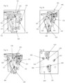
- Figures 1a to 2d show a retainer means 301 of a retainer assembly 300 to be arranged between a base frame 110 of a base assembly 100 of an exterior rear view device 1 and a door panel 605 of a door 600 of a vehicle 2.
- the retainer means 301 may be manufactured from a plastic material, whereas the base frame 110 is metallic and may be manufactured from aluminum.
- the figures 1a to 1c also show a harness 400 for electrically connecting in particular a power source and a control unit within the vehicle (not shown) with electric components of the exterior rear view device.
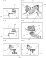
- electric components may comprise, as e.g. shown in figures 3a to 3g , an actuator assembly 210 suitable for moving a head assembly 200 together with a reflective element (not shown) relative to the base frame 110 supporting the head assembly 200, and a camera 700 as well as an indicator means like a turn signal indicator 710 shown in figure 7 .
- Said harness 400 may comprise a camera harness 410.
- the retainer means 301 is a multi-function component. The different functions will be described with respect to the other components of the exterior rear view device 1 as well as the vehicle 2 in the following.
- the base frame 110 has a door attachment portion 115 at one end, with said door attachment portion 115 being provided with an opening 124 for a harness holder 500 at its lower, free end, as best seen in figures 1d and 1e .
- Said harness holder 500 is formed with a fixing tie 510 for holding the harness 400 and a clip 520 for connecting the holder 500 to said door attachment portion 115 by passing through the opening 124.
- the base frame harness locator opening feature governs harness position length the door side and the rear view device side, and provides a strong retention eliminating risk of the harness 400 being misplaced e.g. by being pulled through during handling. Further, the locating feature leads to reduced tolerance of fit-to-door.
- the harness 400 is firmly located to the base frame 110 in all directions allowing a solid datum strategy for harness lengths and provides the ability to hold as well as transport the exterior rear view device 1 whilst holding on to the harness 400.
- the harness 400 as well as the camera harness 410 divided therefrom above the harness holder 500 extend between the door attachment portion 115 of the base frame 110 and a holding portion 320 of the retainer means 301 to an upper end of the door attachment portion 115, which turns into a main portion of the base frame 110 extending away from the door panel 605 towards the head assembly 200, being provided in form of an arm 116, with a head assembly attachment portion 117 of the base frame 110 being provided at the second end of the base frame 110 opposite the first end, see e.g. figure 3a .
- the retainer means 301 is provided with a guiding projection 122 for guiding the camera harness 410 to a sealing portion 310 of the retainer means 301 extending substantially perpendicularly to the holding portion 320 to cover the camera harness 410 at its bending region at the transition between the door attachment portion 115 and the arm 116.
- the holding portion 320 of the retainer means 301 also provides a camera harness guiding channel portion 340 to substantially close a channel 420 for the camera harness 410, as shown in figure 1c .
- the sealing of the harness 400, together with the camera harness 410, as well as the attachment of the metallic base frame 110 to the door panel 605 becomes safer.
- the design of the retainer means 301 allows to accommodate different sets of harness and cleaning system for all variations of mirror trim level.
- the retainer means 301 ensures an easy assembly to seal in particular the camera harness 410 after being mounted and to manage its routing along the base frame door attachment portion 115, without departing from the commonly used datum system between the base frame 110 and the door panel 605, further illustrated in the following:
- the base frame 110 is provided with a location pin 120 as well as a T shaped location projection 121 belonging to the datum system ensuring a correct assembly of the components of the exterior rear view device 1 and a correct attachment of the exterior rear view device 1 to the vehicle 2.
- the location pin 120 and the T shaped location projection 121 extend substantially perpendicularly to the plane of the door panel 605, as can be best seen in figures 2a and 2d .
- the retainer means 301 is provided with an opening 322 for the location pin 120 and a hook 350 with openings 351 for the arms of T shaped location projection 121, as can be best seen in figure 2b.
- Figure 2d illustrates that the location pin 120 as well as the T shaped location projection 121 pass through the respective openings 322, 351 of the retainer means 301 to also pass respective openings 610, 620 within the door panel 605 to engage the same, with the hook 350 of the retainer means 301 ensuring the respective engagement.
- the base frame T shaped location projection 121 and the location pin 120 provide the primary and secondary datum strategy to the door datum system in X + Z directions, while the Y direction is controlled using three screw bosses.
- the door panel 605 in figure 2d shows two screw openings 631 and 632 aligned to two screw openings 131 and 132 of the base frame 110, respectively, which in turn pass openings 371 and 372 of the retainer means 301.
- the corresponding locating features of the base frame 110 and the retainer means 301 allow base frame datum features to interface with the door 600 minimizing tolerance of datum strategy.
- the retainer means 301 along with the location pin 120 and the T shaped location projection 121 not only provides an accurate assembly to the door panel datum system, but also facilitates the assembly as it provides a robust 3rd hand clip/hanger function, as further illustrated in the following:
- the retainer means 301 provides attachment features to support assembly to the base frame 110 as well as the door, by being formed with the hook 350 and clips 315, 316, 360.
- Two clips 315 and 316 serve the attachment to the base frame 110 as best seen in figures 1a, 1b and 5b .
- the hook 350 primarily serves to hold the exterior rear view device 1 in Y direction to assist assembly of the screws (not shown), while the third clip 360 is on secondary location keyway to highlight when the exterior rear view device 1 is in its final assembly Z position, as best seen in figure 2d .
- the retainer assembly 300 comprises, in addition to the retainer means 301, a sealing means 800 in form of a 2K door gasket.
- a sealing means 800 in form of a 2K door gasket.
- the sealing means 800 is mounted after the lower case 220, as shown in figures 3f and 3g .
- the sealing means location strategy is critical as it dictates the datum strategy for the corresponding base cover components discussed with respect to figures 6a to 6g below.
- the smaller base frame geometry and the provision of a separate 2K door gasket provided by the sealing means 800 permit the lower case 220 to be assembled over the base frame 110, and a T section support structure for the base cover permits a simple clip together assembly.
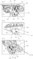
- sealing means 800 In to following the attachment of the sealing means 800 is described with reference to figures 5a to 5c : Four clips 810, 820, 830 and 840 allow to attach the sealing means 800 to the base frame 110, with the base frame 110 comprising complementary steps 135 and 136 as well as openings 137 and 138.
- the two screw positions determined by the openings 881, 882 allow to secure the sealing means 800 and retainer means 301 to the base frame 110. These are package protections only if more strength is required.
- the sub-assembly of the base frame 110, the retainer means 301 and the sealing means 800 forms a channel 900, see figures 6a and 6b , for positioning / locating a glass run seal 920 in particular allocated to a cheater panel 640 as shown e.g. in figure 6c .
- a base cover cap 150 and a base cover upper or upper base cover 180 are described with reference to figures 6c to 6f :
- the combination the base frame 110, the retainer means 301 and the sealing means 800 forms the channel 900 which locates the glass run seal 920 on to the exterior rear view device 1.
- the glass run seal 920 runs along the cheater panel 640 and is an extension of the glass run seal running along the window 1000 and being covered by a door trim 940 as shown in figures 6d and 7 .
- the base cover cap 180 clips to the base frame 110, see figure 6d , and also the upper base cover 190 is attached by clip connection, see Figure 6e .
- the clip connection may be located behind a chrome wait finisher (not shown).
- the cheater panel 640 pushes the glass run seal 920 into the correct position inside the channel 900 while being assembled.
- the base cover cap 180 and the upper base cover 190 assemble in such a way that when rotating into their position a sealing lip of the glass run seal 920 is pushed against the cheater panel 640 sealing the gap between the base cover cap 180 and the upper base cover 190 on the one side and the cheater panel 640 on the other side, see figure 6f .
- the exterior rear view device 1 holds the glass run seal 920 in a solid position as shown in figure 6f .
- This provides a very pleasing overall appearance suggesting that the exterior rear view device 1 extends or rather grows out of a wait finisher 940 covering a part of the glass run seal 920, see figure 7 .
Landscapes
- Engineering & Computer Science (AREA)
- Mechanical Engineering (AREA)
- Multimedia (AREA)
- Seal Device For Vehicle (AREA)
- Rear-View Mirror Devices That Are Mounted On The Exterior Of The Vehicle (AREA)
- Automobile Manufacture Line, Endless Track Vehicle, Trailer (AREA)
- Fittings On The Vehicle Exterior For Carrying Loads, And Devices For Holding Or Mounting Articles (AREA)
Claims (18)
- Verfahren zur Montage einer Außenrückblickvorrichtung (1) mit einer Basisbaugruppe (100) zur Anbringung an einem Fahrzeug (2), einer Kopfbaugruppe (200) mit wenigstens einem reflektierenden Element und/oder Bilderfassungsmittel, wobei die Kopfbaugruppe (200) relativ zur Basisbaugruppe (100) bewegbar ist, und einer Rückhaltebaugruppe (300), wobeidie Rückhaltebaugruppe (300) dazu angepasst ist, zwischen der Basisbaugruppe (100) der Außenrückblickvorrichtung (1) und dem Fahrzeug (2), an dem die Außenrückblickvorrichtung (1) montiert ist, installiert zu sein, wobei die Rückhaltebaugruppe (300) ein Rückhaltemittel (301) umfasst, das dazu angepasst ist, auf einer Seite an einem Türanbringungsabschnitt (115) eines Basisrahmens (110) der Basisbaugruppe (100) und auf der gegenüberliegenden Seite an einem Türblatt (605) des Fahrzeugs (2) montiert zu sein, wobei das Rückhaltemittel (301) bereitgestellt ist mit:• wenigstens einer Öffnung (322, 351), die es wenigstens einem Bezugsstrukturelement des Türanbringungsabschnitts (115) des Basisrahmens (110) ermöglicht, dort hindurch zulaufen, und• wenigstens einem Führungsvorsprung und/oder wenigstens einem Führungskanalabschnitt (340) zum Bereitstellen wenigstens eines Teils eines Führungskanals (420) zum Verlegen und/oder Führen wenigstens eines Kabelstrangs (400, 410) von dem Fahrzeug zu einer elektrischen Komponente (210, 700, 710) der Rückblickvorrichtung (1), und/oder• wenigstens einem Abdichtabschnitt (310) zum Abdecken wenigstens eines Teils des wenigstens einen Kabelstrangs (400, 410); undein Abdichtmittel (800) dazu angepasst ist, an dem Rückhaltemittel (301) montiert zu sein,die Unterbaugruppe des Basisrahmens (110), das Abdichtmittel (800) und das Rückhaltemittel (301) einen Kanal (900) zum Positionieren einer Glaslaufdichtung (920), insbesondere einer Dreieckblende (640) zugeordnet, ausbilden,wobei das Verfahren die folgenden Schritte umfasst:• Befestigen des Rückhaltemittels (301) am Türanbringungsabschnitt (115) des Basisrahmens (110),• Führen des Türanbringungsabschnitts (115) mit dem angebrachten Rückhaltemittel (301) durch die Öffnung (222) des unteren Gehäuses (220) der Kopfbaugruppe (200), und• Befestigen des Abdichtmittels (800) an dem Türanbringungsabschnitt (115) und/oder dem Rückhaltemittel (301), wobei das Abdichtmittel (800) und das Rückhaltemittel (301) gemeinsam an den Türanbringungsabschnitt (119) geschraubt sind.
- Verfahren nach Anspruch 1, ferner umfassend den folgenden Schritt:• Bereitstellen der wenigstens einen Öffnung (322, 351) durch einen Halteabschnitt (320) des Rückhaltemittels (301), wobei vorzugsweise• eine erste Öffnung (322) es einem Positionierungsstift (120) des Türanbringungsabschnitts (115) ermöglicht, dort hindurch zulaufen, und/oder• wenigstens eine zweite Öffnung (351) es einem T-förmigen Positionierungsvorsprung (121) des Türanbringungsabschnitts (115) ermöglicht, dort hindurch zulaufen.
- Verfahren nach Anspruch 1 oder 2, ferner umfassend den/die folgende/n Schritt/e:• Bereitstellen wenigstens eines ersten Hakens (350) und/oder einer ersten Klammer (360) durch den Halteabschnitt (320) zum Anbringen an dem Türblatt (605), und/oder• Bereitstellen wenigstens eines zweiten Hakens und/oder einer zweiten Klammer (315, 316) durch den Halteabschnitt (320) zum Anbringen an dem Türanbringungsabschnitt (115),wobei sich der erste und zweite Haken und/oder die erste und zweite Klammer vorzugsweise in entgegengesetzten Richtungen erstrecken.
- Verfahren nach Anspruch 3, ferner umfassend den/die folgende/n Schritt/e:• Anpassen des ersten Hakens (350), um die Rückblickvorrichtung (1) in Y-Richtung zu halten, um deren Montage an dem Türblatt (605), vorzugsweise mittels Schrauben, zu unterstützen, und/oder Festlegen der finalen Z-Montageposition der Rückblickvorrichtung (1) durch die erste Klammer (360), und/oder• Anordnen der ersten Klammer (360) neben der ersten Öffnung (322), und/oder• Bereitstellen der wenigstens einen zweiten Öffnung (351) durch den ersten Haken (360) und/oder Bereitstellen von wenigstens zwei zweiten Klammern (315, 316).
- Verfahren nach einem der vorangehenden Ansprüche, ferner umfassend den folgenden Schritt: Versehen des Rückhaltemittels (301) mit wenigstens einem Bezugsbereich und/oder mit wenigstens einem T-förmigen Positionierungsvorsprung (390) innerhalb eines Bezugsbereichs für eine Basisabdeckung.
- Verfahren nach einem der vorangehenden Ansprüche, ferner umfassend den/die folgenden Schritt/e: Anbringen des Abdichtmittels (800) an dem Rückhaltemittel (301) über wenigstens eine Schnapp- und/oder Klammerverbindung und/oder an dem Türanbringungsabschnitt (115), insbesondere über wenigstens eine Schraube, Klammern und/oder eine Schnappverbindung,
wobei das Abdichtmittel (800) vorzugsweise mit wenigstens einem Bezugsbereich (850) für eine Basisabdeckung versehen ist. - Verfahren nach einem der vorangehenden Ansprüche, ferner umfassend den folgenden Schritt:• Ausbilden des Rückhaltemittels (301) als eine einzelne Komponente, vorzugsweise aus Kunststoff, und/oder• Bereitstellen des Abdichtmittels (800) in Form einer 2K-Türabdichtung.
- Verfahren nach einem der vorangehenden Ansprüche, ferner umfassend den folgenden Schritt: Versehen des Basisrahmens (110) an einem ersten Ende mit dem Türanbringungsabschnitt (115) und an einem zweiten Ende mit einem Kopfanbringungsabschnitt (117), wobei der Hauptabschnitt zwischen diesen Enden in Form eines Arms (116) bereitgestellt ist,
wobei sich der Türanbringungsabschnitt (115) vorzugsweise im Wesentlichen senkrecht zum Arm (116) erstreckt. - Verfahren nach einem der vorangehenden Ansprüche, ferner umfassend den folgenden Schritt: Versehen des Türanbringungsabschnitts (115) mit einer Öffnung (124) für einen Kabelbaumhalter (500),
wobei der Kabelstranghalter (500) vorzugsweise mit einem Befestigungsband (510) zum Halten des Kabelstrangs (400) und einer Klammer (520) zum Eingreifen in die Öffnung (124) versehen ist, so dass der Kabelstrang (400) in allen Richtungen fest an dem Basisrahmen (110) angebracht ist. - Verfahren nach Anspruch 9, ferner umfassend den folgenden Schritt:• Umfassen eines Kamerakabelstrangs (410) durch den Kabelstrang (400), wobei der Kamerakabelstrang (410) vorzugsweise den Kabelstrang (400) zwischen dem Kabelstranghalter (500) und dem Rückhaltemittel (301) trennt, und/oder• Verlegen und/oder Führen des Kamerakabelstrangs (410) durch den wenigstens einen Führungsvorsprung und/oder Führungskanal (420), und/oder• Abdecken des Kamerakabelstrangs (410) durch den Abdichtabschnitt (310), insbesondere in einem Krümmungsbereich zwischen dem Türanbringungsabschnitt (115) und dem Arm (116) des Basisrahmens (110).
- Verfahren nach einem der vorangehenden Ansprüche, ferner umfassend den folgenden Schritt:
Anordnen wenigstens einer in der elektrischen Komponente umfassten Kamera (700) in der Basisbaugruppe (100). - Verfahren nach einem der vorangehenden Ansprüche, ferner umfassend den folgenden Schritt:• Bereitstellen einer Basisabdeckkappe (180) und einer oberen Basisabdeckung (190), indem sie in der Basisabdeckung umfasst sind,
wobei die Basisabdeckkappe (180) und eine obere Basisabdeckung (190) vorzugsweise über Schnapp- und/oder Klammerverbindungen angebracht sind, und/oder• Bereitstellen eines durch die Kopfbaugruppe (200) umfassten unteren Gehäuses (220) mit einer Öffnung (222), wobei die Öffnung (222) so dimensioniert ist, dass der Basisrahmen (110) mit seinem Arm (116) und der Türanbringungsabschnitt (115) gemeinsam mit dem Rückhaltemittel (301) hindurchverlaufen können. - Verfahren nach einem der vorangehenden Ansprüche, ferner umfassend den folgenden Schritt: Anbringen des Kabelstrangs (400) über den Kabelstranghalter (500) an den Türanbringungsabschnitt (115), vorzugsweise vor dem Befestigen des Rückhaltemittels (301) am Türanbringungsabschnitt (115) des Basisrahmens (110).
- Verfahren nach einem der vorangehenden Ansprüche, ferner umfassend die folgenden Schritte:• Führen des Hakens (350) des Türanbringungsabschnitts (115) durch eine erste Öffnung (610) im Türblatt (605), um eine Hängeverbindung zu erhalten,• Einsetzen von Schrauben in die Schraubenöffnungen (631, 632) des Türblatts (605) und in die Schraubenöffnungen (881, 882) des Abdichtmittels (800), und• Führen des Positionierungsstifts (120) des Türanbringungsabschnitts (115) durch eine zweite Öffnung (620) im Türblatt (605) und Befestigen der Klammer (360) des Rückhaltemittels (301) am Türblatt (605) mittels Führen durch die zweite Öffnung (620).
- Verfahren nach Anspruch 14, wobei• der T-förmige Positionierungsvorsprung (121) des Türanbringungsabschnitts (115) mittels Reichen seiner Arme durch von dem Haken (350) bereitgestellte Öffnungen (351) in das Türblatt (605) eingreift, und/oder• die Klammer (360) zwischen dem Positionierungsstift (120) und dem Haken (350) angeordnet ist, und/oder• die Klammer (360) und der Positionierungsstift (120) in entgegengesetzte Bereiche der zweiten Öffnung (620) des Türblatts (605) eingreifen.
- Verfahren nach einem der vorangehenden Ansprüche, wobei
die Dreieckblende (640) die Glaslaufdichtung (920) wenigstens teilweise in den Kanal (900) drückt. - Verfahren nach einem der vorangehenden Ansprüche, wobei• wobei die Basisabdeckkappe (180) und die obere Basisabdeckung (190) durch Drehen in Klammerverbindungen montiert sind, und/oder• der Zwischenraum zwischen der Basisabdeckkappe (190) und der oberen Basisabdeckung (180) auf der einen Seite und der Tür (600) auf der anderen Seite dadurch abgedichtet wird, dass die Glaslaufdichtung (920) während des Montierens der Basisabdeckkappe (180) und der oberen Basisabdeckung (190) gegen und/oder in den Kanal (900) und die Dreieckblende (640) gedrückt wird.
- Fahrzeug (2) mit wenigstens einer Rückblickvorrichtung (1), montiert gemäß dem Verfahren nach einem der vorangehenden Ansprüche, so dass die Basisbaugruppe (200) aus der Türleiste (940), die mindestens einen Teil der Glaslaufdichtung (920) abdeckt, hervorsteht.
Applications Claiming Priority (1)
| Application Number | Priority Date | Filing Date | Title |
|---|---|---|---|
| DE102021107589.0A DE102021107589B3 (de) | 2021-03-25 | 2021-03-25 | Rückblickvorrichtung mit multifunktionalem rückhaltemittel, montageverfahren und fahrzeug |
Publications (3)
| Publication Number | Publication Date |
|---|---|
| EP4074546A2 EP4074546A2 (de) | 2022-10-19 |
| EP4074546A3 EP4074546A3 (de) | 2022-11-30 |
| EP4074546B1 true EP4074546B1 (de) | 2025-05-07 |
Family
ID=80930112
Family Applications (1)
| Application Number | Title | Priority Date | Filing Date |
|---|---|---|---|
| EP22163894.3A Active EP4074546B1 (de) | 2021-03-25 | 2022-03-23 | Verfahren zur montage einer rückblickvorrichtung und fahrzeug |
Country Status (4)
| Country | Link |
|---|---|
| US (2) | US11878628B2 (de) |
| EP (1) | EP4074546B1 (de) |
| CN (1) | CN115123104B (de) |
| DE (1) | DE102021107589B3 (de) |
Families Citing this family (1)
| Publication number | Priority date | Publication date | Assignee | Title |
|---|---|---|---|---|
| DE102021107585B4 (de) * | 2021-03-25 | 2022-11-17 | Motherson Innovations Company Limited | Basisbaugruppe, rückblickvorrichtung und fahrzeug |
Family Cites Families (24)
| Publication number | Priority date | Publication date | Assignee | Title |
|---|---|---|---|---|
| JP2506070Y2 (ja) * | 1989-03-23 | 1996-08-07 | 株式会社東海理化電機製作所 | 自動車用電動式リモコンミラ―のコネクタ保持装置 |
| JPH06191348A (ja) * | 1992-12-24 | 1994-07-12 | Kinugawa Rubber Ind Co Ltd | 自動車のドアミラー付コーナーピース |
| US5889624A (en) * | 1996-05-01 | 1999-03-30 | Paccar Inc | Plug-in mirror |
| US6039449A (en) * | 1998-09-23 | 2000-03-21 | Delbar Products, Inc. | Retainer clip for a vehicle rearview mirror |
| AU3527900A (en) * | 1999-03-15 | 2000-10-04 | Gentex Corporation | Indicators and illuminators using a semiconductor radiation emitter package |
| JP3975848B2 (ja) * | 2002-07-15 | 2007-09-12 | 市光工業株式会社 | 車両用ミラー装置 |
| JP4012460B2 (ja) * | 2002-11-28 | 2007-11-21 | 株式会社東海理化電機製作所 | 車両用アウタミラー装置 |
| GB0300180D0 (en) * | 2003-01-06 | 2003-02-05 | Ford Global Tech Inc | Vehicle doors |
| JP4321347B2 (ja) * | 2004-05-10 | 2009-08-26 | 市光工業株式会社 | 車両用アウトサイドミラー装置 |
| JP5377530B2 (ja) * | 2011-01-24 | 2013-12-25 | 株式会社東海理化電機製作所 | 車両用ミラー装置 |
| JP2012192882A (ja) * | 2011-03-17 | 2012-10-11 | Murakami Corp | ドアミラーベース |
| JP5758251B2 (ja) * | 2011-09-20 | 2015-08-05 | 株式会社村上開明堂 | ドアミラー |
| DE102018116008B4 (de) | 2018-07-02 | 2020-07-02 | Motherson Innovations Company Limited | Basisanordnung mit Rückblickvorrichtung |
| JP2014008897A (ja) * | 2012-06-29 | 2014-01-20 | Murakami Corp | ドアミラー |
| JP5955746B2 (ja) * | 2012-06-29 | 2016-07-20 | 株式会社村上開明堂 | アウターミラー |
| US9863594B2 (en) * | 2015-11-03 | 2018-01-09 | Osram Sylvania Inc. | Vehicle headlamp and light-injecting accent lamp combination and method |
| JP6983259B2 (ja) | 2017-05-24 | 2021-12-17 | エスエムアール・パテンツ・ソシエテ・ア・レスポンサビリテ・リミテ | ピボットジョイントシステムおよびそれを備えたリアビューデバイス |
| JP7002573B2 (ja) | 2017-06-30 | 2022-01-20 | エスエムアール・パテンツ・ソシエテ・ア・レスポンサビリテ・リミテ | 可動ヘッド組立体を備えた後方観察デバイスおよびそれを備えた車両 |
| US11370359B2 (en) * | 2017-06-30 | 2022-06-28 | SMR Patents S.à.r.l. | Rearview device with moveable head assembly and vehicle therewith |
| JP2019089466A (ja) | 2017-11-15 | 2019-06-13 | 株式会社東海理化電機製作所 | 車両用視認装置 |
| WO2019222933A1 (en) * | 2018-05-23 | 2019-11-28 | Psa Automobiles Sa | Mounting assembly for a vehicle door mirror |
| CN212047174U (zh) | 2020-01-06 | 2020-12-01 | 广州汽车集团股份有限公司 | 车载摄像头的安装支架及汽车 |
| DE102021107588B4 (de) * | 2021-03-25 | 2022-12-01 | Motherson Innovations Company Limited | 2k türdichtung, rückblickvorrichtung, fahrzeug und verfahren zur montage und zur anbringung |
| DE102021107585B4 (de) * | 2021-03-25 | 2022-11-17 | Motherson Innovations Company Limited | Basisbaugruppe, rückblickvorrichtung und fahrzeug |
-
2021
- 2021-03-25 DE DE102021107589.0A patent/DE102021107589B3/de active Active
-
2022
- 2022-03-08 US US17/689,519 patent/US11878628B2/en active Active
- 2022-03-23 EP EP22163894.3A patent/EP4074546B1/de active Active
- 2022-03-25 CN CN202210303931.3A patent/CN115123104B/zh active Active
-
2023
- 2023-12-18 US US18/543,327 patent/US20240116443A1/en active Pending
Also Published As
| Publication number | Publication date |
|---|---|
| US20240116443A1 (en) | 2024-04-11 |
| EP4074546A2 (de) | 2022-10-19 |
| US20220305996A1 (en) | 2022-09-29 |
| CN115123104B (zh) | 2024-03-26 |
| DE102021107589B3 (de) | 2022-08-25 |
| US11878628B2 (en) | 2024-01-23 |
| CN115123104A (zh) | 2022-09-30 |
| EP4074546A3 (de) | 2022-11-30 |
Similar Documents
| Publication | Publication Date | Title |
|---|---|---|
| US12539811B2 (en) | 2K door gasket, rear view device, vehicle and assembling and attachment method | |
| CN220009614U (zh) | 用于外部后视装置的底座组件、外部后视装置和车辆 | |
| US6312046B1 (en) | Grommet and fixing structure thereof | |
| US11046261B2 (en) | Vehicle interior component and method of installing electric component in vehicle | |
| EP4074546B1 (de) | Verfahren zur montage einer rückblickvorrichtung und fahrzeug | |
| US6113253A (en) | Sun visor assembly and method of assembling the same | |
| CN111279567A (zh) | 线束支承构件、附带支承构件的线束及附带支承构件的线束的支承结构 | |
| CN108799271B (zh) | 用于车辆附件的包括多用途联接件的驱动组件 | |
| US7105748B2 (en) | Door module for a vehicle | |
| US20250115181A1 (en) | Base assembly, rear view device and vehicle | |
| EP1256471A2 (de) | Haltekonsolen-Struktur für Sonnenblenden | |
| JPH09121422A (ja) | プロテクタ | |
| JP2001182724A (ja) | 室内装備取付ブラケット | |
| EP4335700A1 (de) | Basisanordnung einer aussenrückblickvorrichtung, aussenrückblickvorrichtung und fahrzeug | |
| EP1638809B1 (de) | Montageanordnung für eine elektrische einheit, zum beispiel eine leuchteneinheit | |
| JP4701722B2 (ja) | ルームミラー用ハーネスカバーの取り付け構造 | |
| JPH0753021Y2 (ja) | 電線固定具 | |
| EP4313686B1 (de) | 3-teilige basisabdeckung, rückblickvorrichtung, fahrzeug und verfahren zur montage und demontage | |
| US20250162503A1 (en) | 3 piece base cover, rear view device, vehicle and assembling and dis-assembling method | |
| JP2004187440A (ja) | ワイヤハーネス固定装置 | |
| JPH0517322Y2 (de) | ||
| CN117098692A (zh) | 三件式基座盖、后视设备、车辆以及组装和拆卸方法 | |
| JPH10285766A (ja) | ワイヤーハーネス取付構造 | |
| JP2002343473A (ja) | ブラケット結合構造 | |
| JPH10174248A (ja) | ハーネス用プロテクタ |
Legal Events
| Date | Code | Title | Description |
|---|---|---|---|
| PUAI | Public reference made under article 153(3) epc to a published international application that has entered the european phase |
Free format text: ORIGINAL CODE: 0009012 |
|
| STAA | Information on the status of an ep patent application or granted ep patent |
Free format text: STATUS: THE APPLICATION HAS BEEN PUBLISHED |
|
| AK | Designated contracting states |
Kind code of ref document: A2 Designated state(s): AL AT BE BG CH CY CZ DE DK EE ES FI FR GB GR HR HU IE IS IT LI LT LU LV MC MK MT NL NO PL PT RO RS SE SI SK SM TR |
|
| PUAL | Search report despatched |
Free format text: ORIGINAL CODE: 0009013 |
|
| AK | Designated contracting states |
Kind code of ref document: A3 Designated state(s): AL AT BE BG CH CY CZ DE DK EE ES FI FR GB GR HR HU IE IS IT LI LT LU LV MC MK MT NL NO PL PT RO RS SE SI SK SM TR |
|
| RIC1 | Information provided on ipc code assigned before grant |
Ipc: B60R 1/06 20060101AFI20221027BHEP |
|
| STAA | Information on the status of an ep patent application or granted ep patent |
Free format text: STATUS: REQUEST FOR EXAMINATION WAS MADE |
|
| 17P | Request for examination filed |
Effective date: 20230524 |
|
| RBV | Designated contracting states (corrected) |
Designated state(s): AL AT BE BG CH CY CZ DE DK EE ES FI FR GB GR HR HU IE IS IT LI LT LU LV MC MK MT NL NO PL PT RO RS SE SI SK SM TR |
|
| P01 | Opt-out of the competence of the unified patent court (upc) registered |
Effective date: 20230616 |
|
| GRAP | Despatch of communication of intention to grant a patent |
Free format text: ORIGINAL CODE: EPIDOSNIGR1 |
|
| STAA | Information on the status of an ep patent application or granted ep patent |
Free format text: STATUS: GRANT OF PATENT IS INTENDED |
|
| INTG | Intention to grant announced |
Effective date: 20240909 |
|
| GRAJ | Information related to disapproval of communication of intention to grant by the applicant or resumption of examination proceedings by the epo deleted |
Free format text: ORIGINAL CODE: EPIDOSDIGR1 |
|
| STAA | Information on the status of an ep patent application or granted ep patent |
Free format text: STATUS: REQUEST FOR EXAMINATION WAS MADE |
|
| INTC | Intention to grant announced (deleted) | ||
| GRAS | Grant fee paid |
Free format text: ORIGINAL CODE: EPIDOSNIGR3 |
|
| STAA | Information on the status of an ep patent application or granted ep patent |
Free format text: STATUS: GRANT OF PATENT IS INTENDED |
|
| GRAP | Despatch of communication of intention to grant a patent |
Free format text: ORIGINAL CODE: EPIDOSNIGR1 |
|
| GRAJ | Information related to disapproval of communication of intention to grant by the applicant or resumption of examination proceedings by the epo deleted |
Free format text: ORIGINAL CODE: EPIDOSDIGR1 |
|
| STAA | Information on the status of an ep patent application or granted ep patent |
Free format text: STATUS: REQUEST FOR EXAMINATION WAS MADE |
|
| INTG | Intention to grant announced |
Effective date: 20250218 |
|
| GRAS | Grant fee paid |
Free format text: ORIGINAL CODE: EPIDOSNIGR3 |
|
| STAA | Information on the status of an ep patent application or granted ep patent |
Free format text: STATUS: GRANT OF PATENT IS INTENDED |
|
| GRAP | Despatch of communication of intention to grant a patent |
Free format text: ORIGINAL CODE: EPIDOSNIGR1 |
|
| INTC | Intention to grant announced (deleted) | ||
| GRAA | (expected) grant |
Free format text: ORIGINAL CODE: 0009210 |
|
| STAA | Information on the status of an ep patent application or granted ep patent |
Free format text: STATUS: THE PATENT HAS BEEN GRANTED |
|
| INTG | Intention to grant announced |
Effective date: 20250325 |
|
| AK | Designated contracting states |
Kind code of ref document: B1 Designated state(s): AL AT BE BG CH CY CZ DE DK EE ES FI FR GB GR HR HU IE IS IT LI LT LU LV MC MK MT NL NO PL PT RO RS SE SI SK SM TR |
|
| REG | Reference to a national code |
Ref country code: GB Ref legal event code: FG4D |
|
| REG | Reference to a national code |
Ref country code: CH Ref legal event code: EP |
|
| REG | Reference to a national code |
Ref country code: DE Ref legal event code: R096 Ref document number: 602022014099 Country of ref document: DE |
|
| REG | Reference to a national code |
Ref country code: IE Ref legal event code: FG4D |
|
| REG | Reference to a national code |
Ref country code: NL Ref legal event code: MP Effective date: 20250507 |
|
| PG25 | Lapsed in a contracting state [announced via postgrant information from national office to epo] |
Ref country code: FI Free format text: LAPSE BECAUSE OF FAILURE TO SUBMIT A TRANSLATION OF THE DESCRIPTION OR TO PAY THE FEE WITHIN THE PRESCRIBED TIME-LIMIT Effective date: 20250507 Ref country code: PT Free format text: LAPSE BECAUSE OF FAILURE TO SUBMIT A TRANSLATION OF THE DESCRIPTION OR TO PAY THE FEE WITHIN THE PRESCRIBED TIME-LIMIT Effective date: 20250908 Ref country code: ES Free format text: LAPSE BECAUSE OF FAILURE TO SUBMIT A TRANSLATION OF THE DESCRIPTION OR TO PAY THE FEE WITHIN THE PRESCRIBED TIME-LIMIT Effective date: 20250507 |
|
| REG | Reference to a national code |
Ref country code: LT Ref legal event code: MG9D |
|
| PG25 | Lapsed in a contracting state [announced via postgrant information from national office to epo] |
Ref country code: NO Free format text: LAPSE BECAUSE OF FAILURE TO SUBMIT A TRANSLATION OF THE DESCRIPTION OR TO PAY THE FEE WITHIN THE PRESCRIBED TIME-LIMIT Effective date: 20250807 Ref country code: GR Free format text: LAPSE BECAUSE OF FAILURE TO SUBMIT A TRANSLATION OF THE DESCRIPTION OR TO PAY THE FEE WITHIN THE PRESCRIBED TIME-LIMIT Effective date: 20250808 |
|
| PG25 | Lapsed in a contracting state [announced via postgrant information from national office to epo] |
Ref country code: NL Free format text: LAPSE BECAUSE OF FAILURE TO SUBMIT A TRANSLATION OF THE DESCRIPTION OR TO PAY THE FEE WITHIN THE PRESCRIBED TIME-LIMIT Effective date: 20250507 Ref country code: PL Free format text: LAPSE BECAUSE OF FAILURE TO SUBMIT A TRANSLATION OF THE DESCRIPTION OR TO PAY THE FEE WITHIN THE PRESCRIBED TIME-LIMIT Effective date: 20250507 |
|
| REG | Reference to a national code |
Ref country code: AT Ref legal event code: MK05 Ref document number: 1792139 Country of ref document: AT Kind code of ref document: T Effective date: 20250507 |
|
| PG25 | Lapsed in a contracting state [announced via postgrant information from national office to epo] |
Ref country code: BG Free format text: LAPSE BECAUSE OF FAILURE TO SUBMIT A TRANSLATION OF THE DESCRIPTION OR TO PAY THE FEE WITHIN THE PRESCRIBED TIME-LIMIT Effective date: 20250507 |
|
| PG25 | Lapsed in a contracting state [announced via postgrant information from national office to epo] |
Ref country code: HR Free format text: LAPSE BECAUSE OF FAILURE TO SUBMIT A TRANSLATION OF THE DESCRIPTION OR TO PAY THE FEE WITHIN THE PRESCRIBED TIME-LIMIT Effective date: 20250507 |
|
| PG25 | Lapsed in a contracting state [announced via postgrant information from national office to epo] |
Ref country code: AT Free format text: LAPSE BECAUSE OF FAILURE TO SUBMIT A TRANSLATION OF THE DESCRIPTION OR TO PAY THE FEE WITHIN THE PRESCRIBED TIME-LIMIT Effective date: 20250507 |
|
| PG25 | Lapsed in a contracting state [announced via postgrant information from national office to epo] |
Ref country code: RS Free format text: LAPSE BECAUSE OF FAILURE TO SUBMIT A TRANSLATION OF THE DESCRIPTION OR TO PAY THE FEE WITHIN THE PRESCRIBED TIME-LIMIT Effective date: 20250807 |
|
| PG25 | Lapsed in a contracting state [announced via postgrant information from national office to epo] |
Ref country code: IS Free format text: LAPSE BECAUSE OF FAILURE TO SUBMIT A TRANSLATION OF THE DESCRIPTION OR TO PAY THE FEE WITHIN THE PRESCRIBED TIME-LIMIT Effective date: 20250907 |
|
| PG25 | Lapsed in a contracting state [announced via postgrant information from national office to epo] |
Ref country code: LV Free format text: LAPSE BECAUSE OF FAILURE TO SUBMIT A TRANSLATION OF THE DESCRIPTION OR TO PAY THE FEE WITHIN THE PRESCRIBED TIME-LIMIT Effective date: 20250507 |
|
| PG25 | Lapsed in a contracting state [announced via postgrant information from national office to epo] |
Ref country code: DK Free format text: LAPSE BECAUSE OF FAILURE TO SUBMIT A TRANSLATION OF THE DESCRIPTION OR TO PAY THE FEE WITHIN THE PRESCRIBED TIME-LIMIT Effective date: 20250507 Ref country code: SM Free format text: LAPSE BECAUSE OF FAILURE TO SUBMIT A TRANSLATION OF THE DESCRIPTION OR TO PAY THE FEE WITHIN THE PRESCRIBED TIME-LIMIT Effective date: 20250507 |
|
| PG25 | Lapsed in a contracting state [announced via postgrant information from national office to epo] |
Ref country code: CZ Free format text: LAPSE BECAUSE OF FAILURE TO SUBMIT A TRANSLATION OF THE DESCRIPTION OR TO PAY THE FEE WITHIN THE PRESCRIBED TIME-LIMIT Effective date: 20250507 |
|
| PG25 | Lapsed in a contracting state [announced via postgrant information from national office to epo] |
Ref country code: EE Free format text: LAPSE BECAUSE OF FAILURE TO SUBMIT A TRANSLATION OF THE DESCRIPTION OR TO PAY THE FEE WITHIN THE PRESCRIBED TIME-LIMIT Effective date: 20250507 |
|
| PG25 | Lapsed in a contracting state [announced via postgrant information from national office to epo] |
Ref country code: SK Free format text: LAPSE BECAUSE OF FAILURE TO SUBMIT A TRANSLATION OF THE DESCRIPTION OR TO PAY THE FEE WITHIN THE PRESCRIBED TIME-LIMIT Effective date: 20250507 |
|
| PG25 | Lapsed in a contracting state [announced via postgrant information from national office to epo] |
Ref country code: IT Free format text: LAPSE BECAUSE OF FAILURE TO SUBMIT A TRANSLATION OF THE DESCRIPTION OR TO PAY THE FEE WITHIN THE PRESCRIBED TIME-LIMIT Effective date: 20250507 |
|
| REG | Reference to a national code |
Ref country code: DE Ref legal event code: R097 Ref document number: 602022014099 Country of ref document: DE |
|
| REG | Reference to a national code |
Ref country code: CH Ref legal event code: W10 Free format text: ST27 STATUS EVENT CODE: U-0-0-W10-W00 (AS PROVIDED BY THE NATIONAL OFFICE) Effective date: 20260225 |
|
| PLBE | No opposition filed within time limit |
Free format text: ORIGINAL CODE: 0009261 |
|
| STAA | Information on the status of an ep patent application or granted ep patent |
Free format text: STATUS: NO OPPOSITION FILED WITHIN TIME LIMIT |
|
| REG | Reference to a national code |
Ref country code: CH Ref legal event code: L10 Free format text: ST27 STATUS EVENT CODE: U-0-0-L10-L00 (AS PROVIDED BY THE NATIONAL OFFICE) Effective date: 20260318 |
|
| RAP4 | Party data changed (patent owner data changed or rights of a patent transferred) |
Owner name: MOTHERSON INNOVATIONS COMPANY LIMITED |
|
| PGFP | Annual fee paid to national office [announced via postgrant information from national office to epo] |
Ref country code: GB Payment date: 20260324 Year of fee payment: 5 |
|
| PGFP | Annual fee paid to national office [announced via postgrant information from national office to epo] |
Ref country code: DE Payment date: 20260320 Year of fee payment: 5 |
|
| 26N | No opposition filed |
Effective date: 20260210 |
|
| PGFP | Annual fee paid to national office [announced via postgrant information from national office to epo] |
Ref country code: FR Payment date: 20260324 Year of fee payment: 5 |